

Page 1
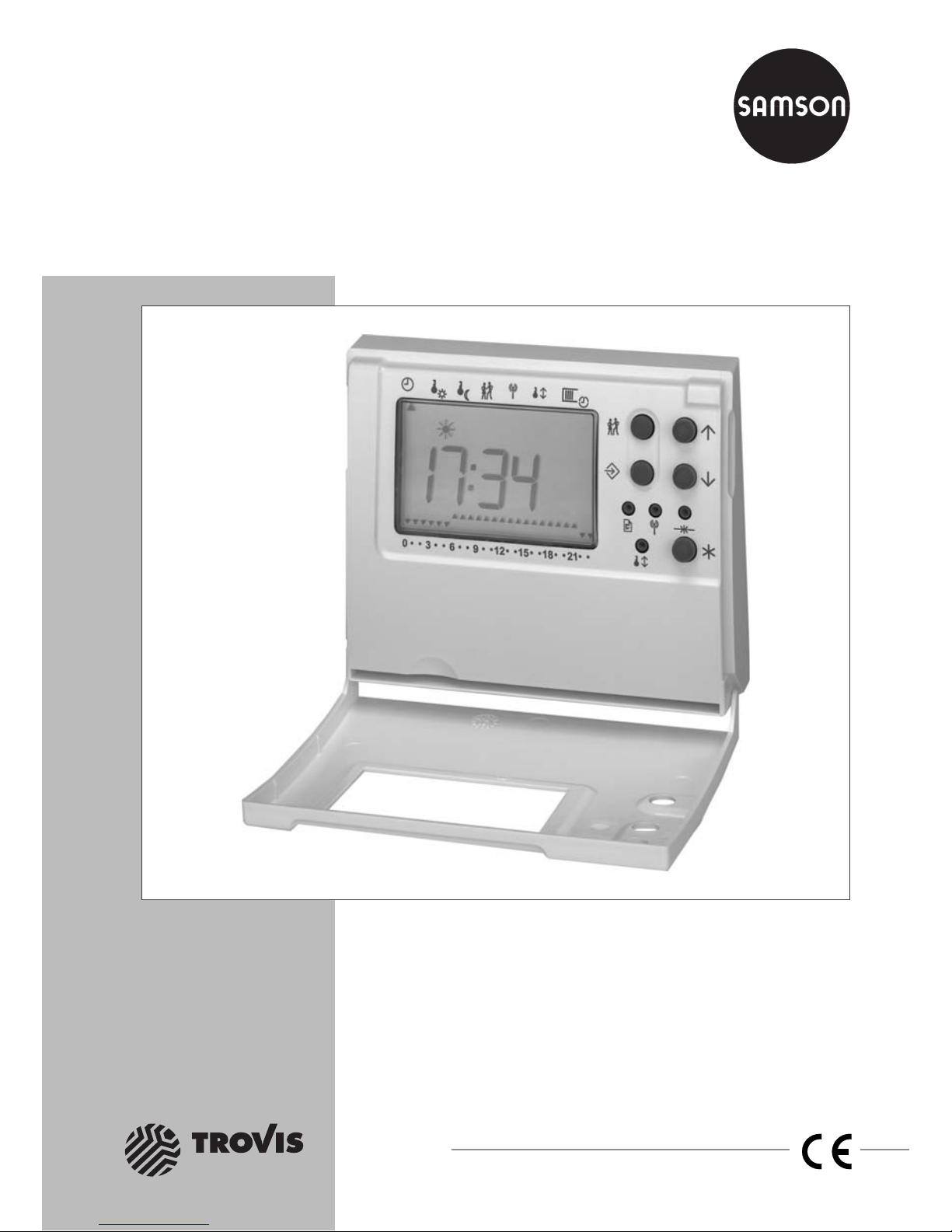
Automation System TROVIS 5500
Room Panel
TROVIS 5570
Mounting and
Operating Instructions
EB 5570 EN
®
Electronics from SAMSON
Firmware version 1.0x
Edition March 2003
Page 2

Disclaimer of liability
We are constantly developing our products and therefore reserve the right to change the
product or the information contained in this document at any time without notice.
We do not assume any liability for the accuracy or completeness of these mounting and
operating instructions. Moreover, we do not guarantee that the buyer can use the product
for an intended purpose. SAMSON rejects any liability for claims by the buyer, especially
claims for compensation including lost profits or any other financial loss, except the damage
was caused by wrongful intent or by gross negligence. If an essential term of the contract is
breached by negligence, SAMSON’s liability is limited to the foreseeable damage.
Safety instructions
4
The device may only be assembled, started up and operated by trained,
experienced personnel familiar with the product. Proper shipping and
appropriate storage are assumed.
4
Safety functions such as excess temperature protection or frost protection are
not available if power has failed, “manual operation” has been selected on
the heating and district heating controller or if any fault has occurred.
2 EB 5570 EN
Disclaimer of liability
Page 3

Contents
1 Operation . . . . . . . . . . . . . . . . . . . . . . . . . . . . . . . 4
1.1 Operating elements. . . . . . . . . . . . . . . . . . . . . . . . . . . 4
1.2 Displaying data . . . . . . . . . . . . . . . . . . . . . . . . . . . . 5
1.3 Selecting the operating mode . . . . . . . . . . . . . . . . . . . . . . 6
1.4 Setting the data . . . . . . . . . . . . . . . . . . . . . . . . . . . . 7
1.4.1 Setting the clock . . . . . . . . . . . . . . . . . . . . . . . . . . . . 7
1.4.2 Setting the times of use . . . . . . . . . . . . . . . . . . . . . . . . . 8
1.4.3 Setting the temperature set points . . . . . . . . . . . . . . . . . . . . 9
1.4.4 Setting the party mode . . . . . . . . . . . . . . . . . . . . . . . . . 9
2 Start-up. . . . . . . . . . . . . . . . . . . . . . . . . . . . . . . . 10
2.1 Calibrating the room sensor . . . . . . . . . . . . . . . . . . . . . . 11
3 Installation . . . . . . . . . . . . . . . . . . . . . . . . . . . . . . 11
4 Electrical connection. . . . . . . . . . . . . . . . . . . . . . . . . . 12
5 Technical data . . . . . . . . . . . . . . . . . . . . . . . . . . . . 12
EB 5570 EN 3
Contents
Page 4

1 Operation
The room panel, a remote room controller, will be ready for use after it has been connected
and started up. If the phone icon located in the top left-hand corner flashes, repeat the
start-up procedure (–> p. 10).
1.1 Operating elements
Arrow keys (up and down keys)
Are used to select data and parameters.
Manual key
Is used to switch between the operating modes.
Additional operating elements accessible with the cover open
Enter key
Is used to confirm a selection or setting.
Switch-over key
Is used to switch between the operating and parameter levels.
Party key
Is used to adjust the party timer (to prolong or start rated operation).
Note that you require a slim object such as a ball-point pen in order to press the following
keys:
Telegram key
Is used to register the room panel with the associated heating and district heating
controller (start-up).
Communication key
Is used to determine the device bus address (start-up).
Reset key
Is used to reset the room panel to default values (delivery state).
Pressing the reset key requires the room panel to be started up again.
Correction key
Is used to calibrate the room sensor (–> section 2.1).
4 EB 5570 EN
Operation
Page 5
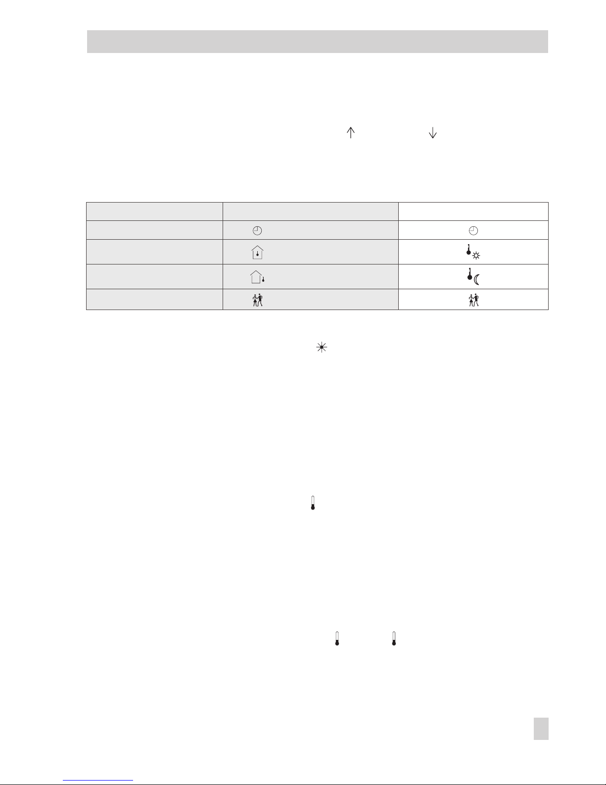
1.2 Displaying data
The data are displayed in turn on each press of the key. Use the key to display the
data in reverse order. The arrow (data indicator) at the top of the display indicates the data
selected, by pointing to the corresponding icon printed on the housing of the room panel. It
is recommended that the desired data be selected with the cover closed to ensure that the
data displayed are assigned to the appropriate icons.
Data Icons with the cover closed Icons with the cover open
Data 1 = Clock
Data 2
= Room temperature
Data 3
= Outdoor temperature
Data 4
= Party mode
Data 1: Clock _ _:_ _
Operating mode When is displayed = rated operation
When no symbol is displayed = reduced operation
Times of use 5 Time of use
6 Time of non-use
Data 2: Room temperature _ _._
Day/night set point
_ _._ (displayed in a smaller font in the bottom
right-hand corner)
Data 3: Outdoor temperature _ _._
Data 4: Party timer _ _:_ _
In addition to these four data, up to ten further process data received from the connected heat
ing and district heating controller (i.e. a maximum of five measured temperature values and
five dimensionless values) can be displayed provided that the appropriate setting of the control
-
ler has been selected previously.
Measured temperature values 1 to 5: _ _._ to _ _._
Dimensionless values 1 to 5: _ _._ to _ _._
EB 5570 EN 5
Operation
1 5
15
Page 6

Important!
If the phone icon flashes in the top left-hand corner, the connection to the heating and
district heating controller is faulty.
1.3 Selecting the operating mode
Press the key repeatedly to cycle through the following operating modes:
Rated operation (day): and ; 55555…
The day set point (rated operation) will be continuously maintained regardless of the
programmed times of use.
Reduced operation (night): ; 66666…
The night set point (reduced operation) will be continuously maintained regardless of
the programmed times of use.
Standby operation: and ; 66666…
Control will be switched off.
Automatic operation: will be displayed during times of use, no symbol will be displayed during times of non-use; 6…5…6
Rated operation will be activated during the programmed times of use, and reduced operation will be activated outside the times of use provided that the control operation has
not been switched off depending on the outdoor temperature. The controller will automatically switch between the two operating modes.
Note!
The operating mode selected on the room panel will only be adopted by the heating and dis
-
trict heating controller if the heating and district heating controller is set to “automatic opera
tion.” Otherwise, after a few seconds, the room panel will again display the operating mode
as set in the heating and district heating controller.
6 EB 5570 EN
Operation
Page 7

1.4 Setting the data
The room panel allows for direct setting of the clock, times of use, day set point, night set
point and party mode in the parameter level.
Note!
If the user fails to press a key for two minutes, the room panel will leave the parameter level.
1.4.1 Setting the clock
Proceed as follows:
Open the cover.
Press this key to enter the parameter level.
The arrow (data indicator) at the top of the display will point to .
The display will show the time.
Press this key to enter the editing mode.
Edit the time.
Confirm the time.
The display will show the year.
Edit the year.
Confirm the year.
The display will show the date.
Edit the date.
Confirm the date.
The display will show the day set point.
Leave the parameter level.
EB 5570 EN 7
Operation
Page 8

1.4.2 Setting the times of use
Three times of use can be programmed for each day of the week. If one time of use is not
required, be sure that the start and stop times are adjusted to identical values.
Proceed as follows:
Open the cover.
Press this key to enter the parameter level.
The arrow (data indicator) at the top of the display will point to .
The display will show the time.
Press this key using single key presses until the arrow at the top of the display will point
to and the display will show 1−7 (= daily). Further pressing of this key will toggle
through the days of the week: 1 = Monday, 2 = Tuesday, ..., 7 = Sunday.
Press this key to enter the editing mode.
The start time of the first time of use will be displayed.
Edit the start time (in 15-minute increments).
Confirm the start time.
The stop time of the first time of use will be displayed.
will flash.
Edit the stop time.
Confirm the stop time.
The start time of the second time of use will be displayed.
Repeat the instructions highlighted in gray to set the second and third times of use.
After having set all times of use:
Leave the parameter level.
8 EB 5570 EN
Operation
Page 9

1.4.3 Setting the temperature set points
The day set point specifies the room temperature to be maintained during rated operation.
The night set point specifies the room temperature to be maintained during reduced opera
-
tion. When adjusting the set points in the parameter level, the following applies:
Parameter Arrow points to Display
Day set point _ _._, ,
Night set point _ _._,
Proceed as follows:
Open the cover.
Press this key to enter the parameter level.
The arrow (data indicator) at the top of the display will point to .
The display will show the time.
Select the desired temperature set point.
Press this key to enter the editing mode.
Edit the temperature set point.
Confirm the temperature set point.
Leave the parameter level.
1.4.4 Setting the party mode
You can use the party mode to extend the current time of use for rated operation or to start
rated operation when the controller is still in reduced operation, by specifying the desired
party time for the party mode. When the programmed party time has elapsed, the display
of the party mode will be reset to 00:00.
Open the cover.
Press this key to enter the editing mode.
Edit the desired duration of the one-off time of use (minutes will change in 15-minute
increments).
Confirm the duration of the one-off time of use.
Leave the parameter level.
EB 5570 EN 9
Operation
Page 10

2 Start-up
The TROVIS 5570 Room Panel is intended to be used in combination with a heating and dis
-
trict heating controller from the TROVIS 5500 Series.
The start-up of the room panel requires the heating and district heating controller to be con
figured as specified below. Refer to the respective mounting and operating instructions for
detailed information on how to configure the TROVIS 5575 Controller (EB 5575 EN), TROVIS
5576 Controller (EB 5576 EN) or TROVIS 5579 Controller (EB 5579 EN).
Configuration of the heating and district heating controller from the TROVIS 5500 Series
Functions
Default Configuration
Device bus 0
32
CO7 -> F01 - 1
Device bus address / Auto*, 1…32
TROVIS 5570 Room Panel in Rk1
(Rk2, Rk3)
0 CO7 -> F03 - 1
(CO7 -> F04 - 1, CO7 -> F05 - 1)
Choice: Auto**
* Auto = automatically searches for a free device bus address in the system
** Auto = automatically searches for a room panel in enabled identifying mode
Proceed as follows:
For the heating and district heating controller: adjust the above-mentioned configuration.
For the room panel:
Initiate start-up.
The room panel will display: 6 – 32.
Adjust the device bus address.
E.g. 6 – 02 for device bus address 2.
Confirm the device bus address.
The display will flash the time.
Press this key to transmit the identifying code to the heating and district heating control
ler and to establish communication between the room panel and the heating and district
heating controller. The room panel will directly receive and adopt the time and further
information from the heating and district heating controller.
Important!
If the phone icon flashes in the upper left-hand corner, start-up has not been carried out
properly and must be repeated.
10 EB 5570 EN
Start-up
Page 11

2.1 Calibrating the room sensor
If the temperature displayed by the room panel does not correspond with the actual room
temperature, the value measured by the room sensor can be changed and readjusted. When
calibrating the room sensor, change the currently displayed sensor value to the reference
value, i.e. the directly measured room temperature.
Note!
If calibration has not been carried out properly, incorrect room temperature values will be
measured, leading to a poor control behavior. A high-precision thermometer will be re
-
quired to determine the reference value.
Proceed as follows:
Press the correction key.
Adjust the determined temperature difference.
Confirm the temperature difference.
3 Installation
Note!
Install the room panel 1.50 m above the floor.
In order to ensure proper operation of the room panel, do not locate it in a place where it
could be exposed to heat sources, such as close to radiators, lights and electrical devices, or
in a place where it could be exposed to draughts, such as close to doors or windows.
The room panel must not be covered by curtains or furniture.
EB 5570 EN 11
Installation
Page 12

4 Electrical connection
Prior to connecting the room panel to the heating and district heating controller, route two
wires (or four wires including two wires for the power supply) in the building.
When connecting the devices, there is no particular polarity requirement.
Connecting to the TROVIS 5575 Heating and District Heating Controller:
Connect terminals 5 and 6 of the room panel to terminals 14 and 15 of the controller device
bus. The power supply of the room panel (terminals 1 and 2 of the room panel (12 to
26.5 V AC/15 to 36 V DC)) is to be provided by the customer.
Connecting to the TROVIS 5576 or TROVIS 5579 Heating and District Heating Controller:
Refer to Fig. 1.
5 Technical data
12 EB 5570 EN
Electrical connection
Interface
Device bus RS-485 interface for connection to controllers from the TROVIS 5500
Series (two-wire, polarity-insensitive connection)
Operating voltage 15 to 36 V DC (polarity insensitive)
12 to 26.5 V AC, 48 to 62 Hz
Ambient conditions 0 to 50 °C (operation)
–10 to 60 °C (storage and transport)
95 % rF, non-condensing
Degree of contamination 2 according to VDE 0110
Noise immunity According to EN 61000-6-1
Noise emission According to EN 61000-6-3
Dimensions in mm
Width x height x depth 113 x 91 x 30
Page 13

EB 5570 EN 13
12...26.5V AC/
15...36V DC
BA12
BA13
UP1 On/off
UP1 Speed
Pump management - COM
COM BA12, BA13
Y COM
TROVIS 5576TROVIS 5570
Y1
Y2
0...10V
0...10V
23
22
21
20
19
24
25
26
27
28
29
30
1
2
3
4
5
6
7
8
9
Fig. 1 · Connecting the TROVIS 5570 Room Panel to the TROVIS 5576 or TROVIS 5579 Heating and District Heating Controller
Note!
The controller can only supply the room panel with
power if no meter bus plug-in module is installed.
Page 14

Page 15

Page 16

SAMSON AG ⋅ MESS- UND REGELTECHNIK
Weismüllerstraße 3 ⋅ 60314 Frankfurt am Main ⋅ Germany
Phone: +49 69 4009-0 ⋅ Fax: +49 69 4009-1507
Internet: http://www.samson.de
EB 5570 EN
2003-03
 Loading...