

Page 1
Automation System TROVIS 5400
Ventilation Controller
TROVIS 5477
Electronics from SAMSON
Mounting and
Operating Instructions
EB 5477 EN
®
Firmware version 2.0x
Edition April 2004
Page 2
Disclaimer of liability
Disclaimer of liability
We are constantly developing our products and therefore, reserve the right to change the
product or the information in this document at any time without notice.
We do not assume any liability for the accuracy or completeness of these mounting and op
erating instructions. SAMSON rejects liability for claims by the buyer, especially claims for
compensation including lost profits or any other financial loss, except the damage was
caused intentionally or by gross negligence. If an essential term of the contract is breached
by negligence, SAMSON's liability is limited to the foreseeable damage.
Safety instructions
Assembly, start-up and operation of this device may only be performed by
4
trained and experienced personnel familiar with this product. Proper transportation and storage are assumed.
The controller is intended for use in electrical power installations. For wiring
4
and maintenance, you are required to observe the relevant safety regulations.
-
What’s new compared to previous version (1.9)
Compared to the firmware version 1.9, the following changes have been made:
A two-second delay before a sensor failure is detected and before a binary input state
4
changes to suppress error messages caused by signal distortion.
The system bus interface can be switched over from 8-bit addressing to 16-bit addressing
4
(Fb44).
When the modem is in operation, if you keep the enter key pressed when the time ap
4
pears on the display, the current connection status “Free”, “Call”, “Conn” or “Ring” is
shown.
2 EB 5477 EN
-
Page 3

Contents
Table of contents
1 Operation . . . . . . . . . . . . . . . . . . . . . . . . . . . . . . . 6
1.1 Operating controls . . . . . . . . . . . . . . . . . . . . . . . . . . . 6
1.1.1 Operating keys . . . . . . . . . . . . . . . . . . . . . . . . . . . . . 6
1.1.2 Mode switches . . . . . . . . . . . . . . . . . . . . . . . . . . . . . 7
1.2 Operating modes. . . . . . . . . . . . . . . . . . . . . . . . . . . . 8
1.3 Display. . . . . . . . . . . . . . . . . . . . . . . . . . . . . . . . . 9
1.4 Data retrieval . . . . . . . . . . . . . . . . . . . . . . . . . . . . . 10
1.5 Setting the time and date . . . . . . . . . . . . . . . . . . . . . . . 10
1.6 Programming the time schedule . . . . . . . . . . . . . . . . . . . . 12
1.6.1 Entering public holidays . . . . . . . . . . . . . . . . . . . . . . . . 14
1.6.2 Entering vacations. . . . . . . . . . . . . . . . . . . . . . . . . . . 15
2 Start-up. . . . . . . . . . . . . . . . . . . . . . . . . . . . . . . . 17
2.1 Setting the system code number and control method . . . . . . . . . . 17
2.2 Activating and deactivating functions. . . . . . . . . . . . . . . . . . 19
2.3 Changing parameters . . . . . . . . . . . . . . . . . . . . . . . . . 20
2.4 Calibrating sensors . . . . . . . . . . . . . . . . . . . . . . . . . . 21
2.5 Entering the key number . . . . . . . . . . . . . . . . . . . . . . . . 22
2.6 Resetting default setting . . . . . . . . . . . . . . . . . . . . . . . . 22
3 Manual operation. . . . . . . . . . . . . . . . . . . . . . . . . . . 23
4 Systems. . . . . . . . . . . . . . . . . . . . . . . . . . . . . . . . 24
4.1 System code number 9 . . . . . . . . . . . . . . . . . . . . . . . . 36
5 Control methods and system components . . . . . . . . . . . . . . . 37
5.1 Ventilation and temperature control in air-conditioning systems . . . . . 37
5.1.1 Supply air temperature control . . . . . . . . . . . . . . . . . . . . . 37
5.1.2 Exhaust air temperature control . . . . . . . . . . . . . . . . . . . . 37
5.1.3 Exhaust air temperature cascade control . . . . . . . . . . . . . . . . 38
5.1.4 Room temperature control . . . . . . . . . . . . . . . . . . . . . . . 39
5.1.5 Room temperature cascade control. . . . . . . . . . . . . . . . . . . 40
5.2 Humidity control in air-conditioning systems (Anl 6, 8 and 9) . . . . . . 41
5.2.1 Supply air humidity control . . . . . . . . . . . . . . . . . . . . . . 41
5.2.2 Exhaust air/room humidity control . . . . . . . . . . . . . . . . . . . 42
5.2.3 Exhaust air or room humidity cascade control
5.3 Inputs. . . . . . . . . . . . . . . . . . . . . . . . . . . . . . . . . 44
5.4 Outputs . . . . . . . . . . . . . . . . . . . . . . . . . . . . . . . . 44
5.4.1 Heating coil. . . . . . . . . . . . . . . . . . . . . . . . . . . . . . 44
5.4.2 Mixed air chamber . . . . . . . . . . . . . . . . . . . . . . . . . . 45
5.4.3 Heat recovery unit (HRU) . . . . . . . . . . . . . . . . . . . . . . . 48
. . . . . . . . . . . . . 42
EB 5477 EN 3
Page 4

Contents
5.4.4 Cooling coil. . . . . . . . . . . . . . . . . . . . . . . . . . . . . . 49
5.5 Humidifier . . . . . . . . . . . . . . . . . . . . . . . . . . . . . . 50
5.6 Fans with variable speed . . . . . . . . . . . . . . . . . . . . . . . 51
6 Control functions . . . . . . . . . . . . . . . . . . . . . . . . . . . 53
6.1 Supply air temperature limit . . . . . . . . . . . . . . . . . . . . . . 53
6.2 Supply air humidity limit . . . . . . . . . . . . . . . . . . . . . . . 53
6.3 Return air temperature limit . . . . . . . . . . . . . . . . . . . . . . 54
6.4 Variable return air temperature maximum limit . . . . . . . . . . . . . 54
6.5 Sustained room temperature . . . . . . . . . . . . . . . . . . . . . . 55
6.6 Night purge. . . . . . . . . . . . . . . . . . . . . . . . . . . . . . 56
6.7 Summer compensation. . . . . . . . . . . . . . . . . . . . . . . . . 57
6.8 Fan operation dependent on room temperature/room humidity . . . . . 57
6.9 Air quality control via the mixed air chamber . . . . . . . . . . . . . 58
6.10 Outdoor temperature-compensated control . . . . . . . . . . . . . . . 59
6.10.1 Outdoor temperature-compensated supply air control . . . . . . . . . . 59
6.10.2 Summer deactivation . . . . . . . . . . . . . . . . . . . . . . . . . 60
6.10.3 Summer time operation
6.11 Control functions . . . . . . . . . . . . . . . . . . . . . . . . . . . 61
6.11.1 System start-up . . . . . . . . . . . . . . . . . . . . . . . . . . . . 61
6.11.2 Circulating air mode after system start-up . . . . . . . . . . . . . . . 62
6.11.3 Enabling fan speed 1 . . . . . . . . . . . . . . . . . . . . . . . . . 62
6.11.4 Enabling fan speed 2 . . . . . . . . . . . . . . . . . . . . . . . . . 63
6.11.5 Fan operation feedback . . . . . . . . . . . . . . . . . . . . . . . . 64
6.11.6 Enabling the cold storage . . . . . . . . . . . . . . . . . . . . . . . 64
6.11.7 Controlling the direct expansion evaporator . . . . . . . . . . . . . . 65
6.11.8 Controlling the chiller . . . . . . . . . . . . . . . . . . . . . . . . . 65
6.11.9 Condensation detection . . . . . . . . . . . . . . . . . . . . . . . . 66
6.11.10 Circulation pump control for the heating coil . . . . . . . . . . . . . . 66
6.11.11 Circulation pump control for the HRU. . . . . . . . . . . . . . . . . . 67
6.11.12 Electric air heater . . . . . . . . . . . . . . . . . . . . . . . . . . . 67
7 System-wide functions . . . . . . . . . . . . . . . . . . . . . . . . 68
7.1 Switchover between summer time and winter time . . . . . . . . . . . 68
7.2 Frost protection . . . . . . . . . . . . . . . . . . . . . . . . . . . . 68
7.2.1 System frost protection. . . . . . . . . . . . . . . . . . . . . . . . . 68
7.2.2 Frost protection HRU. . . . . . . . . . . . . . . . . . . . . . . . . . 68
7.2.3 Stand-by monitoring. . . . . . . . . . . . . . . . . . . . . . . . . . 69
7.2.4 Stand-by control . . . . . . . . . . . . . . . . . . . . . . . . . . . 69
7.3 Forced-operation of the pumps . . . . . . . . . . . . . . . . . . . . 69
7.4 External correction of the temperature set point . . . . . . . . . . . . . 70
. . . . . . . . . . . . . . . . . . . . . . . . 60
4 EB 5477 EN
Page 5

Contents
7.5 External setting of the outdoor air rate . . . . . . . . . . . . . . . . . 70
7.6 External correction of the humidity set point . . . . . . . . . . . . . . 70
7.7 External setting of the air volume . . . . . . . . . . . . . . . . . . . 71
7.8 External demand for operation . . . . . . . . . . . . . . . . . . . . 71
7.9 External demand for fan speed 2. . . . . . . . . . . . . . . . . . . . 72
7.10 External selection of the operating mode . . . . . . . . . . . . . . . . 73
7.10.1 External selection of the operating mode using the four-staged switch . . 73
7.10.2 External selection of the operating mode using Type 5257-6 Room Panel 73
7.11 Request for externally required signal . . . . . . . . . . . . . . . . . 75
7.12 Outdoor temperature output . . . . . . . . . . . . . . . . . . . . . . 76
7.13 Locking settings . . . . . . . . . . . . . . . . . . . . . . . . . . . . 76
8 Malfunctions . . . . . . . . . . . . . . . . . . . . . . . . . . . . . 77
8.1 Sensor failure . . . . . . . . . . . . . . . . . . . . . . . . . . . . . 77
8.1.1 Status register (FSR) . . . . . . . . . . . . . . . . . . . . . . . . . . 77
9 Communication . . . . . . . . . . . . . . . . . . . . . . . . . . . . 79
9.1 RS-232-C serial interface . . . . . . . . . . . . . . . . . . . . . . . 80
9.2 RS-485 interface . . . . . . . . . . . . . . . . . . . . . . . . . . . 81
9.3 Description of the communication parameters to be set . . . . . . . . . 82
9.4 Memory module. . . . . . . . . . . . . . . . . . . . . . . . . . . . 83
10 Installation . . . . . . . . . . . . . . . . . . . . . . . . . . . . . . 84
11 Electrical connection. . . . . . . . . . . . . . . . . . . . . . . . . . 86
12 Appendix. . . . . . . . . . . . . . . . . . . . . . . . . . . . . . . 89
12.1 Function block list CO . . . . . . . . . . . . . . . . . . . . . . . . . 89
12.2 List of parameters . . . . . . . . . . . . . . . . . . . . . . . . . . . 96
12.3 Display . . . . . . . . . . . . . . . . . . . . . . . . . . . . . . . 107
12.4 Technical data . . . . . . . . . . . . . . . . . . . . . . . . . . . . 109
12.5 Resistance values. . . . . . . . . . . . . . . . . . . . . . . . . . . 110
12.6 Customer data . . . . . . . . . . . . . . . . . . . . . . . . . . . . 111
EB 5477 EN 5
Page 6
Operation
1 Operation
1.1 Operating controls
The TROVIS 5477 Ventilation Controller can be operated using the operating controls on the
front panel.
The controller is ready for operation using its default temperature and time schedule settings.
On start-up, after switching on the power supply, the correct time and date must be set in
the controller (–> section 1.5).
1.1.1 Operating keys
The operating keys are located on the front of the controller and protected by a transparent
cover.
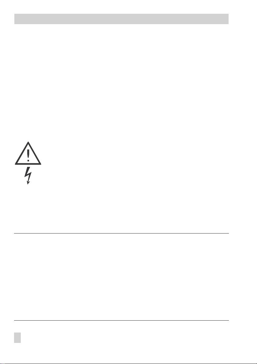
Changeover key
(press with pencil or similar pointed object)
Allows you to change between the operating level, parameter level and
configuration level.
Reset key
(press with pencil or similar pointed object)
Allows you to reset all freely accessible parameters to default values (factory
setting). This key’s function is only active on the parameter level
6 EB 5477 EN
Arrow keys
Allow you to retrieve and set parameters
Enter key
Operating level: allows you to read set points
Parameter level: allows you to access and acknowledge parameters
Configuration level: allows you to access and acknowledge function
blocks
Page 7
Operation
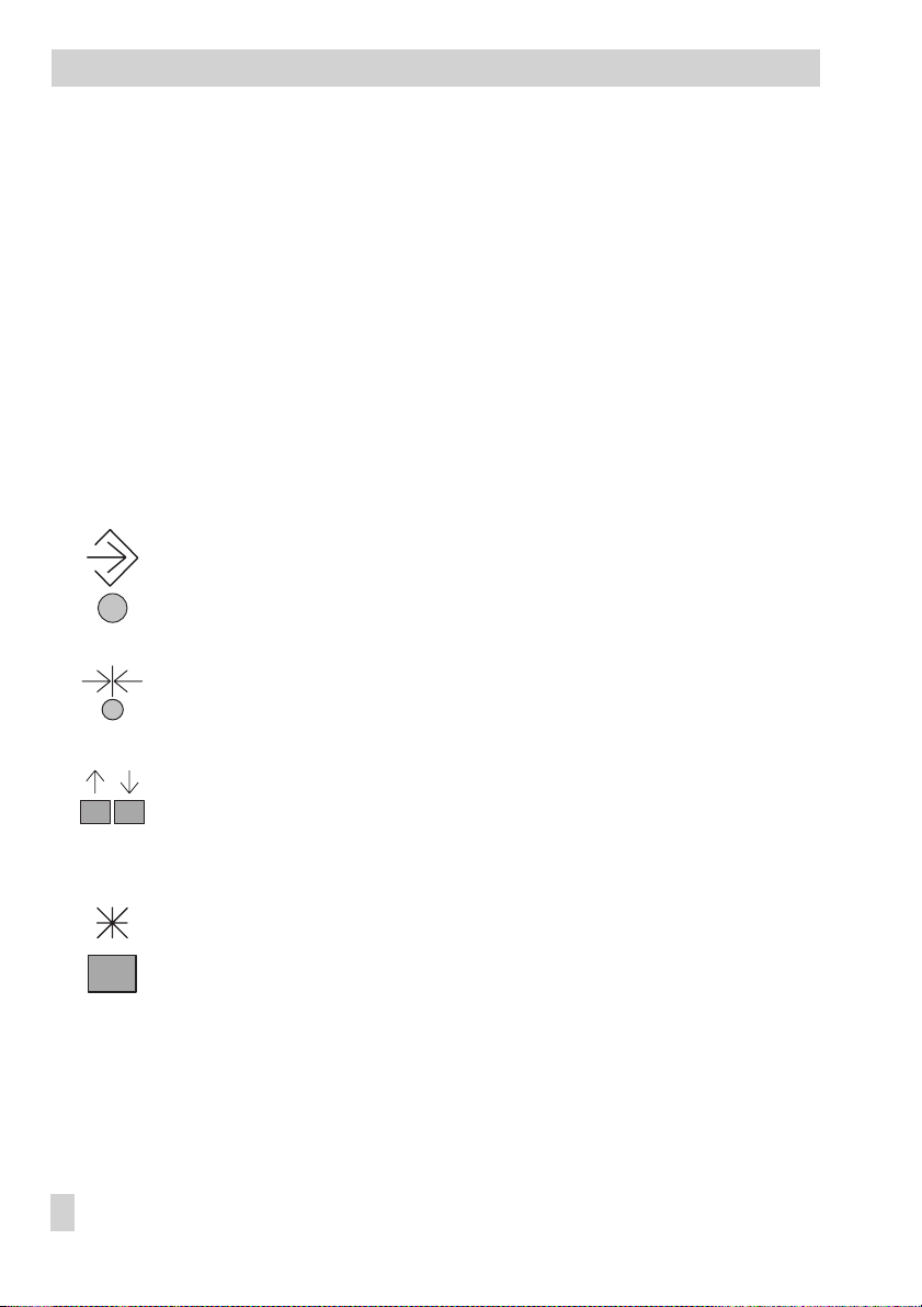
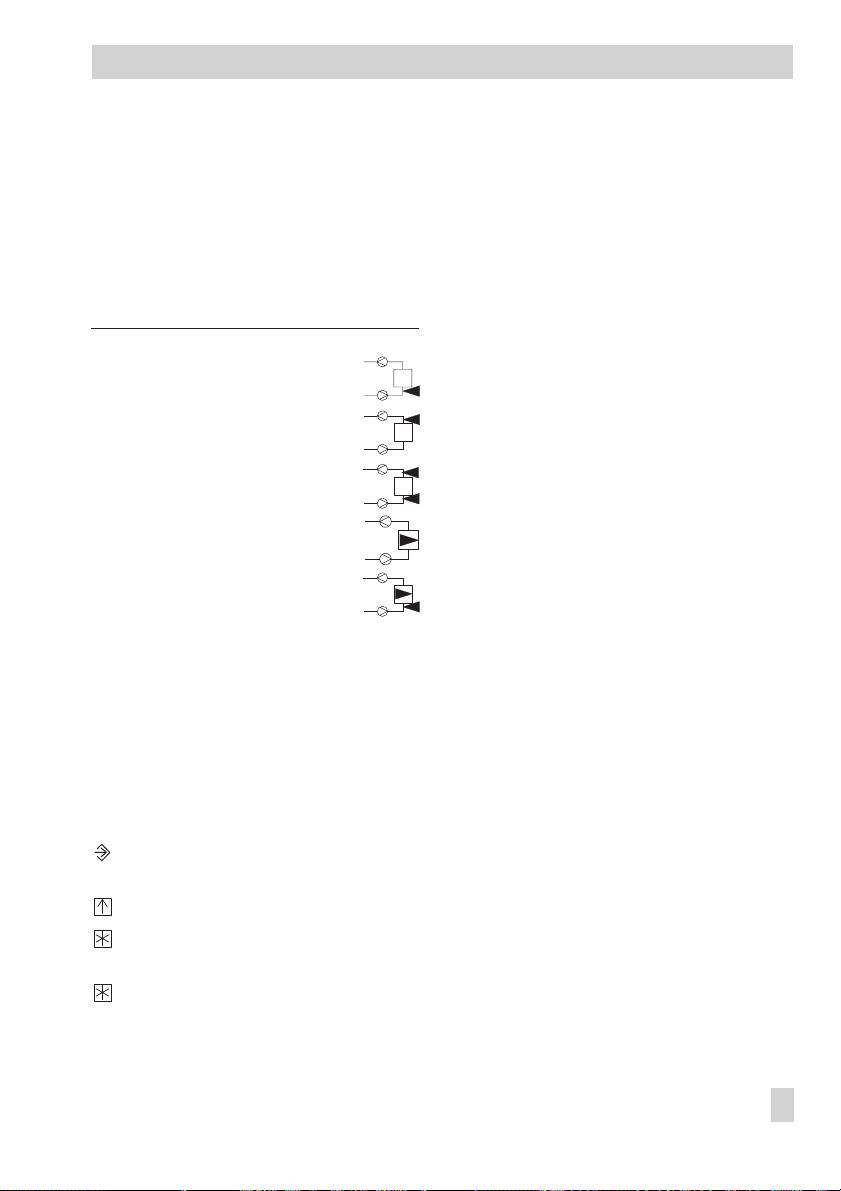
1.1.2 Mode switches
Operating mode switch
Automatic operation with switchover between rated and re
duced operation
Rated operation
Reduced operation
Manual operation
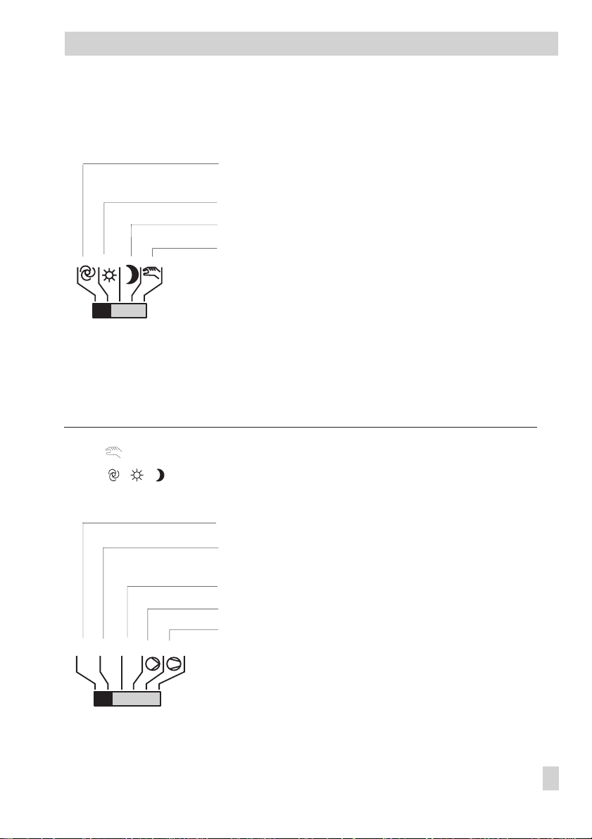
Selection switch for manual operation
The function of the selection switch depends on the position of the operating mode switch
(see above).
Position Function
at operating mode switch at selection switch for manual operation
-
Operation of selected output
,, Display of output states
Control output Y1 (heating coil)
Control output Y2 (humidifier, mixed air chamber, heat
recovery unit)
Control output Y3 (cooling coil)
Pump(s)
Fans
Y
Y
Y
2
1
3
EB 5477 EN 7
Page 8
Operation
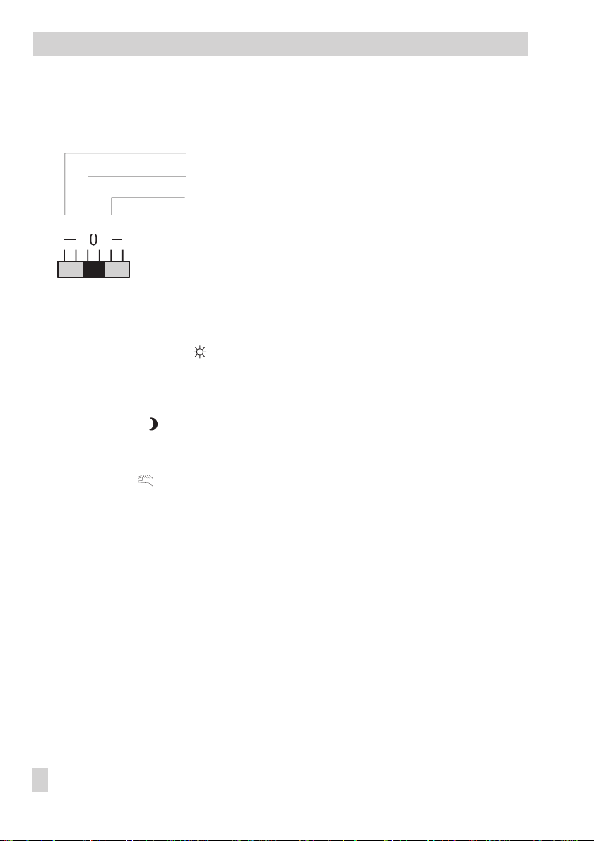
Set point correction switch
Changes remain effective until the switch position is changed again
–: Set point reduction in 1 °C increments per notch
0: No change in set point
+: Set point increase in 1 °C increments per notch
1.2 Operating modes
Day mode (rated operation) ( )
The set points set for rated operation are constantly used by the controller irrelevant of the
programmed time-of-use or summer mode.
Stand-by operation ( )
The ventilation is deactivated. The frost protection is active.
Manual operation ( )
Manual operation of valves and pumps.
8 EB 5477 EN
Page 9
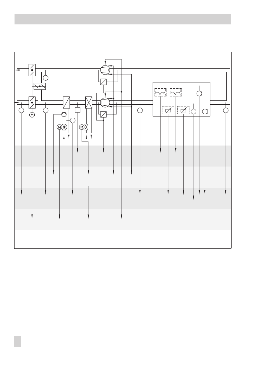
1.3 Display
Operation
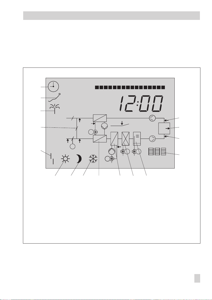
During operation, the display indicates the current time as well as information about the op
eration of the controller. The times-of-use are represented by black squares below the row of
numbers at the top of the display. Symbols indicate the operating status of the controller.
24
Y1 Y2 Y3
2322212019181716151413121110987654210
16
15
14
13
1
2
3
4
32˚C
5
6
7
1 Time schedule
2 Public holidays
3 Vacation
4 Mixed air chamber
5 Malfunction
6 Rated operation
7 Reduced operation
8 Frost protection
3
M
Y2
M
Y2
M
Y1
8
9
10
M
Y3MY2
11
12
9 Heat recovery unit
10 Heating coil
11 Cooling coil
12 Humidifier
13 Control outputs
14 Supply air temperature/humidity
15 Room temperature/humidity
16 Exhaust air temperature/humidity
-
Fig. 1 · Display while the controller is operating (example)
See section 1.4 for more information about how to read the current status of the controller in
the operating level.
EB 5477 EN 9
Page 10
Operation
1.4 Data retrieval
You can view information in the operating level concerning various temperatures, control
signals, times-of-use, public holidays, states of the binary inputs as well as the baud rate
(–> Fig. 30). Which temperatures are shown depends on the system code number and the
configuration.
You will find a list of the various displays in section .
How to proceed:
The controller shows the time.
Press the arrow key.
Every time you press the key, another dat point appears on the display.
If required, you can view other information concerning a data point.
1.5 Setting the time and date
Set the current date and time directly after start-up and after a power failure, if necessary.
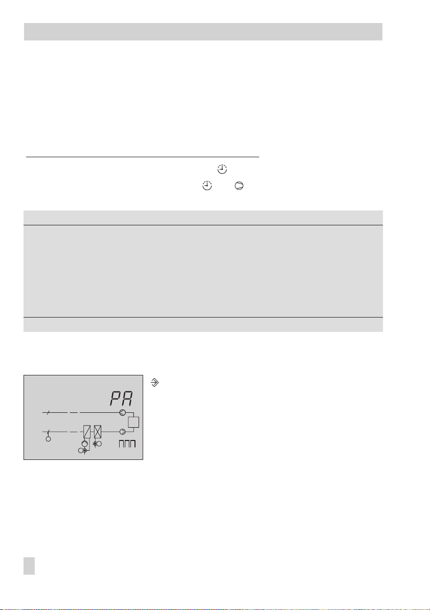
You must set the time and date in the parameter level.
How to proceed:
24
23222120191817161514131211109876542103
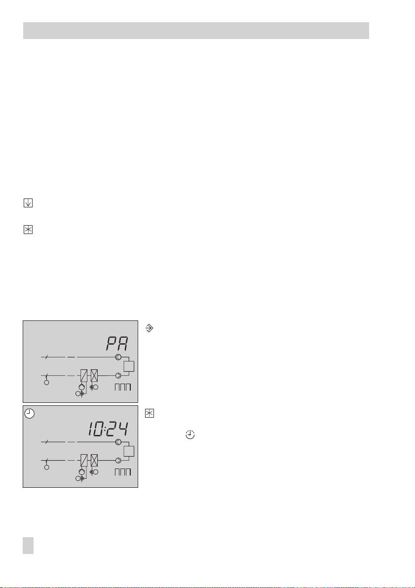
Switch to the configuration and parameter level.
PA
appears on the display.
CO
M
PA
M
10 EB 5477 EN
M
Y3
M
Y1
Y1 Y2 Y3
24
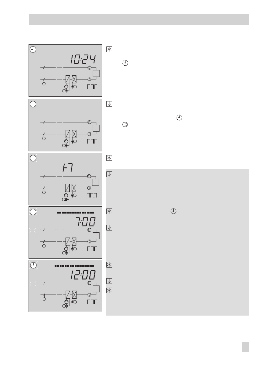
23222120191817161514131211109876542103
Press the enter key.
The time appears on the display.
The symbol starts to blink slowly.
M
Y3
M
Y1
Y1 Y2 Y3
Page 11
Operation
24
23222120191817161514131211109876542103
PA
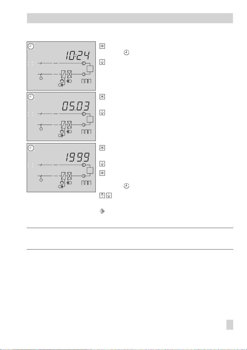
Press the enter key.
PA
The symbol and
blink quickly.
Use the arrow key to set the correct time.
M
M
Y3
M
Y1
Y1 Y2 Y3
24
23222120191817161514131211109876542103
Press the enter key to acknowledge the time.
A date appears on the display
PA
M
M
Y3
M
Y1
Y1 Y2 Y3
24
23222120191817161514131211109876542103
Use the arrow key to set the correct date.
Press the enter key to acknowledge the date.
The year appears on the display.
PA
Use the arrow key to set the correct year.
Press the enter key to acknowledge the year.
M
M
Y3
M
Y1
Y1 Y2 Y3
The time appears on the display again.
The symbol blinks slowly.
Press both arrow keys simultaneously.
PA
appears on the display again.
Press the changeover key to return to the operating
level.
Note:
The controller returns to the operating level two minute after the last key has been pressed.
EB 5477 EN 11
Page 12
Operation
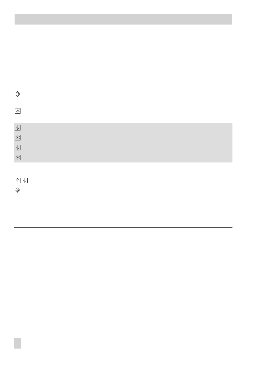
1.6 Programming the time schedule
You can enter two time periods for every day of the week.
If you need just one continuous time-of-use period, set the same time for the start of the sec
ond time period and the end of the first time period.
You can set separate times-of-use for the system and, if required, for the fan speed 2.
Times-of-use Display
System
Fan speed 2
START, STOP
START, STOP
and blink
, and blink
-
Parameters
WE* Range of values
Period/day 1–7 1–7, 1, 2, 3, 4, 5, 6, 7 with 1–7 = every day,
1–5 = Monday to Friday, 6–7= Saturday and Sunday,
1 = Monday, 2 = Tuesday, ..., 7 = Sunday
Start first time-of-use 7:00 0:00 to 24:00 h; in steps of 30 minutes
Stop first time-of-use 12:00 0:00 to 24:00 h; in steps of 30 minutes
Start second time-of-use 12:00 0:00 to 24:00 h; in steps of 30 minutes
Stop second time-of-use 22:00 0:00 to 24:00 h; in steps of 30 minutes
* Default setting (WE) valid for system
How to proceed:
24
23222120191817161514131211109876542103
CO
M
M
Y3
M
Y1
Y1 Y2 Y3
Switch to the configuration and parameter level.
PA
appears on the display.
12 EB 5477 EN
Page 13
Operation
24
23222120191817161514131211109876542103
Press the enter key to enter the parameter level.
The time appears on the display.
PA
blinks slowly.
M
STOP
START
PA
M
STOP
START
PA
M
Y3
M
Y1
Y1 Y2 Y3
24
23222120191817161514131211109876542103
Press the arrow key until the same display as shown
appears for changing the system times-of-use.
START, STOP
(
and the symbol start to blink,
additionally blinks with fan speed 2).
M
Y3
M
Y1
Y1 Y2 Y3
24
23222120191817161514131211109876542103
Press the enter key.
1–7
appears on the display.
Select the duration/day for the times-of-use.
1–7 = Monday to Sunday
M
START
PA
M
STOP
PA
M
Y3
M
Y1
M
Y1
Y1 Y2 Y3
24
23222120191817161514131211109876542103
M
Y3
Y1 Y2 Y3
24
23222120191817161514131211109876542103
1–5 = Monday to Friday
6–7 = Saturday and Sunday
1 = Monday, 2 = Tuesday, …, 7 = Sunday
Press enter key. The symbol andPAstart to blink
START
quickly.
and a time appear on the display.
Set the start time (30-minute steps).
Press the enter key.
STOP
and a time appear on the display.
Set the stop time (30-minute steps).
Press the arrow key
START
M
M
Y3
M
Y1
Y1 Y2 Y3
and a time appear on the display.
The second time-of-use period can set in the same
way as the first time-of-use period.
Repeat the steps in the gray box to enter times-of-use for other days not yet programmed.
EB 5477 EN 13
Page 14
Operation
Select
End
.
Exit the parameter level.
Return to the operating level.
Note! The controller automatically returns to the operating level when keys are left unpressed
for longer than two minutes.
Note! Use just the menu for the individual days to check the programmed time schedules. When
time blocks are selected, the times-of-use for the days selected are reset to default settings!
1.6.1 Entering public holidays
The controller uses the times-of-use programmed for Sundays on public holidays.
You can enter a maximum of 20 public holidays.
Parameter
Public holidays 01.01; 01.05;
How to proceed: Switch to the configuration and parameter level.
0123456789101112131415161718192021222324
PA
M
Y2
M
Y2
Y1
M
To enter other public holidays, press the arrow key until
again. Repeat the steps in the gray box.
WE Range of values
01.01 (1 Jan) to 31.12 (31 Dec)
25.12; 26.12
PA
appears on the display.
Press the enter key.
The time appears on the display, blinks slowly.
Select public holidays data point.
appears on the display.
Press the enter key to access data point.
Press the arrow key until
M M
Y3 Y2
Y1 Y2 Y3
sary.
Press the enter key.
The symbol blinks quickly.
Change the date of the public holiday.
Confirm the date of the public holiday.
– – – –
– – – –
appears, if neces
appears on the display
-
14 EB 5477 EN
Page 15
Operation
Select
End
.
Exit the parameter level.
Return to the operating level.
Note! Public holidays that are not assigned to a specific date should be deleted by the end of
the year so that they are not carried on into the following year.
Deleting a public holiday:
Use the arrow key to select the public holiday you want to delete.
Press the enter key.
Press the arrow key until
– – – –
appears.
– – – –
is between 31.12 and 01.01.
Press the enter key. The public holiday is deleted.
1.6.2 Entering vacations
During vacation periods, the controller constantly remains in stand-by mode.All safety functions are activated. A maximum of 10 vacation periods can be entered.
Parameter
Vacation period (START, STOP) – 01.01 to 31.12
WE Range of values
How to proceed: Switch to the configuration and parameter level.
PA
appears on the display.
Press the enter key.
The time appears on the display, blinks slowly.
0123456789101112131415161718192021222324
Select vacation data point.
appears on the display.
PA
M
Y2
M
Y2
M M
Y1
Y3 Y2
M
Y1 Y2 Y3
Press the enter key to access vacation data point.
START
appears on the display.
Press the arrow key until
– – – –
appears, if neces
sary.
EB 5477 EN 15
-
Page 16

Operation
Press the enter key.
The symbol blinks quickly.
Set when the vacation period should start.
Press the enter key to confirm the start of the vacation period.
STOP
appears on the display.
Set when the vacation period should end.
Press the enter key to confirm the end of the vacation period.
To enter other vacations, press the arrow key until
peat the steps in the gray box.
End
Select
Exit the parameter level.
Return to the operating level.
.
– – – –
appears on the display again. Re
Note!
Vacations that have been entered should be deleted by the end of the year so that they are
not carried on into the following year.
Deleting a vacation period:
-
Select the start of the vacation period to be deleted.
Press the enter key.
Press the arrow key until
– – – –
Press the enter key.
The vacation period has been deleted.
16 EB 5477 EN
is between 31.12 and 01.01.
– – – –
appears on the display.
Page 17
2 Start-up
2.1 Setting the system code number and control method
Start-up
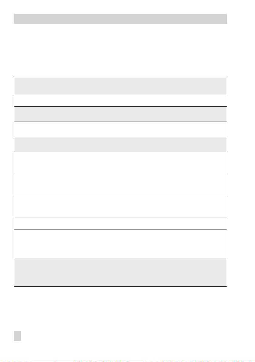
This ventilation controller allows ten different systems to be controlled. Each system is as
signed a system code number. You can find a list of the different systems in section 4. In ad
dition, the control method can be determined. The following control methods are available:
Control method Display
Supply air control
Exhaust air control
Exhaust air cascade control
Room control
Room cascade control
The control methods and functions of the controller are described in sections 5, 6 and 7.
Every change in system code number or control method causes the assignment of sensors to
be reprogrammed: the sensor inputs required for the function blocks are activated and the
sensor inputs not used are deactivated. These settings can be changed manually.
You must set the system code number in the configuration level (see Fig. 30).
How to proceed:
-
-
Change to the configuration and parameter level.
PA
appears on the display.
Select
CO
level.
Press the enter key.
The currently active system code number, e.g. Anl 1, blinks on the display.
Press the enter key.
Anl
andCOblink quickly.
EB 5477 EN 17
Page 18

Start-up
Select the required system code number.
Confirm the system you have selected.
Anl
starts to blink slowly on the display.
Press upward arrow key.
The components of the system and the arrows indicating the control method start to
blink on the display.
Press the enter key.
The components of the system and the control method arrows start to blink quickly on
the display.
Select the control method.
Confirm the control method you have selected.
System code numbers 6, 8 and 9:
Select the control method for the humidity control loop.
The humidity control loop is set in the same manner as the temperature control loop.
On selecting options, humidifying and dehumidifying mode or just humidifying mode
are differentiated between. In the humidifying mode, just the humidifier blinks.
CO
Press both arrow keys simultaneously.
Press the changeover key to return to the operating level.
appears on the display again.
Note!
The controller automatically returns to the operating level when keys are left unpressed for
longer than two minutes.
18 EB 5477 EN
Page 19

Start-up
2.2 Activating and deactivating functions
The controller is configured by setting the function blocks (Fb). You can activate or deactivate
CO
function blocks in the configuration level
square located to the right of a function block number at the top of the display indicates
whether function block is activated. The initial display shows the function blocks 1 to 24.
Scroll to the function blocks 25 to 47 to display the setting of these function blocks.
Proceed as described below to set the function block parameters.
How to proceed:
Change to the configuration and parameter level.
PA
appears on the display.
CO
Select
Enter the configuration level.
Select the required function block.
Confirm the function block you have selected.
If a function is protected,
(–> section 2.5) before a protected function block can be changed.
Press the upward arrow key to activate the function block (Fb = ON).
A black square to the right of the function block number at the top of the display indicates that the function block is activated.
or alternatively:
Press the downward arrow key to deactivate the function block (Fb = OFF).
Press the enter key to acknowledge the setting.
If the function block is left open, other parameters can be set. Proceed:
The parameter appears: Carry out change and confirm it.
Exit the function block.
Repeat the steps in the gray box to set other function blocks in the open configuration level.
Press both arrow keys simultaneously to exit parameter level.
Press the changeover key to return to the operating level.
configuration level.
0
Anl
appears on the display. The code number must be entered
. On opening the configuration level, a black
appears on the display.
Fb_
blinks.
Note! The controller automatically returns to the operating level when keys are left unpressed
for longer than two minutes.
EB 5477 EN 19
Page 20
Start-up
2.3 Changing parameters
Depending on the system code number set and the active functions, not all the parameters
are accessible which are listed in the parameter lists in the appendix (−> section 12.2).
How to proceed:
Change to the configuration and parameter level.
PA
appears on the display.
Press the enter key.
The time appears on the display.
Select the parameter you want to set.
Access the parameter.
Change the parameter.
Confirm the new parameter.
Repeat the steps in the gray box to set other parameters.
Press both arrow keys simultaneously to exit the parameter level.
Return to the operating level.
Note!
The controller automatically returns to the operating level when keys are left unpressed for
longer than two minutes.
20 EB 5477 EN
Page 21

Start-up
2.4 Calibrating sensors
The sensor calibration is performed in the configuration level.
Fb17 = ON: Pt 100 and Pt 1000 sensors
4
Fb17 = OFF: Pt 100 and PTC sensors
4
The values measured by all the connected sensors can be changed or reset. To proceed, set
the sensor value displayed to the temperature measured directly at the measuring point (ref
erence temperature).
Activate calibration with Fb1 to Fb7.
An incorrect calibration can be deleted by setting Fb1 to F7 = OFF.
How to proceed:
Change to the configuration and parameter level.
CO
Select
Enter the configuration level.
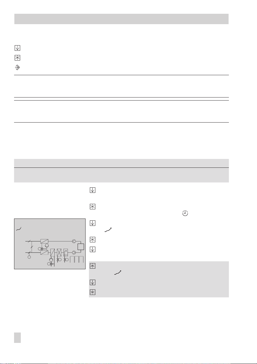
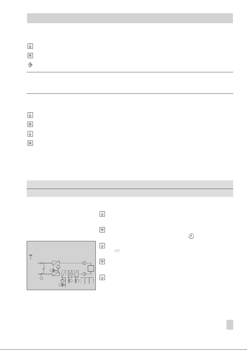
Press the upward arrow key until Fb25 appears on the display.
(This function block is merely selected to enter the code number. Another function
block that is protected by the code number can be also used.)
Press the enter key.
Enter and confirm the code number (–> section ) .
Close function block Fb 25.
Select the function block of the sensor that is to be calibrated (Fb1 to Fb7):
Fb1: Supply air sensor
Fb2: Exhaust air sensor
Fb3: Outdoor sensor
Fb4: Return flow sensor, heating coil
Fb5: Room sensor
Fb6: Return flow sensor, HR (system 3 and 5)
Fb7: Mixed air or extract air sensor (system 2 and 4)
Press the enter key.
A temperature appears on the display.
Set the temperature measured at the actual point of measurement.
The actual temperature at a thermometer direct at the point of measurement can be
used as the reference temperature.
configuration level.
0
appears on the display.
Anl
appears on the display.
Fb_
starts to blink.
-
EB 5477 EN 21
Page 22

Start-up
Confirm the new temperature.
End sensor calibration.
Other sensors can be calibrated in the same manner.
Press both arrow keys simultaneously to exit parameter level.
Return to the operating level.
2.5 Entering the key number
Several functions are protected against unintentional and unauthorized access. These func
tions can only be altered when the code number is known. The code number is written on
page 116. Tear out this page or blank out the code number to prevent its unauthorized use.
How to proceed:
0
appears on the display.
Press the arrow key until the correct code number appears on the display.
Confirm the code number.
When the correct code number is confirmed, the function block that should be
changed starts to blink quickly on the display.
The code number remains active for approx. three minutes.
2.6 Resetting default setting
Parameters from the parameter level can be reset to their default values (factory settings).
How to proceed:
Press the reset key with a pencil, etc.
All the parameters are reset to the factory setting (WE).
-
22 EB 5477 EN
Page 23

Manual operation
3 Manual operation
In manual operation mode, all outputs are set, see wiring plan (-> section 11 ).
How to proceed:
1. Set the operating mode switch to .
2. Slide the selector switch to the output you want to change:
Y1 to 3: control signal output 1 to 3
: pump(s) output
: fan(s) output
In systems with several pumps, select the pumps using the key.
The associated symbol blinks in the system diagram.
When the pumps are deactivated, just the pump circuit blinks on the display.
– – – – appears on the display when the output is not relevant for the system code num
ber selected.
3. Change the output:
Increase the control signal: activate pumps, fan
Reduce the control signal: deactivate pumps, fan .
For two-speed fans, you can select
The value does not need to be confirmed. It is kept even if you slide the selector switch to
another setting.
ON1,ON2orOFF
.
-
4. Slide the operating mode switch from to exit the manual operating mode.
Note!
In manual operation mode, the user can set the outputs anyway as required. On selecting
the manual operation mode, all limit temperatures and logical links ceased to be in force.
The user has absolute control and takes on responsibility for interaction between all the out
puts and the resulting consequences. A frost protection thermostat (Fb15 = ON) connected to
the controllers keeps functioning even in manual operation mode.
EB 5477 EN 23
Page 24
Systems
4 Systems
The ventilation controller can be used to control ten different types of systems which are as
signed system code numbers in the controller.
System code
number
0
1
2
3
4
5
6
7
8
9
* Also chilled ceiling or direct expansion evaporator (single-speed)
System description
Heating coil Ventilation
4
Heating coil
4
Cooling coil*
4
Heating coil
4
Mixed air chamber
4
Heating coil
4
Heat recovery unit
4
Heating coil
4
Cooling coil*
4
Mixed air chamber
4
Heating coil
4
Cooling coil*
4
Heat recovery unit
4
Heating coil
4
Cooling coil
4
Humidifier
4
Cooling coil* Ventilation
4
Heating coil
4
Cooling coil
4
Mixed air chamber
4
Humidifier
4
Heating coil
4
Cooling coil
4
Heat recovery unit
4
Humidifier
4
System type
Ventilation
Ventilation
Ventilation
Ventilation
Ventilation
Air-conditioning
Air-conditioning
Air-conditioning
-
24 EB 5477 EN
Page 25
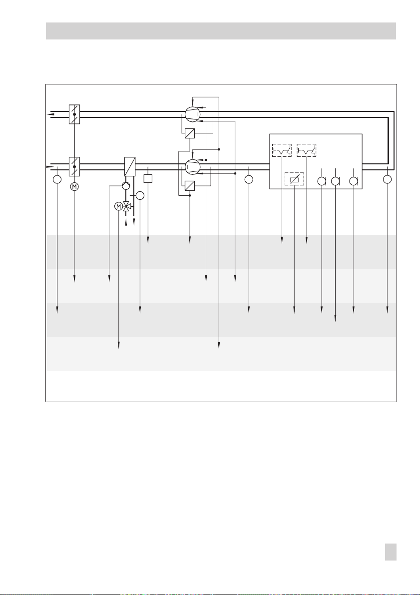
System code number 0
T
Systems
Ext. ON Ext. speed 2
Set point
T
T
T
rF
L
T
T
BE2
BA2 BA3
Speed 1 Speed 2
(AA)
BE1
F1
(AE1)
F3
(AE2)
BA2
BE3
BA1
F4
Y1
Fig. 2 · Anl 0 (system code no. 0) (ventilation)
Control of the heating coil
Outdoor temperature-compensated supply air control (–> section 6.10.1)
4
Fan operation, 2-speed or 0 to 10 V (–> section 6.8 and 6.11.4)
4
BE4
(BE7)
AE4
F5
(AE3)
F7F8
F2
(AE3)
EB 5477 EN 25
Page 26
Systems
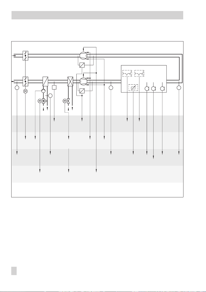
System code number 1
T
T
Ext. ON Ext. speed 2
Set point
T
T
L
TrF
T
F3
(AE2)
BA2
BA1 (BA4)
F4
BE3
BE2
BA2 BA3
Speed 1On/off Speed 2
F1
(AE1)
Y3Y1
(AA)
BE1 BE4
(BE7)
F8 F2
F7
AE4
Specifications in parentheses
can be selected as an alternative
Fig. 3 · Anl 1 (system code no. 1) (ventilation)
Control of the heating and cooling coils
Summer compensation (–> section 6.7)
4
Sequence operation of heating/cooling or overlapping operation (–> section 6.11.8)
4
Fan operation, 2-speed or 0 to 10 V (–> section 6.8 and 6.11.4)
4
F5
(AE3)
(AE3)
26 EB 5477 EN
Page 27
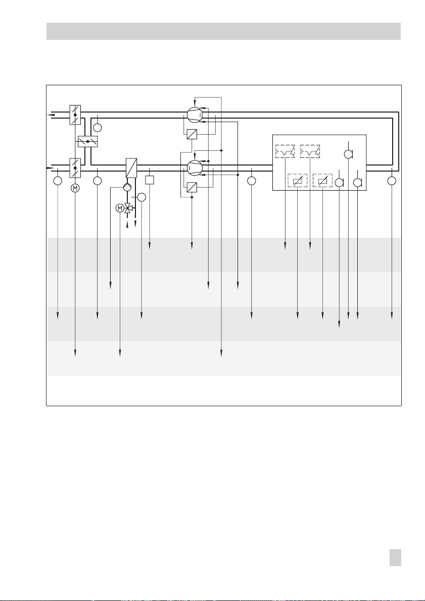
System code number 2
(F7)
T
TT
Systems
Ext. ON Ext. speed 2
Outdoor
Set point
air rate
T
T
T
rF
L
T
T
BE1 BE4
(BE7)
F8 F9 F2
AE4
Specifications in parentheses
can be selected as an alternative
F3
(AE2)
Y2
BE3 BE2
BA1
F7
F4
Y1
BA2 BA3
Speed 1 Speed 2
F1
(AE1)
(AA)
Fig. 4 · Anl 2 (system code no. 2) (ventilation)
Control of mixed air chamber and heating coil
Summer time operation (–> section 6.10.3)
4
Sequence operation of heating/dampers or mixed air temperature control (–> section
4
5.4.2)
Automatic reversal of operating action for mixed air chamber (–> section 5.4.2)
4
Fan operation, 2-speed or 0 to 10 V (–> section 6.8 and 6.11.4)
4
(F7)
F5
(AE3)
(AE3)
EB 5477 EN 27
Page 28
Systems
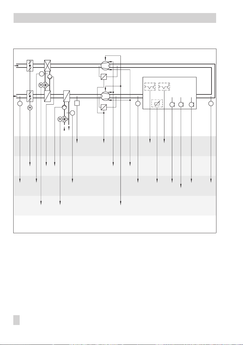
System code number 3
T
Antifreeze required in
HRU.
T
Ext. ON Ext. speed 2
Set point
T
T
T
LrF
T
T
F3
(AE2)
BA2
BA5 BA1
F6
Y2 Y1
BE3 BE2
F4
BA2 BA3
Speed 1 Speed 2
AA
F1
(AE1)
BE1 BE4
(BE7)
F8 F2
Specifications in parentheses
can be selected as an alternative
Fig. 5 · Anl 3 (system code no. 3) (ventilation)
Control of heat recovery unit (HRU) and heating coil
Frost protection for HRU (–> section 7.2.2)
4
Automatic reversal of operating action for HRU configurable (–> section 5.4.2)
4
Fan operation, 2-speed or 0 to 10 V (–> section 6.8 and 6.11.4)
4
AE4
F5
(AE3)
(AE3)
F7
28 EB 5477 EN
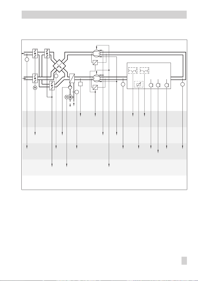
Page 29
Systems
T
Ext. ON Ext. speed 2
F3
(AE2)
BA2
T
T
T
BE3 BE2
BA1
F6
F4
Y1Y2
BA2 BA3
Speed 1 Speed 2
AA
(AE1)
Set point
T
BE1 BE4
(BE7)
F1
F8 F2
Specifications in parentheses
can be selected as an alternative
Fig. 6 · Anl 3 (system code no. 3) with cross-flow heat exchanger (ventilation)
Control of heat recovery unit (HRU) and heating coil
Heat recovery unit designed as a cross-flow heat exchanger
4
Frost protection for HRU (–> section 7.2.2)
4
Automatic reversal of operating action for HRU configurable (–> section 5.4.2)
4
Fan operation, 2-speed or 0 to 10 V (–> section 6.8 and 6.11.4)
4
LrF
T
AE4
F5
(AE3)
F7
T
(AE3)
EB 5477 EN 29
Page 30
Systems
System code number 4
(F7)
T
T
T
Ext. ON Ext. speed 2
rF
Set point T Set point rH
T
T
T
L
T
T
F3
(AE2)
Y2
BE3 BE2
BA1 (BA4)
F4F7
Y1 Y3
BA2 BA3
Speed 1On/off Speed 2
F1
(AE1)
(AA)
BE1 BE4
(BE7)
F8 F9
Specifications in parentheses
can be selected as an alternative
F7
AE4
Fig. 7 · Anl 4 (system code no. 4) (ventilation)
Control of mixed air chamber, heating and cooling coils
Summer compensation (–> section 6.7)
4
Summer time operation (–> section 6.10.3)
4
Sequential operation of heating/dampers/cooling or sequence of heating/cooling and
4
mixed air temperature control
Automatic reversal of operating action for mixed air chamber (–> section 5.4.2)
4
Fan operation, 2-speed or 0 to 10 V (–> section 6.8 and 6.11.4)
4
F5
(AE3)
F2
(AE3)
30 EB 5477 EN
Page 31

System code number 5
T
T
Systems
Ext. ON Ext. speed 2
Set point
T
T
T
L
rF
T
T
BE4
BE1
(BE7)
F8 F2
F3
(AE2)
BA2
BA5 BA1
Y2 Y1 Y3
BE3
F4F6
BE2
BA2BA4 BA3
Speed 1On/off Speed 2
AA
F1
(AE1)
Fig. 8 · Anl 5 (system code no. 5) (ventilation)
Control of heat recovery unit (HRU) as well as heating and cooling coils
Summer compensation (–> section 6.7)
4
Frost protection for HRU (–> section 7.2.2)
4
Automatic reversal of operating action for HRU configurable (–> section 5.4.2)
4
Fan operation, 2-speed or 0 to 10 V (–> section 6.8 and 6.11.4)
4
F7
AE4
F5
(AE3)
(AE3)
EB 5477 EN 31
Page 32

Systems
System code number 6
T
T
Ext. ON Ext. speed 2
rF
Set point T Set point rH
T
T
rF
L
rF
T
T
BE1
BE4
(BE7)
F8 F9 F7
Specifications in parentheses
can be selected as an alternative
F3
(AE2)
BA2
BA1 (BA4)
Y1
BE3
F4
Y2
Y3
BE2
BA2 BA3
Speed 1On/off Speed 2
F1
(AE1)F6(AE2)
(AA)
Fig. 9 · Anl 6 (system code no. 6) (air-conditioning, only humidification)
Control of heating coil, cooling coil and humidification (only humidification)
Two control loops: Temperature and humidity control
4
Only humidification configurable (–> section 5.2)
4
Summer compensation (–> section 6.7)
4
Fan operation, 2-speed or 0 to 10 V (–> section 6.8 and 6.11.4)
4
AE4
(F7)
F5
(AE3)
(AE4)F2(AE3)
32 EB 5477 EN
Page 33

Systems
Antifreeze required
heat exchanger.
T
T
T
T
rF
Ext. ON Ext. speed 2
Set point T Set point rH
Set point T Set point rH
rF
rF
L
T
T
F3
(AE2)
BA2
BE3
BA1
F4
Y1Y3 Y2
BE2
BA2 BA3
Speed 1 Speed 2
(AA)
BE1 BE4
(BE7)
F1
(AE1)F6(AE2)
Note: The position of the cooling coil is not shown
on the display of the controller as here.
Specifications in parentheses
can be selected as an alternative
F8 F9 F7
AE4
(F7)
F5
(AE3)
(AE4)F2(AE3)
Fig. 10 · Anl 6 (system code no. 6) (air-conditioning, humidifying and dehumidifying)
Control of cooling and heating coils and humidification (humidifying and dehumidifying)
Two control loops: Temperature and humidity control
4
Humidification or humidifying and dehumidifying operation configurable (–> section 5.2)
4
Summer compensation (–> section 6.7)
4
Fan operation, 2-speed or 0 to 10 V (–> section 6.7 and 6.11.4)
4
EB 5477 EN 33
Page 34

Systems
System code number 7
T
T
Ext. ON Ext. speed 2
Set point
L
rF
T
T
BE2
BA2
F3
(AE2)
BA2(BA4) BA3
Speed 1On/off Speed 2
F1
(AE1)
(AA)Y3
Fig. 11 · Anl 7 (system code no. 7) (ventilation)
Cooling coil control
Summer compensation (–> section 6.7)
4
Fan operation, 2-speed or 0 to 10 V (–> section 6.8 and 6.11.4)
4
BE1 BE4
(BE7)
F8 F2
F7
Specifications in parentheses
can be selected as an alternative
AE4
F5
(AE3)
(AE3)
34 EB 5477 EN
Page 35

System code number 8
T
Systems
Ext. ON Ext. speed 2
rF
Set point T Set point rH
T
T
T
rF
L
rF
T
T
BE3
BA1
F3
(AE2)
Y2
Fig. 12 · Anl 8 (system code no. 8) (air-conditioning, only humidification)
Y1
(BA4)
F4
BE2
BA2 BA3
Speed 1Speed 2
F1
(AE1)F6(AE2)
AAY3
BE1 BE4
(BE7)
F8 F9 F7
Specifications in parentheses
can be selected as an alternative
(F7)
AE4
F5
(AE3)
Control of mixed air chamber, heating coil, cooling coil and humidification
Two control loops: Temperature and humidity control
4
Humidification or humidifying and dehumidifying operation configurable (–> section 5.2)
4
Summer compensation (–> section 6.7)
4
Summer time operation (–> section 6.10.3)
4
Automatic reversal of operating action for mixed air chamber (–> section 5.4.2)
4
Fan operation, 2-speed (–> section 6.8 and 6.11.4)
4
(AE4)F2(AE3)
EB 5477 EN 35
Page 36

Systems
4.1 System code number 9
T
F3
(AE2)
BA2
Y2 Y1
BA5 BA1
Antifreeze required
heat exchanger.
T
T
BE3
(BA4)
F4
BE2
BA2 BA3
Speed 1On/off Speed 2
(AE1)F6(AE2)
AAY3
T
F1
Ext. ON Ext. speed 2
Set point T Set point rH
rF
BE1 BE4
(BE7)
F8 F9 F7
Specifications in parentheses
can be selected as an alternative
AE4
rF
L
(F7)
(AE3)
Fig. 13 · Anl 9 (system code no. 9) (air-conditioning, only humidification)
Control of heat recovery unit (HRU), heating coil, cooling coil and humidification
T
F5
(AE4)F2(AE3)
rF
T
Two control loops: Temperature and humidity control
4
Humidification or humidifying and dehumidifying operation (–> section 5.2)
4
Summer compensation (–> section 6.7)
4
Automatic reversal of operating action for HRU configurable (–> section 5.4.2)
4
Fan operation, 2-speed (–> section 6.8 and 6.11.4)
4
36 EB 5477 EN
Page 37

Control methods and system components
5 Control methods and system components
5.1 Ventilation and temperature control in air-conditioning systems
In temperature control, various control methods are differentiated between: Supply air tem
perature control, exhaust air temperature control, exhaust air cascade control, room and
room cascade control.
5.1.1 Supply air temperature control
The sensor input F1 is the control variable input by default. Alternatively, the supply air tem
perature can also be guided over the analog input AE1 to the controller.
The supply air temperature is controlled by a PID algorithm with an adjustable
temperature set point
. Depending on the system code number, the temperature control loop
has between 1 and 3 sequence outputs that are adapted to the dynamics of the correspond
ing system components by means of the
KP, T
and
T
N
control parameters. Functions such as
V
return air temperature limit, summer compensation, manual set point correction or condensation detection can shift the set point. The supply air can be controlled dependent on the outdoor temperature.
Functions
Control method Supply air control (–> page 17)
Sensor F1, supply air temperature
Assignment of inputs AE1 to AE4
Parameters
Supply air temperature set point 22 °C 0 to 50 °C
K
P
T
N
T
V
or
WE Configuration
Fb1 = ON or
OFF
Fb18 = ON,
WE Range of values
0.5 0.1 to 99.9
60 sec 1 to 999 sec
– – – – – – to 999 sec
option
: AE1F1
Supply air
-
-
5.1.2 Exhaust air temperature control
The sensor input F2 is the control variable input by default. Alternatively, the exhaust air tem
perature can also be guided over the analog input AE3 to the controller.
The exhaust air temperature is controlled by a PID algorithm with an adjustable
temperature set point
. Depending on the system code number, the temperature control loop
has between 1 and 3 sequence outputs that are adapted to the dynamics of the correspond
ing system components by means of the
KP, T
and
T
N
control parameters.
V
Exhaust air
EB 5477 EN 37
-
-
Page 38

Control methods and system components
Functions such as return air temperature limit, summer compensation, manual set point cor
rection or condensation detection can shift the set point.
Functions
Control method Exhaust air control (–> page 17)
Sensor F2, exhaust air temperature
assignment of inputs AE1 to AE4
Parameters
Exhaust air temperature set point 22 °C 0 to 40 °C
K
P
T
N
T
V
or
WE Configuration
OFF
WE Range of values
0.5 0.1 to 99.9
60 sec 1 to 999 sec
– – – – – – to 999 sec
Fb2 = ON or
Fb18 = ON,
option:
AE3F2
5.1.3 Exhaust air temperature cascade control
The sensor input F2 is the control variable input for the exhaust air temperature and the sensor input F1 is the control variable input for the supply air temperature by default. Alternatively, the exhaust air temperature can also be guided over the analog input AE3 and the
supply air temperature over the analog input AE1 to the controller.
The exhaust air temperature control loop is implemented as a P control loop with adjustable
Exhaust air temperature set point
perature is controlled by a PID control algorithm with adjustable
slave loop.
Depending on the system code number, the supply air temperature control loop
has between 1 and 3 sequence outputs that are adapted to the dynamics of the corresponding system components by means of the
Supply air temperature minimum limit
the set point shift which arises when the exhaust air temperature control loop takes influence
on the supply air temperature control loop:
Each deviation in exhaust air temperature by the amount x causes a shift of the supply air
temperature set point by the amount x multiplied by the parameter
master loop
x = Exhaust air temperature set point – Exhaust air temperature actual value
4
Temperature set point of slave loop
4
.
Temperature set point of slave loop
Note!
If the calculated set point is not within the limit, the minimum or maximum limit applies as
the new set point.
and
KPTemperature of the master loop
KP, T
and
T
N
and
Supply air temperature maximum limit -
calculated
=
+ x ·
KPTemperature master loop
control parameters. The parameters -
V
. The supply air tem-
Temperature set point of
restrict
KPTemperature of the
-
38 EB 5477 EN
Page 39

Control methods and system components
Shifts in the set point which are caused by manual set point correction, return air tempera
ture limit, summer compensation or by condensation detection, have unrestricted effects on
the exhaust air temperature set point.
Functions
Control method Exhaust air cascade control (–> page 17)
Sensor F1, supply air temperature
assignment of inputs AE1 to AE4
Sensor F2, exhaust air temperature
assignment of inputs AE1 to AE4
Parameters
Exhaust air temperature set point 22 °C 0 to 40 °C
Temperature set point of the slave loop 22 °C 0 to 50 °C
KPTemperature master loop 1 0.1 to 99.9
Supply air temperature minimum limit 18 °C 0 °C up to Supply air temp. maximum limit
Supply air temperature maximum limit 26 °C Supply air temp. minimum limit up to 50 °C
K
P
T
N
T
V
or
or
WE Configuration
Fb1 = ON or
OFF
Fb18 = ON,
Fb2 = ON or
OFF
Fb18 = ON,
WE Range of values
0.5 0.1 to 99.9
60 sec 1 to 999 sec
– – – – – – to 999 sec
option
option:
: AE1F1
AE3F2
5.1.4 Room temperature control
The sensor input F5 is the control variable input by default. Alternatively, the room temperature can also be guided over the analog input AE3 to the controller.
The room temperature is controlled by a PID algorithm with an adjustable
set point
. Depending on the system code number, the temperature control loop has between
1 and 3 sequence outputs that are adapted to the dynamics of the corresponding system
KP, T
and
T
components by means of the
N
control parameters. Functions such as return air
V
temperature limit, summer compensation, manual set point correction or condensation detec
tion can shift the set point.
Functions
Control method Room control (–> page 17)
Sensor F5, room temperature
assignment of inputs AE1 to AE4
or
WE Configuration
Fb5 = ON or
OFF
Fb18 = ON, option AE3F5
Room temperature
-
EB 5477 EN 39
Page 40

Control methods and system components
Parameters
Room temperature set point 22 °C 0 to 40 °C
K
P
T
N
T
V
WE Range of values
0.5 0.1 to 99.9
60 sec 1 to 999 sec
– – – – – – to 999 sec
5.1.5 Room temperature cascade control
The sensor input F5 is the control variable input for the room temperature and the sensor
4
input F1 is the control variable input for the supply air temperature by default. Alterna
tively, the room temperature can also be guided over the analog input AE3 and the sup
ply air temperature over the analog input AE1 to the controller.
The room temperature control loop is implemented as a P control loop with adjustable
Room temperature set point
is controlled by a PID control algorithm with adjustable
Depending on the system code number, the temperature control loop has between 1
loop.
and 3 sequence outputs that are adapted to the dynamics of the corresponding system
components by means of the
air temperature minimum limit
point shift which arises when the room temperature control loop takes influence on the
supply air temperature control loop: each deviation in room temperature by the amount
x causes a shift of the supply air temperature set point by the amount x multiplied by the
parameter
x =
4
Supply air temperature set point
4
KPTemperature master loop
Room temperature set point
Supply air temperature set point + x · KPTemperature master loop
Note!
If the calculated set point is not within the limit, the minimum or maximum limit applies as
the new set point.
Shifts in the set point which are caused by manual set point correction, return air tempera
ture limit, summer compensation or by condensation detection, have unrestricted effects on
the room temperature set point.
Functions
Control method Room cascade control (–> page 17)
Sensor F1, supply air temperature
assignment of inputs AE1 to AE4
Sensor F5, room temperature
assignment of inputs AE1 to AE4
and
KPTemperature master loop
. The supply air temperature
Temperature set point of the slave
KP,T
and
T
N
and
Supply air temperature maximum limit -
control parameters. The parameters -
V
Supply
restrict the set
.
– Room temperature actual value
calculated
or
or
=
WE Configuration
Fb1 = ON or
OFF
Fb18 = ON,
Fb5 = ON or
OFF
Fb18 = ON,
option:
option:
AE1F1
AE3F5
-
-
-
40 EB 5477 EN
Page 41

Control methods and system components
Parameters
Room temperature set point 22 °C 0 to 40 °C
Temperature set point of the slave loop 22 °C 0 to 50 °C
KPTemperature master loop 1.0 0.1 to 99.9
Supply air temperature minimum limit 18 °C 0 °C up to supply air temp. maximum limit
Supply air temperature maximum limit 26 °C Supply air temp. minimum limit up to 50 °C
K
P
T
N
T
V
WE Range of values
0.5 0.1 to 99.9
60 sec 1 to 999 sec
– – – – – – to 999 sec
5.2 Humidity control in air-conditioning systems (Anl 6, 8 and 9)
In humidity control, various control methods are differentiated between: Supply air, exhaust
air/room temperature control, exhaust air cascade control and room cascade control.
5.2.1 Supply air humidity control
The sensor input F6 is the control variable input by default. Alternatively, the analog input
AE2 can be used.
The supply air humidity is controlled by a PID control algorithm with an adjustable
humidity set point
. The humidity control loop can be used for just humidifying or for humidifying and dehumidifying depending on the control method. In humidifying and dehumidifying mode, the cooling coil is controlled in sequence to the humidifier.
The requirements of the humidity control loop for dehumidifying and the temperature control
loop for cooling are converted internally into a common control signal Y3 for the cooling
coil. Each output can be adapted to the dynamics of the corresponding system components
KP, T
and
T
by means of the
N
control parameters that are adjustable.
V
A manual set point correction has an unrestricted effect on the control by the shifting the set
point.
Supply air
Functions
Control method Supply air control (–> page 17)
Sensor F6, supply air humidity
assignment of inputs AE1 to AE4
or
WE Configuration
Fb6 = ON or
OFF
Fb18 = ON,
option:
AE2F6
EB 5477 EN 41
Page 42

Control methods and system components
Parameters
Supply air humidity set point 50 %rH 0 to 100 %rH
K
P
T
N
T
V
WE Range of values
0.5 0.1 to 99.9
60 sec 1 to 999 sec
– – – – – – to 999 sec
5.2.2 Exhaust air/room humidity control
The sensor input F7 is the control variable input by default. Alternatively, the analog input
AE4 can be used.
The exhaust air or room humidity control is implemented as a PID control algorithm with ad
justable
Exhaust air humidity set pointorRoom humidity set point
can be used just for humidifying or for humidifying and dehumidifying depending on the
control method. In humidifying and dehumidifying mode, the cooling coil is controlled in se
quence to the humidifier.
The requirements of the humidity control loop for dehumidifying and the temperature control
loop for cooling are converted internally into a common control signal Y3 for the cooling
coil. Each output can be adapted to the dynamics of the corresponding system components
KP, T
and
T
by means of the
N
control parameters that are adjustable. A manual set point
V
correction has an unrestricted effect on the control by the shifting the set point.
Functions
Control method Exhaust air/room control (–> page 17)
Sensor F7, exhaust air/room control
assignmet of inputs AE1 to AE4
Parameters
Exhaust air humidity set point
room humidity set point
K
P
T
N
T
V
or
or
WE Configuration
OFF
WE Range of values
50 %rH
50 %rH
0.5 0.1 to 99.9
60 sec 1 to 999 sec
– – – – – – to 999 sec
Fb7 = ON or
Fb18 = ON,
0 to 100 %rH
0 to 100 %rH
. The humidity control loop
option:
AE4F7
-
-
5.2.3 Exhaust air or room humidity cascade control
The sensor input F7 is the control variable input for exhaust air or room humidity and the
sensor input F6 is the control variable input for supply air humidity by default. Alternatively,
the analog input AE4 can be used for exhaust air or room humidity or the analog input AE2
for the supply air humidity.
42 EB 5477 EN
Page 43

Control methods and system components
The master loop has a P control response with adjustable
Room humidity set point
by a PID control algorithm with adjustable
and
Kp Humidity master loop
Humidity set point of the slave loop
Exhaust air humidity set point
. The supply air control is implemented
. The humidity
control loop can be used either just for humidifying or for humidifying and dehumidifying by
involving the cooling coil in sequence to the humidifier. The requirements of the humidity
control loop for dehumidifying and the temperature control loop for cooling are converted
internally into one common control signal Y3 for the cooling unit. Each output can be adap
KP,T
ted to the dynamics of the corresponding system components by means of the
and
N
control parameters that are adjustable. The set point of the supply air humidity control loop
is shifted depending on the system deviation in the exhaust air or room humidity control
loop:
Each deviation in humidity by the amount x shifts the supply air humidity set point by the
amount x multiplied by the parameter
and
humidity minimum limit
x = Exhaust air humidity set point – Exhaust air humidity actual value
4
Humidity set point of the slave loop
4
Supply air humidity maximum limit
KPHumidity master loop
calculated
=
within the range
.
Supply air
Humidity set point of the master loop + x · KPTemperature of the master loop
Note!
If the calculated set point is not within the limit, the minimum or maximum limit applies as
the new set point.
Functions
Control method Exhaust air/room cascade control (–> page 17)
Sensor F6, supply air humidity
assignment of inputs AE1 to AE4
Sensor F7, exhaust air or room humidiy
assignment of inputs AE1 to AE4
Parameters
Exhaust air humidity set point
room humidity set point
Humidity set point of the slave loop 50 %rH 0 to 100 %rH
KPHumidity master loop 1.0 0.1 to 99.9
Supply air humidity minimum limit 40 %rH 0 %rF up to supply air humidity maximum limit
Supply air humidity maximum limit 60 %rH Supply air humidity min. limit up to 100 %rH
K
P
T
N
T
V
or
or
WE Configuration
Fb6 = ON oder
OFF
Fb18 = ON,
OFF
Fb7 = ON oder
Fb18 = ON,
0 to 100 %rH
0 to 100 %r
or
WE Range of values
50 %rH
50 %rH
0.5 0.1 to 99.9
60 sec 1 to 999 sec
– – – – – – to 999 sec
option:
option:
AE2F6
AE4F7
or
-
T
V
EB 5477 EN 43
Page 44

Control methods and system components
5.3 Inputs
The assignment of the inputs depends on the system code number and the control method
(–> section 4). Sensors that are required for the selected control methods are always acti
vated. You must determined separately all the other sensors as well as the functions of the bi
nary inputs by configuring them (–>section 2). Alternatively, you can also assign up to four
analog inputs (0 to 10 V) to some of the resistance sensors. The analog inputs are suitable
for active temperature, humidity and air quality sensors.
Functions
Assignment of inputs
AE1 to AE4
WE Configuration
OFF Fb18 = ON
AE_--: Not asssigned AE1F1: Supply air temp. F1
AE3F2: Exhaust air temp. F2 AE2F3: Outdoor temperature F3
AE3F5: Room temperature F5 AE2F6: Supply air humidity F6
AE4F7: Exh. air/room humidity AE4L: Air quality L
MIN: Lower measuring range value
MAX: Upper measuring range value
5.4 Outputs
5.4.1 Heating coil
The heating coil is controlled from the control output Y1. The heating coil control is imple-
and
TV.
mented by a PID control algorithm with the adjustable parameters K
P,TN
ing action of the control output Y1 can be reversed. The default setting of the operating action: heating capacity 0 to 100 % = 0 to 10 V.
An electric air heater can be controlled via the binary output BA5 subject to Y1 (–> sec
tion 6.11.12).
The operat-
-
-
Control signal
Y1
– System deviation +
Fig. 14 · Output signal in Anl. 0
44 EB 5477 EN
Controlled variable
Page 45

Control methods and system components
Functions
Operating action Y1 OFF Fb21
Parameters
KPHeating coil 0.5 0.1 to 99.9
TNHeating coil 60 sec 1 to 999 sec
TVHeating coil – – – – – – to 999 sec
WE Configuration
WE Range of values
5.4.2 Mixed air chamber
Mixed air chamber in sequential operation
The mixed air chamber is controlled from the Y2 output which can be adapted to the dynam
ics of the mixed air chamber by means of the parameters
air chamber
TvMixed air chamber.
The parameter
and
tees an minimum proportion of outdoor air. The operating action of the control output Y2
can be reversed. The default setting is an outdoor air rate of 0 to 100 % which corresponds
to a control signal of 0 to 10 V. By activating Fb22, the operating action is reversed: the outdoor air rate 0 to 100 % then corresponds to 10 to 0 V. On feedforwarding the outdoor
temperature, the summer time operation function is taken into account (–> section 6.10.3).
By additionally feedforwarding the exhaust air temperature, the automatic reversal of the
operating action takes effect.
If the operating action of the control output Y2 is automatically reversed due to changing
temperatures, while the control is in the sequence range Y1 or Y3, the mixed air chamber is
then reversed with a constant changing rate of 15 % per minute. If there is a considerable
difference in temperature between exhaust air and extract air due to the heat given off by
the fan, the extract air temperature can also be selected as the measured variable in place of
the exhaust air temperature.
KpMixed air chamber,TNMixed
Minimum outdoor air rate
guaran-
-
Note:
The proportion of outdoor air can be suppressed during the warm-up phase with Fb43 = ON.
Functions
Sensor F7, mixed air or extract air
temperature
Operating action Y2 OFF Fb22
Circ. air mode after system start-up OFF Fb43 (not with supply air control)
WE Configuration
Fb7 = ON,
Fb7 = OFF,
option:
SEQ (with extract air sensor)
option:
SEQ (without extract air sensor)
EB 5477 EN 45
Page 46

Control methods and system components
Control
signal
Control
signal
Without outdoor air and exhaust air/
extract air temperature feedforwarding
Y1 Y2 Y3
– System deviation +
With outdoor temperature
feedforwarding
Y1 Y2 Y3
– System deviation +
Control variable
Control variable
Outdoor temperature
Control
signal
With outdoor air and exhaust air/extract
air temperature feedforwarding
tA > t Ab
Y2
Y1
Fig. 15 · Various output signals, e.g. in system code number 4
Parameters
WE Range of values
KPMixed air chamber 0.5 0.1 to 99.9
TNMixed air chamber 60 sec 1 to 999 sec
TVMixed air chamber – – – – – – to 999 sec
Minimum outdoor air rate 20 % 0 to 100 %
tA < t Ab
Control variable
Outdoor temperature
Y3
Independent mixed air temperature control
The independent mixed air temperature control is implemented by a PID control algorithm
with adjustable
Mixed air temperature set point.
the mixed air chamber with the parameters
and
TVMixed air chamber
. The parameter
The output Y2 is adapted to the dynamics of
KPMixed air chamber,TNMixed air chamber
Minimum outdoor air rate
guarantees a mini
mum proportion of outdoor air.
The operating action of the control output Y2 can be reversed. The default setting is an out
door air rate of 0 to 100 % which correspond to a control signal of 0 to 10 V. By activating
the function block Fb22, the operating action is reversed: an outdoor air rate 0 to 100 %
corresponds to 10 to 0 V. On feedforwarding the outdoor temperature, the summer time op
eration function is taken into account (–> section 6.10.3). By additionally feedforwarding the
exhaust temperature, the automatic reversal of the operating action takes effect.
46 EB 5477 EN
-
Page 47

Control
signal
Without outdoor and exhaust air temperature
feedforwarding
Y2 Y1
Y3
Control methods and system components
– System deviation
With outdoor temperature feedforwarding
Outdoor temperature
+
Control variable
With outdoor and exhaust air temperature
feedforwarding
Control
Y2
Y1
– System +
deviation
signal
Y3
Control variable
Outdoor temperature
tA > t Ab
Y2
tA < tAb
Y1
– System +
deviation
Y3
Control variable
Fig. 16 · Various output signals, e.g. in system code number 4
Note!
The proportion of outdoor air can be suppressed during the warm-up phase with Fb43 = ON.
Functions
Sensor F7, mixed air or extract air temperature
Operating action Y2 OFF Fb22
Circulating air mode after system start-up OFF Fb43 (not with supply air control)
Parameters
KPMixed air chamber 0.5 0.1 to 99.9
TNMixed air chamber 60 sec 1 to 999 sec
TVMixed air chamber – – – – – – to 999 sec
Minimum outdoor air rate 20 % 0 to 100 %
Mixed air temperature set point 18 °C 10 to 30 °C
WE Configuration
Fb7 = ON,
option:
WE Range of values
mixed air sensor
EB 5477 EN 47
Page 48

Control methods and system components
Outdoor temperature-controlled mixed air chamber
For the outdoor temperature-controlled mixed air chamber, two outdoor temperature basic
values are determined with the parameters
perature is smaller
and
100 % outdoor when the outdoor temperature is greater
in a characteristic curve for controlling the mixed air chamber. The parameter
door air rate
guarantees the required minimum proportion of the outdoor air.
Minimum outdoor air rate when the outdoor tem
which result
Minimum out
The summer time operation (–> section 6.10.3) is always available with this operation mode.
Control signal
Y2 %
Outdoor temperature
Fig. 17 · Outdoor temperature-controlled mixed air chamber
Note:
The proportion of outdoor air can be suppressed during the warm-up phase with Fb43 = ON.
-
-
Functions
Sensor F7, mixed air or extract air temperature
Operating action Y2 OFF Fb22
Circulating air mode after system start-up OFF Fb43 (not with supply air control)
Parameters
Min. outdoor air rate when the outdoor
temperature is smaller
100 % outdoor air when the outdoor temp. is greater 18 °C –10 to 50 °C
Minimum outdoor air rate 20 % 0 to 100 %
WE Configuration
Fb7 = OFF,
WE Range of values
0 °C –10 to 50 °C
option:
AT
5.4.3 Heat recovery unit (HRU)
The heat recovery unit is controlled from the control output Y2. It is implemented by a PID
control algorithm with the parameters
48 EB 5477 EN
KPHRU,TNHRU
and
TVHRU.
Page 49

Control methods and system components
Control
signal
Control variable
Fig. 18 · Output signals, e.g. in system code number 6 (humidifier only)
The operating action of the control output Y2 can be reversed.
The default setting is a heat recovery capacity of 0 to 100 % which corresponds to a control
signal from 0 to 10 V. By activating the function block Fb22, the operating action is re
-
versed: HRU capacity 0 to 100 % then corresponds to 10 to 0 V.
If the measured outdoor temperature and exhaust air temperature are available, the auto-
matic reversal of the operating action for the heat recovery unit can be activated with
Fb41 = ON.
Functions
Operating action Y2 OFF Fb22
Automatic reversal of the operating action OFF Fb41
Parameters
KPHRU 0.5 0.1 to 99.9
TNHRU 60 sec 1 to 999 sec
TVHRU – – – – – – to 999 sec
WE Configuration
WE Range of values
5.4.4 Cooling coil
The cooling coil is controlled from the control output Y3. It is implemented by a PID control
algorithm with the parameters K
Cooling coil,TNCooling coil
P
system code numbers 6, 8 and 9, the demands made by the humidity control loop for hu
midifying or the temperature control loop for cooling are converted internally into one com
mon control signal Y3 for the cooling coil. The operating action of the control output Y3 can
be reversed. The default setting is a cooling capacity of 0 to 100 % which corresponds to a
control signal from 0 to 10 V.
By activating the function block Fb23, the operating action is reversed: the cooling capacity
0 to 100 % then corresponds to 10 to 0 V.
and
TVCooling coil.
In the
-
EB 5477 EN 49
-
Page 50

Control methods and system components
Control
signal
Humidifying
– System deviation +
Fig. 19 · Output signals, e.g. in system code number 6 (humidifying and dehumidifying)
Dehumidifying
Heating
- System deviation +
Cooling
Control
variable
Cooling can also be controlled using an on/off signal which is issued at the binary output
BA4 (–> section 6.11.7). Control of a chiller is likewise possible (–> section 6.11.8).
Functions
Operating actionY3 OFF Fb23
Parameters
KPCooling coil 0.5 0.1 to 99.9
TNCooling coil 60 sec 1 to 999 sec
TVCooling coil – – – – – – to 999 sec
WE Configuration
WE Range of values
5.5 Humidifier
The humidifier is controlled in system code number 6 from the control output Y2 and in system
code numbers 8 and 9 from the analog output AA. The allocation of the control output Y2 to
the humidifier shown in the controller display does not apply to system code numbers 8 and 9!
The humidifier control is implemented by a PID control algorithm with the parameters
,
midifier
TNHumidifier
and
TVHumidifier
.
The operating action of the control output Y2 can be reversed. The default setting is a humid
ifier capacity of 0 to 100 % which corresponds to a control signal of 0 to 10 V. By activating
the function block Fb22, the operating action is reversed: a humidifier capacity 0 to 100 %
then corresponds to 10 to 0 V.
The operating action at the analog output AA cannot be reversed.
Function
Operating action Y2 OFF Fb22
WE Configuration
KPHu
-
-
50 EB 5477 EN
Page 51

Control methods and system components
Parameters
KPHumidifier 0.5 0.1 to 99.9
TNHumidifier 60 sec 1 to 999 sec
TVHumidifier – – – – – – to 999 sec
Control
signal
Fig. 20 · Output signals, e.g. in system code number 6 (humidifier only)
WE Range of values
Controlled variable
5.6 Fans with variable speed
The analog output AA can be used to control the speed of the fans and the air volume based
on the air quality. If the air quality falls below the parameter
ume is increased based on the
When an exhaust air cascade control or a room temperature cascade control is used, the
controller can be programmed so that the air volume is increased when the supply air temperature limit is reached to eliminate the system deviation as quickly as possible. This function has priority over the air quality control. After the system deviation has been balanced
out, the air quality control is enabled again. The function is activated when the
change K
Example:
The supply air temperature has reached its minimum permissible value at 50 % air volume
(y
AA
Exhaust air temperature set point
4
Exhaust air temperature = 24 °C
4
Factor of change K
4
YYXDK
4
(XD is the percentage error in relation to the measuring range. Its maximum limit is 10 %)
is selected greater than 0.
P
= 50 %).
P
AA P
neu
=+ ⋅
=+°−°÷°⋅ ⋅50 24 22 40 100 5%%
= 75%
CC C
()
Minimum air volume flow
= 22 °C
= 5
Air quality set point
.
.
, the air vol-
Factor of
EB 5477 EN 51
Page 52

Control methods and system components
The system runs at an air volume of 75 % to reduce the excess temperature more quickly.
The air quality control is implemented by a PI control algorithm with the parameters
and
quality control
TNAir quality control.
KPAir
The operating action of the air quality input can be reversed. The default setting is an air
quality of 0 to 100 % which corresponds to an input signal of 0 to 10 V. L 0 means an insuf
ficient air quality.
By activating the function block Fb24, the operating action is reversed: air quality 0 to
100 % then corresponds to 10 to 0 V. As a result, L 0 means a very good air quality.
Functions
Assignment of inputs AE1 to AE4 OFF
Request for externally required signal OFF Fb20 = OFF
Variable air volume control over AA OFF
Operating action L OFF Fb24
Parameters
Air quality set point 50 0 to 100
KPAir quality control 0.5 0.1 to 99.9
TNAir quality control 60 sec 1 to 999 sec
WE Configuration
Fb18 = ON,
Fb39 = ON
25 %
0.0
* Factor of change with cascade control only
WE Range of values
MIN AA (minimum air volume)/0to100%
(Factor of change) / 0.0 to 10.0*
K
P
option:
AE4L
-
52 EB 5477 EN
Page 53

Control functions
6 Control functions
6.1 Supply air temperature limit
The intention of the supply air temperature limit is to reduce the draft when supply air that is
fairly cold is blown in. The temperature range within which the supply air temperature may
vary is determined by the parameters
temperature maximum limit
. If the supply air temperature is the control variable, i.e. for sup
Supply air temperature minimum limit
ply air temperature control or exhaust air or room temperature cascade controI, the control
ler only permits set point shifts within this range.
If F1 or AE1 is just used as a limit input, i.e. for exhaust air or room temperature control, this
deviation is included in the control when the supply air temperature exceeds or fall below the
limit values, to counter any further drifting of the supply air temperature.
Functions
Sensor F1, supply air temperature
assignment of inputs AE1 to AE4
Parameters
Supply air temperature minimum limit 18 °C 0 °C up to supply air temp. maximum limit
Supply air temperature maximum limit 26 °C Supply air temp. minimum limit up to 50 °C
or
WE Configuration
Fb1 = ON
OFF
Fb18 = ON,
WE Range of values
option:
AE1F1
and
Supply air
-
-
6.2 Supply air humidity limit
For exhaust air or room humidity control, the parameters
and
Supply air humidity maximum limit
restrict the humidity range within which the supply
air humidity may vary. If it leaves this range, the deviation is included in the system deviation
to prevent any further drifting of the supply air humidity.
The main purpose of the supply air humidity maximum limit is to prevent condensation form
ing in the supply air duct.
Functions
Sensor F6, supply air humidity
assignment of outputs AE1 to AE4
Parameters
Supply air humidity minimum limit 40 %rH 0 %rH up to supply air humidity max. limit
Supply air humidity maximum limit 60 %rH Supply air humidity max. limit up to 100 %rH
or
WE Configuration
Fb6 = ON
OFF
Fb18 = ON,
WE Range of values
Supply air humidity minimum limit
option:
AE2F6
EB 5477 EN 53
-
Page 54

Control functions
6.3 Return air temperature limit
The temperature range within which the return air temperature may vary is determined by
the parameters
. If the return air temperature moves towards these limits, the set point is corrected (for
limit
the cascade control, the set point of the exhaust air or room temperature). In the range
turn air temperature minimum limit
Return air temperature limit factor
by the
falls below. In the range
ered by the amount x multiplied by the
that the return air temperature exceeds.
Return air temperature falls below limit:
x =
4
4
4
4
Return air temperature minimum limit–Actual return air temperature
Supply air temperature set point
Supply air temperature set point
Return air temperature exceeds limit:
x =
Actual return air temperature–Return air temperature maximum limit
Supply air temperature set point
Supply air temperature set point
The supply air temperature limit function has priority.
Functions
Sensor F4,
Return air temperature, heating coil
Parameters
Return air temperature minimum limit 20 °C 0 °C up to return air temperature maximum limit
Return air temperature maximum limit 70 °C Return air temperature minimum limit up to 100 °C
Return air temperature limit factor 1 0 to 10
Return air temperature minimum limit
, the set point is directly raised by the amount x multiplied
for every amount x that the return air temperature
Return air temperature maximum limit
Return air temperature limit factor
calculated
+ x ·
calculated
– x ·
=
Return air temperature limit factor
=
Return air temperature limit factor
WE Configuration
WE Range of values
and
Fb4 = ON
Return air temperature maximum
, the set point is directly low
for every amount x
Re
-
-
6.4 Variable return air temperature maximum limit
If an outdoor temperature sensor exists, it is possible to vary return air temperature limit. The
following parameters apply for the upper variable limit of the return air temperature:
air temperature maximum limit coordinate 1, Outdoor temperature coordinate 1, Return air
temperature maximum limit coordinate 2, Outdoor temperature coordinate 2.
The gray shaded area in Fig. indicates the permissible return air temperatures.
54 EB 5477 EN
Return
Page 55

Control functions
If the
Return air temperature maximum limit
is exceeded by the amount x, the set point (for
cascade control, the set point of the exhaust air or room temperature) is reduced by the
amount x multiplied with the
x = Actual return air temperature – Return air temperature maximum limit
4
Return air temperature limit factor.
Note! The permissible return air temperature maximum limit depends on the outdoor tem
perature (see Fig. )
Supply air temperature set point
4
Supply air temperature set point
calculated
– x ·
=
Return air temperature limit factor
The supply air temperature limit has priority.
Parameters
Return air temperature minimum limit 20 °C 0°C up to return air flow temp. maximum limit
Return air flow temperature maximum li
mit, coordinates 1 and 2
Return air temperature limit factor 1 0 to 10
Outdoor temperature coordinate 1 5 °C –50 to 20 °C
Outdoor temperature coordinate 2 20 °C –50 to 20 °C
WE Range of values
70 °C Return air temperature minimum limit up to 100 °C
-
6.5 Sustained room temperature
-
If a room temperature sensor is connected, the
Sustained room temperature
is monitored
when the system is in the reduced operation mode. If the room temperature falls below this
limit value, at first the system start-up function is initiated. Then the supply air temperature is
controlled constantly to the set point
the room temperature has reached the
Supply air temperature maximum limit
Sustained room temperature
(plus 2 °C), the sustained
(minus 1 °C). If
room temperature function and usually the operation of the entire system is ended.
Functions
Sensor F5, room temperature Fb5 = ON
Parameters
Room sustained temperature 15 °C 0 to 20 °C
Supply air temperature minimum limit 26 °C Supply air temperature minimum limit up to 50 °C
WE Configuration
WE Range of values
EB 5477 EN 55
Page 56

Control functions
Set point °C
30
26
22
Outdoor
temperature °C
Fig. 21 · Summer compensation
6.6 Night purge
During the times-of-non-use, the night air can be used to cool the rooms under certain conditions: the fan operation (speed 1) is enabled and, if necessary, the mixed air chamber is reversed to 100 % outdoor air rate. The night purge is only enabled when the summer deacti-
vation function (–> section 6.10.2) is active and, in addition, the following conditions are
met:
Room temperature is greater than the room temperature limit
4
and
Temperature difference between room temperature and the outdoor temperature is
4
greater than the value set under
Temperature difference to outdoor temperature
The night purge can be set to start at 0:00 hrs at the earliest, 4:00 hrs at the latest –
depending on the programmed system times-of-use. The controller must be programmed to
start the night purge at the latest possible point in time. It is limited to two hours at the maxi
mum. If the room temperature falls below the room temperature limit value determined under
Finish night purge (STOP),
the night purge is ended early.
Enable night purge (START
)
-
Functions
Night purge OFF
WE Configuration
24 °C
18 °C
5 °C
56 EB 5477 EN
Fb10 = ON
START / STOP up to 50 °C
STOP / 10 °C up to START
Temperature difference to outdoor temp./0to50°C
Page 57

Control functions
6.7 Summer compensation
The function is basically available for all systems with a cooling coil (Anl 1, Anl 4 to Anl 9):
This summer compensation function lets the temperature set points for supply air, exhaust air
and room be shifted in a linear manner by means of two coordinates. For this purpose, the
following parameters must be defined:
Summer compensation when the outdoor temperature is greater
4
perature onwards, the temperature set point is raised
Set point at an outdoor temperature of 32 °C
4
curve.
Example:
In an air-conditioning system, the supply air temperature set point should be raised when the
outdoor temperature is greater than 25 °C. At 32 °C, the supply air temperature set point
should be 26 °C.
Supply air temperature set point = 22 °C
4
Summer compensation when the outdoor temperature is greater = 25 °C
4
Set point at an outdoor temperature of 32 °C
4
determines the gradient of the characteristic
= 26 °C
: from this outdoor tem
-
Parameters
Summer compensation when the
outdoor temperature is greater
Set point at an outdoor temperature of 32 °C 26 °C 0 to 40 °C
WE Range of values
26 °C –50 to °C
6.8 Fan operation dependent on room temperature/room humidity
You can select this function with room temperature control, room temperature cascade con
trol, room humidity control, room humidity cascade control or with room humidity measure
ment (Fb7 = ON or Fb18 = ON (AE4F7)) or with a two-speed fan operation or with variable
air volume control.
The fan speed 2 is activated, parallel to the associated times-of-use, depending on the room
temperature and/or room humidity or the fan speed increases depending on the room tem
perature and/or room humidity. In systems that have a mixed air chamber, the outdoor air
rate is additionally increased if the set point of the room humidity is exceeded.
Functions
Two-speed fans over BA2/BA3 OFF
WE Configuration
Fb11 = ON (for two-speed fans)
BA2 = BA3 = ON (–> page 63)
BA2 = OFF, BA3 = ON (–> page 63)
0 sec
Delay time / 0 to 60 sec
EB 5477 EN 57
-
-
-
Page 58

Control functions
Variable air volume control over AA OFF
25 %
0.0
Fan operation dependent on room
temperature or room humidity
OFF
5 °C
5 %rH
* Factor of change with cascade control only
Fb39 = ON (for variable air volume control)
MIN AA (minimum air volume)/0to100%
K
(Factor of change) / 0.0 to 10.0*
P
Fb42 = ON
MIN: Reaction when limit is not reached
MAX: Reaction when limit is exceeded
Difference room temperature set point/ 1 to 10 °C
Difference room humidity set point/ 1 to 10 %rH
6.9 Air quality control via the mixed air chamber
The air quality control via the mixed air chamber function is available in the systems with
code numbers Anl 2, Anl 4 and Anl 8. The control signal Y2 is formed from two control sig
nals that exist internally and originate from the temperature control loop and the air quality
control loop. If the measured air quality falls below the value
Air quality set point
door air rate determined until then just by the temperature control loop is increased dependent on the control parameters
mal conditions, i.e. the
KPAir quality control
Air quality set point
ally reduced by the PI control algorithm until it reaches
and
TNAir quality control
is exceeded, the outdoor air rate can be gradu-
Minimum outdoor air rate
the temperature control loop does not demand the opposite.
Functions
Assignment of inputs AE1 to AE4,
0to10V
Parameters
Air quality set point 50 1 to 100
KPAir quality control 0.5 0.1 to 99.9
TNAir quality control 60 sec 1 to 999 sec
Minimum outdoor air rate 20 % 0 to 100 %
WE Configuration
OFF
FB18 = ON,
WE Range of values
option:
AE4L
, the out-
. Under opti-
, provided
-
58 EB 5477 EN
Page 59

Control functions
6.10 Outdoor temperature-compensated control
6.10.1 Outdoor temperature-compensated supply air control
The function is basically available in systems with cooling coil and, additionally, in system
Anl 0. The function of summer compensation (–> section 6.7) can also be used for an out
door temperature-compensated supply air control. The
door temperature is greater
Supply air temperature set point
the
ture of 32 °C
Example:
A heating coil is to heat the supply air to 35 °C when the outdoor temperature is −15 °C .
The foot of perpendicular is to be at 15 °C outdoor temperature / 20 °C supply air temperature.
Supply air temperature set point
4
Summer compensation when the outdoor temperature is greater
4
Set point at an outdoor temperature of 32 °C
4
Supply air temperature minimum limit
4
Foot of perpendicular outdoor temperature = e = 15 °C
4
The calculation of the temperature required for the parameter
perature of 32 °C
parameter determines also the gradient of the characteristic curve.
results in:
parameter determines from which outdoor temperature onwards
should be reduced. The
= a = 35 °C
= d = 20 °C
c = a – (32 °C – b) · (a – d) / (e – b) = 11.5 °C
Summer compensation when the out
Set point at an outside tempera
= b = − 15 °C
= c
Set point at an outdoor tem-
-
-
-
Set point °C
a
d
c
32
e
Fig. 22 · Outdoor temperature-compensated supply air control
Parameters
Summer compensation when the outdoor temp. is greater 26 °C –50 to 40 °C
Set point at an outdoor temperature of 32 °C 26 °C 0 to 40 °C
Supply air temperature set point 22 °C 0 to 50 °C
WE Range of values
Outdoor temperature °C
EB 5477 EN 59
Page 60

Control functions
6.10.2 Summer deactivation
In summer, the heating coil is switched off when the daily mean outdoor temperature (mea
sured every hour between 6:00 and 22:00 hrs) is above the
Outdoor mean temperature
-
within a defined time period. If the summer deactivation is active, the heating coil is switched
off at 22:00 hrs for the next 24 hours, i.e. control signal Y1 = 0 % and pump output BA1 =
OFF. If the outdoor temperature falls below the set limit value, the heating coil control is en
abled from 22:00 hrs for the next 24 hours, providing this is required from the times-of-use
or the operating mode switch.
Parameters
Date when summer deactivation is enabled 01.06 01.01 to 31.12
Date when summer deactivation is disabled 30.09 01.01 to 31.12
Outdoor mean temperature 18 °C 0 to 30 °C
The
Outdoor mean temperature
can be read in the operating level in the outdoor tempera-
WE Range of values
ture current reading by holding the enter key pressed down. The bar graph under the row of
numbers 1 to 24 indicates the number of already measured outdoor temperatures used to
calculate the mean temperature. The number in front of the mean temperature indicates
whether the Summer decativation is enabled (1) or disenabled (0).
6.10.3 Summer time operation
The summer time operation function runs in all systems that have a mixed air chamber and
outdoor temperature feedforward (Anl 2, Anl 4, Anl 8). When the outdoor temperatures exceed the limit value
Summer time operation when the outdoor temperature is greater
system is operated with a minimum outdoor air rate to avoid operation with 100 % outdoor
air. Summer operation can also be used in systems with cooling coil in which it is better to
prevent operation with just outdoor air at high outdoor temperatures for reasons of energy
efficiency.
Parameter
Summer time operation when the outdoor
temperature is greater:
WE Range of values
22 °C 0 to 40 °C
, the
60 EB 5477 EN
Page 61

Control functions
6.11 Control functions
6.11.1 System start-up
Usually, all ventilation systems go over to standard operation first after a start-up phase
when a request for operation exists from deactivated state or from manual operation. The
duration of the start-up is determined by the parameter
. Two options exist to suppress the start-up partially or totally:
start-up
1. Pump advance running time for start-up
2. When the outdoor temperature is fedforward, the outdoor temperature must be smaller
than the parameter
If the ventilation system goes into operation according to the programmed times-of-use, then
the start-up function already starts to run before the time-of-use commences by the time pe
riod set in
time-of-use starts.
If, however, the ventilation system is required to run by an external request for operation or
by the operating mode selector switch, the fans are first enabled after a time delay set in
Pump advance running time for start-up
By enabling the heating coil circulation pump, the control signal Y1 for the heating coil is enabled at the same time:
4
4
All other control outputs − also the control output Y2 of an independent mixed air tempera
ture control − usually do not run a control signal during the system start-up. The control out
put Y2 is enabled when the fans are enabled. Before the control output Y3 (cooling coil) can
be enabled, the
In the supply air control loop, the
set point. Within five minutes, this value is led linearly to the current supply air set point.
Pump advance running time for start-up.
Without the temperature sensor F4 in the heating coil return flow, the control output Y1
runs either 100 % control signal or is set to the fixed value under
. The
Y1
With the temperature sensor F4 the value set under
or Return air temperature maximum limit coordinate 1
the heating coil during the start-up phase. Y1 varies corresponding to the system devia
tion. The system start-up function is cancelled when the fixed heating coil return air tem
perature is reached when the operation of the system has been demanded by the operat
ing mode selector switch or over the binary input.
Control signal limit for Y1
Start-up mode when the outdoor temperature is smaller
Pump advance running time for start-up
Supply air temperature maximum limit
= 0
.
only has any effect when the start-up function is active.
Pump advance running time for
The fans are enabled exactly when the
Control signal limit for
Return air temperature maximum limit
is the set point for the warm-up of
must be run through a second time.
is set at first as the
-
-
-
-
-
-
EB 5477 EN 61
Page 62

Control functions
Note:
An active system start-up is indicated in the operating level by the blinking symbol. Dur
ing this operating phase, you cannot view the master or slave loop set points: in the operat
ing level – – – – appears on the display at the corresponding places!
-
-
Parameters
Pump advance running time for start-up 300 sec 0 to 900 sec
Start-up mode the outdoor temperature
is smaller
Control signal limit for Y1 100 % 0 to 100 %
Return air temperature minimum limit 70 °C Return air temperature maximum limit up to 100 °C
Supply air temperature minimum limit 26 °C Supply air temperature maximum limit up to 50 °C
WE Range of values
5 °C 0 to 10 °C
6.11.2 Circulating air mode after system start-up
After the system start-up has finished, first the circulating air mode is run until the room or
exhaust air temperature set point (±0.5 °C) has been reached. This function can be selected
in systems with a mixed air chamber (Anl 2, Anl 4, Anl 8), with room or exhaust air temperature control and in systems that have room cascade control or exhaust air cascade control.
Function
Circulating air mode after system start-up OFF Fb43 = ON
WE Configuration
6.11.3 Enabling fan speed 1
Usually, the fan speed 1 is enabled over the binary output BA2 at the programmed start of
the time-of-use (times-of-use of the system). The system start-up has already been completed,
if necessary, at the time period set under
Pump advance running time for start-up
time-of-use starts. When a request for an externally required signal is issued, the fan speed 1
is possibly enabled with a delay due to the system start-up.
If the outdoor air/extract air damper is additionally to be controlled over BA2, it will be nec
essary to determine in function block Fb11 that BA2 also remains activated when fan speed
2 is in operation.
In case of the malfunctions “system frost protection” or “missing fan feedback”, the fans are
deactivated immediately.
Parameter
Pump advance running time for start-up 300 sec 0 to 900 sec
WE Range of values
before the
-
62 EB 5477 EN
Page 63

Control functions
6.11.4 Enabling fan speed 2
The fan speed 2 is controlled via the binary output BA3. It is enabled either:
by
4
4
4
4
Times-of-use for fan speed 2
by an external demand for fan speed 2,
dependent on the air quality,
for room temperature control or room temperature cascade control dependent on the
room temperature and/or when Fb7 is activated dependent on the room humidity.
After fan speed 2 has been demanded when the system is in stand-by, first fan speed 1 is
enabled; speed 2 is only enabled after the
switched back to speed 1, the fans are switched off; speed 1 is only enabled after the
has elapsed.
time
Delay time
The
Functions
Two-speed fans over BA2/BA3 OFF
The following applies:
is still taken into account even if the fans are activated in manual operation mode.
,
Delay time
WE Configuration
0 sec
2423222120191817161514131211109876542103 2423222120191817161514131211109876542103
(1) BA2 = BA3 = ON
has elapsed. When the speed 2 is
Fb11 = ON
BA2 = BA3 = ON
BA2 = OFF, BA3 = ON
Delay time / 0 to 60 sec
Delay
2423222120191817161514131211109876542103 2423222120191817161514131211109876542103
(2) BA2 = OFF, BA3 = ON
Note!
If the outdoor air/extract air damper should additionally be controlled over BA2, it will be
necessary to determine that BA2 also remains activated when fan speed 2 is in operation.
Activating the fan speed dependent on the air quality
If the air quality falls below the
manded. The fans are switched back to fan speed 1 when the air quality has risen to a value
greater than
schedule for “Fan speed 2” or the external demand for fan speed 2 do not require the oppo
site.
Air quality set point+Differential gap of speed 2 –> 1
Air quality set point
, the operation of fan speed 2 is de
, provided that the time
-
EB 5477 EN 63
-
Page 64

Control functions
Functions
Assignment of inputs AE1 to AE4 OFF
Parameters
Air quality set point 50 0 to 100
Differential gap of speed 2 -> 1 5 5 to 30
WE Configuration
Fb18 = ON,
WE Range of values
option:
AE4L
6.11.5 Fan operation feedback
The operation feedback of the fans can be evaluated with the binary input BE2. If the floating
BE2 input makes contact – after the fans are enabled and the delay time has elapsed – the
STOP
ventilation system is deactivated.
blinks on the display. First when the next time-of-use
starts, a new attempt to start is made automatically.
Functions
Fan operation feedback to BE2 OFF
WE Configuration
Fb14 = ON
180 sec
START (delay time) / 0 to 180 sec
Note!
To start the deactivated system manually, switch the operating mode switch briefly from automatic operation to reduced operation and back again to trigger an external demand for operation or press an external key intended for this purpose (confirm the fault by closing BE2)
for at least one second.
6.11.6 Enabling the cold storage
In all systems with cooling coil, the binary output BA4 can be used to enable the charging of
-
a cold storage. If the outdoor temperature measured over an hour exceeds the value
abling the cold storage at outdoor temperature
(
START
), BA4 is switched on. If the value falls
En
below the limit for an hour, BA4 is switched off.
Functions
Cold storage OFF
WE Configuration
Fb12 = OFF
18 °C
START (enabling the cold storage ) / 0 to 30 °C
64 EB 5477 EN
Page 65

Control functions
6.11.7 Controlling the direct expansion evaporator
In all systems with cooling coil, the binary output BA4 can be activated dependent on the
control signal Y3. The control signal Y3 is available parallely with this function.
Function
BA4 dependent on Y3 OFF
WE Configuration
Fb12 = ON,
30 %
10 %
START (activating value) / STOP up to 100 %
STOP (deactivating value) / 0 % up to START
option:
SEQ
6.11.8 Controlling the chiller
In all systems with cooling coil (not Anl 7), a chiller can be run to overlap, i.e. parallely to
the other system elements operating in sequence. As soon as a low temperature is requested,
the chiller is activated at least for the period determined under
(START MIN
). The other system elements can be requested parallely to the chiller. An excess
amount of cold air is at first compensated with HRU and heating coil. If the heating coil con-
STOP
trol signal Y1 exceeds the value
(deactivation of cooling at Y1 >), the chiller is
switched off at least for the time period determined under
time). When the outdoor temperature is fedforward, the chiller basically is only enabled
when the outdoor temperature is 3 °C higher than the current set point − with a cascade control, 3 °C higher than the current supply air set point. A chiller that is running is deactivated
when Y1 > 0 % observing the
Minimum activation time (START MIN),
ture is smaller than the set point; with outdoor temperatures higher than the set point depending on the parameter
Function
Controlling the chiller OFF
Deactivate cooling (STOP)
WE Configuration
600 sec
600 sec
50 %
Fb12 = ON,
START MIN (min. activation time)/ 0, 60 to 3600 sec
STOP MIN (min. deactivated time)/ 0, 60 to 3600 sec
STOP (Deactivation of cooling at Y1 >)/0to100%
. The control signal Y3 is not available.
option:
Minimum activated time
STOP MIN
(minimum deactivated
if the outdoor tempera-
PAr
EB 5477 EN 65
Page 66

Control functions
6.11.9 Condensation detection
In all systems with cooling coil with a dehumidifying function, a condensation monitor can be
activated for chilled ceilings. As soon as condensation is detected in standard operation, the
set point of the control is raised by 3 °C. If the condensation monitor indicates normal state
again, the set point correction is reset.
Function
Condensation detection OFF
WE Configuration
Fb40 = ON,
STEIG: Reaction to make contact
FALL: Reaction to break contact
option:
BE4, BE7
Note!
After selecting Fb40 = ON, only one input appears on the display, the binary input BE4 or
BE7 is already being used somewhere else.
6.11.10 Circulation pump control for the heating coil
The circulation pump of the heating coil is controlled by the binary output BA1. If the system
goes into operation due to the time schedule of the ventilation with the system start-up function, the circulating pump is switched on before the time-of-use starts at the time set under
Pump advance running time for start-up.
Without the system start-up, the circulation pump is activated at the earliest when the
time-of-use begins. In systems with an outdoor temperature sensor, the circulation pump’s
operation depends on the parameter
Start-up when the outdoor temperature is lower
outdoor temperature is above this limit value and the control signal Y1 is 0 % for approxi
mately three minutes, the circulation pump is switched off. First when Y1 > 0 %, it is activated
again.
At the start of a time-of non-use (system deactivation) the circulation pump of the heating coil
is switched off after three minutes lag time, provided there is no demand for operation from
the functions, stand-by monitoring or stand-by control. During the summer deactivation, the
circulation pump of the heating coil is basically switched off. It is activated daily for approx
imately one minute to prevent it from becoming jammed up.
Parameters
Start-up when the outdoor
temperature is lower
Pump advance running time for
start-up
WE Range of values
5 °C 0 to 10 °C
300 sec 0, 60 to 900 sec
: If the
-
-
66 EB 5477 EN
Page 67

Control functions
6.11.11 Circulation pump control for the HRU
In systems with connected heat recovery unit (Anl 3, Anl 5 and Anl 9) the binary output BA5
controls the HRU pump. This pump is only activated when the control signal is Y2 > 0 %. If
Y2 is 0 % for longer than three minutes when the system is in operation, the circulation pump
is deactivated. First when Y2 > 0 % it is activated again. If the time-of-use ends, the HRU
pump is deactivated after three minutes.
The HRU pump is activated at least once for approximately one minute every 24 hours to
prevent it from becoming jammed up.
6.11.12 Electric air heater
The binary output BA5 can also be used to control an electric air heater in on/off operation
instead of the HRU pump. BA5 is then controlled depending on the control signal Y1.
The control signal Y1 is available parallely!
Function
BA5 dependent on Y1 OFF
WE Configuration
FB38 = ON
30 %
10 %
10 sec
START (activating value) / STOP up to 100 %
STOP (deactivating value) / 0 % up to START
Lag time of the fans / 0 to 60 sec
EB 5477 EN 67
Page 68

System-wide functions
7 System-wide functions
7.1 Switchover between summer time and winter time
The controller switches automatically between summer time and winter time. The summer
time is set to begin on the last Sunday in March at 2:00 a.m. and winter time to begin on the
last Sunday in October at 3:00 a.m.
Function
Switchover between summer time and
winter time
WE Configuration
OFF Fb16 = ON
7.2 Frost protection
7.2.1 System frost protection
This function is used to protect the heating coil from being damaged by frost. Depending on
the binary input BE3, the system runs or frost protection function is run. If BE3 input makes
contact, the frost protection function starts: the fans are deactivated and the circulation pump
of the heating coil is activated; a 100 % signal is issued at the control output of the heating
coil Y1.
STOP
When the frost protection function is active,
The frost protection function is also active in manual operation mode.
Function
System frost protection with BE3 OFF Fb15 = ON
and the symbol blink on the display.
WE Configuration
7.2.2 Frost protection HRU
The function “Frost protection HRU” makes sure when the system is running that the heat re
covery unit does not freeze on the outside. If the HRU return air temperature falls below or
alternatively the extract air temperature measured directly at the heat recovery unit falls be
low the parameter
started: the heat recovery unit is released from the sequential operation. The programmed
limit value is used as the set point for an independent temperature control of this unit to make
sure that further cooling off does not occur. The frost protection HRU remains active until the
control signal Y2 for heat recovery has risen to a value of 95 %; directly after that, the se
quential operation is reactivated. When the frost protection mode for HRU is active, the sym
bol blinks on the display.
68 EB 5477 EN
Heat recovery minimum temperature
, the frost protection function is
-
-
-
-
Page 69

System-wide functions
Function
Sensor F6, return flow temperature HRU Fb6 = ON
Parameter
Heat recovery minimum temperature 3 °C 1 to 10 °C
WE Configuration
WE Range of values
7.2.3 Stand-by monitoring
The outdoor temperature (F3/AE2) is required for this function. The circulation pump of the
heating coil is activated outside of the times-of-use whenever the outdoor temperature falls
below the value
Pump ON when the outdoor temperature is smaller.
If the stand-by monitor
ing is active, the symbol appears on the display of the controller in the operating level.
Function
Sensor F3, outdoor temperature
assignments of inputs AE1 to AE4
Parameter
Pump ON when the outdoor temperature is
smaller
or
WE Configuration
OFF
WE Range of values
0 °C –50 to 10 °C
Fb3 = ON
Fb18 = ON,
option:
AE2F3
7.2.4 Stand-by control
If the outdoor temperature sensor (F3/AE2) and a return air temperature sensor (F4) exist,
the value
Return air temperature minimum limit
protection in addition to the stand-by monitoring function during times-of-non-use. An active
stand-by control is indicated in the operating level of the controller by the symbol appearing
on the display.
Functions
Sensor F3, outdoor temperature
assignments of inputs AE1 to AE4
Sensor F4, return flow temperature of heating
coil
or
in the heating coil is controlled for the frost
WE Configuration
OFF
Fb3 = ON
Fb18 = ON,
Fb4 =ON
option:
AE2F3
-
7.3 Forced-operation of the pumps
If the connected pumps have not run during the past 24 hours, a force-operation of the
pumps is started to prevent them from jamming.
EB 5477 EN 69
Page 70

System-wide functions
7.4 External correction of the temperature set point
The set point can be changed at the set point correction switch or by a potentiometer con
nected to input F8. The potentiometer F8 and the set point correction switch both have an ef
fect on the temperature set points.
The set point is changed at the correction switch in ±1 °C steps from one to the next switch
position.
A correction is possible in the range from –5 °C (potentiometer setting 1000Ω) to +5 °C
(potentiometer setting 2000Ω) provided the supply air temperature limitation in a supply air
temperature control permits it.
Function
F8, temperature set point potentiometer OFF Fb8 = ON
WE Configuration
7.5 External setting of the outdoor air rate
The outdoor air rate can be determined at the input F9 with a potentiometer. The outdoor air
rate is then determined between the value
Minimum outdoor air rate (
potentiometer setting
1000Ω) and 100 % (potentiometer setting 2000Ω).
Function
F9, outdoor air rate potentiometer OFF Fb9 = ON
Parameter
Minimum outdoor air rate 20 % 0 to 100 %
WE Configuration
WE Range of values
7.6 External correction of the humidity set point
In all air-conditioning systems, the humidity set point can be determined at the input F9 with
a potentiometer. The humidity set point is then determined between –20 % rH (potentiometer
setting 1000Ω) and + 20 % rH (potentiometer setting 2000Ω), provided the supply air limit
and supply air humidity control allow it.
Function
F9, humidity set point potentiometer OFF Fb9 = ON
WE Configuration
-
70 EB 5477 EN
Page 71

7.7 External setting of the air volume
System-wide functions
If the function blocks Fb39 and Fb13 are activated, i.e. variable air volume control and ex
ternal demand for operation are configured, a potentiometer at input F12 can be used to
trigger an external demand for operation and the air volume can be set. The air volume can
be predetermined between the value
F12 is evaluated as follows:
Resistance 1000 to 2000Ω:
4
System operation required. Minimum air volume determined by the potentiometer
(potentiometer setting 2000Ωequals 100 %).
Resistance∞(= BE1 open):
4
System operation according to the times-of-use. Minimum air volume determined by the
controller setting.
Functions
External demand of operation with BE1 and
BE4
Request for externally required signal OFF Fb20 = OFF
Variable air volume control over AA OFF
Minimum air volume
WE Configuration
OFF Fb13 = ON
25 %
0.0
* Factor of change for cascade contro only
(MIN AA) and 100 %.The input
Fb39 = ON
MIN AA (min. air volume) / 0 to 100 %
K
(Factor of change)/ 0.0 to 10.0*
P
7.8 External demand for operation
The operation of the ventilation can be controlled with the binary inputs BE1 and BE4.
If the operating mode switch is set to automatic operation ( ), the binary inputs BE1 and
BE4 have the following effect:
BE1 and BE4 = OFF: Operation of the system corresponding to the times-of-use
4
BE1 = ON, BE4 = OFF: Operation of the system, even outside of the times-of-use
4
BE1 = OFF, BE4 = ON: System out of operation, even within the times-of-use
4
If the operating mode switch is set to reduced operation ( ), only BE1 is relevant for the ex
ternal demand for operation:
BE1 = OFF: System out of operation
4
BE1 = ON: Operation of the system corresponding to the times-of-use
4
The system starts to run, if necessary, taking into account the system start-up function.
Function
External demand for operation with BE1 + BE4 OFF Fb13 = ON
WE Configuration
-
-
EB 5477 EN 71
Page 72

System-wide functions
7.9 External demand for fan speed 2
The fan speed 2 can be demanded via the binary inputs BE4 or BE7.
The following applies:
2423222120191817161514131211109876542103 2423222120191817161514131211109876542103
(1) Fan speed 2 can only be switched on if the system is
already in operation
2423222120191817161514131211109876542103 2423222120191817161514131211109876542103
(2) BE4/BE7 = ON starts the system operation with fan
speed 2
Functions
2-speed fans over BA2/BA3 OFF
External demand for fan speed 2 OFF Fb19 = ON
WE Configuration
Fb11 = ON
BA2 = BA3 = ON (–> page 63)
BA2 = AUS, BA3 = ON (–> page 63)
0 sec
Delay time / 0 to 60 sec
BE4 (1), (2): Speed 2 demanded over BE4
BE7 (1), (2): Speed 2 demanded over BE7
Note:
If the functions External demand for operation (Fb13 = ON) and External demand for fan
speed 2 with BE4 (Fb19 = ON, BE4) are configured, the input BE4 loses the function descri
bed in section 7.8 (system OFF) as a result.
-
72 EB 5477 EN
Page 73

System-wide functions
7.10 External selection of the operating mode
7.10.1 External selection of the operating mode using the four-staged
switch
The operating mode of the ventilation can be determined by an external switch (–> Fig. 24)
with four switch positions (OFF, Automatic operation, Fan speed 1 = ON, Fan speed 2 =
ON). For this, the operating mode switch must be set to automatic operation ( ).
TROVIS 5477
Fig. 23 · Example for the selection of the operating mode with an external switch
BE 1
BE 4
BE 7
30
29
28
27
26
25
24
23
21
19
17
15
Functions
2-speed fans over BA2/BA3 OFF
WE Configuration
Fb11 = ON
BA2 = BA3 = ON ( –> page 63)
BA2 = OFF, BA3 = ON (–> page 63)
0 sec
Delay time / 0 to 60 sec
External demand for operation with BE1 + BE4 OFF Fb13 = ON
External demand for fan speed 2 OFF
Fb19 = ON,
option:
BE7*
* BE7 recognizable from the square at the bottom right of 7
7.10.2 External selection of the operating mode using Type 5257-6 Room
Panel
The ventilation operating mode can be determined using the Type 5257-6 Room Panel for
wall mounting (Fig. 24).
EB 5477 EN 73
Page 74

System-wide functions
TROVIS 5477
26
30
27
23
15
Type 5257-6
Room Panel
11
12
2
4
6
7
8
Type 5257-6 Room Panel
(dimensions in mm)
Fig. 24 · Connecting the Type 5257-6 Room Panel
It is possible to use the room panel to correct a temperature set point or to select an operating mode when it is wired as shown above.
Temperature set point correction by ±5 °C
Selecting the operating mode:
0 Operation of system according to the times-of-use or
plant OFF outside of the times-of-use
I Operation of system with fan speed 1 also outside of the times-of-use;
fan speed 2 according to the times-of-use for fan speed 2
II Operation of system with fan speed 2, also outside of the times-of-use
for fan speed 2
The operating mode selection switch on the ventilation controller must be set to the automatic
operation ( ).
Functions
2-speed fans over BA2/BA3 OFF
External demand for operation with BE1 + BE4 OFF Fb13 = ON
External demand for fan speed 2 OFF
* BE4 recognizable from the squares at the bottom right of 1 and 7
WE Configuration
Fb11 = ON
BA2 = BA3 = ON ( –> page 63)
BA2 = OFF, BA3 = ON (–> page 63)
0 sec
Delay time / 0 to 60 sec
Fb19 = ON,
option:
BE4*
74 EB 5477 EN
Page 75

System-wide functions
7.11 Request for externally required signal
In complex systems, the controller can request the flow temperature required from a primary
controller. The required flow temperature is requested at the analog output AA by using a 0
to 10 V signal. 0 to 10 V correspond to 0 to 120 °C.
If the heating coil control signal exceeds the limit value
for the externally required signal is increased gradually until the value
is reached. When the value falls below the limit value
MAX
Change when Y1 MAX
Flow requirement
Change when Y1 MIN
quest for the externally required signal is, in turn, gradually reduced until the set value is be
low
MIN AA
. When the system is inactive, the output for the request for the externally re
quired signal is always at 0 V. A new operating phase is started with the same request for
the externally required signal that it ended with; when operation starts with the start-up func
tion, the temperature set under
MAX AA
is always requested.
, the request
the re
-
-
-
-
Control signal Y1 %
Externally required
signal °C
Fig. 25 · Request for the externally required signal
Function
Request for externally required signal OFF
90
10
90
60
WE Configuration
90 °C
90 °C
10 %
90 %
t [s]
Fb20 = ON
MIN AA (flow requirement) / 0 to 120 °C
MAX AA (flow requirement)/0to120°C
MIN (change when Y1) / 0 to 100 %
MAX (change when Y1) / 0 to 100 %
EB 5477 EN 75
Page 76

System-wide functions
7.12 Outdoor temperature output
If the analog output AA is not required for air volume control or the request for the externally
required signal and Anl 8 or Anl 9 is not selected, the outdoor temperature is issued as a 0
to 10 V signal at the analog output AA. The outdoor temperature can be measured either
with a temperature sensor at F3 or alternatively using an analog input. The measuring range
is permanently allocated:
0 to 10 V = –40 to +50 °C.
The outdoor temperature can be passed on to other controllers using this function.
Functions
Request for externally required signal OFF Fb20 = OFF
Variable air volume control over AA OFF Fb39 = OFF
WE Configuration
7.13 Locking settings
The controller is protected against unwanted configuration and parameterization. First when
this function is inactivated, the settings in the controller can be changed. The settings for time
and date, times-of-use (for vacations and public holidays as well), the set points for supply
air, exhaust air and room temperatures as well as the set points of the slave loop are not affected by the locking function. The locking function is inactivated by switching it off.
Function
Locking settings OFF Fb37 = ON
WE Configuration
76 EB 5477 EN
Page 77

Malfunctions
8 Malfunctions
Interruptions or short circuits in the sensor wiring along with other malfunctions are indicated
on the display with the blinking symbol . Additionally, they are indicated over the fault in
dication output BA6. In the operating level,
measured value when a sensor has failed.
Fault alarm output
The binary output BA6 is an open collector output. Er It is activated when the error status
register is > 0. A maximum of 24 V DC may be applied to this output; the electric current
should not exceed 10 mA when being switched.
– – – –
appears on the display instead of a
8.1 Sensor failure
The controller reacts to a fault as described below:
Supply air control:
4
When the supply air sensor fails, all control outputs run a 0 % control signal and
the binary outputs for pumps and fans maintain their operating states; when the frost protection is active, the fans are switched off.
Exhaust air or room control (without supply air sensor):
4
When the exhaust air or room sensor fail, all control outputs run a 0 % control signal and
the binary outputs for pumps and fans maintain their operating status; when the frost protection is active, the fans are switched off.
Exhaust air or room control/cascade control (with supply air sensor):
4
Control to supply air maximum limit
When other sensors fail, the system operation is fixed as if these sensors have not been
4
configured.
-
8.1.1 Status register (FSR)
If one of the function blocks Fb25 to Fb36 is activated, the messages of the corresponding bi
nary inputs BE01 to BE12 are entered in the status register.
Function
BE01 to 12 to status register OFF Fb25 to Fb36 = ON
WE Configuration
STEIG: Message when the binary input ma
kes contact
FALL: Message when the binary input breaks
contact
-
EB 5477 EN 77
-
Page 78

Malfunctions
Note:
When Fb14 = ON (Fan operation feedback to BE2) and Fb26 = ON (BE in FSR), should a
fault occur, then “Fan malfunction” is registered in the FSR and not just the switching state of
BE2.
You can read the status register by keeping the enter key pressed down in the operating level
when the baud rate appears in the display. The display can be interpreted as shown below:
Number = Bit number in HR 0 123456789101112131415
This symbol appears on
the right next to the number
when the bit is set
Bit value 2
Sensor failure D0
Default values read D1
Mode switch defective D2
Unauthorized access D3
BE1 D4
BE2 D5
BE3 D6
BE4 D7
BE5 D8
BE6 D9
BE7 D10
BE8 D11
BE9 D12
BE10 D13
BE11 D14
BE12 D15
0212223242526272829210211212213214215
The binary inputs are registered in the status register when the function block associated with
it is activated in the configuration level.
78 EB 5477 EN
Page 79

9 Communication
Communication
The TROVIS 5477 Ventilation Controller can communicate with a building management sys
tem (GLT) over the serial system bus interface. A complete control system can be set up using
an appropriate software for visualization and communication.
The following communication versions are possible:
Operation with a modem for a dial-up line to the system bus interface RS-232
Communication is automatically established only when faults in the plant occur. The control
ler works autonomously, yet it can be dialed over the modem for data retrieval at any time,
and influenced, if necessary. The use of a modem connecting cable (1400-7139) is recom
-
mended.
Operation with a modem for a dedicated line to the system bus interface RS-232
Communication is established constantly over a dedicated line using two dedicated line mo
dems. This version is used to bridge long distances or for the use of other signal level con
verters. The controller and modem can also be connected using a modem connecting cable
(1400-7139).
Operation with a four-wire bus to the system bus interface RS-485
The signal level must be converted by a converter (SAMSON TROVIS 5484) for the connection between PC and bus line.
-
-
-
Fig. 26 · Network structure
The TROVIS 5477 Ventilation Controller is equipped with either a RS-232-C or a RS-485 in
terface depending on the order. It is not possible to change the interface later.
EB 5477 EN 79
-
Page 80

Communication
RS 485
T
A
TB
GNDTD DTR
DCD RD
RTS
RB RA
RS 232
Fig. 27 · Pin assignment RS-232-C and RS-485
9.1 RS-232-C serial interface
The system bus connection is located on the back of the controller casing (RJ12 jack).
A controller can either be directly connected to a serial PC interface (point-to-point connection) or to dial-up modem. In the case, the controller is connected to the telecommunications
network, a dial-up modem is required. The controller works autonomously and can trigger a
call to the building control station in case of a fault.
When the modem function is active, a call to the control station is triggered as soon as the
status of the status register (FSR) changes. After communication has been established with the
control station and it has read the FSR, the function in the controller to trigger a call is reset.
In the case when the control station does not respond to the station address, connection is
cancelled by the controller after the time
Modem-timeout to
the control station is disrupted, the alternative number is dialed after the controller has at
tempted to redial the control station unsuccessfully by number of times set under
In special cases, the Blocking modem dialing function can be selected to prevent a call being
made when a fault occurs. The building control station can also be informed when a previ
ously reported fault no longer exists with the Dialing also when fault no longer exists func
tion.
Functions
Modem operation OFF
WE Configuration
Fb44 = ON
8 bit/16 bit addressing
Cyclic initialization
30 min
5 min
Modem dialing interval
5 min
Modem timeout
PULS
Dialing procedure / PULS, ton
–
Phone number
has elapsed. If the connection to
An
In
* / 0 to 255 min
PA
* / 0 to 255 min
to
* / 0 to 99 min
GLT
*
-
.
-
-
80 EB 5477 EN
Page 81

Communication
Functions
Fault dialing OFF Fb45
Alternative phone number OFF
Blocking modem dialing OFF Fb47
Parameters*
Station address 255 0 to 247 (8 bit), 0 to 999 (16 bit)
Baud rate
* -> Section 9.3 (Description of the communication parameters to be set)
BAUD
WE Configuration
Fb46 = ON
5
–
WE Range of values
9600 150, 300, …, 4800, 9600
Number of dial attempts GLT
Alternative phone number*
An
*/ 0 to 99
9.2 RS-485 interface
The operation using a RS-485 serial interface requires a continuous bus connection (data
cable) with four-wire connection. The bus line connects all the control devices through an
open ring. The four-wire bus is connected to the control station at the end of bus line using a
RS-485/RS-232 converter (e.g. TROVIS 5484).
The maximum cable length is 1,200 m. In this segment, up to 32 devices may be connected.
If you wish to use more devices or bridge greater distances, make sure repeaters (e.g.
TROVIS 5482) are installed to replicate the signal. On the whole, max. 246 participants can
be connected in line.
!
Caution!
For the installation, observe the standards and regulations for lightning and overvoltage pro
tection.
-
Function
Modem operation OFF Fb44 = OFF
Parameters*
Station address 255 0 to 247 (8 bit), 0 to 999 (16 bit)
Baud rate
* -> Section 9.3 (Description of the communication parameters to be set)
BAUD
WE Configuration
8 bit/16 bit addressing
WE Range of values
9600 150, 300, …, 4800, 9600
EB 5477 EN 81
Page 82

Communication
9.3 Description of the communication parameters to be set
Station number
The stations number is the controller’s address. It can only be allocated once in a system (net
work).
BAUD
Baud rate (
Transmission rate.
Within a bus system, the transmission rate is the same as the transfer rate between the con
trol station and the controller. The baud rate within the system must always be the same.
Pulse or multifrequency dialing PULS/ton (Fb44)
Determines the dialing procedure: Pulse dialing (Puls) or multifrequency dialing (ton).
Telephone number of the control station
The telephone number may have 23 characters at the maximum. “-” indicates the end of the
string. Enter short pauses (e.g. between dialing code and the telephone number) using “P”.
Example: Telephone number 069-654321 --> Enter 0 6 9 P 6 5 4 3 2 1 -
Telephone number of the alternative recipient (
Enter the number in the same manner as the control station number.
Modem dialing interval (
The time interval that must be kept between two calls.
Number of dialing attempts (
The number of attempts to dial the control station when the control station line is busy without
resetting the function to trigger a call by the control system. After the specified number of
redialing attempts have failed, the controller uses the alternative phone number. The function
to trigger a call is reset by the control system by retrieving the status register (FSR).
Cyclic initialization (
This parameter defines the period of time for a cyclical issue of the initialization command
"ATZ". The command is not issued during dial-up or when connected. The ATZ initialization
causes the profile 0 to be copied to the active profile in the modem provided the modem pa
rameters have been set and saved in profile 0 using a terminal program that came with the
modem.
)
-
NR ALT
)
PA
)
An
)
In
)
-
-
Note!
When using a dial-up modem, no data can be written to the controller at first after the con
nection has been established! To unlock, the key number needs to be sent to holding register
158.
82 EB 5477 EN
-
Page 83

Communication
9.4 Memory module
The use of a memory module (order no. 1400-7142) is particularly useful for transferring all
the configuration data from one TROVIS 5477 Controller to other controllers.
The memory module has a sub-D 25-pin female connector on the front panel. After inserting
77 SP
the RJ12 jack of the memory module into the controller,
memory module already contains data from another controller,
play when the arrow keys are pressed.
Press the enter key when
4
the memory module.
Press the enter key when
4
controller from the memory module.
The bars run across the top section of the display to indicate that data transmission from the
memory module to the controller is in progress. When the bars stop running across the display, carefully remove the RJ12 jack.
77 SP
appears on the display to upload controller settings onto
SP 77
appears on the display to download data on to the
appears on the display. If the
SP 77
appears on the dis
-
EB 5477 EN 83
Page 84

Installation
10 Installation
The controller consists of the controller housing with the electronics and the rear panel of the
controller with the terminals. It is suitable for panel, wall and top hat rail mounting (Fig. 29).
Panel mounting
1. Remove both screws (1).
2. Pull apart the controller housing and the rear panel.
3. Make a cut-out of 138
4. Insert the controller housing through the panel cut-out.
5. Insert a mounting clamp (2) each at the top and the bottom. Screw the threaded rod
towards the panel, so that the housing is clamped against the control panel.
6. Install the electrical connections at the rear of the housing as described in chapter .
7. Fit the controller housing.
8. Fasten both screws (1).
Wall mounting
1. Remove both screws (1).
2. Pull apart the controller housing and the rear panel.
3. If necessary, bore holes with the specified dimensions in the appropriate places. Fasten
the rear of the housing with four screws.
4. Install the electrical connections at the back of the housing as described in chapter 11.
5. Fit the controller housing.
6. Fasten both screws (1).
+1
x 92
+0.8
mm (w x h) in the control panel.
Top hat rail mounting
1. Fit the spring-loaded hook (4) at the bottom of the top hat rail (3).
2. Slightly push the boiler controller upwards and pull the upper hooks (5) over the top hat
rail.
84 EB 5477 EN
Page 85

Wall mounting
Installation
Panel mounting
Rear panel
Controller casing
Dimensions in mm:
W x H x D: 144 x 96 x 102
Fig. 28 · Mounting the controller
Top-hat rail mounting
EB 5477 EN 85
Page 86

Electrical connection
11 Electrical connection
!
Caution!
For the wiring and connection of the controller, you are required to observe the regulations
of the Association of German Electrical Engineers (VDE) and your local power supplier. For
this reason, this type of work must be carried out by a specialist.
!
Caution!
The controller inputs are not DC-isolated from the control outputs. If actuators and active sen
sors are used which are supplied from the same operating voltage source, either all the ac
tuators or all the sensors must be DC-isolated. If these instructions are not followed, the
controller may be destroyed.
Notes concerning the electric wiring
Use separate cables for the 230 V supply lines and the signal lines! To improve the noise
4
immunity, keep a minimum distance of 10 cm between these cables. This distance also
applies to the cables inside the control cabinet.
Use separate cables for the digital signals (bus lines) and the analog signals (sensor ca-
4
bles, analog outputs).
We recommend that shielded cables be used for analog signal lines in systems with a
4
high level of electromagnetic noise. Ground the shield at the control cabinet inlet or outlet, using a large surface contact. Connect the central grounding point using a cable with
≥ 10 mm
Equip the inductances in the control cabinet, e.g. contactor coils, with suitable interferen
4
ce suppressors (RC elements).
Control cabinet elements with high field strengths, e.g. transformers or frequency conver
4
ters, should be shielded by means of separators that have good chassis ground.
2
on the shortest route to the PE grounding conductor.
-
-
-
-
Surge protection measures
If signal lines are routed outside of buildings or over long distances, you are required to
4
provide appropriate surge protection measures. Theses are imperative when bus lines are
used.
The shield of signal lines that are routed outside buildings must have current carrying ca
4
pacity and must be grounded on both sides.
The surge diverters must be installed at the control cabinet inlet.
4
86 EB 5477 EN
-
Page 87

Electrical connection
Connecting the controller
Connect the controller as shown in Fig. 30.
!
Note!
It is important to observe the system code number and the configuration.
1. Open the casing.
2. Make holes to feed through cables at the marked locations on the top, bottom or back of
the rear casing. Insert the enclosed grommets.
Connecting sensors
2
Connect cables with a minimum cross-section of 2 x 0.5 mm
to the terminal strip of the cas
ing rear panel.
Connecting actuators and pumps
Guide cables suitable for damp locations with a minimum cross-section of 1.5 mm
2
to the
terminal strip of the controller according to the wiring plan.
-
EB 5477 EN 87
Page 88

Electrical connection
BE1
BE2
BE3
BE4
BE5
BE6
BE7
BE8
BE9
BE10
BE11
BE12
0...10V
0...10V
0...10V
0...10V
29
27
25
23
21
19
17
15
13
11
9
7
5
3
1
30
28
26
24
22
20
18
16
14
12
10
8
6
4
2
F12
F11
F10
F9
F8
F7
F6
F5
F4
F3
F2
F1
AE4
AE3
AE2
AE1
AA
Y 3
Y 2
Y 1
Y , AA GND
BA7
BA6, BA7 COM
BA6
AA Analog output
AE Analog input
BA Binary output
BE Binary input
F Sensor or potentiometer input
GND Ground
Y Control output
0...10V
0...10V
0...10V
0...10V
GND
N
BA1
BA2
BA3
BA4
L1
BA5
31
L1
32
33
34
35
36
37
38
L1
39
40
41
L1
42
43
44
45
Fig. 29 · Electrical connections
88 EB 5477 EN
Page 89

12 Appendix
12.1 Function block list CO
Appendix
Function
Fb
1 Sensor F1,
Supply air temperature
2 Sensor F2,
Exhaust air temperature
3 Sensor F3,
Outdoor temperature
4 Sensor F4,
Return air temperature
heating coil
5 Sensor F5,
Room temperature
6 Sensor F6,
Return temperature HR
Sensor F6,
Supply air humidity
7 Sensor F7,
mixed air or extract air
temperature
WE Anl
Comment
Function block parameter/Range of values (default)
0 to 9 Fb1 = ON: Sensor active; always active with supply
air/exhaust air cascade control and room cascade
control;
Fb1 = OFF: Sensor inactive; always inactive if
Fb18 = ON with AE1F1
0 to 9 Fb2 = ON: Sensor active; always active with
exhaust air control/exhaust air cascade control
Fb2 = OFF: Sensor inactive; always inactive if
Fb18 = ON with AE3F2
0 to 9 Fb3 = ON: Sensor active
Fb3 = OFF: Sensor inactive; always inactive if
Fb18 = ON with AE_F3
0 to 6,
Fb4 = ON: Sensor active
8, 9
Fb4 = OFF: Sensor inactive
0 to 9 Fb5 = ON: Sensor active; always active with room
control/cascade control
Fb5 = OFF: Sensor inactive; always inactive if
Fb18 = ON with AE3F5
3, 5 Fb6 = ON: Sensor active
Fb6 = OFF: Sensor inactive
6, 8, 9 Fb6 = ON: Sensor active; always active with supply
air, exhaust air cascade control and room cascade
control
Fb6 = OFF: Sensor inactive; always inactive if
Fb18 = ON with AE2F6
2, 4 Fb7 = ON: Select:
Mixed air sensor:
SEQ:
Operation in sequence with extract air
temperature
Fb7 = OFF: Select:
SEQ:
Operation in sequence
AT:
Outdoor temperature-compensated mixed air
chamber operation
Mixed air temperature control
EB 5477 EN 89
Page 90

Appendix
Function
Fb
7 Sensor F7,
exhaust air or room
humidity
8 F8, Potentiometer
Temperature set point
9 F9, Potentiometer
Outdoor air rate
F9, Potentiometer
Humidity set point
10 Night purge OFF 0 to 9 Fb10 = ON: Only with outdoor and room
WE Anl
OFF 0 to 9 Fb8 = ON: Set point adjustable by ±5 °C
OFF 2, 4 Fb9 = ON: Proportion of outdoor air adjustable
OFF 6, 8, 9 Fb9 = ON: Set point adjustable by ±20 % rH
Comment
Function block parameter/Range of values (default)
0 to 9 Fb7 = ON: Sensor active; always active with
exhaust air, exhaust air cascade, room or room
cascade control
Fb7 = OFF: Sensor inactive; always inactive if
Fb18 = ON with AE4F7
(with 1000 to 2000Ω)
between
Minimum outdoor air rate
(with 1000 to 2000Ω)
(with 1000 to 2000Ω)
temperature;
Function block parameters:
(PA) and 100 %
START (Night purge enabled)/STOP up to 50 °C;
(24 °C)
STOP (Night purge ends)/10 to START (18 °C)
Temperature difference to outdoor temperature:
0 to 50 °C (5 °C)
11 2-speed fans over
BA2/BA3
12 Cold storage OFF Fb12 = OFF:
OFF 0 to 9 Fb11 = ON:
Select: BA2 = BA3 = ON; BA2 = AUS, BA3 = ON
Function block parameters:
Delay time
Function block parameters:
START
(Cold storage enabled at outdoor
temperature)/0 to 30 °C (18 °C)
/0 to 60 sec (0 sec)
90 EB 5477 EN
Page 91
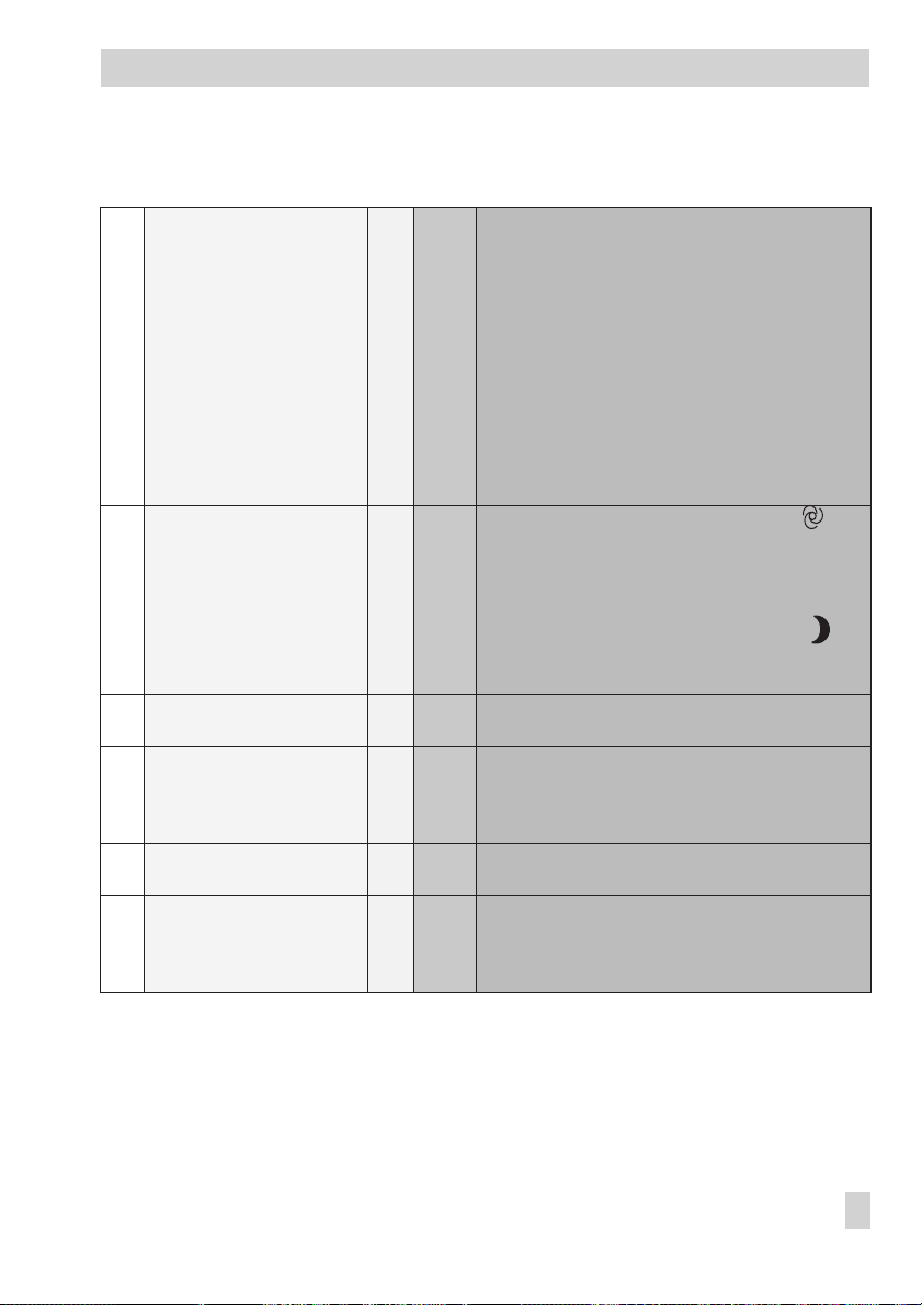
Appendix
Function
Fb
12 BA4 dependent on Y3 or
controlling the chiller
13 External request for
operation with BE1 and BE4
14
Fan operation feedback to
BE2
15 System frost protection with
BE3
16 Automatic switchover
between summer and winter
17 Selecting sensor type OFF 0 to 9 Fb17 = ON:Pt100 and Pt1000 sensors, mixed
WE Anl
OFF 1,
OFF 0 to 9 Fb13 = ON and operating mode switch at
OFF 0 to 9 Fb14 = ON:Function block parameters:
OFF 0 to 9 Fb 15 = ON: Standard operation or frost protection
ON 0 to 9 Fb16 = OFF: Automatic switchover between summer
Comment
Function block parameter/Range of values (default)
Fb12 = ON:
Select:
SEQ
4 to 9
PAr
Function block parameters with SEQ:
for 7
START
only
STOP
SEQ
Function block parameters with PA:
START MIN
3600 sec; (600 sec)
STOP MIN
3600 sec (600 sec)
STOP
(50 %)
BE1 = ON, BE4 = OFF: System ON; with start-up
mode, if needed
BE1 = BE4 = OFF: Operation acc. to times-of-use
BE4 = ON: System out of operation
Fb13 = ON and ooperating mode switch at :
BE1 = ON: Operation according to times-of-use
BE1 = OFF: System out of operation
START
dependent on BE3:
BE3 = OFF: Frost protection mode
BE3 = ON: Standard operation
time and winter time
possible
Fb17 = OFF: Pt100 and PTC sensors, mixed
possible
(operation in sequence) /
(operation in parallel)
(Activation value)/
(Deactivation value)/0 % up to
(Minimum activation time)/0, 60 to
(Minimim deactivation time) /0, 60 to
(Deactivate cooling when Y1 >)/0 to 100 %
(Delay time)/0 to 180 sec (180 sec)
STOP
up to 100 % (30 %)
START
(10 %)
EB 5477 EN 91
Page 92

Appendix
Function
Fb
18 Assigning the inputs AE1 to
AE4; 0 to 10 V
Note: Temperature
measured variables can only
be imposed on the analog
inputs as an alternative if
they are labeled in the
system diagrams. Locking
prevents an input being
assigned twice.
19 External demand for fan
speed 2
20 Request for externally
required signal
21 Operating action of Y1 OFF 0 to 6,
22 Operating action of Y2 OFF 2 to 9 Fb22 = ON: 0 to 100 % =10 to 0 V
23 Operating action of Y3 OFF 1,
WE Anl
OFF 0 to 9 Fb18 = ON:Determine measured variable and
OFF 0 to 9 Fb19 = ON: Only with Fb11 = ON;
OFF 0 to 9 Fb20 = ON:Externally required signal;
Comment
Function block parameter/Range of values (default)
measuring range for AE1 to AE4 ;
Select measured variable:
– –
(not assigned),
AE1F1
(supply air temperature F1),
AE3F2
(exhaust air temperature F2,
or
AE2F3
(outdoor temperature F3),
AE3F5
(room temperature F5),
AE2F6
(supply air humidity F6),
AE4F7
(exhaust air or room humidity F7),
or
AE4L
(air quality L)
Function block parameters: MIN to MAX
Temperatures for F1, F2, F3, F5:
MIN:
–40 to 0 °C (–40 °C)
MAX
Humidity for F6, F7
Air quality (0 to 10 V = 0 to 100 L):
Select:
from BE1
Function block parameters:
MIN AA
MAX AA (Flow requirement)/0 to 120 °C (90 °C)
MIN
MAX
Fb20 = OFF: Outdoor temperature, when available,
to AA: –40 to 50 °C = 0 to 10 V
Fb21 = ON: 0 to 100 % = 10 to 0 V
8, 9
Fb21 = OFF: 0 to 100 % = 0 to 10 V
Fb22 = OFF: 0 to 100 % = 0 to 10 V
Fb23 = ON: 0 to 100 % = 10 to 0 V
4 to 9
Fb23 = OFF: 0 to 100 % = 0 to 10 V
: 0 to 70 °C (50 °C)
:
MIN:
–10 to 10 % rH (0 % rH)
MAX:
90 to 110 % rH (100 % rH)
MIN:
–10 to 10 L (0 L)
MAX:
90 to 110 L (100 L)
BE4, BE7,
(Change when Y1)/0 to 100 °C (10 °C)
(Change when Y1)/0 to 100 °C (90 °C)
dependent on or independent
(Flow requirement)/0 to 120 °C (90 °C)
92 EB 5477 EN
Page 93

Appendix
Fb
Function
WE Anl
Comment
Function block parameter/Range of values (default)
24 Operating action of L OFF 0 to 9 Fb24 = ON: 0 to 100 L = 10 to 0 V
Fb24 = OFF: 0 to 100 L = 0 to 10 V
25 BE01 in FSR OFF 0 to 9 Fb25 = ON: Select:
StEIG
(entry in FSR for rising signal edge; make
contact)
FALL
(entry in FSR for negative signal edge; break
contact)
Note: Can only be changed with code number.
26 BE02 in FSR –> Fb 25
27 BE03 in FSR –> Fb 25
28 BE04 in FSR –> Fb 25
29 BE05 in FSR –> Fb 25
30 BE06 in FSR –> Fb 25
31 BE07 in FSR –> Fb 25
32 BE08 in FSR –> Fb 25
33 BE09 in FSR –> Fb 25
34 BE10 in FSR –> Fb 25
35 BE11 in FSR –> Fb 25
36 BE12 in FSR –> Fb25
37 Locking settings OFF 0 to 9 Fb37 = ON: CO level locked; PA level locked
except for time, date, set points, times-of-use, public
holidays and vacations
Note: Can only be changed with code number.
38 BA5 dependent on Y1 OFF 0 to 9 Fb38 = ON: BA5 ON/OFF dependent on Y1;
Function block parameters:
START
(Activation value)/STOP up to 100 % (30 %)
STOP
(Deactivation value)/0 up to START (10 %)
Lag time of the fans/0 to 60 sec (10 sec)
39 Variable air volume via
analog output AA
OFF 0 to 7 Fb39 = ON: Only with Fb20 = OFF; control of AA
dependent on analog input for air quality
Function block parameters:
MIN AA
K
* Only with cascade control
(Minimum air volume)/0 to 100 % (25 %),
(Factor of change)/0.0 to 10.0 (0.0)
P
EB 5477 EN 93
Page 94

Appendix
Function
Fb
40 Condensation detection OFF 1, 4,
WE Anl
Comment
Function block parameter/Range of values (default)
Fb40 = ON: Select: BE4, BE7
5, 6*,
StEIG
7, 8*,
9*
(entry in FSR for rising signal edge; make
contact)
FALL (entry in FSR for negative signal edge; break
contact)
Note: Can only be changed with code number.
41 Automatic reversal of the
operating action
42 Fan operation dependent on
room temperature/room
humidity
OFF 3, 5, 9 Fb41 = ON: Only with Fb2 = ON and Fb3 = ON
OFF 0 to 9 Fb42 = ON: Only with Fb11 = ON, with room
or AE3F2 and AE2F3
control or room cascade control and/or with
Fb7 (AE4F7); Select Reaction:
MIN
(When value falls below limit)
MAX (When value exceeds limit)
Function block parameters:
Difference in room temperature set point:
1 to 10 °C (5 °C) or
Difference in room humidity set point:
1 to 10 % rH (5 % rH)
43 Circulating air mode after
system start-up
44 Modem operation OFF 0 to 9 Fb44 = ON:Activated, function block parameters:
OFF 2, 4, 8 Fb43 = ON: Activated, not with supply air control
8 bit/16 bit addressing
In
(Cyclic initialization)/0 to 255 min (30 min)
PA
(Dialing interval when line is busy)/0 to 255
(5 min)
to (Time after missing Modbus query)/
(5 min)
PULS/ton
Control station phone number:
(0 to 9, P = Pause, - = End; maximum 23
characters)
(Dialing procedure) (PULS)
0 to 99 min
Note: Can only be changed with the code number.
45 Dialing when faults occur OFF 0 to 9 Fb45 = ON: Dialing initiated for incoming and
outgoing faults
Fb45 = OFF: Dialing initiated for incoming faults
Note: Can only be changed with the code number.
94 EB 5477 EN
Page 95

Appendix
Function
Fb
46 Alternative recipient OFF 0 to 9 Fb46 = ON: Alternative number;
WE Anl
Comment
Function block parameter/Range of values (default)
Function block parameters:
An
(Number of dialing attempts to control station)/
0 to 99 ( 5)
Alternative recipient’s telephone number/0 to 9, P =
Pause, - = End; maximum 23 characters)
Note: Can only be changed with the code number.
47 Prevent modem dialing OFF 0 to 9 Fb47 = ON: Modem does not dial control station
because of FSR change
Note: Can only be changed with the code number.
EB 5477 EN 95
Page 96

Appendix
12.2 List of parameters
Parameters in
PA level
The parameters displayed below are just examples. The system shown does not appear in
the controller.
Symbol Parameter description / Range of values (default setting)
0123456789101112131415161718192021222324
PA
M
Y2
M
Y2
0123456789101112131415161718192021222324
M M
Y1
M
Y3 Y2
PA
M
Y2
M
Y2
0123456789101112131415161718192021222324
M M
Y1
M
Y3 Y2
PA
M
Y2
M
Y2
0123456789101112131415161718192021222324
M M
Y1
M
Y3 Y2
PA
M
Y2
M
Y2
M M
Y1
M
Y3 Y2
Y1 Y2 Y3
Y1 Y2 Y3
Y1 Y2 Y3
Y1 Y2 Y3
Time
Supply air temperature set point
C
(0 to 50 °C; WE = 22 °C)
Exhaust air temperature set point
C
(0 to 40 °C; WE = 22 °C)
Room temperature set point
C
(0 to 40 °C; WE = 22 °C)
96 EB 5477 EN
Page 97

Symbol Parameter description / Range of values (default setting)
0123456789101112131415161718192021222324
MIN
PA
M
Y2
M
Y2
0123456789101112131415161718192021222324
MAX
M M
Y1
M
Y3 Y2
PA
M
Y2
M
Y2
0123456789101112131415161718192021222324
KTT
p
NV
PA
M
Y2
M
Y2
0123456789101112131415161718192021222324
M M
Y1
M
Y3 Y2
M M
Y1
M
Y3 Y2
PA
M
Y2
M
Y2
0123456789101112131415161718192021222324
M M
Y1
M
Y3 Y2
Y1 Y2 Y3
Y1 Y2 Y3
Y1 Y2 Y3
Y1 Y2 Y3
Supply air temperature minimum limit
C
(0 °C to [Supply air temperature maximum limit];
WE = 18 °C)
Supply air temperature maximum limit
C
([Supply air temperature minimum limit] to 50 °C;
WE = 26 °C)
Heating coil (0.1 to 99.9; WE = 0,5)
K
P
Heating coil (1 to 999 sec; WE = 60 sec)
T
N
Heating coil (– – – to 999 sec; WE = – – –)
T
V
Temperature set point of the slave loop
C
(0 to 50 °C; WE = 22 °C)
K
Temperature master loop
P
Appendix
K
p
PA
M
Y2
M
Y2
M M
Y1
M
Y3 Y2
Y1 Y2 Y3
(0.1 to 99.9 sec; WE = 1.0)
EB 5477 EN 97
Page 98

Appendix
Symbol Parameter description / Range of values (default setting)
KPTemperature master loop
(0.1 to 99.9; WE = 1.0)
Return air temperature minimum limit
(0 °C to [Return air temperature maximum limit];
WE = 20 °C)
Return air temperature maximum limit (coordinate 1, 2 recognizable from the square located to the right of 1, 2)
([Return air temperature minimum limit] to 100 °C;
WE = 70 °C)
0123456789101112131415161718192021222324
PA
M
Y2
M
Y2
0123456789101112131415161718192021222324
PA
M
Y2
M
Y2
M M
Y1
M
Y3 Y2
M M
Y1
M
Y3 Y2
98 EB 5477 EN
Outdoor temperature, coordinate 1
C
(–50 to 20 °C; WE = 5 °C)
Y1 Y2 Y3
Outdoor temperature, coordinate 2
C
(–50 to 20 °C; WE = 20 °C)
Y1 Y2 Y3
Page 99

Symbol Parameter description / Range of values (default setting)
0123456789101112131415161718192021222324
Return air temperature limit factor
Appendix
K
p
PA
M
Y2
M
Y2
0123456789101112131415161718192021222324
START
M M
Y1
M
Y3 Y2
PA
M
Y2
M
Y2
0123456789101112131415161718192021222324
START
M M
Y1
Y3 Y2
M
PA
M
Y2
M
Y2
0123456789101112131415161718192021222324
START
M M
Y1
Y3 Y2
M
PA
M
Y2
M
Y2
0123456789101112131415161718192021222324
STOP
MAX
M M
Y1
Y3 Y2
M
PA
M
Y2
M
Y2
M M
Y1
Y3 Y2
M
Y1 Y2 Y3
Y1 Y2 Y3
Y1 Y2 Y3
Y1 Y2 Y3
Y1 Y2 Y3
(0 to 10; WE = 1)
Sustained room temperature
C
(0 to 20 °C; WE = 15 °C)
Start-up mode when the outdoor temperature is smaller
C
(0 to 10 °C; WE = 5 °C)
Pump advance running time for start-up
sec
(0, 60, 120 to 900 sec; WE = 300 sec)
Control signal limit for Y1
%
(0 to 100 %; WE = 100 %)
EB 5477 EN 99
Page 100

Appendix
Symbol Parameter description / Range of values (default setting)
0123456789101112131415161718192021222324
START
PA
M
Y2
M
Y2
0123456789101112131415161718192021222324
M M
Y1
Y3 Y2
M
PA
M
Y2
M
Y2
0123456789101112131415161718192021222324
M M
Y1
Y3 Y2
M
Y1 Y2 Y3
Y1 Y2 Y3
Pump ON when the outdoor temperature is smaller
C
(–50 to 10 °C; WE = 0 °C)
Summer compensation when outdoor temperature is grea
C
ter
(–50 to 40 °C; WE = 26 °C)
Set point at an outdoor temperature of 32 °C;
C
Supply air temperature
-
PA
M
Y2
32C
M
Y2
0123456789101112131415161718192021222324
M M
Y1
Y3 Y2
M
PA
M
Y2
32C
M
Y2
0123456789101112131415161718192021222324
M M
Y1
Y3 Y2
M
PA
M
Y2
32C
M
Y2
M M
Y1
Y3 Y2
M
100 EB 5477 EN
Y1 Y2 Y3
Y1 Y2 Y3
Y1 Y2 Y3
(0 to 40 °C; WE = 26 °C)
Set point at an outdoor temperature of 32 °C;
C
Exhaust air temperature
(0 to 40 °C; WE = 26 °C)
Set point at an outdoor temperature of 32 °C;
C
Room temperature
(0 to 40 °C; WE = 26 °C)
 Loading...