

Page 1
Automation System TROVIS 5400
Heating and District Heating Controller
TROVIS 5475-2
®
Electronics from SAMSON
Fig. 1 ⋅ TROVIS 5475-2
Edition January 2001
Firmware Version
1.10
Mounting and operating instructions
EB 5475-2 EN
Page 2

Contents
. . . . . . . . . . . . . . . . . . . . . . . . . . . . . . . . . . . . . Page
1. General
. . . . . . . . . . . . . . . . . . . . . . . . . . . . . . . . . . . . 4
1.1 Notes for the user . . . . . . . . . . . . . . . . . . . . . . . . . . . . . . . . 4
1.2 Technical data . . . . . . . . . . . . . . . . . . . . . . . . . . . . . . . . . 5
1.3 Sensor resistance values . . . . . . . . . . . . . . . . . . . . . . . . . . . . 6
2. Installation
. . . . . . . . . . . . . . . . . . . . . . . . . . . . . . . . . . 7
2.1 Installing the controller . . . . . . . . . . . . . . . . . . . . . . . . . . . . . 7
2.2 Installing the sensors . . . . . . . . . . . . . . . . . . . . . . . . . . . . . . 8
3. Electrical connections
. . . . . . . . . . . . . . . . . . . . . . . . . . . . . 8
3.1 General . . . . . . . . . . . . . . . . . . . . . . . . . . . . . . . . . . . . 8
3.2 Connecting the controller . . . . . . . . . . . . . . . . . . . . . . . . . . . . 9
3.3 Connecting the sensors . . . . . . . . . . . . . . . . . . . . . . . . . . . . . 9
3.4 Terminal wiring diagrams . . . . . . . . . . . . . . . . . . . . . . . . . . . . 9
4. Description of the controller functions
. . . . . . . . . . . . . . . . . . . . . . 13
4.1 Optimize . . . . . . . . . . . . . . . . . . . . . . . . . . . . . . . . . . . 13
4.2 Adaptation . . . . . . . . . . . . . . . . . . . . . . . . . . . . . . . . . . 13
4.3 Reduced operation . . . . . . . . . . . . . . . . . . . . . . . . . . . . . . . 14
4.4 Summer time operation . . . . . . . . . . . . . . . . . . . . . . . . . . . . . 14
4.5 Automatic clock reset summer time/winter time . . . . . . . . . . . . . . . . . . 15
4.6 Public holidays and vacations . . . . . . . . . . . . . . . . . . . . . . . . . . 15
4.7 Delayed outdoor temperature adaptation . . . . . . . . . . . . . . . . . . . . 15
4.8 Limitation of the return flow temperature . . . . . . . . . . . . . . . . . . . . . 16
4.9 Limitation of the system deviation for OPEN signal . . . . . . . . . . . . . . . . 17
4.10 Forced charging of the drinking water storage tank . . . . . . . . . . . . . . . . 17
4.11 Thermal disinfection of the drinking water storage tank . . . . . . . . . . . . . . 17
4.12 Frost protection . . . . . . . . . . . . . . . . . . . . . . . . . . . . . . . . . 17
4.13 Defective sensors . . . . . . . . . . . . . . . . . . . . . . . . . . . . . . . . 18
4.14 Forced operation of the pumps . . . . . . . . . . . . . . . . . . . . . . . . . 18
4.15 Limitation of flow rate or capacity . . . . . . . . . . . . . . . . . . . . . . . . 19
5. System descriptions and diagrams
5.1 System code number 1.0 . . . . . . . . . . . . . . . . . . . . . . . . . . . . 20
5.2 System code number 2.0 . . . . . . . . . . . . . . . . . . . . . . . . . . . . 21
System code number 2 .0 with changeover valve . . . . . . . . . . . . . . . . . 21
System code number 2.1 . . . . . . . . . . . . . . . . . . . . . . . . . . . . 23
5.3 System code number 3.0 . . . . . . . . . . . . . . . . . . . . . . . . . . . . 24
5.4 System code number 4.0 . . . . . . . . . . . . . . . . . . . . . . . . . . . . 26
System code number 4 .1 . . . . . . . . . . . . . . . . . . . . . . . . . . . . 27
System code number 4.2 . . . . . . . . . . . . . . . . . . . . . . . . . . . . 28
5.5 System code number 5.0 . . . . . . . . . . . . . . . . . . . . . . . . . . . . 29
5.6 System code number 6.0 . . . . . . . . . . . . . . . . . . . . . . . . . . . . 30
2
. . . . . . . . . . . . . . . . . . . . . . . 20
Page 3
6. Operation
6.1 Operating controls . . . . . . . . . . . . . . . . . . . . . . . . . . . . . . 32
6.2 Selecting the operating modes . . . . . . . . . . . . . . . . . . . . . . . . . 32
6.2.1 Remote controlling the heating system . . . . . . . . . . . . . . . . . . . . . 33
6.3 Control levels . . . . . . . . . . . . . . . . . . . . . . . . . . . . . . . . . 34
6.3.1 Configuration level . . . . . . . . . . . . . . . . . . . . . . . . . . . . . . 34
6.3.2 Parameter level . . . . . . . . . . . . . . . . . . . . . . . . . . . . . . . . 34
6.3.3 Operating level . . . . . . . . . . . . . . . . . . . . . . . . . . . . . . . . 34
Increasing/decreasing the room temperature
. . . . . . . . . . . . . . . . . . . . . . . . . . . . . . . . . . 32
. . . . . . . . . . . . . . . . . 37
7. Starting up and configuring the controller
7.1 Configuration . . . . . . . . . . . . . . . . . . . . . . . . . . . . . . . . 38
7.1.1 Setting the code number . . . . . . . . . . . . . . . . . . . . . . . . . . . 38
7.1.2 Setting the system code number (Anl) . . . . . . . . . . . . . . . . . . . . . 39
7.1.3 Setting the function blocks . . . . . . . . . . . . . . . . . . . . . . . . . . . 39
7.1.4 Function block list . . . . . . . . . . . . . . . . . . . . . . . . . . . . . . . 42
7.1.4 Sensor calibration . . . . . . . . . . . . . . . . . . . . . . . . . . . . . . 46
7.2 Parameterization . . . . . . . . . . . . . . . . . . . . . . . . . . . . . . . 47
7.2.1 Resetting to default values . . . . . . . . . . . . . . . . . . . . . . . . . . . 47
7.2.2 Entering and modifying user data . . . . . . . . . . . . . . . . . . . . . . . 48
Entering current time and date . . . . . . . . . . . . . . . . . . . . . . . . . 48
Entering parameters for heating circuit:
Heating characteristics and temperatures . . . . . . . . . . . . . . . . . . . 48
Time schedule for heating . . . . . . . . . . . . . . . . . . . . . . . . . . . 51
Public holidays . . . . . . . . . . . . . . . . . . . . . . . . . . . . . . . . 53
Vacations . . . . . . . . . . . . . . . . . . . . . . . . . . . . . . . . . . 53
Entering parameters for drinking water circuit:
Temperatures . . . . . . . . . . . . . . . . . . . . . . . . . . . . . . . . . 54
Time schedule for drinking water heating . . . . . . . . . . . . . . . . . . . . 56
Time schedule for circulation pump . . . . . . . . . . . . . . . . . . . . . . 56
7.3 Personal code numbers, locking the mode switch for manual operation and
enabling the write protect function for the configuration level . . . . . . . . . . 57
7.4 Configuring the correction switch . . . . . . . . . . . . . . . . . . . . . . . 58
. . . . . . . . . . . . . . . . . . . 38
8. Data transfer using memory module
9. Configured data
Assembly, start-up and operation of the device may only be performed
by trained and experienced personnel familiar with this product. Proper
!
shipping and appropriate storage are assumed.
The controller is designed for use in power installations. For connection
and maintenance you are required to observe the relevant safety regulations.
. . . . . . . . . . . . . . . . . . . . . 59
. . . . . . . . . . . . . . . . . . . . . . . . . . . . . . . 60
3
Page 4

1. General
The heating and district heating controller is designed for weather-compensated flow temperature control. This means it controls the flow temperature of a heating system based on a heating
characteristic so that the room temperature is always maintained at the desired level regardless
of the outdoor temperature. When used as a district heating controller, the controller can limit
the return flow temperature variably according to the outdoor temperature.
A drinking water heating system may be operated from the primar y heating circuit, using a second control loop, or from the secondary heating circuit.
A differential temperature control featuring a meter tracking the operating hours of the solar
circuit pump is included in three system configurations for the solar heating of drinking water
storage tanks.
The connected sensors allow the controller to measure the respective temperatures which are
transmitted to the central signal processing system. Subsequently, this system issues a three-step
or on/off control signal corresponding to the preset set points for each of the two control loops.
In addition, the controller controls the heating circulation pump and the pumps for drinking
water heating. The signal from a heat meter that is proportional to the flow rate or capacity can
be connected to a pulse or current input. This enables the limitation of a maximum and/or minimum flow rate or capacity.
These mounting and operating instructions are valid for:
Firmware version 1.0 upwards
(The firmware version installed appears for 2 seconds in the display when the controller is
switched on)
Whats new compared to the previous version?
The circulation pump ZP runs on a time schedule in all systems.
1.1 Notes for the user
The installation of the controller and its electrical connection described in the following and,
must be carried out by authorized personnel only.
The settings for configurations described in chapter 7.1 also require specialized knowledge of
heating systems and should only be performed by an expert. This also applies for the description of the controller functions and system configurations described in chapter 4 and 5.
The start-up of the controller is normally carried out by authorized personnel all configuration
data should be entered into the configured data tables in chapter 9.
The controller is programmed with default temperature values and time schedules that can be
changed on start-up or by the user at a later date over the menu described in chapter 7.2.2.
The settings for the end user
and non-expert should be restricted to changing the heatings flow
temperature to increase or decrease room temperatures (chapter 6.3.3 on page 37) and
changing the set times-of-use (chapter 7.2.2 on page 51).
The current time and date are saved in memory for at least 24 hours when the controller is
left unconnected to the power supply. Other configuration data are stored in memory indefinitely and cannot be lost.
4
Page 5
1.1 Technical data
Inputs
Sensor inputs Max. 7 PTC and Pt 100 or NTC and Pt 100, or Pt 1000 and Pt
100 sensors
2-wire circuit
(heating circuit/drinking water circuit)
2 flow temperature sensors, alternatively 1 solar collector sensor
1 room temperature sensor
1 outdoor temperature sensor
1)
1 return flow temperature sensor ( 2 in system code no. 4)
2 storage tank temperature sensors
Binary inputs Storage tank thermostat
Additional inputs Current input 4(0)...20 mA for flow rate limitation or pulse
counting input for limitation of capacity or flow rate
Current input 4(0)...20 mA for outdoor temperature
Remote control option for correcting flow temperature and
selecting the operating mode
Outputs
Control signal y Three-step signals: max. load 250 V AC, 2 A;
min. 10 mA, varistor suppression 300 V
On/off signal: max. load 250 V AC, 2 A;
min. 10 mA, varistor suppression 300 V
Binary outputs Max. 4 outputs for pump control
Load: max. 250 V AC, 2 A min. 10 mA, varistor
suppression 300 V
Control parameters K
= 0.1...50; Tn = 1...999 s; valve transit time Ty = 15...240 s
p
Operating voltage 230 V AC (+10 %/15 %), 48 to 62 Hz,
Power failure: All parameter and configuration data are saved
in an EEPROM.
Power consumption Approx. 1.5 VA
Temperature range Operation: 0...40 Storage: 20 to 60 °C
1)
Degree and class of protection IP 40 according to IEC 529 and II according to VDE 0106
Degree of contamination 2 according to VDE 0110
Overvoltage category II according to VDE 0110
Humidity rating F according to VDE 40040
Noise immunity Corresponding to EN 50082 Part 1
Noise emission Corresponding to EN 50081 Part 1
Weight approx. 0.5 kg
1)
On using Pt100 or Pt100 resistance thermometers, permissible temperature
range down to −65 °C, however, display only indicates down to −40 °C
5
Page 6

CAUTION
Safety features such as frost protection monitoring and excess temperature protection are not
active in the following cases:
Defective heating controller and failure of its functions
•
Sensors are faulty, not connected or have not been deactivated
•
No power supply to the controller
•
Mode switch set to manual operation
•
1.2 Sensor resistance values
Resistance thermometer with PTC measuring element
Sensors for outdoor temperature Type 5224, for flow and return flow temperature Types 5264
and 5265, for storage tank temperature Type 5264, sensor for room temperature with remote
control Type 5244
°C 20 10 0 +10 +20 +25 +30 +40 +50 +60 +70 +80 +90 +100 +110 +120
Ohm 694 757 825 896 971 1010 1050 1132 1219 1309 1402 1500 1601 1706 1815 1925
Room temperature
sensor with remote
control Type 5244
Switch position "clock", terminals 1 and 2 °C +10 +15 +20 +25 +30
Ohm 679 699 720 741 762
Resistance thermometer with Pt 100 measuring element
Sensors for outdoor temperature Type 5225, for flow and return flow temperature Types 5204
and 5205-47, for storage tank temperature Types 5205-46 and 5205-48, sensor for room temperature Type 5255
°C -35 -30 -25 -20 -15 -10 -5 0 5 10
Ohm 86.25 88.22 90.19 92.16 94.12 96.09 98.04 100.00 101.95 103.90
°C15202530354045505560
Ohm 105.85 107.79 109.73 111.67 113.61 115.54 117.47 119.40 121.32 123.24
°C 65 70 75 80 85 90 95 100 105 110
Ohm 125.16 127.07 128.98 130.89 132.80 134.70 136.60 138.50 140.39 142.29
°C 115 120 125 130 135 140 145 150
Ohm 144.17 146.06 147.94 149.82 151.70 153.58 155.45 157.31
Resistance values with Pt1000 measuring element
Use the resistance values in the table for the Pt100 and multiply the values by the factor of 10.
Sensor for outdoor temperature Type 5227, for flow and return flow temperature Types 5207-
21, 5207-27, 5277 (thermowells required) and Type 5267 (surface sensor),
for storage tank temperature Type 5207-46 and Type 5207-48,
sensor for room temperature Type 5257-1,
room temperature sensor with remote control Type 5257-4.
6
Page 7
2. Installation
2.1 Installing the controller
The controller is made up of the controller casing which contains the electronics components
and the rear casing section with the terminal blocks. To connect the controller, remove the screws
on the front panel and separate the controller housing from the rear casing.
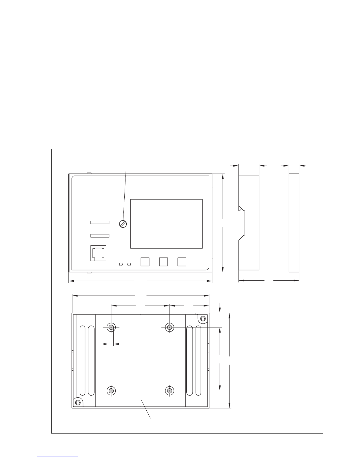
For wall mounting, use four screws to mount the rear casing to a wall. The distances between the
holes are shown in Fig. 2.
For top hat rail mounting, mount the controller onto the top hat rail using the spring-mounted
hook on the rear casing.
For panel mounting, push the controller casing through the panel cut-out (92 x 138 mm) and insert the fastening clips (delivered with the controller) into the notches at the top and bottom of
the casing. Then turn the threaded bolts in the direction of the control panel so that the casing is
pressed with its front frame against the control panel.
Fixing screw on controller section
30 10
98
144 59
138
57 41
15
Ø 4.5
62
93
Panel cut-out
92 x 138 mm
Fig. 2 ⋅ Dimensional diagram
Fastening section on controller rear casing
7
Page 8

2.2 Installing the sensors
2.2.1 Outdoor sensor
Use two screws to mount the outdoor sensor to the outside wall at an appropriate place. Make
sure that the sensor is mounted away from direct heat sources (windows, vents etc.). In case of
single family dwellings, preferably mount the sensor on the wall at the side of the house where
the most frequently occupied rooms are situated.
2.2.2 Flow/return flow sensor
Mount the sensor as duct sensor or surface sensor in an easily accessible location near the control valve:
Duct sensor:
Surface sensor:
polish the pipe clean. Firmly press the sensor onto the pipe and secure it to the pipe using the enclosed tightening strap.
2.2.3 Room sensor
Mount the sensor on the wall approx. 150 cm above the floor at an appropriate place. Make
sure that the air circulation is not obstructed by cupboards, curtains or similar items.
3. Electrical connections
3.1 General
!
Use separate cables for 230 V supply line and the signal lines!
•
Also use separate cables for the digital signal lines (bus lines) and the analog signal lines
•
(sensor lines).
Insert the duct sensor into a thermowell as far as it will go.
Remove insulation from the flow pipe where the sensor is to be mounted and
CAUTION!
For wiring and connection of the controller, you are required to observe the VDE
regulations and the regulations of the local power supply company. For this reason,
this type of work must be carri ed out b y a spec ia list.
In systems with a high electromagnetic noise level, we recommend that shielded cables be
•
used for the analog signal lines.
Ground the shield at the inlet or outlet of the control cabinet, using the largest possible cross
section and via the shortest possible route.
The central grounding point must be connected to the grounding conductor using a min.
10 mm
As a rule, the shield needs only be grounded on one side at the control cabinet inlet, except
when an equipotential bonding exists that has much lower resistance than the shield resistance.
To increase the noise immunity, make sure that there is a minimum distance of 10 cm be-
•
tween the power cables and signal lines. We recommend that this distance between these
lines is also kept in the control cabinet!
Inductances in the control cabinet, e.g. contactor coils, must be equipped with suitable inter-
•
ference suppressors (RC elements)!
Control cabinet elements with a high field strength, e.g. transformers or frequency converters, should be shielded by means of separators that have good chassis ground.
8
2
cable.
Page 9
Surge protection
The following measures must be taken if lines are installed outside of the building or over long
distances:
The shield of signal lines routed outside of buildings must have current carrying capacity
•
and must be grounded on both sides.
Surge diverters must be installed at the control cabinet inlet.
•
3.2 Connecting the controller
Connect the controller on the basis of the relevant terminal diagrams of the associated system
code numbers (Fig. 3 to 10).
The power supply section of the controller terminals 14 to 26 must be connected using wires
with a cross-section of 1.5 mm
2
at the minimum.
Knock out the holes marked on the rear casing for the cable entries and insert the enclosed selfsealed grommets or suitable glands.
3.3 Connecting the sensors
Connect the cables with a cross-section of min. 0.5 mm
2
to the terminal strip terminals 1
to 13 on the rear casing. See chapter 7.1.4 for Pt100 (Pt1000/PTC) on sensor calibration.
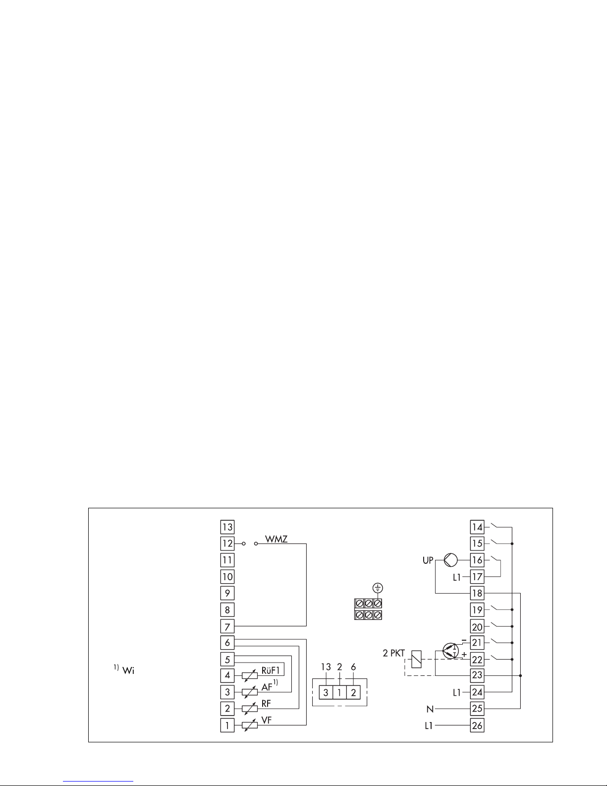
3.4 Terminal wiring diagrams
Legend for circuit diagrams:
AF Outdoor sensor SLP Storage tank charging pump
RF Room sensor UP Circulation pump of heating circuit
RÜF Return flow sensor ZP Circulation pump of drinking water circuit
SF Storage tank sensor WMZ Heat meter
VF Flow sensor Solar circuit:
TW Drinking water circuit CF Solar circuit collector sensor
HK Heating circuit CP Solar circuit pump
2 PKT On/off
With 0 …20 mA
50 Ω connect in parallel
Fig. 3
System code no. 1
Option Type 5244
Type 5257-4
9
Page 10
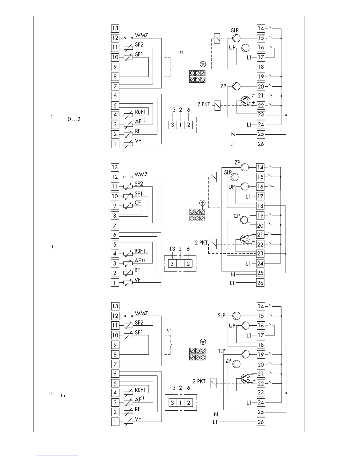
Thermostat
Changeover
valve
With 0 …20 mA
50 Ω connect in parallel
Fig. 4
System code no. 2.0
With 0 …20 mA
50 Ω connect in parallel
Fig. 5
System code no. 2.1
Option Type 5244
Type 5257-4
Stage1
Stage 2
Option Type 5244
Type 5257-4
Wit h 0 …20 mA
50 Ω connect in parallel
Fig. 6
System code no. 3.0
10
Thermostat
Option Type 5244
Type 5257-4
Page 11
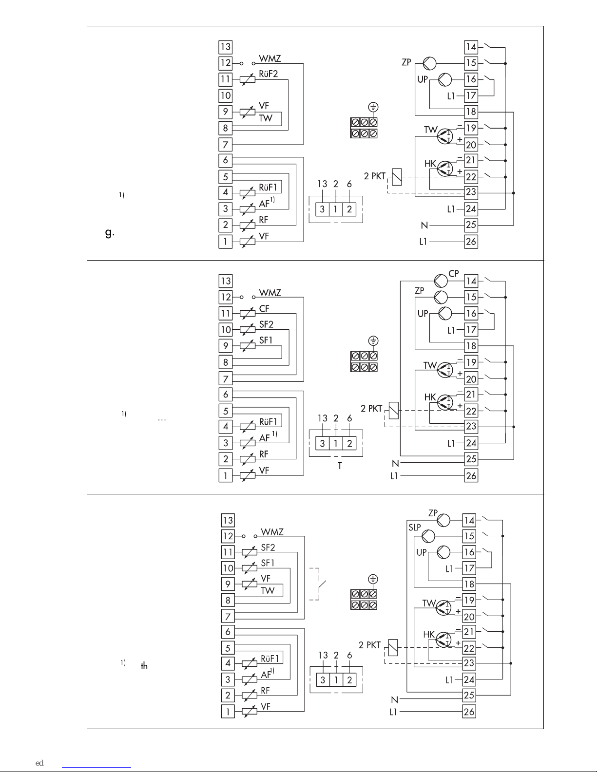
Wit h 0 …20 mA
50 Ω connect in parallel
Fig. 7
System code no. 4.0
Wit h 0 …20 mA
50 Ω connect in parallel
Fig. 8
System code nos. 4.1,
4.2
Option Type 5244
Type 5257-4
Option Type 5244
Type 5257-4
Wit h 0 …20 mA
50 Ω connect in parallel
Fig. 9
System code no. 5.0
Thermostat
Option Type 5244
Type 5257-4
11
Page 12

* Fast-reacting
sensor/actuator
With 0 …20 mA
50 Ω connect in parallel
Fig. 10
System code no. 6.0
Option Type 5244
Type 5257-4
12
Page 13

4. Description of the controller functions
The following function descriptions are intended to help you understand the settings required for
operation.
The controller functions depend on the selected system code numbers (1 to 6). See chapter 5 for
details.
4.1 Optimize
The controller is capable of automatically determining the most favorable times for activation/deactivation of the heating system in periodically occupied buildings. To activate this function, select function block setting FB 0 = ON (linked to FB 13 = ON).
In contrast to the reduced operation, the heating system is deactivated at the latest when the
time of non-use starts. A reference room with an installed room temperature sensor is monitored in place of the entire building. Whenever the room temperature falls below an adjustable
Sustained temperature, the controller activates the heating until the temperature exceeds the
sustained temperature (plus approx. 0.5°C differential gap) again. To achieve this, the system
can be run at the maximum permissible flow temperature.
The controller determines when the heating should be activated to start rated operation of the
system so that the Room temperature set point (temperature adjustable at the controller) is just
reached when the set time-of-use begins. The heating may be activated up to 6 hours before the
set time-of-use begins (this is the case on start-up as the controller has not yet stored any information concerning the building characteristics).
Drinking water is not heated in system code numbers 2 and 3 during the preheating time. The
controller determines when the heating is to be deactivated so that the temperature does not fall
significantly below the desired room temperature towards the end of time-of-use due to the
heating being deactivated before the time-of-use ends (e.g. direct sunlight can cause an increase in room temperature, especially if the flash adaptation is not used, and this in turn leads
to the system being deactivated too soon). The heating may be deactivated up to 2 hours before
the set time-of-use ends.
If 2 rated operation times are set for one day, the controller does not monitor the Sustained temperature, but a Reduced room temperature set point (the temperature adjustable at the controller) between both time blocks.
4.2 Adaptation
The controller is capable of automatically adapting the heating characteristic to the building
characteristics. Based on the default heating characteristic (gradient value 1.8), a reference
room with an installed room temperature sensor is monitored in place of the entire building. If
the measured room temperature deviates from the adjustable Room temperature set point on
the average during the time-of-use when the mode switch is set to , the subsequent rated
operation time is based on the altered heating characteristic gradient, provided the function
block setting is set to FB 1 = ON. The corrected value is displayed in the parameter level as
Gradient of the heating; this parameter cannot be accessed to change it manually when the
adaptation mode (FB = 1) is selected.
Immediate responses to deviations in room temperature can be achieved using the function
block setting FB 2 = ON: the flash adaptation compensates for deviations in room temperature
during time-of-use when the mode switch is set to , by lowering or raising the heating characteristic by up to 30 °C (parallel displacement of the heating characteristic). Combined with
adaptation mode (FB 1 = ON), a maximum displacement of 5 °C is designated.
13
Page 14

The displacement is displayed as Level of the heating characteristic; this parameter cannot be
accessed to adjust it manually when the flash adaptation mode (FB 2 = ON) is selected.
The options on the controller and remote control to correct the set point apply to the room temperature set point in adaptation/flash adaptation mode.
4.3 Reduced operation
In reduced operation, the heating circuit generally operates on a flow temperature set point
value defined by the heating characteristic and reduced by the value set under Set-back of flow
temperature for reduced operation. If, however, during times of non-use, the outdoor temperature exceeds the value entered as the Outdoor temperature limit value for deactivation in reduced operation, the controller automatically deactivates the heating system by closing the
control valve, and the heating circulation pump UP is deactivated after the set lag time has
elapsed. If the outdoor temperature falls below the limit value (approx. 0.5 °C differential
gap), the heating system immediately starts operating again.
If the outdoor temperature falls below the Outdoor temperature limit value for reactivation of
rated operation in reduced operation during times of non-use, the value set under Set-back of
flow temperature for reduced operation is ignored: the flow set point for rated operation is
used.
4.4 Summer time operation
In summer time operation, the controller automatically deactivates the heating system, by closing the control valve and the heating circulation pump UP is switched off after the set lag time
has elapsed.
The outdoor temperature is the decisive factor for the start of summer time operation. If it exceeds the parameter Outdoor temperature limit value for summer time operation (default setting: 22 °C; setting range: 0...50 °C), summer time operation is directly activated.
When this limit value (approx. 0.5 °C differential gap) is not reached, the heating immediately
starts operating again.
The Time-controlled summer time operation function is linked to the setting the function block
FB 3 = ON and only activated when the mode switch is set to .
The decisive factors for time-controlled summer time operation to become active are:
The current date. If it lies within the effective time period of summer time operation
(settings in the configuration level linked to the function block setting FB 3 = ON. Default:
01.06. to 30.09.)
The daytime mean temperature (measured between 7:00 and 22:00 hrs) exceeds the out-
door temperature limit value on the corresponding number of subsequent days
(settings in the configuration level linked to the function block setting FB 3 = ON. Default:
outdoor temperature limit value 18 °C setting range 0 to 30 °C and 2 days to activate
the time-controlled summer time operation setting range 1...3)
14
Page 15

If the time-controlled summer time operation is active, heating operation will not start even at
lower outdoor temperatures when the t ime- of-u se st ar ts.
The time-controlled summer time operation is only deactivated when the daytime mean temperature falls below the outdoor temperature limit value on the corresponding number of subsequent days.
(Setting in the configuration level linked to the function block setting FB 3 = ON. Default: 1 day
to deactivate the time-controlled summer time operation setting range 1...3)
If the heating system is also deactivated due to the parameters Outdoor temperature limit value
for summer time operation and the Time-controlled summer time operation, the heating is not
reactivated when the temperature falls by approx. 0.5 °C below the values in the above mentioned parameters.
Info display about the time-controlled summer time operation.
If the display of the outdoor temperature is selected (function block FB 3 = ON) in the operating
level when the summer time operation is activated and the key is held down, the daytime
mean temperature is displayed.
The bars at the top of the display show the temperature curve over the past 8 days. The black
areas show where the temperature exceeded the limit value and the empty areas where the temperature fell below the limit value. A black area marked 1, for example, means that the outdoor
temperature limit was exceeded on average on the previous day.
4.5 Automatic clock reset summer time/winter time
When you set the function block FB 5 = ON, the controller automatically resets the clock on the
last Sunday in March from 2:00 to 3:00 hrs and on the last Sunday in October from 3:00 to
2:00 hrs.
4.6 Public holidays and vacations
The controller lets you define 20 public holidays and 10 vacation periods (parameter level).
There is no default setting for public holidays.
On public holidays, the heating system operates based on the data entered for Sundays (heating time schedule); during vacations, the heating runs in reduced or standby operation.
The drinking water heating is not affected by public holidays and vacations when the controller
operates using default settings. When you activate the function block FB 6 = ON, the drinking
water heating will then operate on public holidays using the same time schedule entered for
Sundays (time schedule for drinking water heating). Subsequently, the drinking water heating is
then not active during vacations (frost protection monitoring from +5 °C downwards).
4.7 Delayed outdoor temperature adaptation
This function is used to determine the flow temperature set point using a calculated outdoor temperature which is delayed either:
a) only when the outdoor temperature decreases, or
b) regardless of the outdoor temperature.
For instance, if the outdoor temperature varies by 12 °C within a very short time , the Calcu-
lated outdoor temperature is adapted to the outdoor temperature in small steps over a time
period of 4 hours with a delay setting of 3 °C/hr. This function helps to prevent heating system
overloads in combination with overheated buildings, or temporarily insufficient heating due to
short-term outdoor temperature variations, e.g. caused by warm winds or excessive solar radi-
15
Page 16

ation on the outdoor temperature sensors.
An active delayed outdoor temperature adaptation is signalized in the operating level by a
blinking outdoor temperature in the display. When you keep key pressed down, the Calculated outdoor temperature is shown in the display.
If the function Time-controlled summer time operation (FB 3 = ON) is activated, the calculated
outdoor temperature is not indicated in the display.
4.8 Limitation of the return flow temperature
For an economical operation of a district heating system, it is required that as much heat as
possible be extracted from the heat transfer medium (water) circulating through the system. The
difference in temperature between the flow and return flow in the network is used to indicate
how much energy is being consumed: a large difference in temperature indicates a high level of
energy efficiency and a small difference indicates a low level of energy efficiency. One return
flow temperature sensor is sufficient to evaluate the difference in temperature when the flow
temperature in the network is predetermined.
The function is as follows: the return flow temperature can either be limited depending on the
outdoor temperature (variable) or by a fixed value. If the return flow temperature measured at
the return flow sensor RüF1 exceeds the limit value calculated from the set return flow characteristic or the fixed limitation value by the value x, the respective calculated or fixed set point
(flow temperature of heating, charging temperature) is reduced by the value x, multiplied by return flow temperature limitation factor. As a result, the primary flow rate is reduced with the effect that the return flow temperature drops. Both the measured value of the Return flow temperature and the set point (flow temperature of heating, charging temperature) blink in the display when a limitation case occurs. The function is already activated by the function block setting FB 20 = ON.
In system code numbers 2 and 3 (drinking water heating implemented in the secondary circuit),
the controller switches during the heating up of drinking water over to the parameter Return
flow limitation temperature during drinking water heating from the return flow temperature
limitation value (calculated from the return flow temperature limitation characteristic). This ensures that the return flow limitation temperature in the heating circuit can be held low in the seasonal interim period.
In system code number 4, a separate return flow temperature limitation in the drinking water
circuit is additionally possible, provided FB 21 = ON.
System code number 5 allows you to include the return flow temperature of the drinking water
circuit. For this purpose, the return flow temperature sensor must be mounted in a return flow
pipe used in both circuits, and the function block FB 21 must be activated (ON). When FB 21 is
activated (ON), the parameter Return flow limitation temperature during drinking water heating (the temperature is adjustable at the controller) is activated. When drinking water is being
heated, the highest value from both return flow temperature limitation values (heating circuit
and drinking water circuit) is used for the limitation control. When a limitation occurs, both the
set point in the heating circuit and the set point in the drinking water circuit are reduced. If the
priority for drinking water through set-back operation is additionally activated (FB 8 = ON, setting "Ab"), the reduced heating circuit set point is also further reduced when a limitation occurs!
In system code number 6, a return flow temperature limitation is only possible in the heating circuit.
16
Page 17

4.9 Limitation of the system deviation for OPEN signal
When using the controller for steam pressure control, we recommend that you activate this function. It limits the controllers reaction to set point deviations which cause the control valve to
open. This makes it much easier to start up such systems without complications. The controllers
response to set point deviations which cause the control valve to close are not affected by this
function.
In the system code numbers 1, 2 and 3, the function must be activated via FB 11 = ON.
In the system code numbers 4, 5 and 6 set
FB 11 = ON to activate the function linked to the heating circuit, and
FB 12 = ON to activate the function linked to the drinking water circuit.
4.10 Forced charging of drinking water storage tank
Systems 2, 3 and 5 are equipped with this function as standard, provided that a storage tank
sensor (not a storage tank thermostat) is used.
To guarantee sufficient charging of the drinking water storage tank at the time when the rated
operation of the heating circuit begins (or when the preheating period in the optimize mode
begins), forced charging commences one hour before the time-of-use set of the heating circuit
begins (or one hour before the preheating period in the optimize mode), provided that the timeof-use of the drinking water circuit does not end as the time-of-use the heating circuit starts.
The drinking water heating finishes as usual when the temperature Drinking water heating
OFF is reached.
4.11 Thermal disinfection of the drinking water storage tank
This function cannot be used in conjunction with a storage tank thermostat.
The thermal disinfection is first activated by the function block setting FB 7 = ON. You can select
whether the thermal disinfection should run on a certain day of the week or daily.
Drinking water heating is started on the days concerned at the start time set to heat up the water
to disinfect it. The thermal disinfection finishes at the stop time set at the latest.
(Settings in the configuration level, linked to function block setting FB 7 = ON. Default: week
day 3 Wednesday; start time 0:00 hrs, stop time 4:00 hrs, these times can be changed in 30
min. steps; deactivating temperature 70 °C, setting range 60 to 90 °C).
Systems 2, 3 and 5 function with a 5 °C higher deactivating temperature for charging the storage tank. In System 4, the drinking water set point corresponds to the deactivating temperature
+5 °C; however, thermal disinfection also finishes when the deactivating temperature in the storage tank is reached.
If the required temperature in the storage tank is not reached before the stop time, the thermal
disinfection procedure is interrupted. However, the return flow temperature in the drinking
water circuit is not limited by it.
A parallel pump operation selected using the parameter FB 9 = ON is not carried out during
thermal disinfection. The procedure of thermal disinfection is also not interrupted by an intermediate heating operation (systems 2 and 3). The circulation pump remains in operation contrary to the default drinking water heating in systems 2 and 4 during the thermal disinfection !
4.12 Frost protection
Generally, the heating circuit circulation pump UP is activated when the outdoor temperature
falls below +3 °C. A flow temperature set point of 10 °C is used for control.
17
Page 18

The drinking water circuit circulation pump ZP is likewise activated, provided that storage tank
charging is not taking place. Outside of rated operation times for drinking water heating, the
temperature of the drinking water storage tanks is additionally kept at 5 °C, provided that a
storage tank thermostat is not used. In conjunction with a storage tank thermostat, there is no
frost protection outside of rated operation times for drinking water heating.
There is no frost protection when mode switch is set to manual!
Note:
4.13 Defective sensors
symbol appears in the display
The following described controller behavior in the event of a defect refers to a definite short-circuit and clear interruption in the sensor wiring.
Safety functions such as frost protection and excess temperature protection are therefore guaranteed when a sensor fails.
Outdoor temperature sensor AF:
If the outdoor sensor is defect, the controller either regulates a flow temperature set point of 50
°C or the maximum flow temperature, provided it is smaller than 50 °C.
Flow temperature sensor VF:
If this flow sensor fails, the controller continues to operate in the
last position the valve assumed.
Flow temperature sensor for drinking water circuit VF TW, (SF1 in systems 4.1, 4.2):
If this
sensor fails, the drinking water circuit is deactivated; the control valve of the drinking water circuit remains closed.
Return flow temperature sensor RüF:
If the return flow sensor fails, the control system functions
without return flow temperature limitation.
Room temperature sensor RF:
If this sensor fails, the controller functions according to the settings for operation without room sensor, i.e. it switches from the optimize mode to reduced
operation. If the adaptation mode has been activated, the heating characteristic most recently
determined remains unchanged.
Storage tank temperature sensor SF1 and SF 2:
If one of the two sensors fails, storage tank
charging is not carried out anymore.
Sol ar cir cuit sensor SF2 and CF:
If one of the two sensors fails, the solar circuit pump is switched
off.
4.14 Forced operation of the pumps
If the pumps are not used, they are protected from blocking by forced operation. If the heating
circuit circulation pump UP, the storage tank charging pump SLP or the heat exchanger charging pump are not activated within 24 hours, they are force-operated for one minute as follows:
The circulation pump then starts at 12:00 hrs, storage tank charging pump and the heat exchanger charging pumps start at 12:01 hrs.
18
Page 19

4.15 Limitation of flow rate or capacity
The TROVIS 5475-2 Heating and District Heating Controller can be used in conjunction with
heat meters to limit the flow rate or capacity.
To be able to limit the flow rate based on a 0 or 4-20 mA signal issued by heat meters, the heat
meters must be equipped with high-resolution measuring technology, especially the flow
measuring element, and the signal must reflect the measured value with a delay time of less than
5 seconds, if necessary, caused by signal averaging.
You can activate/deactivate function block FB 22 = ON and FB 23 = ON to determine the signal
range (0 or 4 to 20 mA), the upper measuring range value (the flow rate flowing through the
flow measuring element at 20 mA signal), the required minimum limit value (creep feed rate)
and the maximum limit value.
When the flow rate in control operation reaches the set maximum limit value, the controller switches to flow rate control with the maximum limit value as the set point; the flow temperature control then takes over from the flow rate control when the temperature at the flow sensor VF exceeds the current set point by 5 K. In system code numbers 4 to 6, the heating circuit valve is
preferably controlled via flow rate.
When the flow rate in control operation falls below the set minimum limit value, the control valve
of the heating circuit is temporarily closed. The control operation is first started again when the
temperature at the flow sensor VF falls below the current set point by 5 K.
Alternatively, the flow rate or capacity can also be limited based on a pulse signal 3 to 500
pulse/hour from the heat meter.
The function block settings FB 22 = OFF and FB 23 = ON determine the maximum pulse rate to
be limited for the mere heating operation and for drinking water heating as well as the associated influencing factors.
Since the readout of the current pulse rate which also includes the flow rate registered in the
controller or the capacity registered in the controller is calculated as a function of the distance
in time between the incoming pulses, it is natural that sudden surges in flow rate or capacity
cannot be directly registered by the controller. This applies particularly to low pulse rates!
If the pulse rate P in control operation reaches the set maximum limit, the set point of the corresponding control loop is reduced. The severity of the intervention can be determined by changing the associated influencing factor.
In system code numbers 4 to 6, the set point of the control loop with a lower limit value is reduced in principle by the pulse rate limitation.
Determining P [pulse/hr]:
For example, if a heat meter issues one pulse per kilowatt hour (resolution = 1 kWh/pulse), the
maximum pulse rate P [pulse/hr] must be set as described below for a desired limitation to
P = 30 kW:
P [pulse/hr] = P [kW] / resolution [kWh/pulse]
P [pulse/hr] = 30 kW / 1 kWh/pulse = 30 pulse/hr
19
Page 20
5. System descriptions and diagrams
Introduction
The system diagrams show possible connections for safety equipment as an example. These
examples are represented by dot-dash lines.
Should a temperature regulator (TR) or safety temperature monitor (STM) or additionally a
pressure limiter (PL) be required, you must use a control valve with fail-safe action that complies
with DIN 32730.
The heating circuit must be equipped with a TR/STM combination if it is stipulated in DIN 4747
Part 1.
A Pressure Limiter (PL) must be installed if DIN 4751requires it.
You are required to install a TR/STL combination in a primary drinking water heating circuit, if
required by DIN 4753.
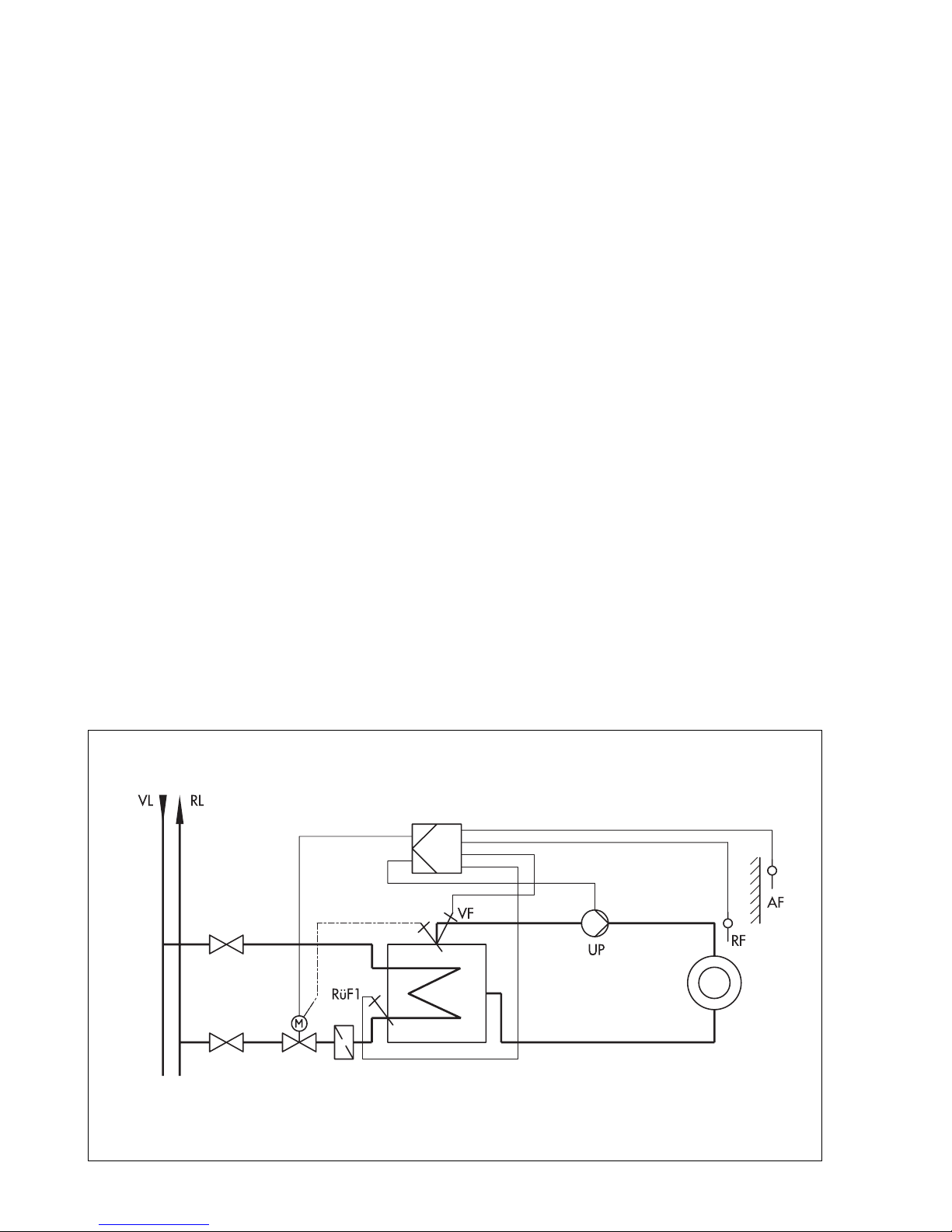
5.1 System code number 1.0
, only heating
Weather-compensated flow temperature control with variable limitation of the return flow temperature
Fig. 11 ⋅
(system code number 1.0)
Anl 1
20
Page 21

5.2 System code number 2.0
Weather-compensated flow temperature control with variable limitation of the return flow temperature and drinking water heating in a storage tank system
Fig. 12 ⋅
Anl 2.0
(system code number 2.0)
System c ode n umber 2.0 with cha ngeover valve
Weather-compensated flow temperature control with variable limitation of the return flow temperature and drinking water heating in a storage tank system with changeover valve
Fig. 13
⋅
Anl 2.0
(system code number 2.0) with changeover valve
21
Page 22

Drinking water heating process
Charging of the drinking water storage tank is started when the drinking water temperature in
the storage tank falls below the temperature value Drinking water heating ON or the value set
at a storage tank thermostat.
As a rule, the controller attempts to adapt the current flow temperature to the set Charging temperature before the storage charging pump starts to operate. In such operating situations, the
flow temperature of the heating circuit may be raised by up to 10 K, however, up to the set limit
Max. flow temperature at the maximum.
When the heating circuit is deactivated, the controller does not attempt this; the storage charging pump starts up immediately, or when a return flow sensor is connected and FB 20 = ON is
activated with the option "SLP" selected, it first starts to operate when the return flow temperature reaches the temperature at the storage tank sensor SF1.
With the default setting FB 9 = OFF harsh priority, i.e. the heating circuit is deactivated while
the drinking water heating is active long-term charging can be interrupted after 20 minutes
for 10 minute periods by the heating operation. For this, set the function block FB 9 = OFF, and
select the option "20". The same applies to the setting FB 9 = ON with the option "US" selected
system with a circulation pump and changeover valve.
With the setting FB 9 = ON and the option "PU" selected parallel pump operation the heating circulation pump only continues to run when the increase in flow temperature in the heating
circuit is maximum 10 K Max. flow temperature at the maximum.
Should the capacity available for parallel operation be too low, causing the charging temperature to remain more than 5 K under the set value, the heating operation is interrupted for 10
minutes. The time span before the parallel operation is terminated can be set in FB 9.
The storage tank charging stops when the drinking water temperature in the storage tank
reaches the temperature value Drinking water heating OFF or the preset value at the storage
tank thermostat. This occurs when the flow temperature demand of the heating circuit is correspondingly high because the storage charging pump has just been deactivated or in accordance with the parameter setting End charging process when the flow temperature demand of
the heating circuit is lower. In any case, the storage charging pump is deactivated, at the latest,
after two transit periods of the control valve 2xTy have elapsed.
22
Page 23

System code number 2.1
Weather-compensated flow temperature control system with variable limitation of the return
flow temperature and drinking water heating from the secondary circuit with differential temperature control for solar-powered heating of the drinking water storage tank system.
Solar collector
Fig. 14 ⋅
Anl 2.1
Solar collector
(system code number 2.1)
Fig. 15 ⋅
Anl 2.1
(system code number 2.1)
23
Page 24

If, in system code number 2, the drinking water heating takes place as already described with a
storage tank sensor (storage tank sensor SF1), the storage tank sensor SF2 can be used for the
solar-powered heating of the drinking water storage tank.
In addition to the "Drinking water heating process", the difference in temperature is determined
between the storage tank sensor SF2 and the solar collector sensor CF.
The solar circuit pump starts its two-stage operation depending on the parameter Solar circuit
pump ON:
Stage 2 is requested when the difference in temperature is twice as high as the value set in the
parameter Solar circuit pump ON.
If the difference in temperature falls below the value set in the parameter Solar circuit pump
ON, it switches back to stage 1.
The pump stops operating if the difference in temperature falls below the parameter Solar circuit pump OFF.
The solar circuit pump CP is, in principle, deactivated when the temperature measured at the
storage tank sensor reaches the parameter Solar charging OFF.
The time schedule for drinking water heating influences only the additional heating over the
storage tank sensor SF1, not the solar circuit.
The operating hours of the solar circuit pump CP can be retrieved by entering the code number
1990.
5.3 System code number 3.0
Weather-compensated flow temperature control with variable limitation of the return flow temperature and drinking water heating in the storage tank charging system
Fig. 16 ⋅
Anl 3.0
(system code number 3.0)
24
Page 25

Drinking wate r heating process
Charging of the drinking water storage tank is started when the drinking water temperature in
the storage tank falls below the temperature value Drinking water heating ON or the value set
at a storage tank thermostat.
The controller attempts to reduce flow temperatures that are higher than the set Charging temperature over the heating circuit before the heat exchanger charging pump together with the
storage charging pump start to operate.
When the heating circuit is deactivated as well as at lower flow temperature demands, the storage charging pump is activated immediately, while the storage charging pump is first activated
when the flow temperature reaches the temperature at the storage tank sensor SF1.
With the default setting FB 9 = OFF harsh priority, i.e. the heating circuit is deactivated while
the drinking water heating is active long-term charging can be interrupted after 20 minutes
for 10 minute periods by the heating operation. For this, set the function block FB 9 = OFF, and
select the option "20".
With the setting FB 9 = ON and the option "PU" selected parallel pump operation the heating circulation pump only continues to run when the increase in flow temperature in the heating
circuit is maximum 10 K Max. flow temperature at the maximum.
Should the capacity available for parallel operation be too low, causing the charging temperature to remain more than 5 K under the set value, the heating operation is interrupted for 10
minutes. The time span before the parallel operation is canceled can be set in FB 9.
The storage tank charging stops when the drinking water temperature in the storage tank reaches the temperature value Drinking water heating OFF or the preset value at the storage tank
thermostat. This occurs when the flow temperature demand of the heating circuit is correspondingly high because the storage charging pump has just been deactivated or in accordance
with the parameter setting End charging process when the flow temperature demand of the
heating circuit is lower. In any case, the storage charging pump is deactivated, at the latest, after two transit periods of the control valve 2xTy have elapsed; 15 seconds after the heat exchanger charging pump has been deactivated, the storage tank pump stops running.
25
Page 26

5.4 System code number 4.0
Weather-compensated flow temperature control with variable limitation of the return flow temperature and drinking water heating with return flow temperature limitation from the primary
circuit, designed as storage tank water heater
Fig. 17 ⋅
Anl 4.0
(system code number 4.0)
Drinking water heating process
The drinking water control valve causes a more or less fast charging of the drinking water storage tank from its closed position depending on the current system deviation and the set control
parameters when the drinking water temperature in the storage tank falls below the set point of
the Drinking water temperature.
Should the capacity available for a parallel operation of both circuits heating circuit and
drinking water circuit be too low when the maximum capacity is required, the function block
FB 8 can be activated.
With the setting FB 8 = ON and the option "Ab" selected Drinking water priority through setback operation the heating circuit is set to reduced operation for 20 minutes when there is a
system deviation of more than 5 K in the drinking water circuit: its capacity requirement is
moved back by reducing the current flow temperature by the value set in Set-back of flow temperature for reduced operation.
With the setting FB 8 = ON and the option "In" selected Drinking water priority through
reverse control the capacity requirement of the heating circuit is reduced when there is a system deviation of more than 5 K in the drinking water circuit. This is achieved by the three-point
stepping output of the drinking water circuit having an effect on the heating circuits control
valve in the opposite direction. The time span before the priority mode responds can be set in
Fb8.
26
Page 27

System code number 4.1
Weather-compensated flow temperature control with variable limitation of the return flow temperature and drinking water heating from the primary circuit with differential temperature control for solar-powered heating of the drinking water tank.
Solar collector
Fig. 18 ⋅
Anl 4.1
(system code number 4.1)
In addition to the "Drinking water heating process", the difference in temperature is determined
between the storage tank sensor SF2 and solar collector sensor CF. Both solar circuit pumps start
operating depending on the parameter Solar circuit pump ON. At the same time, the control
valve of the drinking water circuit is closed.
The solar circuit pumps stop running and the additional heating is enabled, provided their time
schedules allow this, when the difference in temperature drops below the value in the parameter
Solar circuit pumps OFF.
The operating hours of the solar circuit pump CP can be retrieved by entering the code number
1990.
27
Page 28

System code number 4.2
Weather-compensated flow temperature control with variable limitation of the return flow temperature and drinking water heating from the primary circuit with differential temperature control for solar-powered heating of the drinking water tank.
Solar collector
Fig. 19 ⋅
Anl 4.2
(system code number 4.2)
The difference to the system code number 4.1 is that the additional heating remains active even
during the operation of the solar circuit pumps, provided their time schedule allows it.
28
Page 29

5.5 System code number 5.0
Weather-compensated flow temperature control with variable limitation of the return flow temperature and drinking water heating from the primary circuit, designed as storage tank charging system
With FB19 = ON
Fig. 20 ⋅
Anl 5.0
(system code number 5.0)
Drinking wate r heating process
Charging of the drinking water storage tank is started when the drinking water temperature in
the storage tank falls below the temperature value Drinking water heating ON or the value set
at a storage tank thermostat. The storage tank charging pump starts operating immediately and
the Charging temperature is controlled.
Should the capacity available for a parallel operation of both circuits heating circuit and
drinking water circuit be too low when the maximum capacity is required, the function block
FB 8 can be activated.
With the setting FB 8 = ON and the option "Ab" selected Drinking water priority through setback operation the heating circuit is set to reduced operation for 20 minutes when there is a
system deviation of more than 5 K in the drinking water circuit: its capacity requirement is
moved back by reducing the current flow temperature by the value set in Set-back of flow temperature for reduced operation.
With the setting FB 8 = ON and the option "In" selected Drinking water priority through reverse
control the capacity requirement of the heating circuit is reduced when there is a system deviation of more than 5 K in the drinking water circuit. This is achieved by the three-point stepping
output of the drinking water circuit having an effect on the heating circuits control valve in the
opposite direction. The time span before the priority mode responds can be set in FB 8.
29
Page 30

Charging of the storage tank finishes when the drinking water temperature in the storage tank
reaches the temperature Drinking water heating OFF or the value preset at the storage tank
thermostat. With the default setting FB19 = OFF, the control valve of the drinking water circuit is
closed for this purpose.
The storage charging pump is deactivated when the charging temperature has dropped below
the value set in the parameter End charging process, or at the latest, after two transit periods of
the control valve in the drinking water circuit 2xTy have elapsed.
With the setting FB19 = ON Circulation via the heat exchanger the control of the charging
temperature is retained, if required, after intermediate reduction of the charging temperature as
set in the parameter End charging process.
5.6 System code number 6.0
Weather-compensated flow temperature control with variable limitation of the return flow temperature and drinking water heating from the primary circuit, designed as system with instantaneous water heater
Fig. 21 ⋅
Anl 6.0
(system code number 6.0)
30
Page 31

Drinking wate r heating process
The drinking water outlet temperature of the heat exchanger is controlled according to the set
point in the parameter Drinking water temperature. The setting of the control parameters concerning the achievable control quality is decisive for this.
Should the capacity available for a parallel operation of both circuits heating circuit and
drinking water circuit be too low when the maximum capacity is required, the function block
FB 8 can be activated.
With the setting FB 8 = ON and the option "Ab" selected Drinking water priority through setback operation the heating circuit is set to reduced operation for 20 minutes when there is a
system deviation of more than 5 K in the drinking water circuit: its capacity requirement is
moved back by reducing the current flow temperature by the value set in Set-back of flow temperature for reduced operation.
With the setting FB 8 = ON and the option "In" selected Drinking water priority through
reverse control the capacity requirement of the heating circuit is reduced when there is a system deviation of more than 5 K in the drinking water circuit. This is achieved by the three-point
stepping output of the drinking water circuit having an effect on the heating circuits control
valve in the opposite direction. The time span before the priority mode responds can be set in
FB 8.
The circulation pump ZP always runs according to its time schedule.
Observe the following for devices to be used in the drinking water control loop regarding the
drinking water temperature sensor VFTW and the control valve:
You must use a temperature sensor with fast response (we recommend a Pt100 sensor with z 09
= 2.3 seconds Type 5209) for measuring the drinking water outlet temperature. This is necessary in order to keep the duration of temperature peaks as well as the temperature peaks themselves as small as possible. In addition, an actuator with a transit time of max. 40 seconds is required.
We strongly recommend that the circulation pump be operated during times-of-use of the drinking water circuit!
31
Page 32

6. Operation
6.1 Operating controls
To access the operator controls, open the front cover of the controller.
Besides the mode switches, the following keys can be used to configure the controller.
Changeover key
Lets you change from the operating level to the parameter level or configuration
level
Reset key
Lets you reset all freely accessible parameters to default values (factory setting)
This keys function is active only on the parameter level!
Arrow keys
These keys let you adjust the displays as well as retrieve and set data by moving
up and down
Enter key
Operating level: lets you view adjusted set points
Parameter level: lets you access and acknowledge entered values and data
Configuration level: lets you access and acknowledge adjusted system code
numbers and function blocks
6.2 Selecting the operating modes
Use the mode switch to select the mode for each control loop (heating circuit or drinking water
heating circuit). Time-controlled operation is used as the default setting. The switch positions
with the assigned symbols mean the following:
Mode switch for the heating circuit
Time-controlled operation with switchover between
rated operation and reduced or standby operation
Rated operation
Reduced or standby operation
Manual operation: *
Control valve opens inactive closes, UP on
(for on/off control: + = ON, 0 = OFF)
32
* If the controller only reacts to these switch positions as in reduced or
standby operation, the manual level is locked. See chapter 7.3 on page
57 for more details.
Page 33

Mode switch for the drinking water heatin g circuit
Time-controlled operation with option to deactivate
drinking water heating circuit
Time-controlled operation, heating circuit deactivated,
only frost protection active
Heating and drinking water heating circuits deactivated,
only frost protection active
Manual operation: *
Control v alve opens inactiv e closes
(no function in
position 0 = drinking water circuit deactivated
position + = SLP and, if needed, TLP switched on)
* If the controller only reacts to these switch positions as in deactivated
mode (heating and drinking water heating circuits are deactivated), the
manual level is locked. See chapter 7.3 on page 57 for more details.
Set point correction switch
Heating circuit deactivated, only frost protection active
system 1
; in
system 2
and 3 only
Switch for set point correction during rated operation to
increase (+) or decrease () the set point as an alternative
to the mode switch for the drinking water heating circuit.
Switch symbol sticker is delivered with the controller.
See chapter 7.4 on page 58 about how to activate this switch
T
∆
flow max
T
∆
room max
= ±4 K x heating characteristic gradient (without adaptation)
= ±2 K (with adaptation)
6.2.1 Remote controlling the heating system
(only with room temperature sensot Type 5244 or Type 5257-4 with remote control)
You can change the operating mode or correct a set point of the heating circuit directly from the
room using the remote control.
Switch positions at the remote control are only effective when the mode switch at the controller is
set to the time-controlled operation symbol.
Time-controlled operation
Rated operation
Reduced or standby operation
Set point correction during rated operation periods
+ Increase room temperature Decrease room temperature
T
∆
flow max
T
∆
room max
= ±5 K x heating characteristic gradient (influencing range without adaptation)
= ±5 K (influencing range with adaptation)
33
Page 34

6.3 Control levels
Upon connection to the power supply during start-up, the controller automatically switches to
the operating level. To configure the controller, you must first switch over to the configuration
level and then the parameter level.
6.3.1 Configuration level:
You can adapt the controller to the individual system requirements
using the functions available.
6.3.2 Parameter level:
You can enter user data such as the time, date, heating characteristic,
set points, times-of-use, etc.
6.1.3 Operating level:
On this level, the controller is standard set to rated operation with timecontrolled switchover to reduced or standby operation.
Use the mode switches to change to other operating modes; times-of-use and current operating
states are indicated in the display.
As a rule, the basic display (Fig. 22) appears with the current time and bars indicating the current times-of-use as well as various operating states.
If you keep the key pressed down when the time appears in the display, the display alternates
between the current date and year.
If you want to display other values, e.g. current temperature values, proceed as follows:
Press the arrow key to view next display or
Press the arrow key to view the previous di splay
If you want to view the associated set point instead of the current temperature value, keep the
key pressed down.
If you continue to press the key, other images appear in the display with other symbols. These
depend on the system code entered during configuration (see chapter 7.1) as well as the adjusted function blocks.
Time schedule
Public holidays
Vaca ti on
Rated operation
Reduced or
standby operation
Frost protection
Sensor malfunction
1
Heating
demand
Heating pump
Val ve h ea ti ng
Fig. 22 ⋅ Basic display
34
10 1112 13 14 1516 17 1819123456789 20212223240
DW
circulation
pump (ZP)
Drinking water
demand
DW heat exchanger
charging pump
(TLP)/solar circuit
M
Storage charging pump (SLP)OPEN CLOSED
STOP
Summer time operation (heating circuit deactivated depending on
out sid e te mpe ratu re)
M
pump (CP)
Val ve fo r dri nk in g
water
Page 35

Operating level
Configuration level
Press both keys simultaneously
Current Anl
Fast setting
warmer/colder
1011 1213 14 1516 17 18 191 2 3 4 5 6 7 8 9 20 21 2223 240
1
M
Temperatures
heating
Temperatures
drinking water
M
Key held pressed:
Set point shown
Parameter level
Press key for 2 s
Key held pressed:
Date displayed
Enter current
time and date
Time
Enter
values
Data
heating
Function blocks
Time schedules
heating
Time schedules
drinking water
Public holidays
Vac ati ons
Time schedules
heating
Public holidays
Vac ati ons
Data
drinking water
Time schedules
drinking water
Fig. 23 ⋅ Control levels
35
Page 36

The most impor tant symbols and their mea ning:
Outdoor temperature
Meaning when key is kept pressed down.
Info Time-controlled summer time operation
Calculated outdoor temperature (only with
delayed outdoor temperature adaptation )
Flow temperature
Heating
Return flow temperature
(only with ret urn f low sensor)
(blinks when limitation is active)
Room temperature
(only with room sensor)
Storage tank temperature
(bottom)
Set point
(blinks in case of limitation of return flow,
flow rate or capacity)
Limit value
Set point
(only in adaptation and optimizing mode)
Drinking water heating ON / OFF
for system code nos. Anl 2.0, Anl 3.0 and
Anl 5.0
with just
one storage tank sensor
(SF1)
depending on deactivated/activated DW
heating
Drinking water heating OFF
for system code nos. Anl2.0, Anl3 and Anl5
with
two storage tank sensors
Solar circuit pump OFF
for system code nos. Anl 2.1, 4 .1 and 4.2
Storage tank temperature
(top)
Charging temperature
(only for Anl 2, 3 and 5)
For Anl2.1, Anl4.1, Anl4.2:
collector temperature
Drinking water temperature
(only for Anl6)
Flow rate/pulse rate
(only on flow rate or capacity
limitation)
(blinks when limitation is active)
Drinking water heating ON
for system code nos. Anl 2.0, 3.0 and 5.0
with two storage tank sensors
Drinking water heating ON / OFF
for system code no. Anl 2.1 depending on
deactivated/activated DW heating
Set point for system code no. Anl 4
Set point (for system code nos. Anl 2 and 3
only during activated DW heating)
Solar circuit pump ON
Set point
Limit value
36
Page 37

Increase/decrease heatings set point on the operating level
The room temperature can be adjusted from the operating level by simply pressing a few keys.
This is achieved by changing the flow temperature of the heating circuit via displacement of the
heating characteristic to make it warmer or cooler, or in adaptation mode, by directly changing
the room temperature set point.
This setting is only effective when the heating system is running during a rated operation period!
10 1112 13 1415 16 17 18191 2 3 4 5 6 7 8 9 20212223240
Operating level, e.g. time shown in the display
If you want to change the set point:
Press the arrow key until the gradient of the
heating characteristic or room set point (see
1
M
M
below) appears in the display.
Press the enter key. The displacement arrows
start to blink.
10 1112 13 1415 16 1718 1912345 6789 20212223240
°C
Use the arrow keys to set the required
displacement value in °C . Upwards = increase
and downwards = decrease room temperature.
A displacement by 5 °C, for example, causes a 1°C increase in the room temperature.
1
M
M
Press the enter key to acknowledge the value.
Shortly after, the display returns to the current
time.
10 1112 13 1415 16 17 18191 2 3 4 5 6 7 8 9 20212223240
°C
Press the enter key. The room temperature
arrow starts to blink.
1
M
Use the arrow keys to set the required value
in °C.
Press the enter key to acknowledge the value.
M
Shortly after, the display returns to the current
time.
37
Page 38

7. Star ting up and confi guring the control ler
Switch on the power supply to start up the controller.
After briefly switching between displays, the controller automatically goes to the operating level
and the time appears in the display.
You must first configure the controller before setti ng it.
Then enter any required user data as described in chapter 7.2 on parameterization.
7.1 Configuration
Configure the controller to adapt its functions to the requirements of the system. To do this, select
the appropriate system diagram from the system descriptions in chapter 5 (Figs. 11 to 21).
After this, determine the functions required for the chosen system diagram by activating and setting certain function blocks.
The set system code number as well as the function blocks FB 20 to FB 23 are protected by
Note:
a
code number
.
You can only access the settings for the system code numbers, function blocks and all the data
required for parameterization and configuration after entering a valid code number!
If you cannot change any function block settings in the parameter level and various par-
Note:
ameters are not shown in the display, the write protection function for the configuration level is
enabled. See chapter 7.3 on page 57 for more details.
7.1.1 Setting the code number
The valid code number is written on page 62 of this manual. If you want to keep this code number, but prevent any unauthorized person from using it, cut out or scribble out the number on
page 62.
Personal code number:
You can enter your own personal code number. See chapter 7.3 on
page 57 for more details.
0 0 0 0
appears in the display after you have selected a system code number or a protected
function block
1011 1213 141516 1718 191 2 3 4 5 6 7 8 9 2021 2223 240
Press the arrow key until you approximately
reach the code number (the longer you press the
key, the faster the displayed number changes) .
Use the arrow keys to set the number.
Press the enter key to acknowledge the set code
number.
38
Page 39

7.1.2 Setting the system code number (Anl)
Use a pencil (or similar item) to press the changeover key. A triangle (parameter level)
starts to blink in the top left-hand corner of the display.
Press the arrow keys simultaneously; two triangles (configuration level) start to blink
and the currently active system code number is shown in the display.
If you want to keep the system code number shown in the display:
Press the arrow key. Bars indicating the associated function blocks appear in the display.
If you want to change the system code number shown in the display, you must first enter the code
number. See also chapter 7.1.1:
Press the enter key.
0 0 0 0
appears in the display.
Press the arrow key until you approximately reach the code number (the longer you
press the key, the faster the displayed number changes).
Use the arrow keys to set the code number.
Press the enter key to acknowledge the set code number.
blinks in the display.
Anl
Use the arrow keys to set the system code number of the selected system diagram
(Anl 1 to Anl 6, Figs. 11 to 21).
Press the enter key to acknowledge the system code number.
Bars indicating the associated function blocks for that system appear in the display.
7.1.2 Setting the function blocks
Directly after you have set and acknowledge the system code number, bars appear in the display together with the basic setting of the associated function blocks.
If you select additional sensors and/or functions that are not included in the basic setting, do not
forget to set the corresponding function blocks (ON or OFF). Refer to the following list for further
explanations about the function blocks.
The black bars under the numbers 1...24 at the top of the display mean the function blocks are
activated (ON). Blank areas under the numbers mean the function blocks are deactivated
(OFF).
Configuration level
(blinks)
Fig. 24 ⋅ System code number and function block settings
10111213141516171819123456789 20212223240
Current
function block number
e.g.
function block 14 ON
System code number
39
Page 40

If you want to change the basic setting of a function block, proceed as follows:
Use a pencil (or similar item) to press the changeover key. A triangle (parameter level)
starts to blink in the top left-hand corner of the display.
Press the arrow keys simultaneously; two triangles (configuration level) start to blink
and the currently active system code number is shown in the display.
Press the arrow key. Bars indicating the function blocks appear in the display.
Use the arrow keys to set the number of the function block you want to change.
Press the enter key. The function block number starts to blink.
Press the arrow key to switch the function block
Press the arrow key to switch the function block
ON
OFF
or
Press the enter key to acknowledge the setting.
Use the arrow keys to select the next function block.
Proceed as described above to switch a function block ON or OFF.
Note:
Certain function blocks require that you set the parameters directly after you have activated
them. Observe the instructions in the function block list before setting these parameters.
Parameters that must be set start to blink with their symbol in the display.
If you want to change the default setting shown:
Use the arrow keys to set the new value.
Press the enter key to acknowledge the new value.
1011 1213 141516 1718 191 2 3 4 5 6 7 8 9 2021 2223 240
1011 1213 141516 1718 191 2 3 4 5 6 7 8 9 2021 2223 240
START
40
Example:
The function block setting FB 3 = ON is acknowledged
using the key (time-controlled summer time operation)
The date when the summer time operation should start
appears in the display.
Use the arrow keys if you want to change the
date,
following this or alternatively
Press the enter key to acknowledge the date.
Page 41

START
1011 1213 141516 1718 191 2 3 4 5 6 7 8 9 2021 2223 240
The number of days to activate the time-controlled summer time operation appears in the display
Use the arrow keys if you want to change the
number,
following this or alternatively
Press the enter key to acknowledge the number.
STOP
STOP
1011 1213 14151617 1819123456789 20212223240
The number of days to deactivate the time-controlled
summer time operation appears in the display
Use the arrow keys if you want to change the
number,
following this or alternatively
Press the enter key to acknowledge the number.
1011 1213 14151617 1819123456789 20212223240
The number of days to start the heating appears in the
display
Use the arrow keys if you want to change the
number,
following this or alternatively
Press the enter key to acknowledge the number.
1011 1213 141516 1718 191 2 3 4 5 6 7 8 9 2021 2223 240
o
C
The limit value of the outdoor temperature appears in the
display
Use the arrow keys if you want to change the
limit value,
following this or alternatively
1
Press the enter key to acknowledge the limit value.
Function block FB 3 reappears in the display.
1011 1213 141516 1718 191 2 3 4 5 6 7 8 9 2021 2223 240
Use the arrow keys to select the next function
block ...
Exiting the configuration level
Press the changeover key. This lets you enter the parameter level.
Press the changeover key again to exit the parameter level. The basic display
of the operating level appears in the display.
If you do not press any keys for 5 minutes, the controller automatically returns to the operating
level and the current time appears in the display (basic display)
41
Page 42

7.1.3 Function block list
Legen d: FB F uncti on blo c k numb er FS Factor y (de f ault) s ettin g An l Syste m code number
FB Function FS Anl Comment
0 Optimize
(Chapter 4.1)
1 Adaptation
(Chapter 4.2)
2 Flash adaptation
(Chapter 4.2)
3 Summer time
operation
(Chapter 4.4)
4 Delayed outdoor
temperature
adaptation
(Chapter 4.7)
OFF If FB 0 = ON is selected, FB13 is automatically
activated and cannot be deactivated
OFF If FB 1 = ON is selected, FB13 is automatically
activated and cannot be deactivated
OFF If FB 2 = ON is selected, FB13 is automatically
activated and cannot be deactivated. FB 2 = ON
directly determines after how many minutes a
1°C change in flow temperature by 1 °C should
occur.
1 to 100 minutes (default: 10 min
)
OFF FB 3 = ON directly determines how long the
summer time operation should be effective:
(default: 01.06.to 30.09.), the number of days,
setting range 1 to 3 days to activate/deactivate
the function (default: 2/1) as well as outdoor
temperature limit 0 to 30 °C (default: 18 °C)
OFF FB 4 = ON allows you to select the function just
when the outdoor temperature drops (Ab) or
when the outdoor temperature rises or drops
(AufAb). Then enter delay from 1 to 6 °C/h
(default: 3 °C/h)
5Automatic clock
reset summer
time/winter time
6 Public holiday and
vacation schedule,
valid for drinking
water heating
7Thermal
disinfection
ON FB 5 = ON to activate the automatic clock reset
summer time/winter time
OFF FB 6 = ON to allow the drinking water heating to
run during public holidays using Sunday
settings; the drinking water heating is
deactivated completely during vacation periods
OFF If FB 7 = ON is selected, FB14 is automatically
activated and cannot be deactivated (storage
tank thermostat not possible).
FB 7 = ON to select the settings for day of week,
setting 1 7 = daily,
setting 1 = Monday, (default: 3), start time
(default: 0:00 hrs), stop time (default: 4:00 hrs),
as well as deactivating temperature 60 to 90 °C
(default: 70 °C)
42
Page 43

8Priority for
drinking water
control circuit
(See description of
system diagrams in
chapter 5)
OFF Only
4, 5, 6
FB 8 = ON allows you to select priority for
drinking water using set-back operation (Ab)
or priority for drinking water through reverse
control (In). Then enter time span 2 to 10 min
(default: 10 min) before priority operation
should respond
9 Parallel pump
operation
(See description of
system diagrams in
chapter 5)
10 3-point stepping
control of the
heating circuit,
control parameter
OFF Only
2 + 3
FB 9 = ON allows you only in Anl 2 to select a
parallel pump operation (PU) or operation with a
changeover valve (US). The setting "PU" in Anl 2
or FB 9 = ON in Anl 3 requires you to enter data
for:
Time span 2 to 10 min (default: 10 min)
before parallel operation should be canceled.
Finally you must determine whether the
operating phases in which parallel operation is
not possible should take place with or without
intermediate heating. Option: "20" or " "
With FB 9 = ON "US" and with FB 9 = OFF you
must first determine the parameters concerning
intermediate heating:
"20" activates it after 20 min,
" " means no intermediate heating takes
place.
ON The heating circuit functions as a three-point
stepping control loop when FB 10 = ON. Then
enter data for:
Kp = 0.1...50.0 (default: 2.0),
Tn = 1...999 sec (default: 200 ),
Ty = 15, 30, 45, ..., 240 sec (default: 90 s),
Pump lag time = Ty, 2 x Ty, 3 x Ty, up to
10 x Ty (default: 180 sec)
The heating circuit functions as an on/off control
loop when FB 10 = OFF.
Then enter differential gap =
1 to 30 °C (default: 5 °C).
11 Limitation of
system deviation
for OPEN signal
heating circuit (in
Sys. 3 and 3 also
drinking water
heating)
12 Limitation of
system deviation
for OPEN signal
(drink. water circuit)
OFF FB 11 can only be activated when FB 10 = ON.
If FB 10 = OFF is selected, FB 11 is automatically
deactivated and cannot be activated.
The limitation of the system deviation to
2...10 °C is determined when FB 11 = ON
(default: 2 °C)
OFF Only
4, 5, 6
The limitation of the system deviation to
2...10 °C is determined when FB 12 = ON
(default: 2 °C)
43
Page 44

13 Room sensor RF OFF When FB 13 = ON, the room temperature
display does not affect the control loop; when
Type 5244 or Type 5257-4 Sensors with remote
control are connected, the remote adjustment of
operating modes is additionally activated
14 Storage tank
sensor SF1
(See chapter 5 for
description on switching
behavior)
15 Storage tank
sensor SF2
(See chapter 5 for
description on switching
behavior)
ON 2, 3,
4.1,
4.2, 5
ON 2, 3,
4.1,
4.2, 5
When FB 14 = ON, the sensor SF1 is activated.
Fb14 cannot be deactivated in Anl 2.1, 4.1 and
4.2. It can only be deactivated in all other
systems when FB 15 = OFF. Set FB 14 = FB 15 =
OFF when storage thermostat is used!
When FB 15 = ON, the sensor SF2 is activated.
Fb 15 cannot be deactivated in Anl 2.1, 4.1, 4.2
16 Sensor selection OFF When FB 16 = OFF, PTC and Pt100 sensors can
be connected, mixed circuit is possible.
When FB 16 = ON and "P1000" is selected,
Pt1000 and Pt 100 sensors can be connected,
when "ntc" is selected, NTC and Pt 100 sensors
can be connected, mixed circuit is possible
17 3-point stepping
control for
drinking water
circuit, control
parameters
ON Only
4, 5, 6
When FB 17 = ON, the drinking water circuit
functions as 3-point stepping control loop. Enter
the following:
K
= 0.1...50.0 (default: 2.0),
P
T
= 1...999 sec (default: Anl 5, 6: 60 sec;
N
Anl 4: 200 sec), Ty = 15, 30, 45, ..., 240 sec
(default: Anl5, 6: 30 sec; Anl4: 90 sec)
When FB 17 = OFF, the drinking water circuit
functions as on/off control loop.
Enter differential gap = 1 to 30 °C (default:5 °C)
18 Outdoor
OFF When FB 18 = OFF, the sensor input for outdoor
temperature
signal input
19 Circulation
OFF 5 When FB 19 = ON, the control release of the
via heat exchanger
(See chapter 5 for
description)
44
temperature measurement is activated.
When FB 18 = ON, the signal input for outdoor
temperature measurement is activated.
Option between 0 or 4 to 20 mA signal
connection
(Measuring range: 20...+50 °C).
Connect a 50 Ohm resistance to terminals 3 (+)
and GND (terminals 5 to 8) parallel to signal!
drinking water circuit is retained even after
active storage tank charges
Page 45

You will be prompted to enter a code number when you select one of the following function
blocks
!
20 Return flow sensor
RüF
(See chapter 4.8)
21 Return flow
temperature
limitation in
drinking water
circuit by means of
RüF1 (RüF2 in
Anl 4.0)
(See chapter 4.8)
22 Signal input for
flow rate
measurement
(See chapter 4.15)
ON When FB 20 = ON, the return flow sensor RüF is
activated. Set the limitation factor, setting range
0.1 to 10 (default: 1). In Anl2, you can select
afterwards between "SLP" (default) SLP
activated depending on return flow temperature
with drinking water demand and deactivated
heating circuit and " " immediate
activation of SLP with drinking water demand
and deactivated heating circuit.
ON
OFF
4.0, 5In Anl4.0 when RüF2 is activated, set the
limitation factor = 0.1 to 10 (default: 1); In Anl 5
FB 21 can only be activated when FB 20 = ON. It
is only appropriate when the return flow sensor
RüF1 is installed in the common return flow pipe.
FB 21 is automatically deactivated and cannot
be activated when FB 20 = OFF
OFF When FB 22 = ON, the signal input is defined
for flow rate measurement.
Furthermore, you can select between 0 or 4 to
20 mA signal connection. This function can only
be activated with FB23!
Connect a 50 Ohm resistance to terminals 12 (+)
and GND (terminals 5 to 8) parallel to signal!
When FB 22 = OFF, the pulse input is defined for
limitation. This function can only be activated
with FB23!
23 Limitation of
capacity or
flow rate
(See chapter 4.15)
OFF When FB 23 = ON and FB 22 = OFF, the pulse
rate limitation is activated.
You must then set the limit value for heating, its
associated limitation factor and, if needed, the
limit value for drinking water heating and its
associated limitation factor. Respective setting
ranges 3 to 500 pulse/hr and 0.1 to 10!
When FB 23 = ON and FB 22 = ON, the flow
rate limitation via current signal is activated.
You must determine upper measuring range
value setting range 0.1 to 100 m
3
/hr ,
the flow rates minimum limit value and
maximum limit value
Setting ranges for both 0.01 to 100 m
3
/hr
45
Page 46
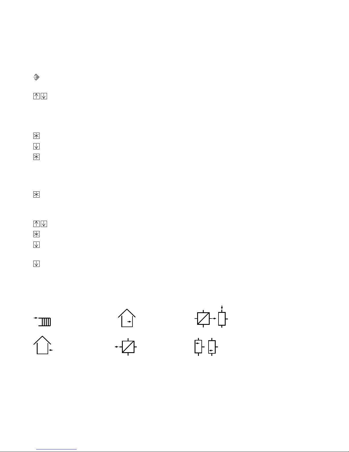
7.1.4 Sensor calibration
The measured values of all of the connected sensors can be changed or reset. When calibrating
a sensor, change the sensor value currently displayed to make it match the temperature (reference value) measured directly at the point of measurement.
Enter the code number 1999 in the configuration level to calibrate sensors.
To do this, proceeds as follows:
Use a pencil (or similar obje ct) to press the changeover key, a triangle ( parameter
level) starts to blink in the top left-hand corner of the display.
Press the arrow keys simultaneously, two triangles (configuration level) start to blink in
the display as well as the currently active system code number.
Press the enter key.
0 0 0 0
Press the arrow key once. The code number
appears in the display.
1999
appears.
Press the enter key to acknowledge this code number.
The symbol for the flow temperature appears in the display together with its current
temperature (initially without calibration).
Press the enter key to acknowledge the sensor shown for calibration.
The actual temperature (used as the reference value) must be read from a thermometer
directly at the point of measurement.
Use the arrow keys until the displayed value matches the reference value.
Press the enter key to acknowledge the corrected temperature value.
Press the arrow key to continue to the next sensor. Proceed with the calibration as
described above.
Press the arrow key to exit the calibration menu.
Sensor symbols
VF
Flow sensor
AF
Outdoor sensor
46
RF
Room sensor
RüF
Return flow
sensor
VFTW Flow sensor
drinking water circuit
CF Solar circuit
collector sensor
SF1 SF2
Storage tank sensor
Page 47
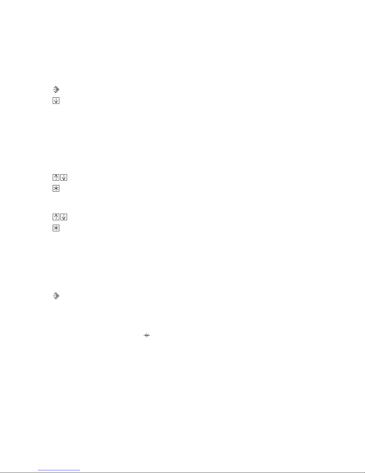
7.2 Parameterization
Only the system-specific parameters are displayed in the parameter level depending on the
configuration carried out beforehand.
You automatically enter the parameter level when you exit the configuration level.
A blinking triangle in the top left-hand section of the display indicates that you are in the parameter level.
If you are still in the operating level:
Press the changeover key to access the parameter level.
Press the arrow key, the first parameter (time) appears in the display.
In the following summary (chapter 7.2.2), all the parameters are listed in the same sequence as
they appear when you enter user data.
Only the parameters that correspond to the preset system configuration in chapter 5.3 are taken
into account when you enter new data.
How to enter data in the parameter level:
Use the arrow keys to access the parameter you want to change.
Press the enter key to acknowledge the parameter,
the corresponding symbol starts to blink in the display when the parameter value
can be changed.
Use the arrow keys to set the value as required.
Press the enter key to acknowledge the set value,
the next parameter appears in the display.
Proceed as described above.
Note:
If you do not press any keys for five minutes, the controller automatically leaves the parameter
level.
Press the changeover key again to enter the parameter level.
7.2.1 Resetting to default values
If you are in the parameter level, you can reset all parameters you have entered to return to the
default settings by pressing the reset key.
The protected parameter values are only affected by this if the code number you entered beforehand is still valid. (The code number becomes invalid five minutes after the last entry!) The function block settings are still stored.
The controller is basically ready for operation with default values (factory setting). However,
you are still required to enter the current time and date as the first paramete rs.
The default values are listed in the following summary.
47
Page 48

7.2.2 Entering and modifying user data
The individual parameters are listed together with their symbols and default setting!
Press the changeover key, the blinking triangle indicates that you are in the parameter
level, a time appears in the display.
Entering current time and date
You are required to enter these data on start-up and when a power supply failure has occurred
lasting longer than 24 hours!
1011 1213 14151617 1819123456789 20212223240
Press the enter key, the clock symbol blinks.
Use the arrow keys to set the correct time.
Press the enter key to acknowledge the time,
a date now appears in the display.
Use the arr ow keys to set the c orrect date .
Press the enter key to acknowledge the date,
the year now appears in the display.
Use the arrow keys to set the correct year.
Entering parameters for heating circuit:
1011 1213 141516 1718 19123456789 20212223240
Gradient of the heating characteristic
The correlation between the outdoor temperature and
the flow temperature is determined by a gradient value
from 0.2 to 3.2.
If you want to change it:
(You can only change it when the adaptation function is
deactivated)
Flow temperature
[˚C]
130
120
110
100
90
80
70
60
50
40
30
20
20 16 12 8 4 0 -4 -8 -12 -16 -20
3.2 2.9 2.6
2.4
2.2
2.0
1.8
1.6
1.4
1.2
1.0
0.8
0.4
0.2
[˚C]
Press the enter key to acknowledge the year
the next parameter now appears in the display.
Press the enter key, the gradient arrow blinks.
Use the arrow keys to set the required
characteristic value.
Press the enter key to acknowledge the value.
Heating characteristics
Outdoor temperature
48
Page 49

1011 1213 141516 1718 191 2 3 4 5 6 7 8 9 2021 2223 240
Level of t he he at ing c hara cter istic
°C
Parallel displacement of the heating characteristic determined by the displacement value upwards (positive
value) or downwards (negative value) (30 to +30 °C )
If you want to change it:
Press the enter key, the displacement arrows
start to blink.
Use the arrow keys to set the required displace-
ment value in °C.
Press the enter key to acknowledge the value.
You can only change this setting when the flash adapta-
(
tion is not activated)
Proceed in the same manner to enter the following parameters!
1011 1213 14151617 1819123456789 20212223240
°C
Max. flow temperature
(20 to 130 °C)
STOP
If you set the max. value = min. value, this results in a
fixed value
1011 1213 141516 1718 191 2 3 4 5 6 7 8 9 2021 2223 240
°C
Min. flow temperature
(20 to 130 °C)
1011 1213 141516 1718 191 2 3 4 5 6 7 8 9 2021 2223 240
°C
Set-back of flow temperature
for reduced operation
(0 to 50 °C)
See chapter 4.3 on reduced operation
1011 1213 141516 1718 19123456789 20212223240
°C
Outdoor temperature limit value for summer time
operation
(0 to 50 °C)
1
See chapter 4.4 on summer time operation
49
Page 50

STOP
1
1011 1213 14151617 1819123456789 20212223240
°C
Outdoor temperature limit value
for deactivation in reduced operation
(10 to 50 °C)
START
1
1011 1213 14151617 1819123456789 20212223240
°C
Outdoor temperature l imit value
for return to rated operation
(30 to 50 °C)
1011 1213 141516 1718 191 2 3 4 5 6 7 8 9 2021 2223 240
°C
1011 1213 141516 1718 191 2 3 4 5 6 7 8 9 2021 2223 240
°C
Room se t point
(0 to 40 °C)
Reduced room set point
(0 to 40 °C)
See chapters 4.1 and 4.2 on optimize and adaptation
modes
1011 1213 141516 1718 191 2 3 4 5 6 7 8 9 2021 2223 240
°C
1011 1213 141516 1718 191 2 3 4 5 6 7 8 9 2021 2223 240
Sustained temperature
(0 to 40 °C)
Gradient of the return flow characteristic
for limitation of return flow temperature
(0.2 to 3.2) You must first enter the code number before
you can change this value.
The correlation between outdoor temperature and return
flow temperature is determined corresponding to the
flow temperature by the gradient value. See chapter 4.8
on limitation of the return flow temperature.
50
Page 51

1011 1213 141516 1718 191 2 3 4 5 6 7 8 9 20212223240
°C
Level of t he return flow charac teristic
(30 to 30 °C) You must first enter the code number before you can change this value.
1011 1213 141516 1718 19123456789 20212223240
°C
Max. return flow temperature
(20 to 90 °C) You must first enter the code number before
you can change this value.
If you set the max. value = min. value, this results in a
fixed limit value
1011 1213 141516 1718 19123456789 20212223240
°C
Min. return flow temperature
(20 to 90 °C) You must first enter the code number before
you can change this value.
Time schedule for heating
Times-of-use of the heating
1011 1213 141516 1718 191 2 3 4 5 6 7 8 9 2021 2223 240
You can enter two time periods for the time-controlled
operation (mode switch set to clock symbol), during
which the heating runs in rated operation.
The default setting is a daily rated operation from
to 22:00 hrs
.
6:00
The heating runs dependent on the outdoor temperature
1
according to the predetermined heating characteristic
(see page 48).
The heating is switched over to reduced operation when the default rated operation time period
ends at 22:00 hrs. This saves energy in the times of non-use, e.g. at night time.
In reduced operation, the heating runs, for example with a set-back of the flow temperature by
15 °C. The values for the reduced operation are preset as set-back of flow temperature
for reduced operation (page 49).
The heating switches back to rated operation when the reduced operation ends at 7:00 hrs.
51
Page 52

You can enter the time schedules in time blocks
(Mon Sun),
1 7
(Sat Sun) or as individual days 1 (Mon), 2 (Tue), 3 (Wed), etc.
Use the arrow keys to select the required time block.
(Mon Fri) and
1 5
6 7
For the rated operation, enter the time periods that alternate between
START
and
STOP
. If you
do not require the second period, acknowledge the STOP of the first period and the START of the
second period at 12:00 hrs (default).
Note:
Later, you can only check time blocks (START STOP) that you have already entered with
the individual day entry and by calling up each individual day using the keys.
If you want to change the default times:
Press the enter key
After accessing the parameter level, activate the parameter for the time schedule for heating.
appears in the display.
1 7
If you want to continue to another time block:
Press the arrow key until you reach the required
1011 1213 1415 161718191 2 3 4 5 6 7 8 9 20 2122 23240
block
5 6, 6 7
or 1-, 2 etc.
If you want a change to be effective daily at the same
time, select time block
, for example.
1 7
Press the enter key to access the selected
0 1 2 3 4 5 6 7 8 9 10 11 12 13 14 15 16 17 18 19 20 21 22 23 24
block.
The starting time for the first time period appears in the
display.
START
appears, the clock symbol blinks. The
current set time period is indicated in the display as bars.
Use the arrow keys to set the time when the rated operation should start (30 min
increments, the bars indicate how the time block is progressing).
Press the enter key to acknowledge the set time,
STOP
and a time (default 12:00 )
appear in the display.
Use the arrow keys to set the time when the first period should end.
Press the enter key to acknowledge the set time,
START
and a time (default 12:00 )
appear in the display.
Use the arrow keys to set the time when the second period should start.
Press the enter key to acknowledge the set time,
STOP
and a time (default 22:00 )
appear in the display.
Use the arrow keys to set the time when the second period should end.
Press the enter key to acknowledge the set time.
Then at the enter block for individual days (1, 2, 3 etc.),
Press the arrow key to exit the menu for the time schedule for heating.
52
Page 53

Public holidays
1011 1213 1415 161718191 2 3 4 5 6 7 8 9 20 2122 23240
Entering additional days:
Press the enter key, the first set
date appears in the display.
Press the arrow key until
appears.
Press the enter key, the public holiday
symbol starts to blink in the display.
Use the arrow keys to set additional
public holidays.
Press the enter key to acknowledge
the date.
Set any additional public holidays as
described above.
Default:
Deleting set days:
Use the arrow keys until
Press the enter key, the first set date
appears in the display.
Press the arrow key to find the public
holiday you want to delete.
Press the enter key, the public holiday
symbol starts to blink.
appears in the display.
(
is between 31.12 and 01.01)
Press the enter key to delete the
holiday.
Vacations (max. 10 vacation periods possible)
1011 1213 1415 161718191 2 3 4 5 6 7 8 9 20 2122 23240
Default:
Entering vacation periods:
Press the enter key, the start of the
first vacation appears in the display.
Press the arrow key until
appears.
Press the enter key, the vacation symbol
symbol starts to blink.
Press the arrow key to set the date
when the vacation should start.
Press the enter key to acknowledge
the date. The vacation symbol blinks and
STOP appears in the display.
Use the arrow keys to set the date
when the vacation should end.
Deleting vacation periods:
Press the enter key, the start of the
first vacation appears in the display.
Press the arrow key to find the start
of the vacation you want to delete.
Press the enter key, the vacation
symbol starts to blink.
Use the arrow keys until
appears in the display.
(
is between 31.12 and 01.01)
Press the enter key to delete a
vacation period.
Press the enter key to acknowledge
the date.
Set any additional vacations as described
above.
53
Page 54

Entering parameters for drinking water circuit:
1011 1213 14151617 1819123456789 20212223240
°C
Drinking wa ter heating ON
(20 to 90 °C)
In systems 2 .0,
3 and 5 with just one storage tank sensor SF1
followed by
1011 1213 141516 1718 19123456789 20212223240
°C
Differential gap
(0 to 30 °C)
In systems 2.0,
3 and 5 with just one storage tank sensor SF1
1011 1213 141516 1718 191 2 3 4 5 6 7 8 9 2021 2223 240
°C
Drinking wa ter heating ON
(20 to 90 °C)
In systems 2, 3 and 5 with two storage tank sensors SF1
and SF2
1011 1213 14151617 1819123456789 20212223240
°C
Drinking wa ter heating OFF
(20 to 90 °C)
In systems 2.0,
3 and 5 with two storage tank sensors SF1 and SF2
1011 1213 141516 1718 19123456789 20212223240
°C
alternatively
Differential gap
(0 to 30 °C)
In system 2.1
1011 1213 141516 1718 191 2 3 4 5 6 7 8 9 2021 2223 240
54
°C
Drinking wa ter temperature
(20 to 90 °C)
In systems 4 and 6
System 4
System 6
Page 55

1011 1213 141516 1718 191 2 3 4 5 6 7 8 9 2021 2223 240
°C
Charging temperature set point
(20 to 90 °C)
In systems 2, 3 and 5
STOP
START
1011 1213 1415 1617 1819123456789 20212223240
°C
End charging process
(20 to 90 °C)
In systems 2, 3 and 5
1011 1213 141516 1718 19123456789 20212223240
°C
Return flow limitation temperature during drinking
water heating
(20 to 90 °C) You must first enter the code number before
you can change this value.
In systems 2, 3, 4.0 and 5
See chapter 4.8 on limitation of the return flow tempera-
1011 1213 141516 1718 19123456789 20212223240
°C
ture
Solar circuit pump ON
(0 to 30 °C)
STOP
STOP
In systems 2.1, 4.1 and 4.2
1011 1213 141516 1718 19123456789 20212223240
Solar circuit pump OFF
°C
(0 to 30 °C)
In systems 2.1, 4.1 and 4.2
1011 1213 141516 1718 19123456789 20212223240
°C
Solar charging OFF
(20 to 90 °C)
In systems 2.1, 4.1 and 4.2
55
Page 56

1011 1213 141516 1718 19123456789 20212223240
Time schedule for drinking water heating
Default rated operation 1 7 00.00 24.00
Enter as described for time schedule for heating
on page 51.
1011 1213 14151617 1819123456789 20212223240
Time schedule for circulation pump
Default rated operation 1 7 00.00 24.00
Enter as described for time schedule for heating
on page 51.
56
Page 57

7.3 Personal code numbers, locking the mode switch for manual operation, enabling the
write protect function for the configuration lev el and masking out parameters
You can only choose a personal code number between 100 and 1900!
Note:
You must first enter the code number
before you can enter a personal code number or re-
1995
strict the access.
To do this, proceed as follows:
Use a pen (or a similar item) to press the changeover key, a triangle (parameter level)
starts blinking in the top left-hand corner of the display.
Press both keys simultaneously, two triangles (configuration level) start blinking
in the display. The currently active system code number appears in the display.
Press the enter key,
0 0 0 0
Press the arrow key five times, the code number
appears in the display.
1995
appears in the display.
Press the enter key to acknowledge the code number,
the code number
0 0 0 0
reappears in the display.
Use the arrow key to set the code number (from page 62 or a new one).
Press the enter key, the code number starts to blink .
Use the arrow keys to set a new personal code number
or, if you do not want to change it.
Press the enter key to acknowledge the code number.
You can now lock the manual level, if required, as described below.
Locking the manual level
When the locking is activated, the mode switch positions
and stand for in the heating
+, 0
circuit and in the drinking water heating circuit.
The manual level is activated when
the manual level is locked when
Press the enter key, the
HAnd
Use the arrow keys to change between
appears in the display,
HAnd
appears in the display.
or
starts to blink.
HAnd
and
.
Press the enter key to acknowledge the setting selected.
Now you can enable the write protect function for the configuration level, if required, which
also masks out parameters.
Enabling the write protect function for the configuration l evel
Only the system code number
appears in the configuration level when the write protect
Anl
function is enabled. The function blocks appear in the display on pressing the key, but you
cannot change the parameter settings anymore at this point.
57
Page 58

In the parameter level, all the parameters in the display are masked out except for the following
parameters: Time/Date/Year, Heating characteristic gradient, Heating characteristic level,
Set-back of flow temperature for reduced operation - alternatively Room set point and Sustained temperature - the drinking water set points (Drinking water heating ON and Differential gap or Drinking water heating ON and Drinking water heating OFF in Anl2, Anl3 and
Anl5, Drinking water temperature in Anl4 and Anl6), as well as Time schedules, if applicable
Public holidays and Vacations.
The configuration level is not write protected when
the write protect function is enabled when
appears in the display.
COPA
appears in the display,
Press the enter key, the display blinks.
Use the arrow keys to change between
COPA
and
.
Press the enter key to acknowledge the setting selected.
7.4 Configuring the correction switch
(The correction switch label is delivered with the controller)
First enter the code number
to configure the switch.
1998
Proceed as described below:
Use a pen (or a similar item) to press the changeover key, a triangle (parameter level
starts blinking in the top left-hand corner of the display.
Press both keys simultaneously, two triangles (conf iguration level) start blinking
in the display. The currently active system code number appears in the display.
Press the enter key,
0 0 0 0
Press the arrow key twice, the code number
appears in the display.
1998
appears in the display.
Press the enter key to acknowledge the code number.
The mode switch for drinking water heating is activated if
The correction switch is activated if
Use the arrow keys to change between
appears in the display.
corrS
btrS
Press the enter key to acknowledge the setting selected.
and
corrS.
appears in the display.
btrS
58
Page 59

8. Data transfer using memory module
To simplify configuration and parameterization of the controller, you can use the memory module 1400-7142 or 1400-7436 for data transfer between controller and module or controller
and PC.
The memory module 1400-7142 has a Sub-D 25-pin female connector to connect it to a PC
and a modular jack to connect it to the controllers socket located on the front panel.
The memory module 1400-7436 has a modular jack to connect it to the controllers socket located on the front panel. It can only be used to transfer data between the controller and the
memory module.
The memor y module must not be connected simultaneously to both the controller and
!
PC.
For data transfer to the controller, insert the memory module into the controller. Use the
keys to select the direction of data transfer and acknowledge it by pressing the key.
the display indicates the data transfer is from the memory module to the controller.
display indicates the data transfer is from the controller to the memory pen.
75-SP
SP-75
in
in the
The bars run across the top section of the display to indicate that data transmission is in progress. You can remove the memor y pen when the bars stop running across the display!
59
Page 60

9. Configured data
Station
Operator
Responsible SAMSON office
System code number
Function blocks FB ON or OFF
00 01 02 03 04 05 06 07 08 09 10 11
12 13 14 15 16 17 18 19 20 21 22 23
Flash adaptation
(FB 02)
Change after every [10] min
Summer time operation (FB 03)
Start [01.06]
End [30.09]
1 to 3 days for activation [2]
1 to 3 days for deactivation [1]
Outdoor temp. limit value 0.0 to 30 [18] °C
Delayed outdoor temperature adaptation
Operating direction of delay
Delay 1 to 6 [3] K/h
Thermal disinfection
(FB 07)
Cycle weekly/daily [week day 3]
Start time [0:00] hrs
(FB 04)
Stop time [4:00] hrs
Deactivation temperature 60 to 90 [70] °C
Parallel pump operation
(FB 09)
Switching version PU/US
Time before parallel operation is canceled
2 to 10 [10] min
Intermediate heating 20 [ ]
60
Page 61

Control parameters for heating circuit
(FB 10)
Gain K
Reset time T
0.1 to 50.0 [2.0]
P
1 to 999 [200] s
N
Valve transit time Ty 15 to 240 [90] s
UP lag time 15 to 2400 [180] s
Differential gap 2 to 10 [5] °C
Limitation of system deviation in the heating circuit
(FB 11)
Limit value 2 to 10 [2] °C
Limitation of system deviation in the drinking water circuit
Limit value 2 to 10 [2] °C
Control parameters for the drinking water circuit
Gain K
Reset time T
0.1 to 50.0 [2.0]
P
1 to 999 [200/60] s
N
(FB 17)
Valve transit time Ty 15 to 240 [90/30] s
Differential gap 2 to 10 s [5] °C
(FB 12)
Signal input for outdoor temperature
Signal option (0 to 20 / 4 to 20 mA)
Return flow temperature sensor RüF1
Limitation factor 0.1 to 10 [1.0]
Setting SLP/ in Anl 2
Return flow temperature sensor RüF2
Limitation factor 0.1 to 10 [1.0]
Signal input for flow rate
(FB 22)
Signal option (0 to 20 / 4 to 20 mA)
Parameters for flow rate limitation
Pulse rate P
heating circuit
Influencing factor
Pulse rate P
drin ki ng wa te r c ir cu it
Influencing factor
3 to 500 pulse/hr [10]
heating circuit
0.1 to 10.0 [1.0]
3 to 500 pulse/hr [30]
drinking water circuit
Assignment 20 mA 0.1 to 100 m
Minimum limitation 0.01 to 100 m
Maximum limitation 0.01 to 100 m
(FB 23)
0.1 to 10.0 [1.0]
3
/hr [2.0]
3
/hr [0.01]
3
/hr [1.0]
(FB 18)
(FB 20)
(FB 21)
61
Page 62

Characteristics
Flow characteristic with gradient
Gradient 0.2 to 3.2 [1.8]
Parallel displacement 30.0 to 30 [0] °C
Max. flow temperature 20 to 130 [90] °C
Min. flow temperature 20 to 130 [20] °C
Set-back for reduced operation 0 to 50 [15] °C
Return flow characteristic with gradient
Gradient 0.2 to 3.2 [1.2]
Parallel displacement 30.0 to 30 [0] °C
Max. return flow temperature 20 to 130 [65] °C
Min. return flow temperature 20 to 130 [65] °C
Limit values of the outdoor temperature
Summer time operation 0 to 50 [22] °C
Reduced operation 10 to 50 [15] °C
Rated operation 30 to 50 [15] °C
Set points for room temperatures
Rated operation 0 to 40 [20] °C
Reduced operation 0 to 40 [17] °C
Sustained temperature 0 to 40 [15] °C
Set points for drinking water heating
DW heating ON 20 to 90 [45] °C
DW heating OFF 20 to 90 [50] °C
Differential gap 0 to 30 [5] °C
Charging/drinking water temperature
20 to 90 [55] °C
End charging process 20 to 90 [53] °C
Return flow temp. limitation 20 to 90 [65] °C
Solar circuit pump ON 0 to 30 [10] °C
Solar circuit pump OFF 0 to 30 [2] °C
Solar charging OFF 20 to 90 [70] °C
62
Code number
1732
Page 63

Times-of-use
Heating circuit
[6:00 to 22:00 hrs]
Mon Tue Wed Thur Fri Sat Sun
Start 1
End 1
Start 2
End 2
Public holidays
Vac at io n peri od s
Drinking water heating
Mon Tue Wed Thur Fri Sat Sun
Start 1
End 1
Start 2
End 2
Circulation pump
[00:00 to 24:00 hrs]
Mon Tue Wed Thur Fri Sat Sun
Start 1
End 1
Start 2
End 2
[00:00 to 24:00 hrs]
63
Page 64

SAMSON AG ⋅ MESS- UND REG ELT ECHN IK
Weismüllerstraße 3 ⋅ 60314 Frankfurt am Main ⋅ Ger man y
Phone +49 69 4 00 9-0 ⋅ Fax +49 69 4 00 9-15 07
Internet: http://www.samson.de
EB 5475-2 EN
S/CD 2001-10
 Loading...