

Page 1
Firmware version 1.2x
Edition January 2008
Mounting and
Operating Instructions
EB 5433 EN
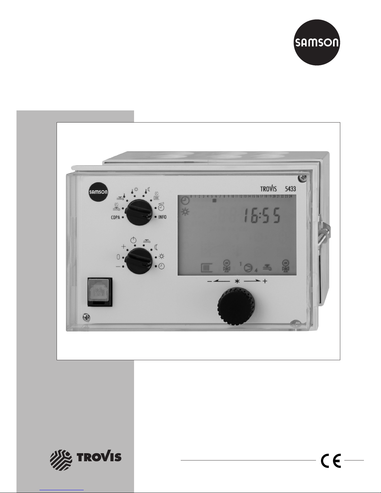
Automation System TROVIS 5400
Heating and District Heating Controller
TROVIS 5433
®
Electronics from SAMSON
Page 2
Disclaimer of liability
We are constantly developing our products and therefore, reserve the right to change the
product or the information contained in this document at any time without notice.
We do not assume any liability for the accuracy or completeness of these mounting and
operating instructions. Moreover, we do not guarantee that the buyer can use the product for
an intended purpose. SAMSON rejects any liability for claims by the buyer, especially
claims for compensation including lost profits or any other financial loss, except the damage
was caused intentionally or by gross negligence. If an essential term of the contract is
breached by negligence, SAMSON’s liability is limited to the foreseeable damage.
Safety instructions
4
The device may only be assembled, started up or operated by trained and
experienced personnel familiar with the product. Proper shipping and
appropriate storage are assumed.
4
The controller has been designed for use in electrical power systems. For
wiring and maintenance, you are required to observe the relevant safety
regulations.
2 EB 5433 EN
Disclaimer of liability
Page 3

Contents
1 Operation . . . . . . . . . . . . . . . . . . . . . . . . . . . . . . . 6
1.1 Operating elements. . . . . . . . . . . . . . . . . . . . . . . . . . . 6
1.1.1 Rotary pushbutton . . . . . . . . . . . . . . . . . . . . . . . . . . . 6
1.1.2 Rotary switches. . . . . . . . . . . . . . . . . . . . . . . . . . . . . 6
1.2 Operating modes. . . . . . . . . . . . . . . . . . . . . . . . . . . . 7
1.3 Display . . . . . . . . . . . . . . . . . . . . . . . . . . . . . . . . 8
1.4 Displaying data . . . . . . . . . . . . . . . . . . . . . . . . . . . . 9
1.5 Setting the controller time . . . . . . . . . . . . . . . . . . . . . . . 10
1.6 Setting the times-of-use . . . . . . . . . . . . . . . . . . . . . . . . 11
1.6.1 Setting public holidays . . . . . . . . . . . . . . . . . . . . . . . . 13
1.6.2 Setting vacation periods . . . . . . . . . . . . . . . . . . . . . . . . 15
1.7 Presetting temperature set points . . . . . . . . . . . . . . . . . . . . 17
2 Start-up. . . . . . . . . . . . . . . . . . . . . . . . . . . . . . . . 18
2.1 Setting the system code number . . . . . . . . . . . . . . . . . . . . 18
2.2 Activating and deactivating functions. . . . . . . . . . . . . . . . . . 19
2.3 Changing parameters . . . . . . . . . . . . . . . . . . . . . . . . . 21
2.4 Calibrating sensors . . . . . . . . . . . . . . . . . . . . . . . . . . 22
2.5 Resetting to default values . . . . . . . . . . . . . . . . . . . . . . . 24
3 Manual operation. . . . . . . . . . . . . . . . . . . . . . . . . . . 25
4 Systems. . . . . . . . . . . . . . . . . . . . . . . . . . . . . . . . 26
5 Functions of the heating circuit . . . . . . . . . . . . . . . . . . . . 36
5.1 Weather-compensated control . . . . . . . . . . . . . . . . . . . . . 36
5.1.1 Gradient characteristic . . . . . . . . . . . . . . . . . . . . . . . . 37
5.1.2 4-point characteristic . . . . . . . . . . . . . . . . . . . . . . . . . 38
5.2 Fixed set point control . . . . . . . . . . . . . . . . . . . . . . . . . 39
5.3 Drying of jointless floors . . . . . . . . . . . . . . . . . . . . . . . . 39
5.4 Outdoor temperature dependent deactivation. . . . . . . . . . . . . . 40
5.4.1 OT deactivation value rated operation . . . . . . . . . . . . . . . . . 40
5.4.2 OT deactivation value reduced operation. . . . . . . . . . . . . . . . 41
5.4.3 OT activation value rated operation . . . . . . . . . . . . . . . . . . 41
5.4.4 Summer mode . . . . . . . . . . . . . . . . . . . . . . . . . . . . 42
5.5 Delayed outdoor temperature adaptation. . . . . . . . . . . . . . . . 42
5.6 Remote operation . . . . . . . . . . . . . . . . . . . . . . . . . . . 43
5.6.1 Room panel. . . . . . . . . . . . . . . . . . . . . . . . . . . . . . 43
5.6.2 Floating switch . . . . . . . . . . . . . . . . . . . . . . . . . . . . 44
5.7 Optimization . . . . . . . . . . . . . . . . . . . . . . . . . . . . . 44
5.7.1 Advance heating depending on outdoor temperature . . . . . . . . . . 44
EB 5433 EN 3
Contents
Page 4

5.7.2 Optimization with room sensor . . . . . . . . . . . . . . . . . . . . 45
5.8 Flash adaptation . . . . . . . . . . . . . . . . . . . . . . . . . . . 46
5.9 Room temperature dependent control . . . . . . . . . . . . . . . . . 46
6 Functions of the DHW circuit. . . . . . . . . . . . . . . . . . . . . . 48
6.1 DHW heating in the storage tank system . . . . . . . . . . . . . . . . 48
6.2 DHW heating in the storage tank charging system . . . . . . . . . . . 50
6.3 DHW heating in the instantaneous water system . . . . . . . . . . . . 53
6.4 Intermediate heating operation . . . . . . . . . . . . . . . . . . . . 54
6.5 Parallel pump operation . . . . . . . . . . . . . . . . . . . . . . . . 54
6.6 Operation of circulation pump during storage tank charging . . . . . . 54
6.7 Priority operation . . . . . . . . . . . . . . . . . . . . . . . . . . . 55
6.7.1 Reverse control . . . . . . . . . . . . . . . . . . . . . . . . . . . . 55
6.7.2 Set-back operation . . . . . . . . . . . . . . . . . . . . . . . . . . 55
6.8 Forced charging of the DHW storage tank . . . . . . . . . . . . . . . 56
6.9 Thermal disinfection of the DHW storage tank . . . . . . . . . . . . . 56
6.10 Vacation periods and public holidays for DHW heating. . . . . . . . . 58
7 System-wide functions . . . . . . . . . . . . . . . . . . . . . . . . 59
7.1 Automatic summer time/winter time changeover . . . . . . . . . . . . 59
7.2 Frost protection . . . . . . . . . . . . . . . . . . . . . . . . . . . . 59
7.3 Forced operation of the pumps. . . . . . . . . . . . . . . . . . . . . 59
7.4 Return flow temperature limitation . . . . . . . . . . . . . . . . . . . 60
7.5 Condensate accumulation control . . . . . . . . . . . . . . . . . . . 61
7.6 Three-step control . . . . . . . . . . . . . . . . . . . . . . . . . . . 62
7.7 On/off control . . . . . . . . . . . . . . . . . . . . . . . . . . . . 62
7.8 Requesting/processing external demand . . . . . . . . . . . . . . . . 63
7.9 Locking the manual level. . . . . . . . . . . . . . . . . . . . . . . . 67
7.10 Locking the rotary switches . . . . . . . . . . . . . . . . . . . . . . 67
8 Operational faults . . . . . . . . . . . . . . . . . . . . . . . . . . 68
8.1 Error alarm list . . . . . . . . . . . . . . . . . . . . . . . . . . . . 68
8.2 Sensor failure . . . . . . . . . . . . . . . . . . . . . . . . . . . . . 68
8.3 Temperature monitoring . . . . . . . . . . . . . . . . . . . . . . . . 69
8.4 Collective alarm. . . . . . . . . . . . . . . . . . . . . . . . . . . . 69
9 Memory pen . . . . . . . . . . . . . . . . . . . . . . . . . . . . . 70
10 Installation . . . . . . . . . . . . . . . . . . . . . . . . . . . . . . 71
11 Electrical connection. . . . . . . . . . . . . . . . . . . . . . . . . . 73
12 Appendix. . . . . . . . . . . . . . . . . . . . . . . . . . . . . . . 76
4 EB 5433 EN
Contents
Page 5

12.1 Function block lists . . . . . . . . . . . . . . . . . . . . . . . . . . 76
12.2 Parameter lists . . . . . . . . . . . . . . . . . . . . . . . . . . . . 83
12.3 Sensor resistance tables . . . . . . . . . . . . . . . . . . . . . . . . 90
12.4 Technical data . . . . . . . . . . . . . . . . . . . . . . . . . . . . 91
12.5 Customer data . . . . . . . . . . . . . . . . . . . . . . . . . . . . 92
Index . . . . . . . . . . . . . . . . . . . . . . . . . . . . . . . . . 97
Abbreviations. . . . . . . . . . . . . . . . . . . . . . . . . . . . . 99
EB 5433 EN 5
Contents
Page 6

1 Operation
The controller is ready for use with the temperatures and operating schedules preset by the
manufacturer.
On start-up, the current time and date need to be adjusted at the controller (–> section 1.5).
1.1 Operating elements
The operating controls are located in the front panel of the controller and protected by a
Plexiglas door with an integrated quick guide.
1.1.1 Rotary pushbutton
Rotary pushbutton
Turn q:
Display, select parameters and function blocks
Press :
Confirm adjusted selection or settings
1.1.2 Rotary switches
Rotary switch for “Configuration and parameterization“
COPA Switch to configuration and parameter level
Times-of-use for DHW circulation pump
DHW temperature set point
Day set point (rated room temperature)
Night set point (reduced room temperature)
Times-of-use for heating
Controller time: setting the current time, date and year
INFO Switch to information level
(view measured values and their set points/limit values)
6 EB 5433 EN
Operation
*
Page 7

Rotary switch for “Operating modes“
– Manual operation: valve closes
0 Manual operation: valve stationary
+ Manual operation: valve opens
Control operation deactivated, frost protection only
DHW heating active, heating switched off
Night mode (reduced operation)
Day mode (rated operation)
Automatic mode (operation according to time schedule)
1.2 Operating modes
Day mode (rated operation)
Regardless of the programmed times-of-use and summer mode, the controller uses the set
points relevant for rated operation.
The
DHW temperature set point
remains constantly active in system Anl 6.
Night mode (reduced operation)
Regardless of the programmed times-of-use, the controller uses the set points relevant for reduced operation.
The
Sustained DHW temperature
remains constantly active in system Anl 6.
Automatic mode
During the programmed times-of-use, the controller works in rated operation. Outside these
times-of-use, the controller is in reduced operation, unless control operation is deactivated
depending on the outdoor temperature. The controller switches automatically between both
operating modes.
Manual operation – 0 +
Valves and pumps can be controlled manually (–> section 3).
The default setting of the circulation pump is permanent operation.
EB 5433 EN 7
Operation
Page 8
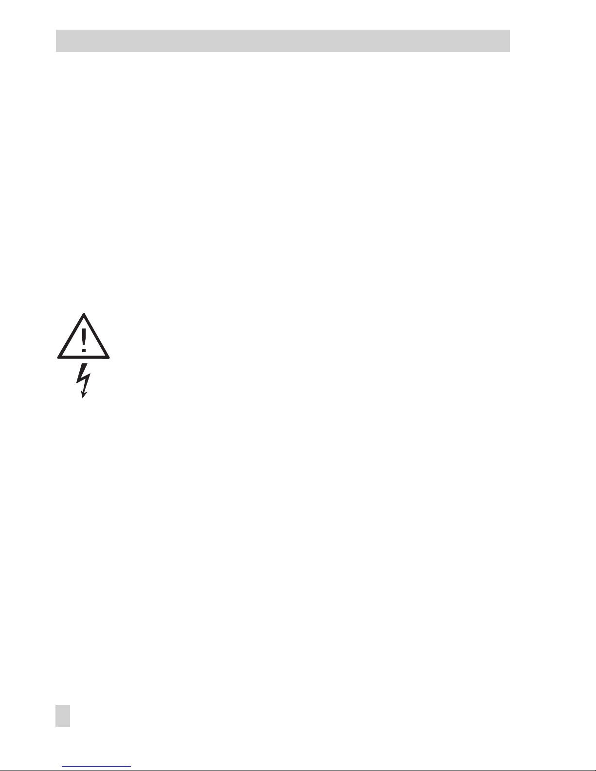
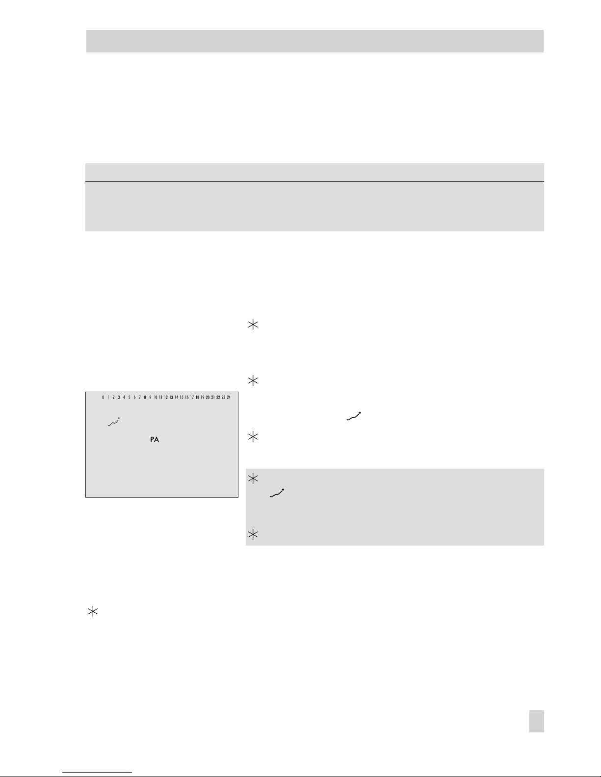
1.3 Display
During operation, the display indicates the current time as well as information about the op
eration of the controller. The days of the week are represented by black squares below the
row of numbers at the top of the display (1 = Monday, 2 = Tuesday, and shown here, 7 =
Sunday). Icons indicate the operating status of the controller.
The controller status can be displayed in operating level (–> section 1.4).
8 EB 5433 EN
Operation
102435
M
1
2
3
4
7681091112131514 16 1817 19 20 2221 23 24
M
9
8
7
6
5
4
3
2
1
10 11 12 13 14
Fig. 1 · Icons
1 Automatic mode
2 Public holidays
3 Day mode
(rated operation)
4 Vacation mode
5 Night mode
(reduced operation)
6 Summer mode
7 Frost protection
8 Manual operation
9 Operational fault
10 Heating circuit demand
11 Valve heating circuit
OPEN (left arrow)
CLOSED (right arrow)
12 Pump operation
1 Heating circul. pump UP
2 Exchanger charging
pump TLP
3 Storage charg. pump SLP
4 Circulation pump ZP
13 DHW demand
14 Valve DHW circuit
OPEN (left arrow)
CLOSED (right arrow)
Page 9

1.4 Displaying data
The time and temperature values of connected sensors and their set points can be retrieved
and displayed in the info level.
Proceed as follows:
Turn rotary switch “Configuration and parameterization“ to INFO.
Display shows: time _ _:_ _
The black squares below the row of numbers at the top of the display in this case repre
-
sent the times-of-use.
q
Depending on the configuration of the controller, different data points are displayed in
info level.
Room temperature, RS
Outdoor temperature, AS
/ Temperature at flow sensor VS1, heating circuit/primary exchanger circuit
Temperature at return flow sensor RüS
/ Temperature at flow sensor VS2, DHW circuit (Anl 3 to 5)
, Temperature at storage sensor (Anl 2 to 4)
Temperature at return flow sensor RüS_TW (Anl 5)
Compare the set point/limit temperature and the actual temperature.
EB 5433 EN 9
Operation
Page 10

1.5 Setting the controller time
The current time and date need to be set immediately after start-up or after a power failure
lasting more than 24 hours. This is the case when the time blinks on the display.
Proceed as follows:
Turn rotary switch “Configuration and
parameterization“ to data point “Controller time“.
Display shows: time
Activate editing mode for controller time.
blinks.
q
Edit time.
Confirm time.
Display shows: date (day.month)
The individual week days which are represented by
black squares below the row of numbers can be read
off at the top of the display:
1 = Monday, 2 = Tuesday, ..., 5 = Friday (shown here)
Activate editing mode for date.
blinks.
q
Edit date.
Confirm date.
Display shows: year
Activate editing mode for year.
blinks.
q
Edit year.
Confirm year.
Display shows: time
Return rotary switch “Configuration and
parameterization“ to INFO.
Display shows: time
10 EB 5433 EN
Operation
Page 11

1.6 Setting the times-of-use
Three times-of-use can be set for each day of the week.
If a time-of-use is not required, its start and stop times must be set to identical times.
The times-of-use for heating and the DHW circulation pump are set using the top rotary
switch:
Times-of-use Position
Heating
DHW circulation pump
Parameters
WE* Rotary switch / Range of values
Period/day 1 1, 2, 3, 4, 5, 6, 7 with 1-7 = every day,
1 = Monday, 2 = Tuesday, ..., 7 = Sunday
Start first time-of-use 7:00 0:00 h to 24:00 h; in steps of 30 minutes
Stop first time-of-use 22:00 0:00 h to 24:00 h; in steps of 30 minutes
Start second time-of-use 22:00 0:00 h to 24:00 h; in steps of 30 minutes
Stop second time-of-use 22:00 0:00 h to 24:00 h; in steps of 30 minutes
Start third time-of-use 22:00 0:00 h to 24:00 h; in steps of 30 minutes
Stop third time-of-use 22:00 0:00 h to 24:00 h; in steps of 30 minutes
*Default setting (WE) valid for heating (switch position )
Note!
The times-of-use for DHW heating are set in parameter level PA2 similar to the times-of-use
for heating and the DHW circulation pump.
EB 5433 EN 11
Operation
Page 12
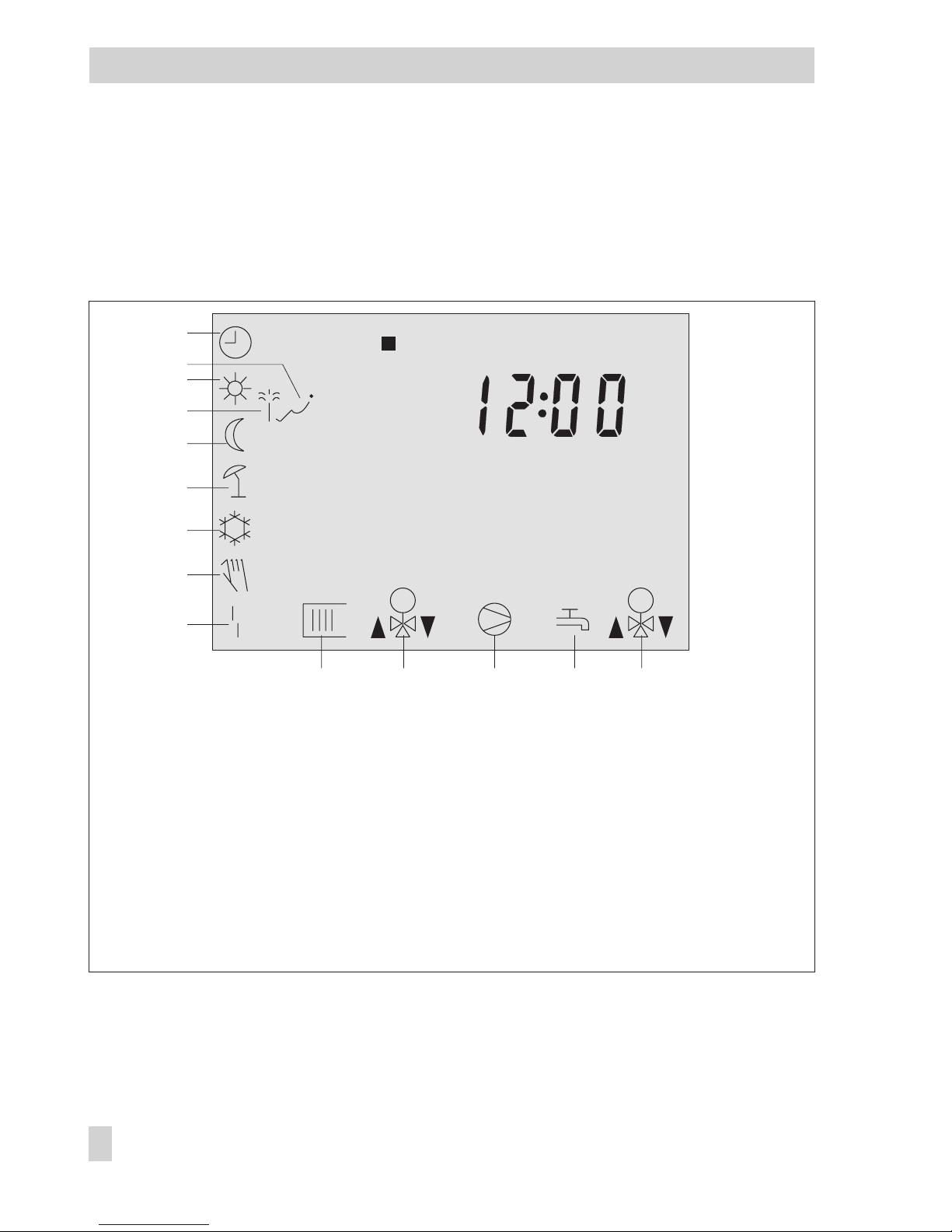
Proceed as follows: Turn rotary switch “Configuration and
parameterization“ to “Times-of-use”.
Display shows:
1
q
Select period/day for times-of-use:
1 = Monday, 2 = Tuesday , ..., 7 = Sunday,
1-7 = daily
Activate editing mode for period/day.
Display shows:
1*, START
* The display 1 (2, 3) indicates the first (second, third)
time-of-use.
Activate editing mode for start time.
and blink.
q
Edit start time (steps of 30 minutes).
Confirm start time.
Display shows:
STOP
q
Edit stop time (steps of 30 minutes).
Confirm stop time.
Display shows:
2, START
The second and third time-of use are set similar to the
first one.
q
Select
End
.
Exit active data point “Period/day“.
To set the times-of-use for additional days, repeat the instructions in the fields highlighted in
gray.
Return rotary switch “Configuration and parameterization“ to INFO.
Display shows: time
Note!
Do not use the
1–7
menu to check the adjusted times-of-use as only the times-of-use for
Monday are displayed under this data point, which are then adopted for the whole week.
12 EB 5433 EN
Operation
Page 13
1.6.1 Setting public holidays
On public holidays, the times-of-use specified for Sunday apply. A maximum of 20 public
holidays may be entered.
Parameter
WE Level / Range of values
Public holidays – PA-SYS / 01.01 to 31.12 (1 Jan to 31 Dec)
Adopt public holidays and
vacations for DHW
0 CO2 -> F07 - 1
Proceed as follows:
Turn rotary switch “Configuration and
parameterization“ to COPA.
Display shows:
0,NR
blinks.
q
Set valid key number.
Confirm key number.
Display shows:
PA 1
q
Select parameter level PA-SYS.
Open parameter level PA-SYS.
q
Select “Public holidays“.
Display shows:
Open “Public holidays“.
q
If applicable, select
– –.– –
.
Activate editing mode for public holiday.
blinks.
q
Edit public holiday.
Confirm public holiday.
To enter additional public holidays, re-select
– – – –
and repeat the steps in the fields high
-
lighted in gray.
q
Select
End
.
Exit parameter level.
Display shows: CO1
Return rotary switch “Configuration and parameterization“ to INFO.
Display shows: time
EB 5433 EN 13
Operation
Page 14

Note!
Public holidays that are not assigned to a specific date should be deleted by the end of the
year so that they are not carried on into the following year.
Deleting a public holiday:
q
Under “Public holidays“, select the holiday you wish to delete.
Confirm selection.
q
Select
– –.– –
(display – –.– – is adjustable between 31.12 and 01.01).
Delete public holiday.
14 EB 5433 EN
Operation
Page 15

1.6.2 Setting vacation periods
During vacation periods, the heating constantly remains in reduced operating mode. The
DHW heating is monitored for frost protection, if necessary. A maximum of 10 vacation pe
-
riods can be entered.
Parameter
WE Level / Range of values
Vacation period (START, STOP) – PA-SYS / 01.01 to 31.12 (1 Jan to 31 Dec)
Adopt public holidays and
vacations for DHW
0 CO2 -> F07 - 1
Proceed as follows:
Turn rotary switch “Configuration and
parameterization“ to COPA.
Display shows:
0,NR
blinks.
q
Set valid key number.
Confirm key number.
Display shows:
PA 1
q
Select parameter level PA-SYS.
Open parameter level PA-SYS.
q
Select “Vacation periods“.
Display shows:
Open “Vacation periods“
Display shows:
START
q
If applicable, select
– –.– –
.
Activate editing mode for start date of vacation period.
START
and blink.
q
Edit start date of vacation period.
Confirm start date of vacation period.
Display shows:
STOP, start date of vacation period
q
Edit end of vacation period.
Confirm end of vacation period.
To enter additional vacation periods, re-select
– –.– –
and repeat the steps in the fields
highlighted in gray.
EB 5433 EN 15
Operation
Page 16

q
Select
End
.
Exit parameter level.
Display shows: CO1
Return rotary switch “Configuration and parameterization“ to INFO.
Display shows: time
Note!
Vacation periods should be deleted by the end of the year so that they are not carried on
into the following year.
Deleting vacation periods:
q
Under “Vacation periods“, select the start date of the period you wish to delete.
Confirm selection.
q
Select
– –.– –
(display – –.– – is adjustable between 31.12 and 01.01).
Delete vacation period.
16 EB 5433 EN
Operation
Page 17

1.7 Presetting temperature set points
For the heating circuit, the desired room temperatures during the day (
Day set point
) and
during the night (
Night set point
) can be preset.
In the DHW circuit, the temperature you wish the domestic hot water to be heated to can be
adjusted.
The temperature set points are adjusted using the top rotary switch:
Desired temperature set point Position
Day set point
Night set point
DHW temperature set point
Parameters
WE Rotary switch / Range of values
Day set point 20 °C 10 to 40 °C
Night set point 15 °C 10 to 40 °C
DHW temperature set point 55 °C Min. to max. DHW temperature
Proceed as follows:
Turn rotary switch “Configuration and parameterization“ to “Set point temperature“.
Display shows: temperature value
Activate editing mode for set point temperature.
Display blinks.
q
Edit set point temperature.
Confirm set point temperature.
Return rotary switch “Configuration and parameterization“ to INFO.
Display shows: time
EB 5433 EN 17
Operation
Page 18

2 Start-up
The modifications of the controller configuration and parameter settings described in this sec
-
tion can only be carried out after the valid key number has been entered.
The valid key number for initial start-up can be found on page 96. To avoid unauthorized
use of the key number, remove the page or make the key number unreadable.
2.1 Setting the system code number
Six different hydraulic schemes are available. Each system configuration is represented by a
system code number. The different schemes are dealt with in section 4. Available controller
functions are described in sections 5, 6 and 7.
Changing the system code number resets previously adjusted function blocks to their default
values. Function block parameters and parameter level settings remain unchanged.
The system code number is set in the configuration level.
Proceed as follows:
Turn rotary switch “Configuration and parameterization“ to COPA.
Display shows:
0,NR
blinks.
q
Set valid key number.
Confirm key number.
Display shows:
PA 1
q
Select
Anl
.
View current system code number.
Activate editing mode for system code number.
Anl
blinks.
q
Set system code number.
Confirm system code number.
Display shows:
End
Exit data point “System code number“.
Return rotary switch “Configuration and parameterization“ to INFO. Display shows: time
18 EB 5433 EN
Start-up
Page 19

2.2 Activating and deactivating functions
A function is activated via the associated function block. The numbers 0 to 24 in the top row
of the display represent the respective function block numbers. When a configuration level is
opened, the activated function blocks are indicated by a black square on the right-hand side
below the function block number. For more details on function blocks, refer to section 12.1.
The functions are grouped by topics:
4
CO1: Heating circuit
4
CO2: DHW heating
4
CO-SYS: System-wide
Proceed as follows:
Turn rotary switch “Configuration and parameterization“ to COPA.
Display shows:
0,NR
blinks.
q
Set valid key number.
Confirm key number.
Display shows:
PA 1
q
Select configuration level.
Open configuration level.
q
Select function block.
Activated function blocks are marked by “- 1“.
Deactivated function blocks are marked by “- 0“.
Activate editing mode for function block.
F__
blinks.
q
Activate function block.
Display shows:
F__ - 1
Or:
q
Deactivate function block.
Display shows:
F__ - 0
EB 5433 EN 19
Start-up
Page 20

Confirm settings.
If the function block is not closed, further function block parameters can be adjusted.
Proceed as follows:
1. Open data point.
2. Make desired changes and confirm.
3. If applicable, the next function block parameter is displayed.
When all function block parameters have been adjusted, select
End
and confirm.
The active function block is closed.
An active function block is represented by a black square on the right-hand side below
the function block number.
To adjust additional function blocks, repeat the steps in the fields highlighted in gray.
q
Select
End
.
Exit configuration level.
Return rotary switch “Configuration and parameterization“ to INFO. Display shows: time
20 EB 5433 EN
Start-up
Page 21

2.3 Changing parameters
Depending on the adjusted system code number and the activated functions, not all parame
ters listed in the parameter list in the Appendix (–> section 12.2) might be available.
The parameters are grouped by topics:
4
PA1: Heating circuit
4
PA2: DHW heating
4
PA-SYS: Public holidays and vacation periods
Proceed as follows:
Turn rotary switch “Configuration and parameterization“ to COPA.
Display shows:
0,NR
blinks.
q
Set valid key number.
Confirm key number.
Display shows:
PA 1
q
Select parameter level.
Open parameter level.
q
Select parameter.
Activate editing mode for parameter.
q
Set parameter.
Confirm parameter.
To adjust additional parameters, repeat the steps in the fields highlighted in gray.
q
Select
End
.
Exit parameter level.
Return rotary switch “Configuration and parameterization“ to INFO. Display shows: time
EB 5433 EN 21
Start-up
Page 22

2.4 Calibrating sensors
The connected sensors are calibrated in configuration level CO-SYS.
The following applies:
4
CO-SYS -> F02 - 1: Pt 1000 sensors (default)
4
CO-SYS -> F02 - 0: PTC sensors
The resistance values of the sensors can be found on page 91.
If the temperature values displayed on the controller differ from the actual temperatures, the
measured values of all connected sensors can be changed or readjusted. To calibrate a sen
sor, the currently displayed sensor value must be changed to match a temperature (reference
value) measured directly at the point of measurement.
Activate the sensor calibration in CO-SYS over function block F08.
An incorrect sensor calibration can be deleted by setting F08 - 0.
Proceed as follows:
Turn rotary switch “Configuration and parameterization“ to COPA.
Display shows:
0,NR
blinks.
q Set valid key number.
Confirm key number.
Display shows:
PA 1
q
Select configuration level CO-SYS.
Open configuration level CO-SYS.
q
Select function block F08.
Activate editing mode for function block F08.
q
Activate function block F08 (F08 - 1).
Confirm function block settings.
q
Select sensor icon:
Room sensor RS
Outdoor sensor AS
22 EB 5433 EN
Start-up
Page 23

Flow sensor VS1
Return flow sensor RüF
/ Flow sensor VS2/VS1 (system Anl 6)
Storage sensor SS1
Storage sensor SS2
Return flow sensor RüS_TW
Activate editing mode for measured value.
q
Correct measured value.
Read the actual temperature directly from the thermometer at the point of measurement
and enter this value as the reference temperature.
Confirm corrected measured value.
Additional sensors are calibrated similarly.
q
Select
End
.
Exit function block F08.
q
Select
End
.
Exit configuration level CO-SYS.
Return rotary switch “Configuration and parameterization“ to INFO. Display shows: time
EB 5433 EN 23
Start-up
Page 24

2.5 Resetting to default values
All parameters as well as the function block parameters can be reset to their default
settings (WE).
Proceed as follows:
Turn rotary switch “Configuration and parameterization“ to COPA.
Display shows:
0,NR
blinks.
q
Set valid key number.
Confirm key number.
q
Select configuration level CO-SYS.
Open configuration level CO-SYS.
q
Select function block F09.
Activate editing mode for function block F09.
q
Set F09 - 1.
Reset parameters to their default values.
q
Select
End
.
Exit configuration level CO-SYS.
Return rotary switch “Configuration and parameterization“ to INFO. Display shows: time
24 EB 5433 EN
Start-up
Page 25

3 Manual operation
Switch to manual operating mode to access all outputs (see wiring diagram in section 11).
When manual operation is activated using the rotary switch for “Operating modes“, the ro
tary switch “Configuration and parameterization“ should be in position INFO, otherwise the
pump level cannot be accessed over the rotary pushbutton.
Proceed as follows:
Turn rotary switch “Configuration and parameterization“ to INFO.
Turn “Operating modes“ switch to +, 0 or –.
Display shows:
q
Select pump level PU.
Open pump level PU.
Display shows: PU 1 - 0 / PU 1 - 1: heating circulation pump switched off/on
q
Select pump:
PU 1: Heating circulation pump UP
PU 2: Exchanger charging pump TLP (ZP / Anl 5)
PU 3: Storage tank charging pump SLP (DHW valve opens / Anl 5)
PU 4: Circulation pump ZP (DHW valve closes / Anl 5)
PU 5: Binary output BA (TLP / Anl 5)
Confirm selection. PU blinks.
q
Activate/ deactivate output:
PU _ - 0: deactivate pump/binary output
PU _ - 1: activate pump/binary output
Confirm edited settings.
The modified values remain active as long as the controller is in the manual mode.
q
Select
End
.
Exit pump level PU.
Turn bottom rotary switch to the desired operating mode.
Note!
Setting the rotary switch to position “Manual operation“ (+ 0 –) also sets PU1 - 1 (not in sys
-
tem Anl 6). All other outputs are deactivated.
EB 5433 EN 25
Manual operation
Page 26
BE
BA
AE
RK
RüS VS1UPHK RS
BE
BA
AE
RK
VS1UP RüSHK RS
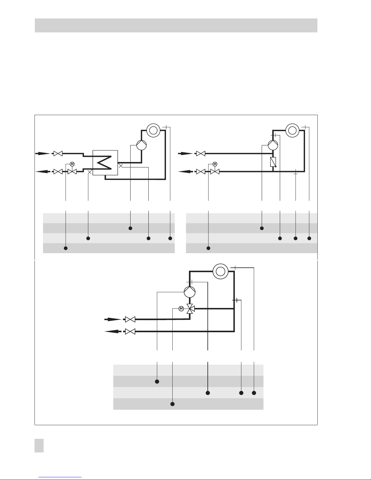
4 Systems
Six different hydraulic schemes are available. The systems can be configured both as pri
mary and secondary systems. The fundamental hydraulic difference between a primary and
a secondary system (heat exchanger in the heating/DHW circuit replaced by a mixing valve)
is illustrated in Fig. 2. The controller settings do not have to be changed.
26 EB 5433 EN
Systems
Primary system, indirect Primary system, direct
BE
BA
AE
RK
RüSVS1UP HK RS
Fig. 2 · Converting a primary system into a secondary system
Secondary system
Page 27
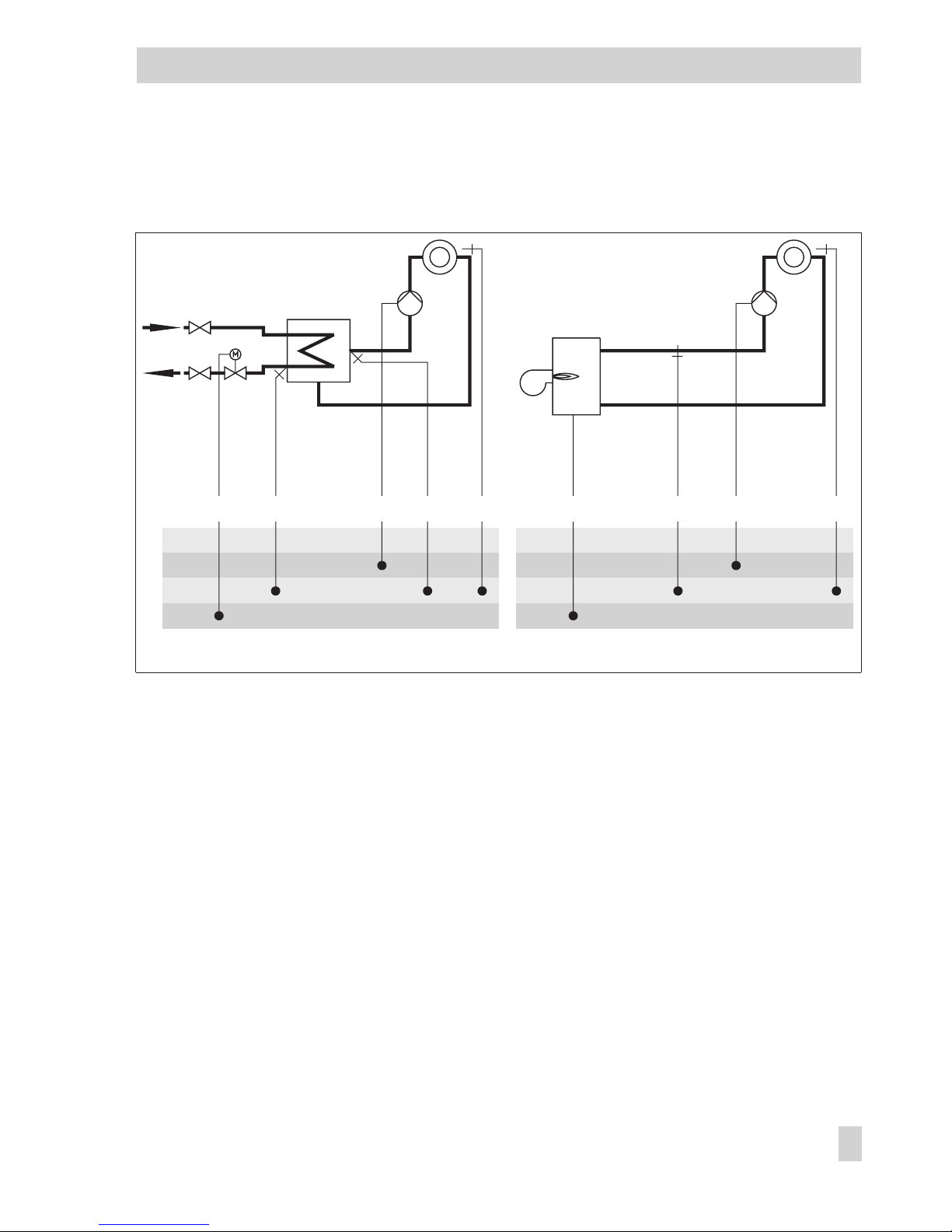
Boiler systems:
Based on the systems Anl 1 to Anl 3, one-stage boiler systems can be set up.
The boiler can be controlled by an on/off output (CO-SYS -> F05 - 0).
EB 5433 EN 27
Systems
BE
BA
AE
RK
RüS VS1UPHK RS
BE
BA
AE
RK
UPHK_2-Pkt RSVS1
Fig. 3 · Schematics of a boiler system
Boiler
1-stage
HK Heating circuit
RüS Return flow sensor
UP Circulation pump
VS Flow sensor
RS Room sensor
BE Binary input
BA Binary output
AE Analog input
RK Control loop
Page 28
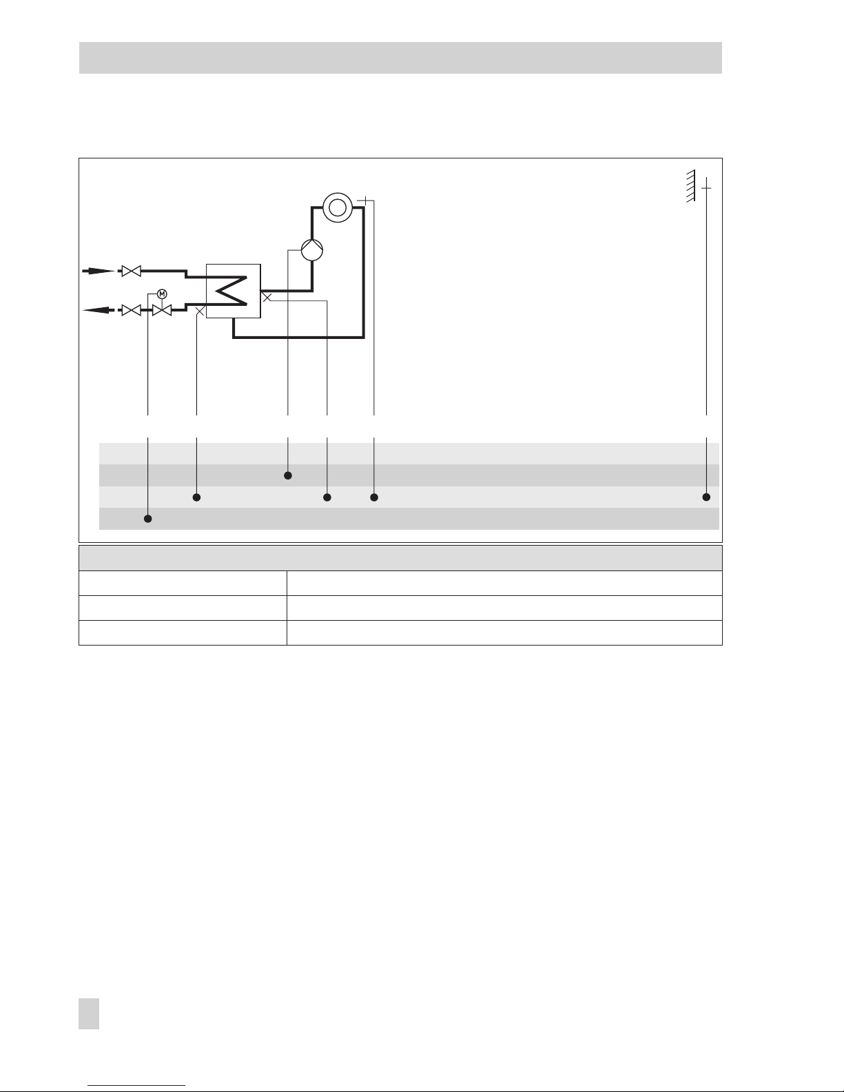
System Anl 1
Default values
CO1 -> F01 - 0 (without RS)
CO1 -> F07 - 1 (with AS)
CO-SYS -> F01 - 1 (with RüS)
28 EB 5433 EN
Systems
BE
BA
AE
RK
ASRüS VS1UPHK RS
Page 29
System Anl 2
Default values
CO1 -> F01 - 0 (without RS)
CO1 -> F07 - 1 (with AS)
CO2 -> F01 - 1 (with SS1)
CO2 -> F02 - 0 (without SS2)
CO-SYS -> F01 - 1 (with RüS)
EB 5433 EN 29
Systems
HK Heating circuit
RüS Return flow sensor
UP Circulation pump
VS Flow sensor
RS Room sensor
SLP Storage tank charging pump
WW Hot water
KW Cold water
ZP Circulation pump
SS Storage tank sensor
AS Outdoor sensor
BE Binary input
BA Binary output
AE Analog input
RK Control loop
BE
BA
AE
RK
WW
KW
ASZP
RüS VS1
UP
SS1
HK
RS
SLP
Page 30
System Anl 2, settings deviating from default settings
Settings deviating from default values
CO2 -> F10 - 0 (priority for DHW heating)
CO2 -> F06 - 1, option 2 (control of changeover valve and UP)
30 EB 5433 EN
Systems
BE
BA
AE
RK
WW
KW
ASZP
RüS VS1 SS1
HK
RS
UP SLP
Page 31

System Anl 3
Default values
CO1 -> F01 - 0 (without RS)
CO1 -> F07 - 1 (with AS)
CO2 -> F01 - 1 (with SS1)
CO2 -> F02 - 1 (with SS2)
CO2 -> F03 - 0 (without VS2)
CO-SYS -> F01 - 1 (with RüS)
EB 5433 EN 31
Systems
BE
BA
AE
RK
WW
KW
AS
SS2
ZP
RüS VS1 VS2
UP
SS1
HK
RS SLP
TLP
Page 32

System Anl 4
Default values
CO1 -> F01 - 0 (without RS)
CO1 -> F07 - 1 (with AS)
CO2 -> F01 - 1 (with SS1)
CO2 -> F02 - 1 (with SS2)
CO2 -> F09 - 0 (without VS2)
CO-SYS -> F01 - 1 (with RüS)
Note!
The charging temperature is regulated by a self-operated regulator (ROH).
32 EB 5433 EN
Systems
ROH
BE
BA
AE
RK
WW
KW
AS
SS2
ZP SLP
RüS VS1 VS2
UP
SS1
HK
RS
Page 33

System Anl 5
Default values
CO1 -> F01 - 0 (without RS)
CO1 -> F07 - 1 (with AS)
CO2 -> F11 - 1 (storage system uses three-step control)
CO2 -> F12 - 1 (with RüS_TW)
CO-SYS -> F01 - 1 (with RüS)
Using setting CO2 -> F11 - 0, a temperature valve is configured instead of the three-step
control valve DHW.
A demand with CO-SYS -> F11 - 1 is exclusively processed in the heating circuit.
EB 5433 EN 33
Systems
BE
BA
AE
RK
WW
KW
ASZP
RüSHK VS1RüS_TW
UP
VS2
TW
RS
Page 34

System Anl 5, settings deviating from default settings
Settings deviating from default values
CO2 -> F14 - 1 (system with instantaneous water heater including
hydraulic pressure switch)
Note!
A Pt 1000 sensor must always be used for the sensor VF2 regardless of the configuration of
the other sensors.
34 EB 5433 EN
Systems
BE
BA
AE
RK
WW
KW
ASFDS ZP TLP
RüSHK VS1
UP
VS2
TW
RS
Page 35

System Anl 6
Default values
CO2 -> F01 - 1 (with SS1)
CO2 -> F02 - 1 (with SS2)
CO2 -> F03 - 0 (without VS2)
CO2 -> F17 - 0 (without ZS)
CO-SYS -> F01 - 1 (with RüS)
EB 5433 EN 35
Systems
BE
BA
AE
RK
WW
KW
SS2 ZP SLPVS2 ZS ZSTLP RÜSVS1 SS1HK
Page 36

5 Functions of the heating circuit
Which controller functions are available depends on the selected system code number.
5.1 Weather-compensated control
When weather-compensated control is used, the flow temperature is adjusted depending on
the outdoor temperature. The heating characteristic in the controller defines the flow temper
ature set point as a function of the outdoor temperature (–> Fig. 4). The outdoor temperature
required for weather-compensated control is either measured at the outdoor sensor or re
-
ceived as an 0 to 10 V signal.
Function
WE Configuration
Outdoor temperature t
A
1 CO1 -> F07 - 1
If you wish to alternatively receive the outdoor temperature as an 0 to 10 V signal, the fol
-
lowing additional configurations must be made:
Functions
WE Configuration
Outdoor temp. 0 to 10 V at input UE 0 CO1 -> F08 - 1
External demand, demand processing 0 CO-SYS -> F11- 0
36 EB 5433 EN
Functions of the heating circuit
20
30
0.2
2.4
2.62.93.2
2.2
2.0
1.8
1.6
1.4
1.2
1.0
0.8
0.4
0.6
40
50
60
70
80
90
100
110
120
130
t
VL
[˚C]
-20 [
˚
C]
t
A
-16-12-8-4048121620
Fig. 4 · Gradient characteristics
t
VL
Flow temperature
t
A
Outdoor temperature
Page 37

5.1.1 Gradient characteristic
Basically, the following rule applies: a decrease in the outdoor temperature causes the flow
temperature to increase in order to keep the the room temperature at a constant temperature.
By varying the parameters
Gradient
and
Level
, you can adapt the characteristic to your indi
-
vidual requirements:
The gradient needs to be increased if the room temperature
drops when it is cold outside
The gradient needs to be decreased if the room temperature rises when it is cold outside.
The level needs to be increased and the gradient decreased
if the room temperature drops when it is mild outside.
EB 5433 EN 37
Functions of the heating circuit
t
VL
t
A
[°C]
[°C]
20 0 –20
t
VL
t
A
[°C]
[°C]
20 0 –20
t
VL
t
A
[°C]
[°C]
20 0 –20
Page 38

The level needs to be decreased and the gradient increased
if the room temperature rises when it is mild outside.
Outside the times-of-use, reduced set points are used for control:
The reduced flow set point is calculated as the difference between the adjusted values for
Day set point
(rated room temperature) and
Night set point (reduced room temperature).
The parameters
Max. flow temperature
and
Min. flow temperature
mark the upper and lower
limits of the flow temperature. A separate gradient characteristic can be selected for the limi
-
tation of the return flow temperature.
Examples for adjusting the characteristic:
4
Old building, radiator design 90/70: Gradient approx. 1.8
4
New building, radiator design 70/55: Gradient approx. 1.4
4
New building, radiator design 55/45: Gradient approx. 1.0
4
Underfloor heating depending on installation: Gradient smaller than 0.5
Note!
Particularly for control operation without room sensor, the adjusted room temperatures for
day (Day set point) and night (Night set point) only become effective satisfactorily when the
heating characteristic has been adapted to the building/the heating surface layout.
Function
WE Configuration
Characteristic 0 CO1 -> F04 - 0
Parameters
WE Rotary switch / Range of values
Day set point 20 °C 10 to 40 °C
Night set point 15 °C 10 to 40 °C
Parameters
WE Parameter level / Range of values
Gradient, flow 1.8 PA1 / 0.2 to 3.2
Level, flow 0 °C PA1/ –30 to 30 °C
Min. flow temperature 20 °C PA1 / 0 °C to max. flow temperature
Max. flow temperature 90 °C PA1 / Min. flow temperature to 130 °C
38 EB 5433 EN
Functions of the heating circuit
t
VL
t
A
[°C]
[°C]
20 0 –20
Page 39

5.1.2 4-point characteristic
The 4-point characteristic allows you to define your own heating characteristic.
It is defined by 4 points for the
Outdoor temperature
, the
Flow temperature,
the
Reduced
flow temperature
and the
Return flow temperature
. The
Set-back difference
at points 2 and 3
indicates the value by which the flow temperature is reduced outside the times-of-use. The
parameters
Max. flow temperature
and
Min. flow temperature
mark the upper and lower
limits of the flow temperature.
Note!
The parameters
Day set point
and
Night set point
are no longer available when the 4-point
characteristic has been selected, provided no additional functions (e.g. Optimization or
Flash adaptation) have been selected.
Function
WE Configuration
Characteristic 0 CO1 -> F04 - 1
Parameters
WE Parameter level / Range of values
Outdoor
temperature
Point 1
Point 2
Point 3
Point 4
–15 °C
–5 °C
5°C
15 °C
PA1 / –30 to 50 °C
EB 5433 EN 39
Functions of the heating circuit
t
VLmax
t
VLmin
t
VL
100
90
80
70
60
50
40
30
20
10
[˚C]20 15 10 5 0 –5 –10 –15 –20
P1
P2
P3
P4
[˚C]
t
A
Fig. 5 · 4-point characteristic
P1to P4 Points 1 to 4
t
VL
Flow temperature
t
A
Outdoor temperature
...min Minimum t
VL
...max Maximum t
VL
----- Reduced flow temperature
Page 40

Parameters
WE Parameter level / Range of values
Flow temperature Point 1
Point 2
Point 3
Point 4
70 °C
55 °C
40 °C
25 °C
PA1 / 20 to 130 °C
Return flow temp. Points 1 to 4 65 °C PA1 / 20 to 90 °C
Set-back difference Points 2, 3 15 °C PA1 / 0 to 50 °C
Min. flow temperature 20 °C PA1 / 0 °C to max. flow temperature
Max. flow temperature 90 °C PA1 / Min. flow temperature to 130 °C
5.2 Fixed set point control
During the times-of-use, the flow temperature can be controlled according to a fixed set
point. Outside the times-of-use, the controller uses the reduced flow temperature.
Set the desired rated flow temperature as
Day set point
, and the reduced flow temperature
as
Night set point
.
Function
WE Configuration
Outdoor temperature t
A
1 CO1 -> F07 - 0
Parameters
WE Rotary switch / Range of values
Day set point 50 °C 0 to 130 °C
Night set point 30 °C 0 to 130 °C
5.3 Drying of jointless floors
The first heating up is performed with a flow temperature of 25 °C. In the course of 24
hours, this temperature is raised by the value entered in
Temperature rise
, i.e. the default set
-
ting causes the temperature to rise continuously to 30 °C within the first 24 hours. If the
Max
-
imum temperature
is reached, it is kept constant for the number of days entered in
Main
-
taining time for maximum temperature
. The
Temperature reduction
parameter determines the
downward ramp. If this parameter is set to 0, the maintaining phase runs straight into the
automatic mode.
By changing the setting
STOP 0toSTART 1,
the function is activated. The controller permits
no further change to the operating parameters of the function.
The course of the drying process can be monitored in the information level over the icon of
flow temperature display ( ) of the heating circuit:
40 EB 5433 EN
Functions of the heating circuit
Page 41

The digit behind START _ indicates in which operating
phase the drying of jointless floors is in:
4
1 = Temperature build-up phase
4
2 = Temperature maintaining phase
4
3 = Temperature reducing phase
The drying process has been successfully completed when
the additional icon in the flow temperature display goes out
after the last phase without an operating fault appearing.
Err 6
indicates that the flow tem
perature deviated from the set point by more than 5 °C for longer than 30 minutes which
leads to the drying process being canceled. While
Err 6
appears, a flow temperature of 25
°C is used. Any disconnection of the power supply automatically leads to the drying process
starting from the beginning again.
Note!
In the information level, an active drying function is indicated by the icon. In system code
numbers 2 and 3, storage charging is not performed while the drying of jointless floors is active, provided they do not serve to the frost protection of the storage tank.
After the drying function has been successfully completed, the function block CO1 -> F09
should not be deactivated if you want to trace back with which operating parameters the
drying process was carried out.
Function
WE Configuration
Drying of jointless floors 0
5.0 °C/24 h
45 °C
4 days
5.0 °C/24 h
STOP 0
CO1 -> F09 - 1
Temperature rise / 1.0 to 10.0 °C/24 h
Maximum temperature / 25 to 60 °C
Maintaining time for maximum temperature /
1 to 10 days
Temperature reduction / 0.0 to 10.0 °C/24 h
START 1
5.4 Outdoor temperature dependent deactivation
5.4.1 OT deactivation value rated operation
If the outdoor temperature exceeds the limit in
OT deactivation value rated operation
, the
heating circuit is put out of service immediately. The valve is closed and the pump is switched
off after the adjusted
Lag time of heating circulation pump
has elapsed. When the outdoor
EB 5433 EN 41
Functions of the heating circuit
Page 42

temperature falls below this value (less 0.5 °C hysteresis), heating operation is restarted im
-
mediately.
With the default settings, this means that, during the warm season, the system is switched off
at an outdoor temperature of 22 °C.
Parameters
WE Parameter level / Range of values
OT deactivation value rated operation 22 °C PA1 / 0 to 50 °C
Lag time of heating circulation pump 180 sec PA1 / 15 to 2400 sec
5.4.2 OT deactivation value reduced operation
If the outdoor temperature exceeds the limit value
OT deactivation value reduced operation
in
reduced operation, the heating circuit is put out of service immediately. The valve is closed and
the pump is switched off after the adjusted
Lag time of heating circulation pump
has elapsed.
When the outdoor temperature falls below this value, heating operation is restarted immedi
-
ately.
With the default settings, this means that, at night, the system is switched off at an outdoor
temperature of 15 °C to save energy. Nevertheless, remember that the system requires some
time in the morning to heat up the building (–> Advance heating depending on outdoor temperature, section 5.7.1).
Parameters
WE Parameter level / Range of values
OT deactivation value reduced operation 15 °C PA1 / OT activation value rated operation to 50 °C
Lag time of heating circulation pump 180 sec PA1 / 15 to 2400 sec
5.4.3 OT activation value rated operation
If the heating circuit is in reduced operation (automatic operating mode), the circuit is auto
matically transferred to rated operation when the outdoor temperature falls below the limit
value
OT activation value rated operation
. Reduced operation is restarted when the limit
value is exceeded.
This function is activated at very low temperatures to avoid that the building cools down ex
cessively outside the times-of-use when low outdoor temperatures occur.
Parameter
WE Parameter level / Range of values
OT activation value rated operation –15 °C PA1 / –30 °C to OT activation value reduced
operation
42 EB 5433 EN
Functions of the heating circuit
Page 43

5.4.4 Summer mode
Summer mode is activated depending on the mean daytime temperature (measured between
7.00 h and 22.00 h) during the desired period.
If the mean daytime temperature exceeds the
OT limit value summer mode
on n successive
days, summer mode is activated on the following day. This means that the heating is
switched off. If the mean daytime temperature remains below the
OT limit value summer
mode
on m successive days, summer mode is deactivated on the following day.
Summer mode only becomes effective when the controller is in automatic mode ( ).
Functions
WE Configuration
Summer mode 0
01.06
2
30.09
1
18 °C
CO1 -> F06 - 1
Start summer mode / 01.01 to 31.12 (1 Jan to 31 Dec)
No. of days until activation / 1 to 3
Stop summer mode / 01.01 to 31.12
No. of days until deactivation / 1 to 3
OT limit value summer mode / 0 to 50 °C
Outdoor temperature t
A
1 CO1 -> F07 - 1
5.5 Delayed outdoor temperature adaptation
The calculated outdoor temperature is used to determine the flow temperature set point. The
heat response is delayed when the outdoor temperature either decreases or increases and
decreases. If the outdoor temperature varies by, for example, 12 °C within a very short pe
-
riod of time, the calculated outdoor temperature is adapted to the actual outdoor tempera
-
ture in small steps. Assuming a
Delay
of 3 °C/h, the adaptation would take
th
C
Ch
12
3
4
/
.
Note!
The delayed outdoor temperature adaptation helps avoid unnecessary overloads of central
heating stations in combination with either overheated buildings occurring, for example, due
to warm winds, or temporarily insufficient heating due to the outdoor sensor being exposed
to direct sunshine. In the info level, the calculated outdoor temperature can be viewed by
pressing the rotary switch while the outdoor temperature is displayed.
EB 5433 EN 43
Functions of the heating circuit
Page 44

Functions
WE Configuration
Delayed outdoor temperature
adaptation
0
3 °C/h
CO1 -> F05 - 1 (1,2)
1
When outdoor temperature tAdecreases
2
When outdoor temp. tAdecreases and increases
Delay / 1 to 6 °C/h
Outdoor temperature t
A
1 CO1 -> F07 - 1
5.6 Remote operation
5.6.1 Room panel
Apart from measuring the room temperature, the Type 5244 Room Panel (PTC sensor) and
the Type 5257-5 Room Panel (Pt 1000 sensor) allow you to influence the control process as
follows:
4
Selection of the operating mode:
– Automatic mode
– Day mode
– Night mode
4
Set point correction: during rated operation, the room temperature set point can be in
-
creased or reduced by up to 5 °C using a continuously adjustable rotary knob.
44 EB 5433 EN
Functions of the heating circuit
13
14
15
12
11
10
9
8
7
6
312
Fig. 6 · Terminal assignment Types 5244/5257-5 Room Panels – TROVIS 5433 Controller
Type 5244, 5257-5
Type 5433
Page 45

When the room sensor is activated and the remote room controller (room panel) is connected
and activated, the measured room temperature is displayed. Nevertheless, it is not used for
control unless the Optimization or Flash adaptation functions have been activated.
Function
WE Configuration
Room sensor RS 0
CO1 -> F01 - 1, option: 1
Note!
The
Day set point
adjusted via the rotary switch remains unaffected by set point corrections
performed over the room panel. Only the calculated flow temperature set point or the room
temperature set point (for flash adaptation) are adjusted accordingly.
5.6.2 Floating switch
The heating circuit can be switched to night mode by closing the switching contact if a floating switch is connected to input RS.
Function
WE Configuration
Room sensor RS 0 CO1 -> F01 - 0
5.7 Optimization
5.7.1 Advance heating depending on outdoor temperature
The controller activates rated operation of the heating system before the time-of-use starts de
-
pending on the outdoor temperature. The
Advance heating time
refers to an outdoor temper
ature of –12 °C. In case of higher outdoor temperatures, the advance heating time is
reduced.
This means, the colder it is outside, the earlier the night set-back is terminated to ensure that
the desired room temperature
Day set point
has been reached at the beginning of the
time-of-use, if possible.
Functions
WE Configuration
Optimization 0
120 min
CO1 -> F02 - 1, option:1
Advance heating time / 0 to 360 min
Outdoor temperature t
A
1 CO1 -> F07 - 1
EB 5433 EN 45
Functions of the heating circuit
Page 46

5.7.2 Optimization with room sensor
The following two functions are only appropriate when the room containing the room sensor
(reference room) has a heating characteristic similar to the rest of the building.
No thermostatic valves should be mounted on the radiators in the reference room.
Depending on the activation conditions, two optimizing modes are available:
4
Advance heating depending on outdoor temp., deactivation depending on room temp.
The controller activates rated operation of the heating system before the time-of-use starts
depending on the outdoor temperature. The
Advance heating time
refers to an outdoor
temperature of –12 °C. In case of higher outdoor temperatures, the advance heating time
is reduced (-> section 5.7.1).
4
Advance heating and deactivation depending on room temperature
Depending on the building characteristics, the controller determines and adapts the re
-
quired advance heating time (max. 6 hours) to ensure that the desired
Day set point
(rated room temperature) has been reached in the reference room when the time-of-use
starts. During the advance heating period, the controller heats with the max. flow temperature. As soon as the
Day set point
has been reached, weather-compensated control is
activated.
Depending on the room sensor, the controller switches off the heating system up to 2 hours
before the time-of-use ends. The controller chooses the deactivation time such that the room
temperature does not drop significantly below the desired value until the time-of-use ends.
During the advance heating period and the premature deactivation of the heating system,
the icons or blink on the display. Outside the times-of-use, the controller monitors the
Night set point
(reduced room temperature). When the temperature falls below the night set
point, the controller heats with the max. flow temperature until the measured room tempera
-
ture exceeds the adjusted value by 1 °C.
Note!
Direct sunshine can cause the room temperature to increase and thus result in the premature
deactivation of the heating system.
When the room temperature decreases while the heating system is temporarily outside its
times-of-use, this can prematurely cause the controller to heat up to the adjusted
Day set
point.
Functions
WE Configuration
Room sensor RS 0
CO1 -> F01 - 1, option: 1
46 EB 5433 EN
Functions of the heating circuit
Page 47

Activation depending on outdoor temperature, deactivation depending on room temperature:
Optimization 0
120 min
CO1 -> F02 - 1, option: 2
Advance heating time / 0 to 360 min
Outdoor temperature t
A
1 CO1 -> F07 - 1
Activation and deactivation depending on room temperature:
Optimization 0
CO1 -> F02 - 1, option: 3
Parameters
WE Rotary switch / value range
Day set point 20 °C 10 to 40 °C
Night set point 15 °C 10 to 40 °C
5.8 Flash adaptation
To achieve that the controller reacts immediately to room temperature deviations, set the
function block setting CO1 -> F03 - 1.
Flash adaptation counteracts room temperature deviations by increasing or decreasing the
flow temperature by up to 30 °C. The
Cycle time
determines the intervals at which the flow
temperature set point is corrected by 1 °C.
Note!
Cooling loads, such as drafts or open windows, affect the control process!
Rooms may be temporarily overheated when the cooling load has been eliminated!
Functions
WE Configuration
Room sensor RS 0
CO1 -> F01 - 1, option: 1
Flash adaptation 0
10 min
CO1 -> F03 - 1
Cycle time / 1 to 100 min
5.9 Room temperature dependent control
A Type 5244 or Type 5257-5 Room Panel needs to be connected for the room temperature
dependent control function; this control functions, however, without using an outdoor sensor.
The flow temperature is raised or reduced by up to 30 °C when room temperature deviations
occur. The cycle time determines the time between the correction of the flow temperature set
point by 1 °C. The flow temperature control starts with 50 °C as the set point, and 30 °C in
reduced operation, provided the
Maximum flow temperature
(PA1) permits it.
EB 5433 EN 47
Functions of the heating circuit
Page 48

In rated operation, the heating is switched off when the room temperature exceeds the
Day
set point
by 2 °C. In reduced operation, the heating is switched off when the room tempera
-
ture exceeds the
Night set point
by 2 °C.
Note!
We recommend not to select a cycle time that is too short. Cycle times that are too short have
a negative effect especially in case of cooling loads, such as drafts or open windows, that af
fect the control process. Rooms may be temporarily overheated when the cooling load has
been eliminated!
Functions
WE Configuration
Room sensor RS 0
CO1 -> F01 - 1, option: 1
Flash adaptation 0
10 min
CO1 -> F03 - 1
Cycle time / 1 to 100 min
Outdoor temperature t
A
1 CO1 -> F07 - 0
48 EB 5433 EN
Functions of the heating circuit
Page 49

6 Functions of the DHW circuit
6.1 DHW heating in the storage tank system
Start storage tank charging
The controller begins charging the storage tank when the water temperature measured at
sensor SS1 falls below the
DHW temperature set point
by 0.1 °C. If the flow temperature in
the system deviates from the optimum charging temperature by more than 5 °C, the controller tries to adapt the flow temperature in the heating circuit for up to 3 minutes before the
storage tank charging pump is activated. During these operating periods, the icon blinks.
When no heating operation takes place, the storage tank charging pump is switched on immediately.
If the function CO2 -> F08 - 1 (SLP ON depending on return flow temperature) is activated,
the primary valve is opened without simultaneously operating the storage tank charging
pump. The storage tank charging pump is not switched on before the primary return flow
temperature has reached the temperature currently measured at storage sensor SS1.
This function enables storage tank charging when the heating system is switched off, e.g. in
summer mode, without cooling down the storage tank first by filling it with cold flow water.
The storage tank charging pump does not start operation before a sufficiently high tempera
-
ture has been reached at the heat exchanger.
If times-of-use have been set for DHW heating, the
DHW temperature set point
adjusted at
the rotary switch is valid during these times-of-use.
Outside the times-of-use, the
Sustained DHW temperature
parameter is used. This does not
apply when a storage tank thermostat is used.
EB 5433 EN 49
Functions of the DHW circuit
KW
WW
SS1
ZP
SLP
Fig. 7 · Schematics of a storage tank system
SLP Storage tank charging pump
SS1 Storage sensor 1
ZP Circulation pump
WW Warm water
KW Cold water
Page 50

Note!
Instead of the
DHW temperature
parameter, the
Charging temperature
can be set as the ab
-
solute value at the rotary switch if a storage tank thermostat is used.
Stop storage tank charging
The controller stops charging the storage tank when the water temperature measured at sen
-
sor SS1 has reached the temperature T =
DHW temperature+hysteresis
.
When there is no heating operation or when the flow temperature demand in the system is
lower, the corresponding valve is closed.
The storage tank charging pump is switched off when the limit temperature for
Stop charging
has been reached, at the latest, however, after approx. 3 minutes.
The default setting of this function causes the storage tank to be charged by 5 °C to 60 °C
when the storage tank temperature falls below 55 °C. The charging temperature is calculated
from the DHW temperature (55 °C) plus the charging temperature boost (10 °C), which
equals 65 °C. When the storage tank has been charged, the heating valve is closed and the
charging pump continues operation until the charging temperature falls below 53 °C. Outside the times-of-use, the storage tank is only charged when the temperature falls below
40 °C (
Sustained DHW temperature
). In this case, the tank is charged with a charging tem-
perature of 50 °C until 45 °C are reached in the tank.
Functions
WE Configuration
Storage sensor SS1 1 CO2 -> F01 - 1
Parameter
WE Rotary switch / Range of values
DHW temperature set point 55 °C Min. to max. DHW temperature
Parameters
WE Parameter level / Range of values
Min. DHW temperature* 40 °C PA2 / 20 to 90 °C
Max. DHW temperature* 60 °C PA2 / 20 to 90 °C
Hysteresis** 5 °C PA2 / 0 to 30 °C
Charging temperature boost*** 10 °C PA2 / 0 to 30 °C
Stop charging 53 °C PA2 / 20 to 90 °C
Sustained DHW temperature 40 °C PA2 / 20 to 90 °C
* Parameters serve as limitation of the adjustment range for the DHW temperature to be set
at the rotary switch
** Deactivation value T =
DHW temperature
+ hysteresis
*** Charging temperature T =
DHW temperature+charging temperature boost
50 EB 5433 EN
Functions of the DHW circuit
Page 51

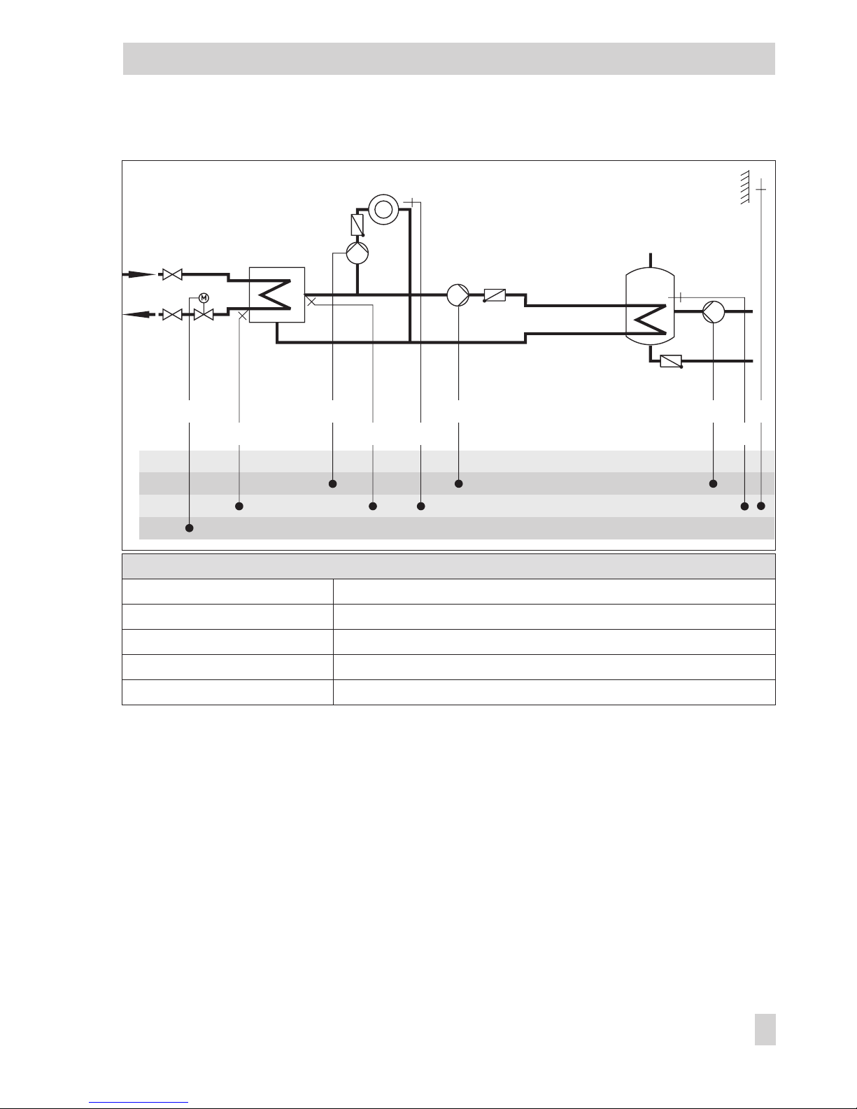
6.2 DHW heating in the storage tank charging system
Start storage tank charging
The controller begins charging the storage tank when the water temperature measured at
sensor SS1 falls below the
DHW temperature set point
by 0.1 °C. If the flow temperature in
the system exceeds the desired charging temperature, the controller tries to reduce the flow
temperature in the heating circuit for up to 3 minutes before the exchanger charging pump is
activated together with the storage tank charging pump.
When there is no heating operation or when the flow temperature in the system is lower, the
exchanger charging pump is switched on immediately. If the temperature currently measured
at sensor SS1 is reached at sensor VS, the storage tank charging pump is switched on. A
blinking icon during such operating periods indicates active charging preparations.
If a storage tank thermostat is used, the storage tank charging pump is switched on when the
temperature T =
charging temperature
– 5 °C is reached at sensor VS.
Note!
Instead of the
DHW temperature
parameter, the
Charging temperature
can be set as the ab
-
solute value at the rotary switch if a storage tank thermostat is used.
When the flow sensor VS2 is activated, control is switched from VS1 to VS2 upon activation
of the storage tank charging pump. The set point reading of the charging temperature also
changes from this point in time from VS1 to VS2. The
Maximum charging temperature
can
be read off at the measured value VS1.
Due to the transfer performance of the heat exchanger, which may deteriorate over the oper
-
ating time, the flow temperature at VS1 tends to increase in level. When it reaches the pa
-
rameter value
Max. charging temperature
in the heat exchanger circuit, the flow temperature
remains limited to this level; Alarm “Err 4“ is generated. The alarm can be confirmed by
pressing the rotary pushbutton in the error level.
EB 5433 EN 51
Functions of the DHW circuit
WW
SS1
SS2
VS
SLP
TLP
ZP
KW
Fig. 8 · Design of a storage tank charging system
TLP Exchanger charging pump
VS Flow sensor
SLP Storage tank charging pump
SS1 Storage sensor 1
SS2 Storage sensor 2
ZP Circulation pump
WW Warm water
KW Cold water
Page 52

If times-of-times have been set for DHW heating, the
Set point DHW temperature
adjusted at
the rotary switch is applied during these times-of-use.
Outside the times-of-use, the
Sustained DHW temperature
parameter is used. This does not
apply when a storage tank thermostat is used.
Stop storage tank charging
The controller stops charging the storage tank when the temperature measured at sensor SS2
has reached the value T =
DHW temperature+hysteresis
.
When there is no heating operation or when the flow temperature demand in the system is
lower, the valve is closed.
The exchanger charging pump is switched off when the limit temperature for
Stop charging
has been reached, at the latest, however, after approx. 3 minutes; with a certain delay, the
storage tank charging pump is deactivated as well. When flow sensor VS2 is activated, the
storage tank charging pump is switched off with a certain delay when the limit temperature
Storage tank charging pump OFF
has been reached, at the latest, however, after approx.
3 minutes.
In system Anl 6, it is also possible to link the circulation pipe into the heat exchanger (dashed
line in the schematics). In this case, the regulation of the charging temperature and the operation of the heat exchanger charging pump remain active even outside the heat exchanger
charging times depending on the times-of-use of the circulation pump.
52 EB 5433 EN
Functions of the DHW circuit
Page 53

Functions
WE Configuration
Storage sensor SS1 1 CO2 -> F01 - 1
Storage sensor SS2 1 CO2 -> F02 - 1
Flow sensor VS2 0 CO2 -> F03
Parameter
WE Rotary switch / Range of values
DHW temperature set point 55 °C Min. to max. DHW temperature
Parameters
WE Parameter level / Range of values
Min. DHW temperature* 40 °C PA2 / 20 to 90 °C
Max. DHW temperature* 60 °C PA2 / 20 to 90 °C
Hysteresis** 5 °C PA2 / 0 to 30 °C
Charging temperature boost*** 10 °C PA2 / 0 to 30 °C
Stop charging 53 °C PA2 / 20 to 90 °C
Storage tank charging pump OFF 53 °C PA2 / 20 to 90 °C (only Anl 3 with VS2)
Max. charging temperature 80 °C PA2 / 20 to 120 °C (only Anl 3 with VS2)
Sustained DHW temperature 40 °C PA2 / 20 to 90 °C
* Parameters serve as limitation of the adjustment range for the DHW temp. to be set at the rotary switch
** Deactivation value T =
DHW temperature
+ hysteresis
*** Charging temperature T =
DHW temperature+charging temperature boost
EB 5433 EN 53
Functions of the DHW circuit
Page 54

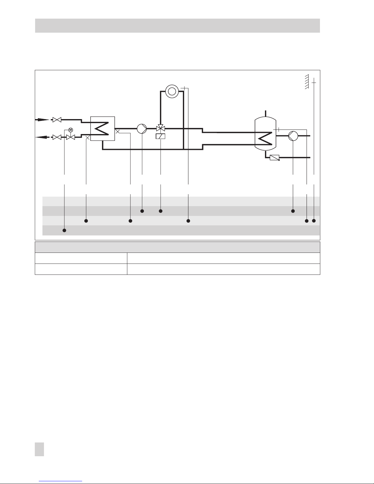
6.3 DHW heating in the instantaneous water system
DHW heating in a system with an instantaneous water heater can be configured using sys
tem Anl 5.
A hydraulic pressure switch signals the controller the beginning and end of DHW tapping.
When the pressure switch makes contact, the exchanger charging pump starts operation and
DHW temperature control at sensor VS2 is activated.
When the contact is open, the control valve shuts off the DHW circuit. The exchanger charging pump is deactivated with a certain delay.
Note!
Control of the exchanger charging pump is only possible if the Fault alarm output BA function has been deactivated.
Functions
WE Configuration
Instantaneous heating system with hydraulic
pressure switch
0
2.0
120 sec
0 sec
1.0
45 sec
CO2 -> F14 - 1
K
P
(proportional gain) / 0.1 to 50.0
T
N
(reset time) / 0 to 999 sec
d component / 0 to 999 sec
K
PTV
(d component of the proportional
gain) / 0.1 to 10.0
T
Y
(valve transit time) / 10 to 240 sec
Fault alarm output BA 1 CO-SYS -> F13 - 0
Parameter
WE Rotary switch / Range of values
DHW temperature set point 55 °C Min. to max. DHW temperature
54 EB 5433 EN
Functions of the DHW circuit
WW
ZP
VS2
TLP
FDS
KW
Fig. 9 · Schematics of a system with instantaneous water heater
TLP Exchanger charging pump
VS2 Flow sensor
FDS Hydraulic pressure switch
ZP Circulation pump
WW Warm water
KW Cold water
Page 55

6.4 Intermediate heating operation
This function is only available in systems Anl 2 and 3. With the setting CO2 -> F10 - 1, heat
ing operation is reactivated for 10 minutes after 20 minutes of priority (heating deactivated
during DHW heating). By setting CO2 -> F10 - 0, storage tank charging is given unlimited
priority over heating operation.
Functions
WE Configuration
Parallel pump operation 0 CO2 -> F06 - 0
Intermediate heating 1 CO2 -> F10 - 1
6.5 Parallel pump operation
This function is only available in Anl 2 and 3. With the setting CO2 -> F06 - 1, the circula
tion pump UP remains switched on during DHW heating unless certain operating situations
occur. The operating situations that do not apply include those in which the actual set point
for the heating circuit is less than 40 °C or in which the
Max. flow temperature
would be exceeded. In these cases, the controller applies priority operation. Once a parallel pump operation cycle has been activated and the time for
Stop parallel operation in case of deviation
has elapsed, system deviations greater than 5 °C cause the controller to suspend parallel operation for 10 minutes and to apply priority operation.
If the
Stop parallel operation in case of deviation
is set to – – –, the parallel operation re-
mains active regardless of any deviations.
Functions
WE Configuration
Parallel pump operation 0
600 sec
CO2 -> F06 - 1, option: 1
Stop parallel operation in case of deviation /
–––,60to600sec
Intermediate heating 1 CO2 -> F10 - 0
6.6 Operation of circulation pump during storage tank charging
This function is only available in Anl 2, 3, 4 and 6. With the setting CO2 -> F04 - 1, the cir
culation pump continues operation according to the set schedule even during storage tank
charging. With the setting CO2 -> F04 - 0, the circulation pump is switched off as soon as
the storage tank charging pump is activated. The circulation pump returns to operate accord
-
ing to schedule when the storage tank charging pump has been switched off again.
EB 5433 EN 55
Functions of the DHW circuit
Page 56

Function
WE Configuration
Operation of circulation pump during storage
tank charging
0 CO2 -> F04
6.7 Priority operation
In many district heating systems with primary DHW heating, the allotted amount of water is
only intended to supply the heating system. As a result, the capacity required for DHW heat
ing needs to be taken from the heating system when great heating loads occur; and this, until
DHW heating has been concluded.
Nevertheless, heating operation is not to be interrupted simply. Only the amount of energy
required for DHW heating is to be deducted. This can be achieved by using the priority func
-
tions Reverse control and Set-back operation.
6.7.1 Reverse control
In systems Anl 4 and 5, DHW heating can be given priority by applying reverse control.
With the setting CO2 -> F09 - 1, option
1
allows the temperature at VS2 is monitored. If the
temperature at VS2 is still 5 °C lower than
Monitoring value
after the time for
Activate prior-
ity in case of deviation
has elapsed, the set point of the heating circuit is gradually reduced
each minute until the flow temperature set point has reached 20 °C at the minimum provided
the
DHW temperature set point
has still not been reached.
If the temperature at VS2 rises above
Monitoring value
minus 5 °C, the reduced flow temperature set point in the heating circuit is initially kept. First when the temperature at VS2 is
greater than the
Monitoring value,
the flow temperature set point of the heating circuit is
gradually raised each minute.
Function
WE Configuration
Priority through reverse control 0
300 sec
40 °C
CO2 -> F09 - 1, option: 1
Activate priority in case of deviation / 60 to 600 sec
Monitoring value / 20 to 90 °C
6.7.2 Set-back operation
In systems Anl 4 and 5, DHW heating can be given priority by applying set-back operation.
With the setting CO2 -> F09 - 1, option
2
allows the temperature at VS2 is monitored. If the
temperature at VS2 is still lower than
Monitoring value
minus 5 °C after the time for
Activate
priority in case of deviation
has elapsed, the heating circuit is set to reduced operating mode
or reduced by a corresponding amount in case the heating circuit was already in reduced
operating mode. First when the temperature at VS2 is greater than the
Monitoring value,
the
56 EB 5433 EN
Functions of the DHW circuit
Page 57

reduced operating mode stops after the time for
Activate priority in case of deviation
has
elapsed.
Function
WE Configuration
Priority through set-back
operation
0
300 sec
40 °C
CO2 -> F09 - 1, option: 2
Activate priority in case of deviation / 60 to 600 sec
Monitoring value / 20 to 90 °C
6.8 Forced charging of the DHW storage tank
To provide the full room heating performance when the time-of-use of the heating circuits be
-
gins, existing storage tanks are charged one hour before the time-of-use of the heating cir
cuits starts. For the individual controller, this means that storage tank charging is activated
when the water temperature in the storage tank falls below the adjusted deactivation value of
T =
DHW temperature+hysteresis
. The forced charging of the storage tank does not occur
when the DHW circuit is not used at the beginning of the time-of-use set for the heating circuit.
Note! This function is not available when a storage tank thermostat is used.
6.9 Thermal disinfection of the DHW storage tank
In all systems with DHW storage tank, the DHW storage tank is thermally disinfected on a
selected
Day of the week
or every day.
The tank is heated up to the adjusted
Disinfection temperature
, taking into account the
Charging temperature boost
. Disinfection begins at the adjusted
Start time
and, at the latest,
ends at the specified
Stop time
set in CO2 -> F20 - 0. In case of the Time-controlled thermal
disinfection (CO2 -> F20 - 1), the disinfection remains active even after the
Disinfection tem
-
perature
is reached and ends at the adjusted
Stop time
.
In addition to this function or instead of it, the thermal disinfection can be activated by a bi
-
nary input. The binary input, which initates the thermal disinfection process, functions either
as a momentary-action switch or a latching-action switch:
4
Functioning as a momentary-action swtich, the floating switch at input RS leads to the
next programmed thermal disinfection running right through from the
Start time
to the
Stop time
.
4
Functioning as a latching-action switch, a closed contact of the floating switch at input RS
leads to the thermal disinfection being active until the contact is opened again.
blinks while the thermal disinfection is active.
EB 5433 EN 57
Functions of the DHW circuit
Page 58

If the
Disinfection temperature
has not been reached in the tank and, when a circulation sen
sor ZS (in Anl 6 only) is used, at this sensor as well before the end of the thermal disinfection
cycle, “Err 3“ alarm is generated. The alarm is automatically reset when the
Disinfection tem
-
perature
is properly reached during the following thermal disinfection cycle. The alarm can
be confirmed by pressing the rotary pushbutton in error level.
If required, the controller can indicate an active thermal disinfection using an activated bi
nary output BA. If this function is active, the collective alarm and boiler demand functions,
which use the same binary output, are automatically deactivated.
Thermal disinfection for preventing legionella infection causes
4
excessively high return flow temperatures during the disinfection cycle (return flow tem
-
perature limitation suspended),
4
excessively high storage temperatures after thermal disinfection has been concluded,
4
lime precipitation, which may have a negative effect on heat exchanger performance.
Note! This function is not available when a storage tank thermostat is used.
Function
WE Configuration
Thermal disinfection 0
3
0:00 h
4:00 h
70 °C
CO2 -> F05 - 1
Day of the disinfection / 0, 1, 2, ..., 7, with 0 = daily,
1 = Monday, 2 = Tuesday, ..., 7 = Sunday
Start time / 0:00 h to 23:30 h
Stop time / 0:00 h to 23:30 h
Disinfection temperature / 60 to 90 °C
Circulation sensor ZS 0 CO2 -> F17 - 1
Thermal disinfection over a binary
input
0
0:00 h
4:00 h
70 °C
CO2 -> F19 - 1
Function block parameters only when CO2 -> F05 - 0:
Start time / 0:00 h to 23:30 h
Stop time / 0:00 h to 23:30 h
Disinfection temperature / 60 to 90 °C
Time-controlled disinfection 0 CO2 -> F20 - 1
Binary output BA activated during
thermal disinfection
0 CO-SYS -> F16 - 1
58 EB 5433 EN
Functions of the DHW circuit
Page 59

6.10 Vacation periods and public holidays for DHW heating
With the default settings, the adjusted public holidays and vacation periods are only valid
for the heating circuit. The times-of-use set for Sunday for the DHW circulation pump and for
DHW heating can also be applied on public holidays, provided the Vacations and holidays
also valid for DHW function has been activated. This function also deactivates DHW heating
during the adjusted vacation periods (frost protection).
Function
WE Configuration
Vacations and holidays also valid for DHW 0 CO2 -> F07 - 1
EB 5433 EN 59
Functions of the DHW circuit
Page 60

7 System-wide functions
7.1 Automatic summer time/winter time changeover
The clock is automatically adjusted on the last Sunday in March at 2.00 h and on the last
Sunday in October at 3.00 h.
Function
WE Configuration
Summer time/winter time
changeover
1 CO-SYS -> F03 - 1
7.2 Frost protection
The heating system is automatically monitored for frost.
The following activation criteria and frost protection measures apply:
Activation criteria Frost protection measures
Heating operation is active and the outdoor temperature falls below 3 °C.
None
Heating operation is either switched off at
the operating modes switch ( , ) or
suspended in optimizing mode and the
outdoor temperature falls below 3 °C.
Controlled to a flow temperature set point of 20 °C.
Heating circulation pump and circulation pump are
switched on.
In weather-compensated or room temperature dependent flow temperature control
(not fixed set point control), the flow tem
-
perature falls below 5 °C.
Controlled to a flow temperature set point of 20 °C for 5
minutes.
DHW temperature falls below 5 °C. DHW storage tank is charged.
In the instantaneous system, a DHW temperature of 10 °C
is maintained.
Note! Frost-protection-induced operation of a pump, the heating circuit or the DHW circuit
only applies when the frost protection icon appears on the display.
7.3 Forced operation of the pumps
When the heating circuit pump has not been activated for 24 hours, forced operation of the
pump is started between 12.00 h and 12.01 h to prevent the pump from getting stuck when
it is not operated for a longer period of time.
The other pumps are operated between 12.01 h and 12.02 h.
60 EB 5433 EN
System-wide functions
Page 61

7.4 Return flow temperature limitation
The temperature difference between the flow and return flow in a system indicates how well
the energy is used: the greater the difference, the higher the efficiency. A return flow sensor
is sufficient to evaluate the temperature difference when the flow temperatures are preset.
The return flow temperature can be limited either to a value depending on the outdoor tem
-
perature (variable) or to a fixed value. When the temperature measured at return flow sen
sor RüS exceeds the limit value, the set point of the flow temperature (flow temperature of the
heating system, charging temperature) is reduced. As a result, the primary flow rate is re
-
duced and the return flow temperature falls. The
Limiting factor
determines how strongly the
controller responds when the limit values are exceeded in either direction. The values of the
actual return flow temperature and of the set point (flow temperature of the heating system,
charging temperature) blink on the display when limitation is applied. In Anl 2 and 3 the
Max. return flow temperature
parameter (PA2 level) is used for limitation.
In Anl 5 with separate RüS_TW, the
Max. return flow temperature
parameter (PA2 level)
only affects the DHW circuit.
Note!
Using weather-compensated control with gradient characteristic, the return flow temperature
is limited to a fixed value by equating the parameters
Return flow temperature foot
and
Max.
return flow temperature
(PA1).
Functions
WE Configuration
Return flow sensor RüS 1 CO-SYS -> F01 - 1*
Return flow sensor RüS_TW 1 CO2 -> F12 - 1* (Anl 5)
Control mode DHW 1 CO2 -> F11 - 1 (Anl 5)
Instantaneous heating system with
hydraulic pressure switch
0 CO2 -> F14 - 0 (Anl 5)
1.0 *Limiting factor / 0.1 to 10.0
Parameters
WE Parameter level / Range of values
Gradient, return flow 1.2 PA1 / 0.2 to 3.2
Level, return flow 0 °C PA1 / –30 to 30 °C
Return flow temperature foot 65 °C PA1 / 20 to 90 °C
Max. return flow temperature 65 °C PA1 / 20 to 90 °C
or
EB 5433 EN 61
System-wide functions
Page 62

Parameters
WE Parameter level / Range of values
Return flow temp. points 1 to 4 65 °C PA1 / 20 to 90 °C
Max. return flow temperature 65 °C PA2 / 20 to 90 °C
Note!
To ensure that the preset return flow temperature limiting value can be met, make sure that
– the heating characteristic has not been adjusted to ascent too steeply,
– the circulation pumps have not been adjusted to run at excessive speed,
– the heating systems have been calibrated.
7.5 Condensate accumulation control
Activate the Limit deviation for OPEN signal function to start up condensate accumulation
control plants, in particular to avoid problematic excess temperatures. The controller response to set point deviations that cause the primary valve to open is attenuated. The controller response to set point deviations that cause the control valve to close remains unaffected.
Function
WE Configuration
Limit deviation for OPEN signal 0
2 °C
CO-SYS -> F06 - 1
Max. deviation / 2 to 10 °C
In system Anl 5, the Limit deviation for OPEN signal function can be separately selected for
the DHW circuit.
Function
WE Configuration
Limit deviation for OPEN signal
(DHW circuit)
0
2 °C
CO2 -> F15 - 1
Max. deviation / 2 to 10 °C
Note!
The condensate accumulation control function can only be activated when no on/off control
has been configured (CO-SYS -> F05 - 1 or CO2 -> F11 - 1).
62 EB 5433 EN
System-wide functions
Page 63

7.6 Three-step control
The flow temperature can be controlled using a PI algorithm. The valve reacts to pulses that
the controller emits upon an existing system deviation. The length of the first pulse, in particu
-
lar, depends on the extent of the system deviation and the selected
Proportional gain K
P
(the
pulse length increases as K
P
increases). The pulse and pause lengths change continuously un
til the system deviation has been eliminated.
The pause length between the single pulses is greatly influenced by the
Reset time T
N
(the
pause length increases as T
N
increases). The
Valve transit time T
Y
specifies the time required
by the valve to travel through the range of 0 to 100 %.
In system Anl 5, two control valves are controlled. Consequently, the control mode needs to
be set for the DHW circuit as well.
Functions
WE Configuration
Control mode 1
2.0
120 sec
45 sec
CO-SYS -> F05 - 1
K
P
(proportional gain) / 0.1 to 50.0
T
N
(reset time) / 0 to 999 sec
T
Y
(valve transit time) / 10 to 240 sec
Control mode DHW 1
2.0
120 sec
45 sec
CO2 -> F11 - 1
K
P
(proportional gain) / 0.1 to 50.0
T
N
(reset time) / 0 to 999 sec
T
Y
(valve transit time) / 10 to 240 sec
7.7 On/off control
The flow temperature can be controlled, for example, by activating and deactivating a
boiler. The controller switches on the boiler when the flow temperature falls below the set
point by T = 0.5 x
hysteresis
. When the set point is exceeded by T = 0.5 x
hysteresis
, the
boiler is switched off again. The greater the value you choose for
Hysteresis
, the lower will
be the activation/deactivation frequency. By setting the
Minimum ON time
, an activated
boiler remains switched on during this period regardless of the flow temperature fluctuations.
Similarly, a deactivated boiler will remain switched off regardless of the flow temperature
fluctuations if the
Min. OFF time
has been specified.
Functions
WE Configuration
Control mode 1
5 °C
120 sec
120 sec
CO-SYS -> F05 - 0
Hysteresis / 2 to 10 °C
Min. ON time / 0 to 600 sec
Min. OFF time / 0 to 600 sec
EB 5433 EN 63
System-wide functions
Page 64

Functions
WE Configuration
Control mode DHW 1
5 °C
120 sec
120 sec
CO2 -> F11 - 0
Hysteresis / 2 to 10 °C
Min. ON time / 0 to 600 sec
Min. OFF time / 0 to 600 sec
7.8 Requesting/processing external demand
Requesting external demand
In more complex heating systems, the flow temperature set points can be forwarded from
controller to controller. The external flow set point of the previous controller is read over ana
log input UE and compared to the controller's own flow set point. The higher of the two flow
set points is forwarded to the next controller over output UA. On forwarding to other sys
tems, it may be necessary to change the transmission range of the 0-10 V signal. Any
changes in transmission range only apply to the analog output UA. The assignment 0 to
10 V = 0 to 120 °C still applies to the analog input UE.
In systems with storage tank thermostat, the
Requested value
parameter can be changed as
required. It determines the minimum value of the output signal to UA when the storage tank
charging is active.
In systems with storage tank sensors, the
Requested value
is calculated from the current set
point of the storage tank
(DHW temperature set point, Sustained DHW temperature or Disin-
fection temperature)
plus
Charging temperature boost
plus
Boost
(alternative function block
parameter to
Requested value
).
Functions
WE Configuration
External demand, request 0
0 °C
120 °C
70 °C
0
CO-SYS -> F10 - 1
Transmission lower range value / 0 to 130 °C
Transmission upper range value / 0 to 130 °C
Requested value /20 to 90 °C (Anl 4, 5 and 6
only)
Boost/0to30°C(alternative)
External demand, processing 0 CO-SYS -> F11 - 0
Forward outdoor temperature, 0 to 10 V 0 CO-SYS -> F12 - 0
Furthermore, the binary output BA in the systemes Anl 1, 4 and 6 can configure for floating
boiler demand:
Function
WE Configuration
Fault alarm output BA 1 CO-SYS -> F13 - 0
64 EB 5433 EN
System-wide functions
Page 65

Processing external demand
The controller (= primary controller) can process analog requests for an externally required
signal, provided the analog request can be matched to “0 to 10 V correspond with 0 to
120 °C flow temperature“. The highest flow set point of the subsequent controller (= second
ary controller) is read over analog input UE and compared to the controller's own flow set
point. The higher of the two flow set points plus the value of the
Boost
parameter is adjusted
(at least 20 °C flow temperature from 1 V input signal).
The
Boost
parameter improves the control response of the subsequent control valves in the
heating circuit and compensates for performance losses.
Note!
The adjustment of an external demand is indicated by displaying the icon in info level.
The primary controller can be configured to operate with or without outdoor sensor:
4
Primary controller with outdoor sensor:
As illustrated in Fig. 10, the primary controller can supply its measured outdoor temperature value at output UA (0 to 10 V); 0 to 10 V = –40 to 50 °C outdoor temperature applies.
The secondary controller reads the outdoor temperature over input UE and uses this value
to determine its flow temperature set point.
EB 5433 EN 65
System-wide functions
WW
SS1'
KW
RüS
VS1
AS
VS1'
Fig. 10 · Processing of external demand in primary controllers with outdoor sensors
5433 Anl 1 5433 Anl 4
Page 66

Primary controller:
Functions
WE Configuration
Outdoor temperature t
A
1 CO1 -> F07 - 1
Outdoor temperature 0 to 10 V at input UE 0 CO1 -> F08 - 0
External demand, request 0 CO-SYS -> F10 - 0
External demand, processing 0
0 °C
CO-SYS -> F11 - 1
Boost / 0 to 30 °C
Forward outdoor temperature, 0 to 10 V 0 CO-SYS -> F12 - 1
Secondary controller:
Functions
WE Configuration
Outdoor temperature t
A
1 CO1 -> F07 - 1
Outdoor temperature 0 to 10 V at input UE 0 CO1 -> F08 - 1
External demand, request 0
70 °C
CO-SYS -> F10 - 1
Requested value / 20 to 90 °C
External demand, processing 0 CO-SYS -> F11 - 0
Primary controller without outdoor sensor:
The controller is configured for demand-driven heat exchanger control with control of the
feeder pump. Operation of the feeder pump and heat exchanger control are exclusively released by the received demand signal, not over a time schedule. Demand signals between
1 V and 10 V activate the feeder pump and cause the requested flow temperature (at least
20 °C to 120 °C) plus the adjusted
Boost
to be adjusted. Demand signals below 1 V are not
processed; they cause the primary valve to be closed and deactivate the feeder pump with a
certain delay. The deactivation delay for the feeder pump can be adjusted.
66 EB 5433 EN
System-wide functions
Page 67

Primary controller:
Functions
WE Configuration
Outdoor temperature t
A
1 CO1 -> F07 - 0
External demand, request 0 CO-SYS -> F10 - 0
External demand, processing 0
0 °C
CO-SYS -> F11 - 1
Boost / 0 to 30 °C
Forward outdoor temperature, 0 to 10 V 0 CO-SYS -> F12 - 0
Parameter
WE Parameter level / Range of values
Lag time of heating circulation pump 180 sec PA1 / 15 to 2400 sec
Secondary controller:
Functions
WE Configuration
Outdoor temperature t
A
1 CO1 -> F07 - 1
Outdoor temperature 0 to 10 V at input UE 0 CO1 -> F08 - 0
External demand, request 0
70 °C
CO-SYS -> F10 - 1
Requested value / 20 to 90 °C
External demand, processing 0 CO-SYS -> F11 - 0
EB 5433 EN 67
System-wide functions
WW
SS1'
KW
RüS
VS1
AS'
VS1'
Fig. 11 · External demand processing in primary controllers without outdoor sensors
5433 Anl 1
5433 Anl 4
Page 68

7.9 Locking the manual level
To protect the heating system, this function can be used to lock the manual level. When this
function has been activated, automatic mode is started when the rotary switch is set to man
-
ual operating mode (– 0 +).
Function
WE Configuration
Locking the manual level 0 CO-SYS -> F04 - 1
7.10 Locking the rotary switches
When this function has been activated, the controller remains in automatic mode regardless
of the rotary switch positions that have been adjusted. The rotary switch “Configuration and
parameterization“ can only be used to switch between “COPA“- (key number required) and
“INFO“ level.
Function
WE Configuration
Locking the rotary switches 0 CO-SYS -> F15 - 1
68 EB 5433 EN
System-wide functions
Page 69

8 Operational faults
Malfunctions or faults are indicated by the blinking icon on the display. In addition, the
“Err“ alarm is displayed immediately. Press the rotary pushbutton to open error level. It may
be possible to view several alarms by turning the rotary pushbutton. As long as an error
alarm is present, error level is displayed, even though it has not been opened by pressing the
rotary pushbutton.
In error level, the error alarm is displayed as specified in the list below.
8.1 Error alarm list
4
Err 0 = Hardware error (rotary switch position not identified; EEPROM faulty)
4
Err 1 = Sensor failure (–> section 8.2)
4
Err 2 = Reset to default values (after automatic cold start with default values in Anl 1)
4
Err 3 = Disinfection temperature not reached (–> section 6.9; confirmation over rotary
pushbutton)
4
Err 4 = Max. charging temperature reached (–> section 6.2; confirmation over rotary
pushbutton)
4
Err 5 = Device not calibrated (confirmation over rotary pushbutton)
4
Err 6 = Temperature monitoring (–> section 8.3; confirmation over rotary pushbutton)
/drying of jointless floor cancelation
8.2 Sensor failure
According to the error list, sensor failures are indicated by displaying “Err 1“ in error level.
For detailed information, exit error level and view the different temperature values in info
level: each sensor icon displayed together with (= sensor short-circuited) or (= sensor
interrupted) instead of the measured value indicates a defective sensor. The following list ex
-
plains how the controller responds to the failure of the different sensors.
4
Outdoor sensor AS: When the outdoor sensor fails, the controller adjusts a flow tempera
-
ture set point of 50 °C or the
Max. flow temperature
when the
Max. flow temperature
(adjusted under PA1) is smaller than 50 °C.
4
Flow sensor VS1: When the flow sensor in the heating circuit fails, the associated valve
moves to 30 % travel. DHW heating using such a sensor to measure the charging temper
-
ature is suspended.
EB 5433 EN 69
Operational faults
Page 70

4
Flow sensor in the DWH circuit VS2: When the sensor VS2 in Anl 3 fails, the flow tem
perature set point for DHW heating is only controlled with VS1.
In Anl 4, DHW heating is no longer given priority.
In Anl 5, the DHW is no longer heated.
4
Return flow sensor RüS_TW: When the return flow sensor fails, the controller continues
operation without return flow temperature limitation.
4
Room sensor RS: When the room sensor fails, the controller uses the settings for opera
tion without room sensor. The controller, for example, switches from optimizing mode to
reduced operation.
4
Storage sensors SS1/2: When one of the two sensors fails, the storage tank is no longer
charged.
4
Circulation sensor ZS: When the sensor ZS fails, the controller continues to function as if
the sensor ZS has not been configured.
8.3 Temperature monitoring
When certain measured values deviate by a specified value from their set points, an alarm is
triggered. The following deviations generate “Err 6“ alarms:
4
The flow temperature deviates by at least 10 °C from its set point for longer than 30 min,
4
The room temperature remains at least 2 °C below its set point for longer than 30 min
(flash adaptation active),
4
The return flow temperature limitation has been interfering continuously for longer than
30 min.
Function
WE Configuration
Temperature monitoring 0 CO-SYS -> F14 - 1
8.4 Collective alarm
When this function is active, binary output BA is activated in case of a fault. Alarms are still
indicated in info level by displaying “Err“.
Function
WE Configuration
Fault alarm output BA 0 CO-SYS -> F13 - 1
70 EB 5433 EN
Operational faults
Page 71

9 Memory pen
A memory pen (accessories; order no. 1400-7697) is particularly useful to transfer all data
from one TROVIS 5433 Controller to several other TROVIS 5433 Controllers. The memory
pen is plugged into the connector integrated into the front panel. Once the pen has been
connected, “33 SP“ is displayed. If the memory pen already contains data from a different
TROVIS 5433 controller, turn the rotary pushbutton until “SP 33“ is displayed.
4
Pressing the rotary pushbutton to confirm “33 SP“ causes the controller settings to be
transferred to the memory pen.
4
Pressing the rotary pushbutton to confirm “SP 33“ causes the saved controller settings to
be transferred from the memory pen to the controller.
During the data transfer, the bars on the display indicate the progress of the transfer. When
the bars have stopped indicating the transfer progress, the connection between controller
and memory pen can be terminated.
A database module for the use of the TROVIS 5433 Controller together with the
TROVIS-VIEW 6661 software is available (accessories; order no. 6661-1003). The memory
pen needs to be connected to the PC over a serial interface adapter (accessories; order no.
1400-7700). In addition, a complete hardware package (including 1 memory pen, 1 serial
interface adapter and 1 connecting cable for direct connection between controller and PC) is
available as an accessory (order no. 1400-7704).
Using TROVIS-VIEW, it is possible to adjust all controller settings in a convenient user interface and transfer them to a memory pen. In addition, data can be read from a memory pen
to change or print them.
EB 5433 EN 71
Memory pen
Page 72

10 Installation
The controller consists of the housing with the electronics and the back panel with the termi
-
nals. It is suitable for panel, wall and top hat rail mounting (Fig. 12).
Panel mounting
1. Remove both screws (1).
2. Pull apart the controller housing and the back panel.
3. Make a cut-out of 138 x 92 mm (W x H) in the control panel.
4. Insert the controller housing through the panel cut-out.
5. Insert one mounting clamp (2) each at the side. Screw the threaded rod towards the
panel with a screwdriver so that the housing is clamped against the control panel.
6. Install the electrical connections at the back of the housing as described in section 11.
7. Fit the controller housing.
8. Fasten both screws (1).
Wall mounting
1. Remove both screws (1).
2. Pull apart the controller housing and the back panel.
3. If necessary, bore holes with the specified dimensions in the appropriate places.
Fasten the back panel with four screws.
4. Install the electrical connections at the back of the housing as described in section 11.
5. Remount the controller housing.
6. Fasten both screws (1).
Top hat rail mounting
1. Fasten the spring-loaded hook (4) at the bottom of the top hat rail (3).
2. Slightly push the controller upwards and pull the upper hook (5) over the top hat rail.
3. Remove both screws (1).
4. Pull apart the controller housing and the back panel.
5. Install the electrical connections at the back panel as described in section 11.
6. Remount the controller housing.
7. Fasten both screws (1).
72 EB 5433 EN
Installation
Page 73

EB 5433 EN 73
Installation
41
70
14
62
5
5
4
3
57
2
2
1
Fig. 12 · Installation
Panel mounting
Controller housing
Back panel of
the controller
Wall mounting
Top hat rail mounting
Dimensions in mm
W x H x D = 144 x 97 x 130
Page 74

11 Electrical connection
Caution!
For electrical installation, you are required to observe the relevant electrotechnical regula
tions of the country of use as well as the regulations of the local power suppliers. Make sure
all electrical connections are installed by trained and experienced personnel!
Notes on installing the electrical connections
4
Install the 230 V power supply lines and the signal lines separately! To increase noise im
munity, observe a minimum distance of 10 cm between the lines. Make sure the minimum
distance is also observed when the lines are installed in a cabinet.
4
The lines for digital signals (bus lines) and analog signals (sensor lines, analog outputs)
must also be installed separately!
4
In plants with a high electromagnetic noise level, we recommend to use shielded cables
for the analog signal lines. Ground the shield at one side, either at the control cabinet inlet or outlet, using the largest possible cross-section. Connect the central grounding point
and the PE grounding conductor with a cable 10 mm² using the shortest route.
4
Inductances in the control cabinet, e.g. contactor coils, are to be equipped with suitable
interference suppressors (RC elements).
4
Control cabinet elements with high field strength, e.g. transformers or frequency converters, should be shielded with separators providing a good ground connection.
Overvoltage protection
4
If signal lines are installed outside buildings or over large distances, make sure appropri
-
ate surge or overvoltage protection measures are taken. Such measures are indispens
-
able for bus lines!
4
The shield of signal lines installed outside buildings must have current conducting capac
-
ity and must be grounded on both sides.
4
Surge diverters must be installed at the control cabinet inlet.
Connecting the controller
The controller is connected as illustrated in the diagram on page 75.
Open the housing to connect the cables. To connect the feeding cables, make holes in the
marked locations at the top, bottom or back of the rear part of the housing and fit suitable
grommets or screw joints.
74 EB 5433 EN
Electrical connection
!
Page 75

EB 5433 EN 75
Electrical connection
15
14
13
12
11
10
9
8
7
6
5
4
3
312
12 11 GND
GND
2
1
N
UP
TLP
SLP
ZP
HK_2-Pkt
HK_3-Pkt
+
_
L
L
RK
N
N
BA
16
17
18
19
20
21
22
23
24
25
26
27
28
29
30
SS2
SS1
VS2
FG
RS
RüS
VS1
X1
AS/ZS
GND
GND
PE
UE
UA
23
Fig. 13 · Wiring diagram Anl 1 to 4 and Anl 6
15
14
13
12
11
10
9
8
FDS/
RüS_TW
VS2
FG
RS
RüS
VS1
AS
GND
7
6
5
4
3
GND
GND
UE
UA
312
12 11 GND
2
1
16
17
18
19
20
21
22
23
24
25
26
27
28
29
N
UP
X1
PE
ZP
HK_3-Pkt
L
RK
L
+
_
+
_
TW_3-Pkt
N
N
L
TLP
30
HK_2-Pkt
20
TW_2-Pkt
23
Fig. 14 · Wiring diagram Anl 5
Page 76

Connecting the sensors
Cables with a min. cross-section of 0.5 mm² can be connected to the terminals at the back
panel of the housing.
Connecting the actuators
4
3-step or on/off outputs:
Connect cables with a min. cross-section of 1.5 mm² suitable for damp locations to the
terminals of the controller output. The direction of travel needs to be checked at start-up.
Note!
The motorized actuator is not automatically supplied with voltage by the controller. The actu
ator can be supplied over an external voltage source connected to terminal 22.
Alternatively, install a jumper between terminal 17 and terminal 22.
Connecting the pumps
Connect all cables with a min. cross-section of 1.5 mm² to the terminals of the controller as illustrated in the connection diagram.
Legend for connection diagram on page 75:
76 EB 5433 EN
Electrical connection
AS Outdoor sensor
FDS Hydraulic pressure switch
FG Potentiometer
RS Room sensor
RüS Return flow sensor
RüS_TW Return flow sensor for DHW heating
SS Storage sensor
VS Flow sensor
BA Binary output
HK Heating circuit
GND Ground
L
RK
Voltage supply for actuator
PE Grounding conductor
SLP Storage tank charging pump
TLP Exchanger charging pump
TW DHW circuit
UA Output for demand/outdoor temperature
UE Input for demand/outdoor temperature
UP Circulation pump (heating circuit)
ZP Circulation pump (DHW circuit)
Page 77

12 Appendix
12.1 Function block lists
CO1: Heating circuit (not system Anl 6)*
F Function WE Anl
Comment
Function block parameters / Range of values (default)
01 Room sensor RS 0 All* CO1 -> F01 - 1: Temperature display and input FG1 active;
Options: 1 Types 5244 or 5257-5 Room Panels
2 Standard sensor
Function block cannot be selected if
CO1 -> F02 - 1, options 2/3 or CO1 -> F03 - 1 or
CO1 -> F07 - 0 and CO-SYS -> F11- 1
02 Optimization 0 All* CO1-> F02 - 1: Optimization active;
Options: 1 ON acc. to t
A
, set-back acc. to schedule*,
only with CO1 -> F07 - 1
2 ON acc. to t
A
, OFF acc. to room sensor*,
only with CO1 -> F01 - 1 and CO1 -> F07 - 1
3 ON and OFF according to room sensor,
only with CO1 -> F01 - 1
* Function block parameter:
Advance heating time / 0 to 360 (120) min
03 Flash adaptation 0 All* CO1 -> F03 - 1 only with CO1 -> F01 - 1
Function block parameter:
Cycle time / 1 to 100 min (10 min)
Function block cannot be selected if
CO1 -> F07 - 0 and CO-SYS -> F11 - 1
04 Characteristic 0 All* CO1 -> F04 - 1: 4-point characteristic
CO1 -> F04 - 0: Gradient characteristic
05 Delayed outdoor
temperature
adaptation
0 All* CO1 -> F05 - 1 only with CO1 -> F07 - 1;
Options: 1 When outdoor temperature t
A
decreases
2 When outdoor temp. t
A
decreases and increases
Function block parameter:
Delay / 1 to 6 °C/h (3 °C/h)
EB 5433 EN 77
Appendix
Page 78

F Function WE Anl
Comment
Function block parameters / Range of values (default)
06 Summer mode 0 All* CO1 -> F06 - 1: Time-controlled summer mode,
only with CO1 -> F07 - 1
Function block parameters:
Start summer mode / 01.01 to 31.12 (01.06)
No. of days until activation/ 1 to 3 (2)
Stop summer mode / 01.01 to 31.12 (30.09)
No. of days until deactivation / 1 to 3 (1)
OT limit value summer mode/0to50°C(18°C)
07 Outdoor
temperature t
A
1 All* CO1 -> F07 - 1: Weather-compensated control active
CO1 -> F07 - 0: Fixed set point control
Function block cannot be selected if:
CO1 -> F05 - 1 or CO1 -> F06 - 1 or CO1 -> F08 - 1 or
CO-SYS -> F12 - 1 or CO1 -> F02 - 1, options 1/2
08 Outdoor
temperature 0 to
10 V at input UE
0 All* CO1 -> F08 - 1: t
A
at input UE,
only with CO1 -> F07 - 1 and CO-SYS -> F11 - 0
CO1 -> F08 - 0: t
A
at input AS
09 Drying of jointless
floor
0 All* CO1 -> F09 - 1: Start the drying of jointless floor program only
by selecting
START 1
Function block parameters:
Temperature rise / 1.0 to 10 °C / 24 h (5.0 °C / 24 h)
Maximum temperature / 25 to 60 °C (45 °C)
Maintaining time of maximum temperature/1to10days (4)
Temperature reduction / 0.0 to 10.0 °C / 24 h (5.0 °C/24 h)
Option: START 1
F Function block number, WE Default value, Anl System code number
78 EB 5433 EN
Appendix
Page 79

CO2: DHW circuit
F Function WE Anl
Comment
Function block parameters / Range of values (default)
01 Storage sensor SS1 1 2, 3,
4, 6
CO2 -> F01 - 1: Sensor SS1 ON
CO2 -> F01 - 0: Storage tank thermostat, only with CO2 -> F02 - 0
Function block cannot be selected if:
CO2 -> F02 - 1, CO2 -> F05 - 1, CO2 -> F08 - 1 or
CO2 -> F19 - 1
02 Storage sensor SS2 0 2 CO2 -> F02 - 1: Sensor SS2 ON, only with CO2 -> F01 - 1
1 3, 4,
6
03 Flow sensor VS2 0 3, 6 CO2 -> F03 - 1: Flow sensor VS2 to measure the storage tank
charging temperature active (control switchover)
04 Operation of
circulation pump
during storage tank
charging
0 2, 3,4CO2 -> F04 - 1: Circulation pump (ZP) operates according to
schedule during storage tank charging
05 Thermal
disinfection
0 2, 3,
4, 6
CO2 -> F05 - 1*: Function block parameters:
Day of the week / 0 to 7 (3) with 0 = every day
Start time / 0:00 h to 23:30 h (0:00 h)
Stop time / 0:00 h to 23:30 h (4:00 h)
Disinfection temperature / 60 to 90 °C (70 °C)
* In Anl 2, 3, 4 and 6: only with CO2 -> F01 - 1
In Anl 5: the function block cannot be selected if:
CO2 -> F13 - 1 or CO2 -> F14 - 1
06 Parallel pump
operation
0 2, 3 CO2 -> F06 - 1 only with CO2 -> F10 - 0;
Options: 1 Parallel pump operation with UP and SLP
2 Control of changeover valve and UP
Function block parameter (Anl 2, option 1 or Anl 3):
Stop parallel operation in case of deviation /– – –, 60 to 600 sec
(600 sec)
07 Vacations and
holidays also valid
for DHW
0 2, 3,
4, 5
CO2 -> F07 - 1: Vacations and holidays also apply to DHW
heating
EB 5433 EN 79
Appendix
Page 80

F Function WE Anl
Comment
Function block parameters / Range of values (default)
08 SLP ON depending
on return flow
temperature
02,
4*, 6
CO2 -> F08 - 1 only with CO2 -> F01 - 1 and CO-SYS -> F01 - 1
* In system Anl 4 only applicable when implemented as a
secondary system.
To do so, mount return flow sensor RüS in the primary circuit in
the heat exchanger of the storage tank charging system; the
sensor is not used for return flow temperature limitation!
09 Priority for DHW
heating
0 4, 5* CO2 -> F09 - 1: Options: 1 Reverse control
2 Set-back operation
Function block parameters:
Activate priority in case of deviation / 60 to 600 sec (300 sec)
Monitoring value / 20 to 90 °C (40 °C)
* Cannot be selected in Anl 5 if CO2 -> F13 - 1
10 Intermediate
heating
1 2, 3 CO2 -> F10 - 1: 10 min of intermediate heating after 20 min;
only with CO2 -> F06 - 0
CO2 -> F10 - 0: Priority for DHW heating
11 Control mode
DHW
1 5 CO2 -> F11 - 1: Three-step control
Function block parameters:
K
P
(proportional gain) / 0.1 to 50.0 (2.0)
T
N
(reset time) / 0 to 999 sec (120 sec)
T
Y
(valve transit time) / 10 to 240 sec (45 sec)
CO2 -> F11 - 0: On/off control
Function block parameters:
Hysteresis / 2 to 10 °C (5 °C)
Min. ON time / 0 to 600 sec (120 sec)
Min. OFF time / 0 to 600 sec (120 sec)
Function block cannot be selected if:
CO2 -> F13 - 1 or CO2 -> F14 - 1
12 Return flow sensor
DHW RüS_TW
1 5 CO2 -> F12 - 1: Return flow temperature limitation in DHW circuit
active, only with CO2 -> F11 - 1 and CO2 -> F14 - 0
Function block parameter:
Limiting factor / 0.1 to 10 (1.0)
13 On/off valve and
thermostat
0 5 CO2 -> F13 - 1: On/off valve (controlled over outputs DHW +
and DHW –) and thermostat at input VS2; only with CO2 -> F11
- 0 and CO2 -> F14 - 0
Function block parameter:
Valve transit time / 10 to 240 sec (45 sec)
CO2 -> F13 - 0: Temperature valve (output DHW+) and
temperature sensor at input VS2
80 EB 5433 EN
Appendix
Page 81

F Function WE Anl
Comment
Function block parameters / Range of values (default)
14 Instantaneous
system with
hydraulic pressure
switch
0 5 CO2 -> F14 - 1: Instantaneous system w. hydraulic pressure
switch
Function block parameters:
K
P
(proportional gain) / 0.1 to 50.0 (2.0)
T
N
(reset time) / 0 to 999 sec (120 sec)
d component / 0 to 999 sec (0 sec)
K
PTV
(proportional gain d component) / 0.1 to 10.0 (1.0)
T
Y
(valve transit time) / 10 to 240 sec (45 sec)
15 Limit deviation for
OPEN signal DHW
0 5 CO2 -> F15 - 1 only with CO2 -> F11-1orCO2->F14-1
Function block parameter:
Max. deviation / 2 to 10 °C (2 °C)
16 Release continuous
signal for DHW
0 5 CO2 -> F16 - 1 only with CO2 -> F11-1orCO2->F14-1;
continuous signal only for actuator with limit switch control
17 Circulation sensor 0 6 CO2 -> F17 - 1: Circulation sensor ZS for measuring the return
flow temperature of the circulation circuit is active
18 Circulation pump
integrated into heat
exchanger
0 6 CO2 -> F18 - 1: DHW circuit control active when the circulation
pump ZP is running
19 Thermal
disinfection over a
binary input
0 2, 3,
4, 5,
6
CO2 -> F19 - 1* with input RS functioning as a binary input
Function block parameters (only when CO2 -> F05 - 0):
Start time / 0:00 h to 23:30 h (0:00 h)
Stop time / 0:00 h to 23:30 h (4:00 h)
Disinfection temperature / 60 to 90 °C (70 °C)
* In Anl 2, 3, 4 and 6: only with CO2 -> F01 - 1
In Anl 5: the function block cannot be selected if:
CO2 -> F13 - 1 or CO2 -> F14 - 1
20 Time-controlled
thermal disinfection
0 2, 3,
4, 5,
6
CO2 -> F20 - 1: The thermal disinfection remains active in all
circumstances during the entire time (start time to stop time)
F Function block number, WE Default value, Anl System code number
EB 5433 EN 81
Appendix
Page 82

CO-SYS: General functions (all systems)
F Function WE Anl
Comment
Function block parameters / Range of values (default)
01 Return flow sensor
RüS
1 All CO-SYS -> F01 - 1: Return flow temperature limitation active;
Function block parameter:
Limiting factor / 0.1 to 10.0 (1.0)
Function block cannot be selected if CO2 -> F08 - 1
02 Sensor selection 1 All CO-SYS -> F02 - 1: Pt1000 sensors
CO-SYS -> F02 - 0: PTC sensors
03 Summer time/
winter time
changeover
1 All CO-SYS -> F03 - 1: Automatic changeover
04 Locking the manual
level
0 All CO-SYS -> F04 - 1: Manual level locked;
automatic mode applies in switch positions –, 0, +
05 Control mode 1 All CO-SYS -> F05 - 1: Three-step control
Function block parameters:
K
P
(proportional gain) / 0.1 to 50 (2.0)
T
N
(reset time) / 0 to 999 sec (120 sec)
T
Y
(valve transit time) / 10 to 240 sec (45 sec)
CO-SYS -> F05 - 0: On/off control
Function block parameters:
Hysteresis / 2 to 10 °C (5 °C)
Min. ON time / 0 to 600 sec (120 sec)
Min. OFF time / 0 to 600 sec (120 sec)
06 Limit deviation for
OPEN signal
0 All CO-SYS -> F06 - 1 only with CO-SYS -> F05 - 1
Function block parameter:
Max. deviation/2to10°C(2°C)
07 Release continuous
signal for heating
circuit
0 All CO-SYS -> F07 - 1 only with CO-SYS -> F05 - 1;
continuous signal only for actuator with limit switch control
08 Sensor calibration 0 All CO-SYS -> F08 - 1: Measured values of all connected sensors can
be calibrated
09 Default parameter
values
0 All CO-SYS -> F09 - 1: All parameters are reset to their default
values (WE)
82 EB 5433 EN
Appendix
Page 83

F Function WE Anl
Comment
Function block parameters / Range of values (default)
10 External demand,
request
0 1, 4,
5*, 6
CO-SYS -> F10 - 1: Secondary controller,
only with CO-SYS -> F11 - 0 and CO-SYS -> F12 - 0
Function block parameters
Transmission lower range value / 0 to 130 °C (0 °C)
Transmission upper range value / 0 to 130 °C (120 °C)
Additional parameter with Anl 4, 5* and 6:
With CO2 -> F01 - 0: Requested value / 20 to 90 °C (70 °C)
With CO2 -> F01 - 1: Boost / 0 to 30 °C (0 °C)
* In Anl 5, only with CO2 -> F11 - 1 and CO2 -> F14 - 0
11 External demand,
processing
0 1, 2,
3, 4,
5
CO-SYS -> F11 - 1: Primary controller, only with CO-SYS ->
F10 - 0 and CO1-> F08 - 0 and CO1 -> F01 - 0
Function block parameter:
Boost / 0 to 30 °C (0 °C)
12 Forward outdoor
temperature,
0 to 10 V
0 1, 2,
3, 4,
5
CO-SYS -> F12 - 1
Only with CO-SYS -> F10 - 0 and CO1 -> F07 - 1
13 Fault alarm outputBA1 All CO-SYS -> F13 - 1: Output BA is activated in case of fault
In systems Anl 1, 4, 6: CO-SYS -> F13 - 0: Output boiler demand
In system Anl 5: CO-SYS -> F13 - 0: Output for TLP activated
14 Temperature
monitoring
0 All CO-SYS -> F14 - 1: Temperature monitoring VS, RS and RüS
15 Locking the rotary
switches
0 All CO-SYS -> F15 - 1: Rotary switches locked
16 Binary output BA
activated during
thermal disinfection
0 2, 3,
4, 5,
6
CO-SYS -> F16 - 1
Only with CO-SYS -> F13 - 0
F Function block number, WE Default value, Anl System code number
EB 5433 EN 83
Appendix
Page 84

12.2 Parameter lists
PA1: Heating circuit
Display
Parameter designation
Range of values (default)
Gradient, flow
0.2 to 3.2 (1.8)
Only with CO1 -> F04 - 0 and CO1 -> F07 - 1.
Level, flow (parallel transport)
–30 to 30 °C (0 °C)
Only with CO1 -> F04 - 0 and CO1 -> F07 - 1.
Max. flow temperature
Min. flow temperature to 130 °C (90 °C)
Min. flow temperature
0 °C to max. flow temperature (20 °C)
84 EB 5433 EN
Appendix
Page 85

Display
Parameter designation
Range of values (default)
Gradient, return flow
0.2 to 3.2 (1.2)
Only with
CO1 -> F04 - 0 and CO1 -> F07 - 1 and CO-SYS -> F01 - 1.
Level, return flow
–30 to 30 °C (0 °C)
Only with
CO1 -> F04 - 0 and CO1 -> F07 - 1 and CO-SYS -> F01 - 1.
Max. return flow temperature
20 °C to 90 °C (65 °C)
Only with (CO1 -> F07 - 0 and CO-SYS -> F01 - 1) or
(CO1 -> F04 - 0 and CO1 -> F07 - 1 and CO-SYS -> F01 - 1).
Return flow temperature foot
20 °C to 90 °C (65 °C)
Only with
CO1 -> F04 - 0 and CO1 -> F07 - 1 and CO-SYS -> F01 - 1.
EB 5433 EN 85
Appendix
Page 86

Display
Parameter designation
Range of values (default)
4-point characteristic
Point 1: Outdoor temperature
Outdoor temperatures of the points 2, 3, 4 are marked by squares
below the numbers 2, 3, 4.
–30 to 50 °C
(point 1: –15 °C, point 2: –5 °C, point 3: 5 °C, point 4: 15 °C)
Only with CO1 -> F04 - 1 and CO1 -> F07 - 1.
4-point characteristic
Point 1: flow temperature
Flow temperatures of the points 2, 3, 4 are marked by squares
below the numbers 2, 3, 4.
20 to 130 °C
(point 1: 70 °C, point 2: 55 °C, point 3: 40 °C, point 4: 25 °C)
Only with CO1 -> F04 - 1 and CO1 -> F07 - 1
.
4-point characteristic
Point 1: Return flow temperature
Reduced flow temperatures of the points 2, 3, 4 are marked by
squares below the numbers 2, 3, 4.
20 to 90 °C (points 1 to 4: 65 °C)
Only with
CO1 -> F04 - 1 and CO1 -> F07 - 1 and CO-SYS -> F01 - 1.
4-point characteristic
Set-back difference at point 2
Set-back difference at point 3 is marked by a square below the
number 3.
0 to 50 °C (points 2 to 3: 15 °C)
Only with CO1 -> F04 - 1 and CO1 -> F07 - 1.
86 EB 5433 EN
Appendix
Page 87

Display
Parameter designation
Range of values (default)
OT activation value rated operation
–30 °C to OT deactivation value reduced operation (–15 °C)
Only with CO1 -> F07 - 1.
OT deactivation value reduced operation
OT activation value rated operation to 50 °C (15 °C)
Only with CO1 -> F07 - 1.
OT deactivation value rated operation
0 to 50 °C (22 °C)
Only with CO1 -> F07 - 1.
Lag time of heating circulation pump
15 to 2400 sec (180 sec)
EB 5433 EN 87
Appendix
Page 88

PA2: DHW circuit
Display
Parameter designation
Range of values (default)
Max. DHW temperature
20 to 90 °C (60 °C)
Anl 2, 3, 4: only with CO2 -> F01 - 1.
Anl 5: not with CO2 -> F13 - 1.
Min. DHW temperature
20 to 90 °C (40 °C)
Anl 2, 3, 4: only with CO2 -> F01 - 1.
Anl 5: not with CO2 -> F13 - 1.
Hysteresis
0 to 30 °C (5 °C)
Only with CO2 -> F01 - 1.
Charging temperature boost
0 to 30 °C (10 °C)
Only with CO2 -> F01 - 1.
88 EB 5433 EN
Appendix
Page 89

Display
Parameter designation
Range of values (default)
Stop charging
20 to 90 °C (53 °C)
Storage tank charging pump OFF
20 to 90 °C (53 °C)
Only Anl 3 with CO2 -> F03 - 1
Max. charging temperature
20 to 120 °C (80 °C)
Only Anl 3 with CO2 -> F03 - 1
Sustained DHW temperature
20 to 90 °C (40 °C)
Anl 2, 3, 4: only with CO2 -> F01 - 1.
Anl 5: only with CO2 -> F13 - 0 and CO2 -> F14 - 0.
Max. return flow temperature
20 to 90 °C (65 °C)
Anl 2, 3: only with CO-SYS -> F01 - 1.
Anl 5: only with CO2 -> F11 - 1 and CO2 -> F12 - 1 and
CO2 -> F14 - 0.
EB 5433 EN 89
Appendix
Page 90

Display
Parameter designation
Range of values (default)
Times-of-use DHW heating
0:00 h to 24:00 h (every day: 0:00 h to 24:00 h)
PA-SYS: General parameters
Display
Parameter designation
Range of values
Public holidays
01.01 to 31.12 –> section 1.6.1
Vacation periods
01.01 to 31.12 –> section 1.6.2
90 EB 5433 EN
Appendix
Page 91

12.3 Sensor resistance tables
Resistance values with PTC measuring element
Type 5224 Outdoor Temperature Sensor, Type 5264 and Type 5265 Flow and Return Flow
Temperature Sensor, Type 5264 Storage Tank Temperature Sensor
°C –20 –10 0 10 20 25 30 40 50 60 70 80 90 100 110 120
W 694 757 825 896 971 1010 1050 1132 1219 1309 1402 1500 1601 1706 1815 1925
Type 5244 Room Panel
Switch position , terminals 1 and 2
Resistance values with Pt1000 measuring element
Type 5227-2 Outdoor Temperature Sensor, Type 5277-2 (thermowell required) and
Type 5267-2 (contact sensor) Flow, Return Flow and Storage Tank Temperature Sensors,
Type 5207-61 for instantaneous system VS2.
Type 5257-1, Type 5257-5 (room panel) Room Temperature Sensors.
°C –35 –30 –25 –20 –15 –10 –5 0 5 10
W 862.5 882.2 901.9 921.6 941.2 960.9 980.4 1000.0 1019.5 1039.0
°C 15 20 25 30 35 40 45 50 55 60
W 1058.5 1077.9 1097.3 1116.7 1136.1 1155.4 1174.7 1194.0 1213.2 1232.4
°C 65 70 75 80 85 90 95 100 105 110
W 1251.6 1270.7 1289.8 1308.9 1328.0 1347.0 1366.0 1385.0 1403.9 1422.9
°C 115 120 125 130 135 140 145 150
W 1441.7 1460.6 1479.4 1498.2 1517.0 1535.8 1554.5 1573.1
EB 5433 EN 91
Appendix
°C 10 15 20 25 30
W 679 699 720 741 762
Page 92

12.4 Technical data
Inputs 7 inputs for Pt 1000 or PTC temperature sensors in 2-wire connection
Input at terminal 14 alternatively for storage tank thermostat
1 input for room panel/potentiometer
1 input for demand/outdoor temperature 0 to 10 V, Ri = 20 kW
(demand: 0 to 10 V correspond with 0 to 120 °C flow temperature)
(outdoor temperature: 0 to 10 V correspond with –40 to 50 °C outdoor
temperature)
Outputs Three-step or on/off signal at terminals 23/24:
Load 20 to 250 V AC, 0.5 A (triac outputs with varistor suppression)
Three-step or on/off signal at terminals 20/21:
Load 230 V AC, 2 A (relay outputs with varistor suppression)
3 pump outputs:
Load max. 230 V AC, 2A (relay outputs with varistor suppression)
1 output for demand/outdoor temperature 0 to 10 V, load > 2 kW
Operating voltage 230 V AC (+10 %, –15 %), 48 to 62 Hz, max. 3 VA
Ambient temperature 0 to 50 °C (operation), –10 °C to 60 °C (storage and transport)
Relative humidity Normal, no dew formation
Degree of protection IP 40 according to EN 60529
Class of protection I according to EN 50178
Degree of contamination 2 according to EN 50178
Overvoltage category II according to EN 50178
Noise immunity According to EN 61000-6-1
Noise emission According to EN 61000-6-3
Weight Approx. 0.6 kg
92 EB 5433 EN
Appendix
Page 93

12.5 Customer data
Station
Operator
Relevant SAMSON office
System code number
Function block settings in configuration levels
CO1 CO2 CO-SYS
F01
F02
F03
F04
F05
F06
F07
F08
F09
F10
F11
F12
F13
F14
F15
F16
F17
F18
F19
F20
EB 5433 EN 93
Appendix
Page 94

Parameters in level 1 (heating circuit)
Parameters Level 1 Range of values
Gradient, flow 0.2 to 3.2
Level, flow –30 to 30 °C
Max. flow temperature
min. VT to 130 °C
Min. flow temperature 0 °C to max. VT
Gradient, return flow 0.2 to 3.2
Level, return flow –30 to 30 °C
Max. return flow temperature 20 to 90 °C
Return flow temperature foot 20 to 90 °C
4-point characteristic Point 1 Point 2 Point 3 Point 4
Outdoor temperature –30 to 50 °C
Flow temperature 20 to 130 °C
Return flow temperature 20 to 90 °C
Set-back difference – – 0 to 50 °C
OT activation value in rated operation
–30 °C to OT deactivation
value reduced operation
OT deactivation value in reduced operation
OT activation value rated
operation to 50 °C
OT deactivation value in rated operation 0 to 50 °C
Lag time of heating circulation pump 15 to 2400 s
Function block parameters
CO1 Range of values
Advance heating time (F02 - 1) 0 to 360 min
Cycle time (F03 - 1) 1 to 100 min
Delay (F05 - 1) 1 to 6 °C/h
Start summer mode (F06 - 1) 01.01 to 31.12
No. of days until activation (F06 - 1) 1 to 3
Stop summer mode (F06 - 1) 01.01 to 31.12
No. of days until deactivation (F06 - 1) 1 to 3
Outdoor temperature limit summer (F06 - 1) 0 to 50 °C
Temperature rise (F09 - 1) 1.0 to 10.0 °C/24 h
Maximum temperature (F09 - 1) 25 to 60 °C
94 EB 5433 EN
Appendix
Page 95

Function block parameters
CO1 Range of values
Maintaining time of max. temp. (F09 1) 1 to 10 days
Temperature reduction (F09 - 1) 0.0 to 10.0 °C/24 h
Parameters in level 2 (DHW circuit)
Parameters Level 2 Range of values
Max. DHW temperature 20 to 90 °C
Min. DHW temperature 20 to 90 °C
Hysteresis 0 to 30 °C
Charging temperature boost 0 to 30 °C
Stop storage tank charging 20 to 90 °C
Storage tank charging pump OFF 20 to 90 °C
Max. charging temperature 20 to 120 °C
Sustained DHW temperature 20 to 90 °C
Max. return flow temperature 20 to 90 °C
Times-of-use DHW heating
Mon Tue Wed Thu Fri Sat Sun
Start first time-of-use 0:00 to 24:00 h
Stop first time-of-use 0:00 to 24:00 h
Start second time-of-use 0:00 to 24:00 h
Stop second time-of-use 0:00 to 24:00 h
Start third time-of-use 0:00 to 24:00 h
Stop third time-of-use 0:00 to 24:00 h
Function block parameters CO2 Range of values
Day of the disinfection (F05 -1) 0 (daily),
1 to 7 (Mon to Sun)
Start time (F05 - 1, F19 - 1) 0:00 to 23:30 h
Stop time (F05 - 1, F19 - 1) 0:00 to 23:30 h
Disinfection temperature (F05 - 1, F19 - 1) 60 to 90 °C
Stop parallel operation in case of deviation (F06 - 1) ---, 60 to 600 s
Activate priority in case of deviation (F09 - 1) 60 to 600 s
Monitoring value (F09 - 1) 20 to 90 °C
EB 5433 EN 95
Appendix
Page 96

Function block parameters CO2 Range of values
KP(proportional gain) (F11 - 1) 0.1 to 50.0
T
N
(reset time) (F11 - 1) 0 to 999 s
TY(valve transit time) (F11 - 1) 10 to 240 s
Hysteresis (F11 - 0) 2 to 10 °C
Min. ON time (F11 - 0) 0 to 600 s
Min. OFF time (F11 - 0) 0 to 600 s
Limiting factor (F12 - 1) 0.1 to 10
Valve transit time (F13 - 1) 10 to 240 s
KP(proportional gain) (F14 - 1) 0.1 to 50.0
T
N
(reset time) (F14 - 1) 0 to 999 s
d component (F14 - 1) 0 to 999 s
K
PTV
(d component of the proportional gain)
(F14 - 1)
0.1 to 10.0
TY(valve transit time) (F14 - 1) 10 to 240 s
Max. deviation (F15 - 1) 2.0 to 10.0 °C
96 EB 5433 EN
Appendix
Key number
: 1732
Page 97

Parameters in level SYS (system-wide)
Parameters (PA-SYS) Level 3 Range of values
Public holidays
01.01 to 31.12
Vacation periods, start
01.01 to 31.12
Vacation periods, stop
Vacation periods, start
Vacation periods, stop
Function block parameters CO-SYS
Limiting factor (F01 - 1) 0.1 to 10
KP(proportional gain) (F05 - 1) 0.1 to 50
T
N
(reset time) (F05 - 1) 0 to 999 s
TY(valve transit time) (F05 - 1) 10 to 240 s
Hysteresis (F05 - 0) 2 to 10 °C
Min. ON time (F05 - 0) 0 to 600 s
Min. OFF time (F05 - 0) 0 to 600 s
Max. deviation (F06 - 1) 2 to 10 °C
Transmission lower range value (F10 - 1) 0 to 130 °C
Transmission upper range value (F10 - 1) 0 to 130 °C
Requested value (F10 - 1) 20 to 90 °C
Boost (F10 - 1, F11 - 1) 0 to 30 °C
EB 5433 EN 97
Appendix
Page 98

Index
A
Automatic operation. . . . . . . . . . . . . . . . . 7
B
Boiler systems . . . . . . . . . . . . . . . . . . . . 27
C
Characteristic
4-point characteristic . . . . . . . . . . . . 38
Gradient characteristic . . . . . . . . . . . 37
Condensate accumulation control . . . . . . 61
Configuration level. . . . . . . . . . . . . . 19, 76
Connection
Actuator. . . . . . . . . . . . . . . . . . . . . . 75
Controller. . . . . . . . . . . . . . . . . . . . . 73
Pump. . . . . . . . . . . . . . . . . . . . . . . . 75
Sensor . . . . . . . . . . . . . . . . . . . . . . . 75
Connection diagram. . . . . . . . . . . . . . . . 74
Controller time . . . . . . . . . . . . . . . . . . . . 10
Customer data . . . . . . . . . . . . . . . . . . . . 92
D
Default values (WE) . . . . . . . . . . . . . . . . 24
DHW heating
In the instantaneous water system. . . . 53
In the storage tank system . . . . . . . . . 48
In the storing tank charging system. . . 50
Display . . . . . . . . . . . . . . . . . . . . . . . . . . 8
Drying jointless floors . . . . . . . . . . . . . . . 39
E
Electrical connection . . . . . . . . . . . . 73 - 75
F
Fixed set point control. . . . . . . . . . . . . . . 39
Flash adaptation . . . . . . . . . . . . . . . . . . 46
Floating switch. . . . . . . . . . . . . . . . . . . . 44
Forced charging of DHW storage tank. . . 56
Forced operation of the pumps . . . . . . . . 59
Frost protection . . . . . . . . . . . . . . . . . . . 59
Function block lists . . . . . . . . . . . . . . . . . 76
Function block number . . . . . . . . . . . 19, 20
Functions, activate and deactivate . . . . . . 19
H
Heating characteristic. . . . . . . . . . . . . . . 36
I
Installation
Panel mounting. . . . . . . . . . . . . . . . . 71
Top hat rail mounting . . . . . . . . . . . . 71
Wall mounting . . . . . . . . . . . . . . . . . 71
Intermediate heating. . . . . . . . . . . . . . . . 54
J
Jointless floors . . . . . . . . . . . . . . . . . . . . 39
K
Key number. . . . . . . . . . . . . . . . . . . . . . 18
M
Manual operation . . . . . . . . . . . . . . . 7, 25
Max. charging temperature reached . . . . 68
Memory pen . . . . . . . . . . . . . . . . . . . . . 70
O
On/off control . . . . . . . . . . . . . . . . . . . . 62
Operating elements . . . . . . . . . . . . . . . . . 6
Operating modes. . . . . . . . . . . . . . . . . . . 7
Optimization . . . . . . . . . . . . . . . . . . . . . 45
Outdoor temp. adaptation, delayed. . . . . 42
Overvoltage protection . . . . . . . . . . . . . . 73
P
Parameter level . . . . . . . . . . . . . . . . . . . 21
Parameter list. . . . . . . . . . . . . . . . . . . . . 83
Parameters . . . . . . . . . . . . . . . . . . . . . . 21
98 EB 5433 EN
Index
Page 99

Priority through
Reverse control . . . . . . . . . . . . . . . . . 55
Set-back operation . . . . . . . . . . . . . . 55
Public holidays. . . . . . . . . . . . . . . . . . . . 13
R
Rated operation . . . . . . . . . . . . . . . . . . . . 7
Reduced operation. . . . . . . . . . . . . . . . . . 7
Return flow temperature limitation . . . . . . 60
Reverse control
Priority through ~ . . . . . . . . . . . . . . . 55
Room sensors
Pt1000 . . . . . . . . . . . . . . . . . . . . . . 43
PTC . . . . . . . . . . . . . . . . . . . . . . . . . 43
Rotary pushbutton . . . . . . . . . . . . . . . . . . 6
Rotary switches
Configuration and parameterization . . 6
Operating modes . . . . . . . . . . . . . . . . 7
S
Sensor calibration . . . . . . . . . . . . . . . . . 22
Sensor failure . . . . . . . . . . . . . . . . . . . . 68
Sensor resistance tables . . . . . . . . . . . . . 90
Set point
Day . . . . . . . . . . . . . . . . . . . . . . . . . 37
Night. . . . . . . . . . . . . . . . . . . . . . . . 37
Set-back operation
Priority through ~ . . . . . . . . . . . . . . . 55
Setting the times-of-use. . . . . . . . . . . . . . 11
Standby operation . . . . . . . . . . . . . . . . . . 7
Start-up . . . . . . . . . . . . . . . . . . . . . 18 - 24
Summer mode . . . . . . . . . . . . . . . . . . . . 42
Summer time/winter time changeover . . . 59
System code number . . . . . . . . . . . . . . . 18
Systems . . . . . . . . . . . . . . . . . . . . . 26 - 35
T
Technical data . . . . . . . . . . . . . . . . . . . . 91
Temperature set points . . . . . . . . . . . . . . 17
Thermal disinfection of the DHW
storage tank . . . . . . . . . . . . . . . . . . . . . 56
Three-step control. . . . . . . . . . . . . . . . . . 62
TROVIS-VIEW . . . . . . . . . . . . . . . . . . . . 70
V
Vacation periods . . . . . . . . . . . . . . . . . . 15
W
Weather-compensated control. . . . . . . . . 36
Wiring . . . . . . . . . . . . . . . . . . . . . . . . . 74
EB 5433 EN 99
Index
Page 100

100 EB 5433 EN
Frequently used abbreviations
AS
Outdoor sensor
Anl
System
BA
Binary output
BE
Binary input
CO
Configuration level
EB
Mounting and operating instructions
F
Function block
FDS
Hydraulic pressure switch
HK
Heating circuit
GLT
Building control station
Kl
Terminal
KW
Cold water
OT Outdoor temperature
PA
Parameter level
RS
Room sensor
RK Control loop
RüS
Return flow sensor
RüT
Return flow temperature
SS
Storage sensor
SLP
Storage tank charging pump
t
Time
T
Temperature
TLP
Exchanger charging pump
TW
DHW temperature
TWE
DHW heating
UP
Circulation pump (heating circuit)
VS
Flow sensor
VT
Flow temperature
WE
Default value
WW Warm water
ZP Circulation pump (DHW circuit)
 Loading...