

Page 1
Automation System 5400
Heating and District Heating Controller
TROVIS 5432
Electronics from SAMSON
Mounting and
Operating Instructions
EB 5432 EN
®
Firmware version 2.1x
Edition July 2004
Page 2
Disclaimer of liability
Disclaimer of liability
We are constantly developing our products and therefore, reserve the right to change the
product or the information contained in this document at any time without notice.
We do not assume any liability for the accuracy or completeness of these mounting and op
erating instructions. Moreover, we do not guarantee that the buyer can use the product for
an intended purpose. SAMSON rejects any liability for claims by the buyer, especially
claims for compensation including lost profits or any other financial loss, except the damage
was caused intentionally or by gross negligence. If an essential term of the contract is
breached by negligence, SAMSON’s liability is limited to the foreseeable damage.
Safety instructions
The device may only be assembled, started up or operated by trained and
4
experienced personnel familiar with the product. Proper shipping and appropriate storage are assumed.
The controller has been designed for use in electrical power systems. For
4
wiring and maintenance, you are required to observe the relevant safety
regulations.
-
2 EB 5432 EN
Page 3

Contents
Table of contents
1 Operation . . . . . . . . . . . . . . . . . . . . . . . . . . . . . . . 5
1.1 Control knob . . . . . . . . . . . . . . . . . . . . . . . . . . . . . . 5
1.2 Operating modes. . . . . . . . . . . . . . . . . . . . . . . . . . . . 5
1.3 Display . . . . . . . . . . . . . . . . . . . . . . . . . . . . . . . . 6
1.4 Displaying data . . . . . . . . . . . . . . . . . . . . . . . . . . . . 7
1.5 Setting the system time . . . . . . . . . . . . . . . . . . . . . . . . . 9
1.6 Setting the times-of-use . . . . . . . . . . . . . . . . . . . . . . . . 10
1.7 Stand-by mode . . . . . . . . . . . . . . . . . . . . . . . . . . . . 12
1.7.1 Vacation mode . . . . . . . . . . . . . . . . . . . . . . . . . . . . 12
1.7.2 Outdoor temperature dependent deactivation. . . . . . . . . . . . . . 12
1.8 Party mode
1.9 Correcting the set point . . . . . . . . . . . . . . . . . . . . . . . . 14
1.9.1 Correcting the set point temporarily . . . . . . . . . . . . . . . . . . 14
1.9.2 Correcting the set point permanently . . . . . . . . . . . . . . . . . . 14
2 Start-up. . . . . . . . . . . . . . . . . . . . . . . . . . . . . . . . 15
2.1 Configuration and parameterization . . . . . . . . . . . . . . . . . . 15
3 Manual operation mode . . . . . . . . . . . . . . . . . . . . . . . 16
4 Systems. . . . . . . . . . . . . . . . . . . . . . . . . . . . . . . . 18
5 Functions of the heating circuit . . . . . . . . . . . . . . . . . . . . 23
5.1 Weather-compensated control . . . . . . . . . . . . . . . . . . . . . 23
5.2 Fixed set point control . . . . . . . . . . . . . . . . . . . . . . . . . 25
5.3 Drying of jointless floors . . . . . . . . . . . . . . . . . . . . . . . . 25
5.4 Automatic deactivation of the heating . . . . . . . . . . . . . . . . . 26
5.5 Outdoor temperature dependent advance heating . . . . . . . . . . . 27
5.6 Delayed adaptation to the outdoor temperature . . . . . . . . . . . . 27
5.7 Remote control . . . . . . . . . . . . . . . . . . . . . . . . . . . . 28
5.8 Flash adaptation . . . . . . . . . . . . . . . . . . . . . . . . . . . 28
5.9 Room temperature-based control. . . . . . . . . . . . . . . . . . . . 29
6 Functions of the DHW circuit . . . . . . . . . . . . . . . . . . . . . 30
6.1 DHW priority . . . . . . . . . . . . . . . . . . . . . . . . . . . . . 30
7 System-wide functions . . . . . . . . . . . . . . . . . . . . . . . . 32
7.1 Automatic summer time/winter time changeover . . . . . . . . . . . . 32
7.2 Frost protection . . . . . . . . . . . . . . . . . . . . . . . . . . . . 32
7.3 Forced operation of the pumps. . . . . . . . . . . . . . . . . . . . . 32
7.4 Limiting the return flow temperature . . . . . . . . . . . . . . . . . . 33
(constant rated operation)
. . . . . . . . . . . . . . . . . 13
EB 5432 EN 3
Page 4

Contents
7.5 Three-step control . . . . . . . . . . . . . . . . . . . . . . . . . . . 33
7.6 On/off control . . . . . . . . . . . . . . . . . . . . . . . . . . . . 34
8 Malfunctions . . . . . . . . . . . . . . . . . . . . . . . . . . . . . 35
9 Infrared interface . . . . . . . . . . . . . . . . . . . . . . . . . . . 36
10 Installation . . . . . . . . . . . . . . . . . . . . . . . . . . . . . . 37
11 Electrical connection. . . . . . . . . . . . . . . . . . . . . . . . . . 39
12 Appendix. . . . . . . . . . . . . . . . . . . . . . . . . . . . . . . 41
12.1 Function block list . . . . . . . . . . . . . . . . . . . . . . . . . . . 41
12.2 Parameter list . . . . . . . . . . . . . . . . . . . . . . . . . . . . . 42
12.3 Resistance values with Pt 1000 sensor . . . . . . . . . . . . . . . . . 43
12.4 Technical data . . . . . . . . . . . . . . . . . . . . . . . . . . . . 43
12.5 User data. . . . . . . . . . . . . . . . . . . . . . . . . . . . . . . 44
Index . . . . . . . . . . . . . . . . . . . . . . . . . . . . . . . . . 46
Abbreviations. . . . . . . . . . . . . . . . . . . . . . . . . . . . . 48
4 EB 5432 EN
Page 5
Operation
1 Operation
The controller is ready for use with the temperatures and operating time schedules preset by
the manufacturer.
On start-up, the current time and date need to be set at the controller (–> section 1.5).
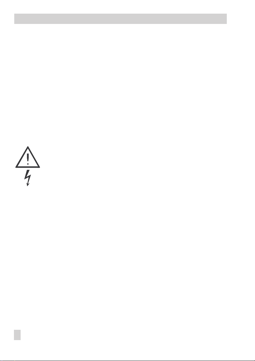
1.1 Control knob
Turn q:
*
Select parameters, displays and temperature displays
Press :
Confirm adjusted selection or settings
Press for three seconds 3s:
Switch from the operating level to the user level as well as from
the user level to the installation level
1.2 Operating modes
Automatic mode
Display: and in the time-of-use periods, and outside of the times-of-use periods
The controller works in rated operation within the programmed times-of-uses and in reduced
operation outside of the times-of-use, provided that the control operation is not deactivated
due to the outdoor temperature. The controller switches automatically between both operating modes.
Day mode (constant rated operation)
Display:
Regardless of the programmed times-of-use, the set points relevant for rated operation are
used constantly by the controller.
Stand-by mode (vacation mode)
Display:
In stand-by mode, the heating is switched off regardless of the programmed times-of-use.
The frost protection mode is still active.
Night mode (reduced operation; can only be set over the room panel)
Display:
Regardless of the programmed times-of-use, the set points relevant for reduced operation are
used constantly by the controller.
PArTY
HoLidAY
or
or – – –
EB 5432 EN 5
Page 6
Operation
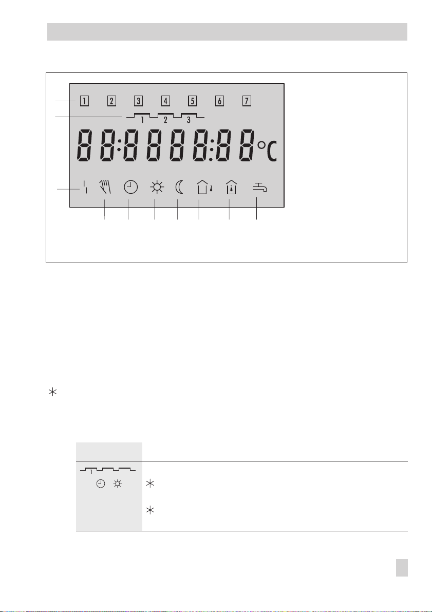
1.3 Display
The current set point appears on the display during operation.
Which set point is displayed depends on:
The configured type of control
4
The programmed times-of-use
4
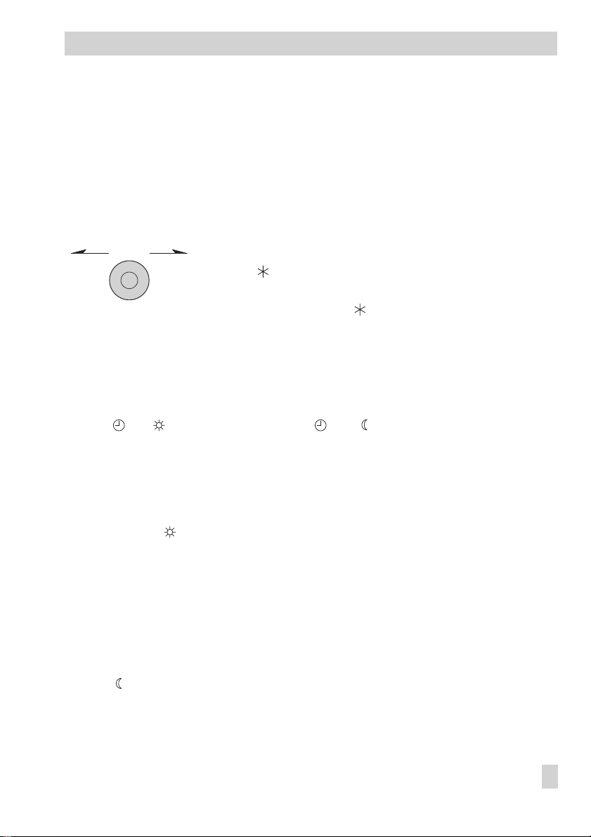
Weather-compensated control, room set point mode (F1 - 1 and F9 - 1)
Day set point (time-of-use period)*
or night set point (outside of time-of-use period)
Weather-compensated control (F1 - 1 and F9 - 0), fixed set point control (F1 - 0 and F7 - 0)
Flow temperature (times-of-use period)*
or reduced flow temperature (outside of time-of-use period)
The set point (left) and the measured value (right) are
displayed in this example.
* Appears on the depicted display
Note!
The icon appears additionally on the display for a control functioning with the room
panel unit (F7- 1).
A temporarily active set point (corrected once) is indicated on the display by the icon
together with the icon (refer to section 1.9.1).
An active function for drying of jointless floors is indicated on the display by the icon
together with the icon (refer to section 5.3).
6 EB 5432 EN
Page 7
Operation
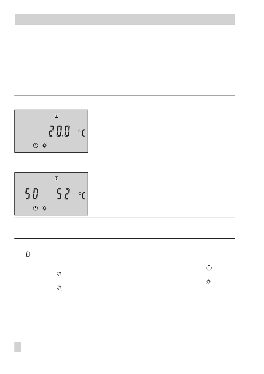
1 Days of week
1
2
3
4 5 6 7 8 9 10
Fig. 1 · Icons
Mon (1) to Sun (7)
2 Times-of-use
periods
3 Malfunction
4 Manual mode
5 Automatic mode
6 Day operation
(rated operation)
7 Night operation
(reduced operation)
8 Outdoor sensor
9 Room sensor
10 Hot water demand
1.4 Displaying data
The times-of-use periods, measured values as well as set points or limit values can be retrieved and displayed in the user level (–> Fig. 10 on page 49). The controller configuration
determines which measured values as well as which set points or limit values appear on the
display.
Proceed as follows:
3s Switch to user level.
Display: Time
q
Select value.
The different data points appear on the display in sequence:
Display Meaning
Current time-of-use
,
Open data point
q
Display daily times-of-use.
Confirm
Times-of-use
Times-of-use
appears on the display.
.
by pressing the knob when
End
EB 5432 EN 7
Page 8
Operation
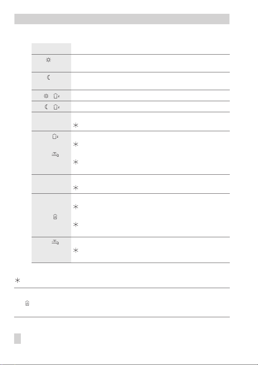
Display Meaning
* Day set point
* Night set point
or flow temperature set point (F1 - 0 and F7 - 0)
or reduced flow temperature set point (F1 - 0 and F7 - 0)
OT deactivating value in rated operation (F1 - 1 and F9 - 0)
OT deactivating value in reduced operation (F1 - 1 and F9 - 0)
t1
t2
,
t2
,
t3
t4
t4
,
t5
, Measured value: Storage tank temperature (F7 - 0)
q
Select
End
Switch to operating level.
Measured value: Flow temperature
Flow temperature set point
Measured value: Outdoor temperature
Delayed outdoor temperature (F3 - 1)
Measured value: Storage tank temperature (F1 - 0 and F7 - 1)
Activating/deactivating value for DHW system
(DHW set point + on/off differential)
Measured value: Return air temperature
Maximum return air temperature
Measured value: DHW temperature monitoring
Monitoring value
Measured value: Room temperature (F7 - 1)
Day set point or night set point
(influenced by a room panel, if applicable)
Activating/deactivating value for DHW system
(DHW set point + on/off differential)
on the display.
* Note!
The icon appears additionally on the display for a control functioning with the room
panel unit (F7- 1).
8 EB 5432 EN
Page 9
Operation
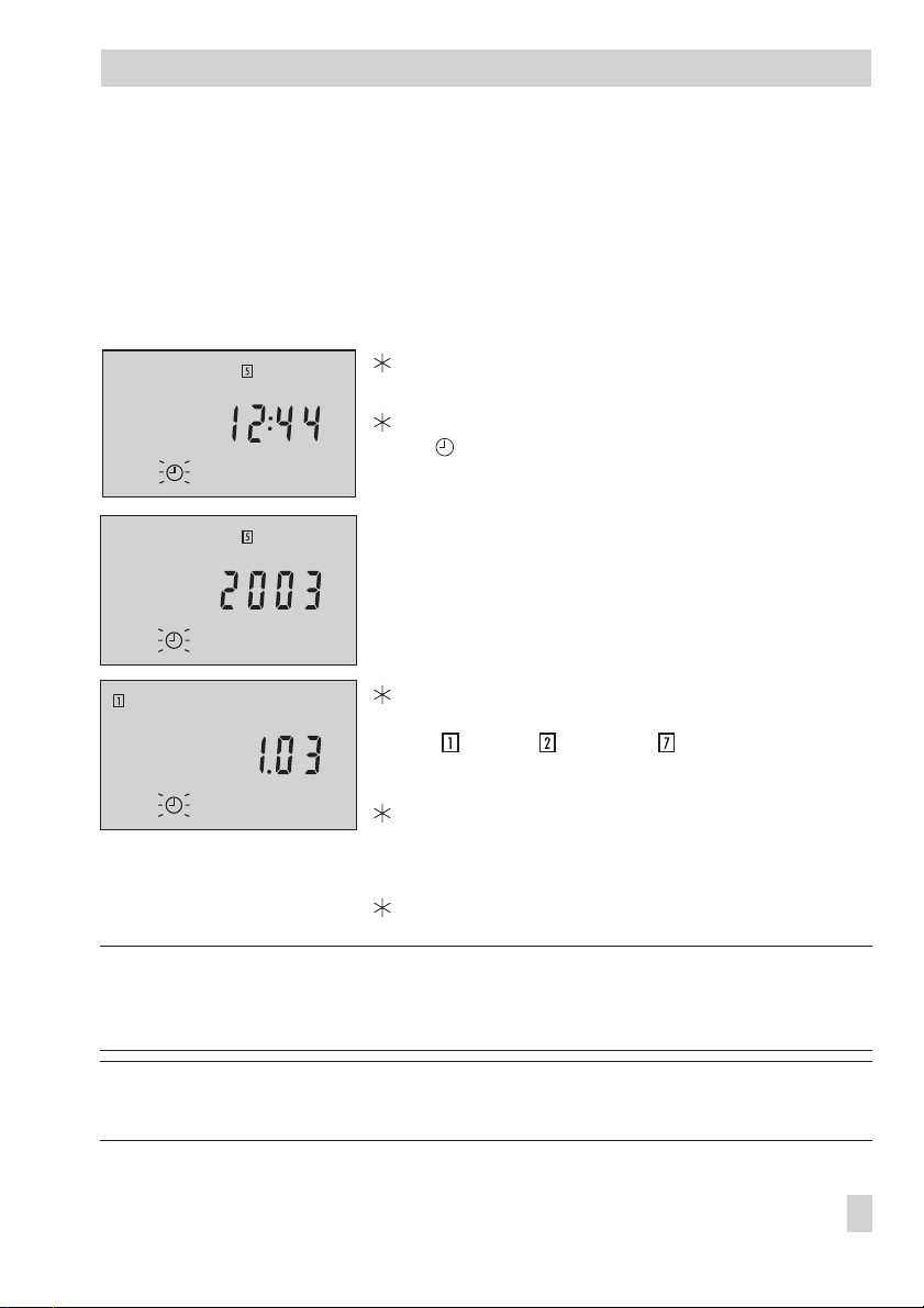
1.5 Setting the system time
The current time and date need to be set immediately after start-up and after a power failure
lasting more than 72 hours has occurred. This is indicated by the time blinking on the dis
play. The time is already in the edit mode and can be changed directly. The first two instruc
tions steps are then omitted.
Proceed as follows:
3s Switch to user level.
Display: Time.
Open time data point.
blinks.
Change time.
q
Confirm time setting.
Display: Year.
Change year.
q
Confirm year.
Display: Date (day.month) as well as day of the week
( = Mon, = Tue, …, = Sun)
q
Change date.
Confirm date.
Display: Time
q
Select
End
on the display.
Switch to operating level.
-
-
Note! On initial start-up and after a power failure lasting more than 72 hours, the controller
switches automatically to the operating level after the date has been set and confirmed. The
last two steps are omitted.
Note! The controller automatically switches to the operating level if the control knob is left
untouched for five minutes.
EB 5432 EN 9
Page 10
Operation
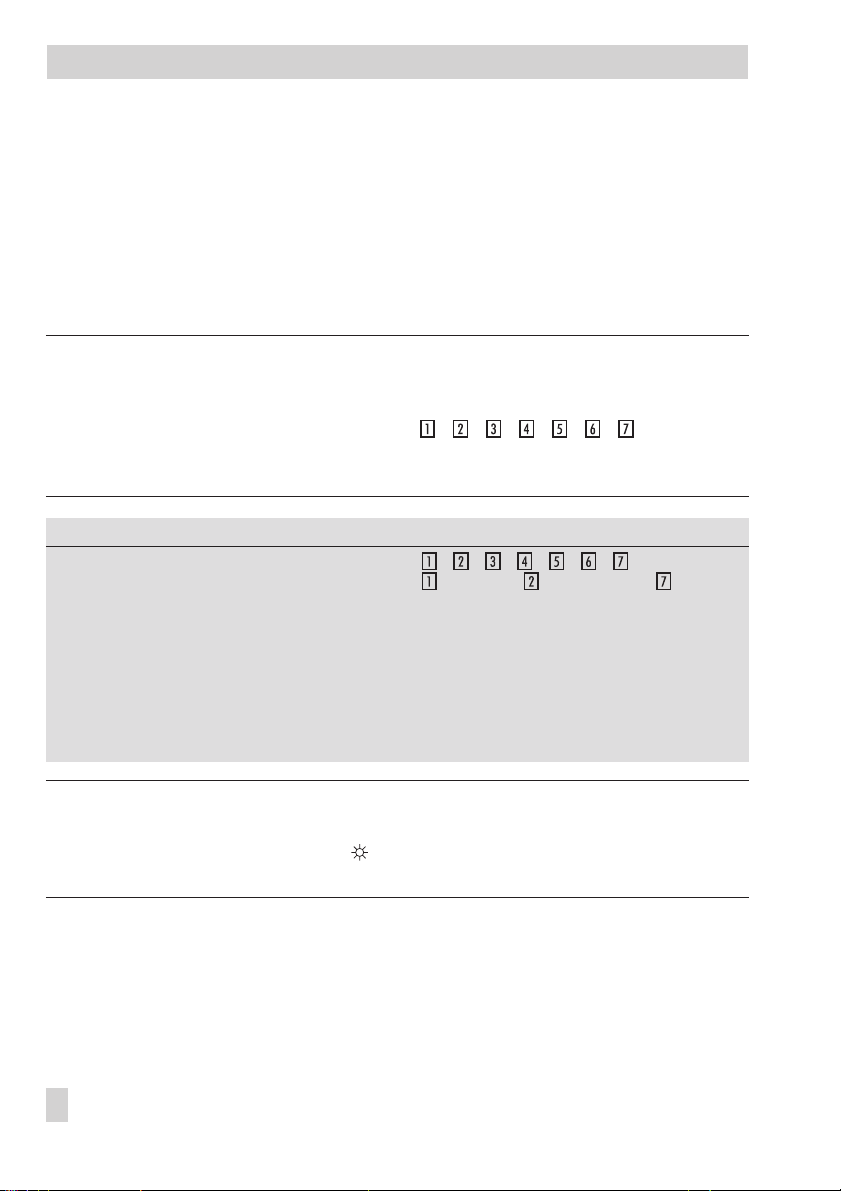
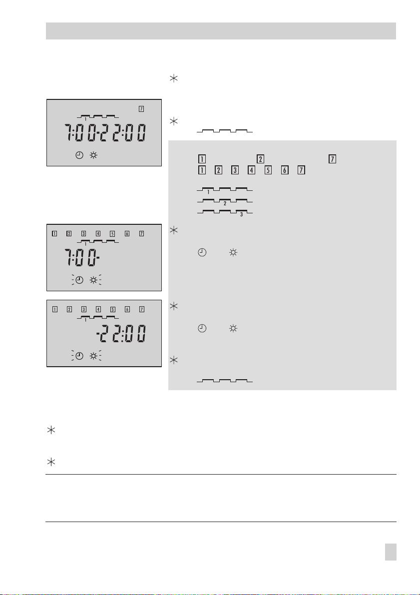
1.6 Setting the times-of-use
Three time-of-use periods can be set for each day of the week.
If not all the time-of-use periods are required, the start and stop times of the third time-of-use
period (for just two periods) must be set to identical times or, alternatively, the start and stop
times of the second time-of-use (for just one period). The controller then automatically sets the
start and stop times to the stop time of the previous time-of-use period.
The times-of-use are displayed in the user level (–> Fig. 10 on page 49).
Note!
You can set the times-of-use for each day or for an entire week. If you want to set the
times-of-use for certain days to be different than the rest of the week, we recommend you set
the times-of-use for the entire week first (display: ) and then al
ter the times-of-use for each day which require different times-of-use.
The week setting of the times-of-use writes over any already programmed times-of-use.
-
Parameter
Time period/day 1–7 = daily,
Start time of first time-of-use 07:00 00:00 to 24:00 h; in steps of 30 minutes
Stop time of first time-of-use 22:00 00:00 to 24:00 h; in steps of 30 minutes
Start time of second time-of-use 22:00 00:00 to 24:00 h; in steps of 30 minutes
Stop time of second time-of-use 22:00 00:00 to 24:00 h; in steps of 30 minutes
Start time of third time-of-use 22:00 00:00 to 24:00 h; in steps of 30 minutes
Stop time of third time-of-use 22:00 00:00 to 24:00 h; in steps of 30 minutes
WE Range of values
= Monday, = Tuesday, …, = Sunday
Note!
The controller includes an optimized activation function which makes sure the controller auto
matically changes to the valid set point ( blinks), six hours at the earliest before the pro
-
grammed time-of-use starts, to compensate for low outdoor temperatures.
10 EB 5432 EN
-
Page 11
Proceed as follows: 3s Switch to the user level.
Display: Time
Select
q
q
q
q
To set other times-of-use, repeat the instructions in the fields highlighted in gray.
q
Select
End
on the display.
Exit
Times-of-use
q
Select
End
Switch to operating level.
.
on the display.
Times-of-use
Open data point
Select time period/day and times-of-use:
= Monday, = Tuesday, …, = Sunday and
with
Open time period/day.
Display: Start time of first time-of-use period
and blink.
Change start time (in steps of 30 minutes).
Confirm start time.
Display: Stop time of first time-of-use period
and blink.
Change stop time.
Confirm stop time.
Display: Set time-of-use period
.
Times-of-use
blinks.
= first time-of-use period,
= second time-of-use period,
= third time-of-use period.
blinks.
.
= daily
Operation
Note!
The controller automatically switches to the operating level if the control knob is left un
touched for five minutes.
EB 5432 EN 11
-
Page 12
Operation
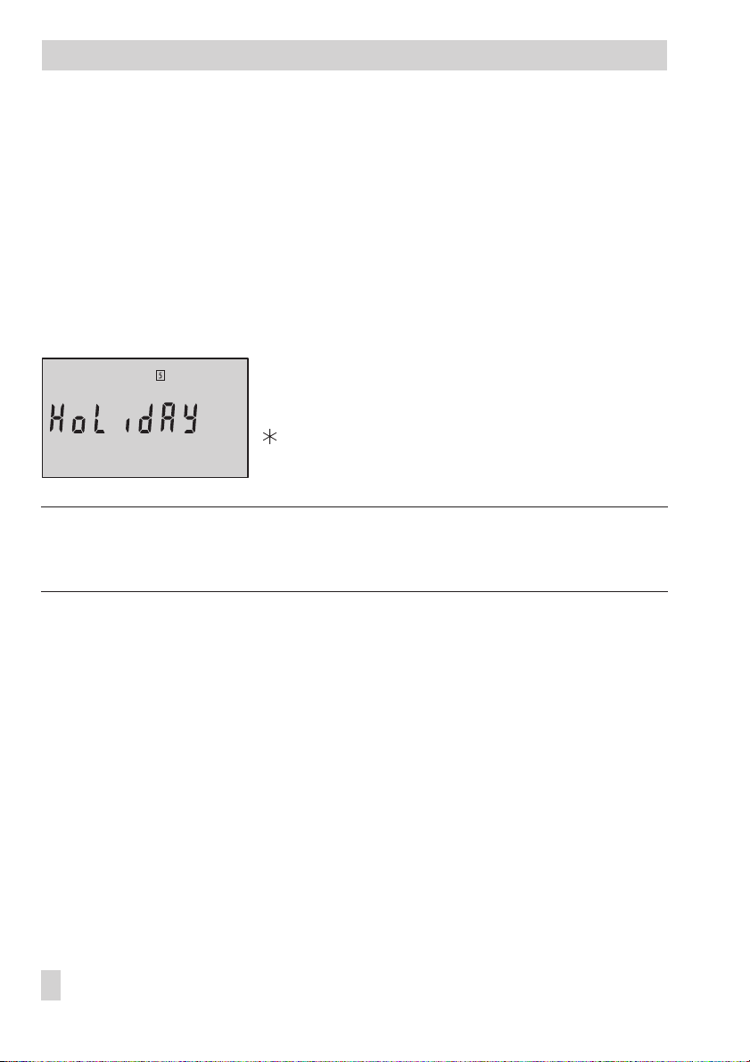
1.7 Stand-by mode
1.7.1 Vacation mode
Function independent of controller setting.
The vacation mode function places the heating circuit into the stand-by mode: the heating is
deactivated, however, frost protection is guaranteed. The functions of an existing DHW cir
cuit remain unchanged.
The vacation mode function is set in the operating level (set point display).
Proceed as follows:
Select menu
q
will go).
The display blinks.
Confirm vacation mode. Alternatively:
Wait 3 minutes until the display stops blinking.
The vacation mode is activated.
Note!
The controller is in vacation mode when HoLidAY appears on the display.
The controller exits the vacation mode when the current set point is reset (–> section 1.9).
HoLidAY
(turn knob to the left as far as it
-
1.7.2 Outdoor temperature dependent deactivation
Controller setting F1 - 1 and F9 - 1
The outdoor temperature dependent deactivation function places the heating circuit into the
stand-by mode dependent on the outdoor temperature. The heating is deactivated when the
outdoor temperature exceeds the active limit value (plus 1 °C on/off differential), however,
frost protection is still guaranteed. – – – appears on the display as the flow temperature set
point while the outdoor temperature dependent deactivation function is active. The functions
of an existing DHW circuit remain unchanged.
OT deactivating value in rated operation
The
value in reduced operation
12 EB 5432 EN
outside of the times-of-use apply and are set in the user level.
within the times-of-use and
OT deactivating
Page 13
Proceed as follows:
Vorgehen: 3s Switch to user level.
Display: Time.
Select
OT deactivating value in rated operation
OT deactivating value in reduced operation
Open data point.
Change data point.
Confirm data point.
Select
End
on the display.
Switch to operating level.
OT deactivating value in rated
operation
OT deactivating value in
reduced operation
q
q
q
Operation
or
.
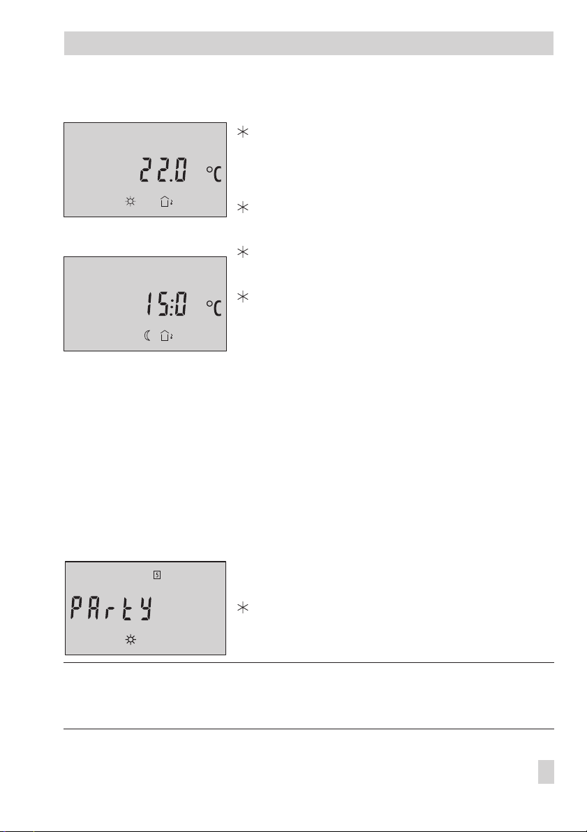
1.8 Party mode
Function independent of controller setting.
The party mode function sets the controller in rated operation mode: regardless of the pro-
grammed times-of-use, the
by the controller.
The party mode function is set in the operating level (set point display).
Proceed as follows:
Note!
The controller is in constant rated operation when PArtY appears on the display. The controller
exits the constant rated operation mode when the current set point is reset (–> section 1.9).
(constant rated operation)
Set point dayorFlow temperature set point
q
Select menu
will go). The display blinks.
Confirm party mode. Alternatively:
Wait 3 minutes until the display stops blinking.
The party mode is activated.
PArtY
(turn knob to the right as far as it
are constantly used
EB 5432 EN 13
Page 14

Operation
1.9 Correcting the set point
The current set point is displayed in the operating level. In rated operation, the
or the
Flow temperature set point
tion, the
Night set point
or the
appears on the display (–> section 1.3). In reduced opera
Reduced flow temperature set point
appears on the display.
Day set point
1.9.1 Correcting the set point temporarily
The current set point which appears on the display can be changed for just as long as the
rated operation mode (programmed time-of-use period) is running or the reduced operation
mode (outside of the time-of-use period) is running.
This temporary correction of the set point is made in the operating level (set point display).
Proceed as follows:
Turn the control knob one position.
q
The icon display blinks.
Change the parameter.
q
Confirm the new parameter setting. Alternatively:
Wait until the display stops blinking.
The new parameter setting has been saved.
The temporarily active set point (corrected once) is indicated on the display by the
icon together with the icon.
1.9.2 Correcting the set point permanently
The permanent change of
well as the
made in the user level.
Night set pointorReduced flow temperature set point
Day set pointorFlow temperature set point
in reduced operation is
in rated operation as
-
Proceed as follows:
3s Switch to user level. Display: Time
q
Select menu
Open the set point.
q
Change the set point.
Confirm the set point.
q
Select
Switch to operating level.
14 EB 5432 EN
Set point
End
on the display.
(–> page 6).
Page 15

Start-up
2 Start-up
2.1 Configuration and parameterization
The controller is configured and parameterized in the configuration and parameterization
level (–> Fig. 10 on page 49). After accessing the configuration and parameterization level
(CoPa level), the function blocks F1 to F9 appear at first, followed by the parameters P1 to
P18. The individual functions and parameters are listed in the Appendix (–> page 41).
The configuration and parameterization level is locked to prevent unintentional and unautho
rized access. This level can only be opened when the key number is known. The key number
can be found on page 48. To avoid unauthorized use of the key number, remove the page
or make the key number unreadable.
Proceed as follows:
3s Switch to user level. Display: Time
Select
End
q
3s Switch to the configuration and parameterization level (CoPa level).
Display: 0,
on the display.
nr
blinks.
q Set key number.
Confirm key number. Display: F1
q
Select function block* or parameter.
Open selected data point.
q
Change data point.
Confirm setting of the data point.
To set further function blocks and parameters, repeat the instructions in the fields highlighted
in gray.
q
Select
End
on the display.
Return to operating level.
Display: Current set point
-
* Note!
A function block is activated when F_ 1 appears on the display; it is deactivated when F_ 0
appears on the display.
EB 5432 EN 15
Page 16

Manual operation mode
3 Manual operation mode
In manual operation mode, the circulation pump UP is always switched on. The output SLP is
usually switched off. Initially, no control signal is issued for the heating circuit.
Activate the manual operation mode in the configuration and parameterization level (CoPa
level) over function block F2.
Functions
Manual operation of an actuator 0 F2 - 1
Proceed as follows:
3s Switch to user level.
Display: Time
Select
End
q
3s Switch to the configuration and parameterization level (CoPa level).
Display: 0,
Set key number.
q
Confirm key number.
Display: F1
q
Select function block F2.
Open function block F2.
q
Activate function block F2.
Display: F2 - 1.
Activate manual operation mode.
Display: and
q
Move the actuator manually:
oPEn: OPEN (3-step signal); activate output (on/off signal)
StoP: Last position (3-step signal); deactivate output (on/off signal)
cLoSE: CLOSED (3-step signal)
on the display.
nr
blinks.
StoP
WE Configuration
Note!
The frost protection function is not active in manual operation mode.
16 EB 5432 EN
Page 17

Manual operation mode
Exit manual operation mode:
Select cLoSE on the display.
q
3s Close manual operation mode and return to operating level.
Displaying measured values during manual operation mode
Select StoP on the display.
q
3s Switch to user level.
Display: Time
Select the measured values t1 to t5 in sequence.
q
Select
End
q
Switch to menu for moving actuator manually (oPEn, StoP or cLoSE).
Note!
The manual operation mode is maintained even after a power failure (display: StoP).
on the display.
EB 5432 EN 17
Page 18

Systems
4 Systems
The heating system can be designed either as a primary system, secondary system or a sin
gle-stage boiler system.
The flow temperature can either be controlled weather-compensated, based on the room
temperature or a fixed set point. The hydraulic schematics of the heating system and the con
troller configuration are the factors that determine how the flow temperature is controlled.
Primary system, indirect Primary system, direct
S3 S1UPHK_3-step S4
BE
BA
AE
RK
BE
BA
AE
RK
Secondary system Boiler system
Single-stage
boiler
S1UP S3HK_3-step S4 S2S2
-
-
BE
BA
AE
RK
18 EB 5432 EN
S2 S2
S3S1UP HK_3-step S4
BE
BA
AE
RK
UPHK_on/off S4S1
Page 19

Weather-compensated control without room panel (= default setting)
Setting F1 - 1 (with outdoor temperature sensor S2)
F7 - 0 (without room panel)
Comments With or without S3 (depending on the circuit)
F4 - 0 for single-stage boiler system
Storage tank charging/DHW priority possible (–> Figs. 2 and 3)
Weather-compensated control with room panel
Setting F1 - 1 (with outdoor temperature sensor S2)
F7 - 1 (with room panel)
Comments With or without S3 (depending on the circuit)
F4 - 0 for single-stage boiler system
Storage tank charging/DHW priority not possible
Fixed set point control
Setting F1 - 0 (without outdoor temperature sensor S2)
F7 - 0 (without room panel)
Comments With or without S3 (depending on the circuit)
F4 - 0 for single-stage boiler system
Storage tank charging/DHW priority possible (–> Figs. 2 and 3)
Room temperature-based control
Setting F1 - 0 (without outdoor temperature sensor AS)
F7 - 1 (with room panel)
Comments With or without S3 (depending on the circuit)
F4 - 0 for single-stage boiler system
Storage tank charging/DHW priority possible (–> Fig. 4)
Systems
EB 5432 EN 19
Page 20

Systems
WW
KW
HK_3-step
S3 S1
BE
BA
AE
RK
UP
S5
Fig. 2 · Weather-compensated control or fixed set point control and on/off control for storage tank
system in the primary circuit
Weather-compensated control Fixed set point control
Setting
Comments
F1 - 1 and F7 - 0 F1 - 0 and F7 - 0
With or without S3 (depending on the circuit)
Storage tank charging over storage tank sensor S5
(depending on the circuit)
Monitoring priority at S5
S2TW_on/off
20 EB 5432 EN
Page 21

Systems
WW
KW
BE
BA
AE
RK
HK_3-step
ROH
UP
S3 S1 S4
Fig. 3 · Weather-compensated control or fixed set point control and mechanical control (ROH =
self-operated regulators) for storage tank system in the primary circuit
Weather-compensated control Fixed set point control
Setting
Comments
F1 - 1 and F7 - 0 F1 - 0 and F7 - 0
With or without S3 (depending on the circuit)
Storage tank charging over storage tank sensor S5
(depending on the circuit)
Monitoring priority at S4 (depending on the circuit) or S5
S2SLP
S5
EB 5432 EN 21
Page 22

Systems
WW
KW
BE
BA
AE
RK
HK_3-step
UP
S3 S1
S4
TW_on/off
S2
Fig. 4 · Room temperature-based control and on/off control of the storage tank system in the primary
system
Room temperature-based control
Setting
Comments
With or without S3 (depending on the circuit)
F1 - 0 and F7 - 1
Storage tank charging over storage tank sensor S2
(depending on the circuit)
Monitoring priority at S2
22 EB 5432 EN
Page 23

Functions of the heating circuit
5 Functions of the heating circuit
5.1 Weather-compensated control
When weather-compensated control is used, the flow temperature is adjusted according to
the outdoor temperature. The heating characteristic in the controller defines the flow temper
ature set point as a function of the outdoor temperature (–> Fig. 5).
t
[˚C]
VL
130
120
110
100
90
80
70
60
50
40
30
20
Fig. 5 Gradient characteristics
2.62.93.2
2.4
2.2
2.0
1.8
1.6
1.4
t
1.2
1.0
0.8
0.6
0.4
0.2
-16-12-8-4048121620
-20 [
VL
t
A
t
A
C]
˚
Flow temperature
Outdoor temperature
-
Basically, the following rule applies: a drop in outdoor temperature causes the flow tempera
ture to rise. By varying the parameters
Gradient
your individual requirements. Increasing
creasing
Gradient
in a lower flow temperature. The parameter
and
Gradient
Level
, you can adapt the characteristic to
results in a higher flow temperature, de
Level
performs a parallel
shifting of the heating characteristic in upward or downward direction.
Outside the times-of-use, reduced set points are used for control:
The reduced flow set point is calculated either as the difference between the adjusted values
Day set point
for
or dependent on the parameter P9
(rated room temperature) and
(Set-back of flow temperature in reduced operation)
Night set point
(reduced room temperature)
with
the controller setting F1 - 1 and F9 - 0.
The parameters
Max. flow temperature
and
Min. flow temperature
mark the upper and lower
limits of the flow temperature.
EB 5432 EN 23
-
-
Page 24

Functions of the heating circuit
Examples for setting the characteristic:
Old building, radiator design 90/70: Gradient approx. 1.8
4
New building, radiator design 70/55: Gradient approx. 1.4
4
New building, radiator design 55/45: Gradient approx. 1.0
4
Underfloor heating depending on arrangement: Gradient smaller 0.5
4
Weather-compensated control, room set point mode
Functions
Type of control 1 F1 - 1
Room set point mode 1 F9 - 1
Parameter
Day set point 20 °C User level / 10 to 40 °C
Night set point 15 °C User level / 10 to 40 °C
Gradient 1.6
Level 0 °C
Min. flow temperature 30 °C
Max. flow temperature 80 °C
WE Configuration
WE Level / Range of values
CoPa level P1 / 0.2 to 3.2
CoPa level P2 / –30 to 30 °C
CoPa level P3 / 0 to 130 °C
CoPa level P4 / 0 to 130 °C
Weather-compensated control
Functions
Type of control 1 F1 - 1
Room set point mode 1 F9 - 0
Parameter
OT deactivating value in rated operation 22 °C User level / 0 to 50 °C
OT deactivating value in reduced operation 15 °C User level / –30 to 50 °C
Gradient 1.6
Level 0 °C
Min. flow temperature 30 °C
Max. flow temperature 80 °C
Set-back of flow temperature in reduced operation 15 °C
WE Configuration
WE Level / Range of values
CoPa level P1 / 0.2 to 3.2
CoPa level P2 / –30 to 30 °C
CoPa level P3 / 0 to 130 °C
CoPa level P4 / 0 to 130 °C
CoPa level P9 / 0 to 50 °C
24 EB 5432 EN
Page 25

Functions of the heating circuit
Note!
Particularly for control operation without room panel, the room temperatures for day
set point)
and night
(Night set point)
adjusted in the room set point mode only become effec
(Day
tive satisfactorily when the heating characteristic has been adapted to the building/heating
surface layout.
5.2 Fixed set point control
During a time-of-use period, the flow temperature can be controlled according to a fixed set
point. Outside the time-of-use periods, the controller regulates the reduced flow temperature.
-
Functions
Type of control 1 F1 - 0
Parameter
Flow temperature set point 50 °C User level / 0 to 130 °C
Reduced flow temperature set point 30 °C User level / 0 to 130 °C
WE Configuration
WE Level / Range of values
5.3 Drying of jointless floors
In compliance with Part 4 of the DIN EN 1264 standard, the first heating up is performed
with a flow temperature of 25 °C. This temperature is maintained constant for 3 days. After
that, the controller uses the maximum flow temperature as the set point for the following
4 days. When the drying of jointless floors function is activated, the set point appears on the
left-hand side of the display and the current flow temperature appears on the right-hand side
of the display.
An active function for drying of jointless floors is indicated on the display by the icon to
gether with the icon.
The function is switched off automatically when the drying is completed.
Note!
A power failure or any change in the controller setting resets the drying function to restart .
Function
Drying of jointless floors 0 F6 - 1
WE Configuration
-
EB 5432 EN 25
Page 26

Functions of the heating circuit
5.4 Automatic deactivation of the heating
The heating is automatically deactivated according to various criteria depending on whether
the heating system is equipped with or without a room panel:
Weather-compensated control, room set point mode (F1 - 1 and F9 - 1) – without room panel
Deactivation during day mode The outdoor temperature exceeds the
Deactivation during night
mode
Weather-compensated control (F1 - 1 and F9 - 0) – without room panel
Deactivation during day
mode
Deactivation during night
mode
Weather-compensated control (F1 - 1 and F7 - 1) – with room panel
Deactivation during day mode The outdoor temperature exceeds the
Deactivation during night
operating mode
Room temperature-based control
Deactivation during day mode The room temperature exceeds the
Deactivation during night
operating mode
The outdoor temperature exceeds the
The outdoor temperature exceeds
operation
The outdoor temperature exceeds
operation
The
exceeds the
The
exceeds the
The room temperature exceeds the
by 1 °C.
by 1 °C.
Night set point
Night set point
Night set point
Night set point
is 17 °C or higher and the outdoor temperature
by 1 °C.
is 17 °C or lower and the room temperature
by 1 °C.
Day set point
Night set point
OT deactivating value in rated
OT deactivating value in reduced
Day set point
Day set point
Night set point
by 1 °C.
by 1 °C.
by 1 °C.
by 1 °C.
by 1 °C.
The heating is activated immediately when the temperature falls below the relevant set point.
Note!
The table does not include any specifications for fixed set point control as the heating is
never deactivated with this type of control.
26 EB 5432 EN
Page 27

Functions of the heating circuit
5.5 Outdoor temperature dependent advance heating
Due to low outdoor temperatures, the controller starts heating before the time-of-use period
starts in rated operation. The
Advance heating time
–12 °C. The advance heating time is shortened when the outdoor temperature is higher.
The colder it is outside, the earlier the reduced operation is ended to ensure that the required
room temperature is reached at the start of the time-of-use period.
Note! During the advance heating phase, the icon blinks on the display.
uses a reference outdoor temperature of
Functions
Type of control 1 F1 - 1
Parameter
Advance heating time 120 min
WE Configuration
WE Level / Range of values
CoPa level P17 / 0 to 360 min
5.6 Delayed adaptation to the outdoor temperature
The calculated outdoor temperature is used to determine the flow temperature set point. The
heat response is delayed when the outdoor temperature either gets colder or warmer. If the
outdoor temperature varies by, for example, 10 °C within a very short period of time, the
calculated outdoor temperature is adapted to the actual outdoor temperature in small steps.
Delay
Assuming a
of 5 °C/h, the adaptation would take
The delayed adaptation to the outdoor temperature helps avoid unnecessary overloads of
central heating stations in combination with either overheated buildings occurring, for exam
ple, due to warm winds, or temporarily insufficient heating due to the outdoor sensor being
exposed to direct sunshine.
Note!
The described function can only be activated together with weather-compensated control.
Functions
Type of control 1 F1 - 1
Delayed adaptation to outdoor temperature 0 F3 - 1
Parameter
Delay 3 °C/h
WE Configuration
WE Level / Range of values
CoPa level P7 / 1 to 6 °C/h
C
°°10
/
Ch
.
2
th
==
5
-
EB 5432 EN 27
Page 28

Functions of the heating circuit
5.7 Remote control
Apart from measuring the room temperature, the Type 5257-5 Room Panel (Pt 1000 sensor)
provides the following opportunities of influencing the control process:
Selection of the operating mode: – Automatic mode
4
Set point correction: during rated operation, the room temperature set point can be in
4
creased or reduced by up to 5 °C using a continuously adjustable rotary knob
When the remote room controller (room panel) is connected and activated, the corrected
Room temperature set point
Functions
Room panel 0 F7 - 1
is shown.
– Rated operation (day)
– Reduced operation (night)
WE Configuration
5.8 Flash adaptation
A Type 5257-5 Room Panel must be connected for the Flash adaptation function.
The flash adaptation counteracts deviations in room temperature by reducing or raising the
flow temperature by up to 30 °C. The
tion of the flow temperature set point by 1 °C.
The flash adaptation is deactivated when the parameter
measured room temperature then does not have any affect on the flow temperature control.
Cycle rate
determines the time between each correc-
Cycle rate
(P18) is set to 0. The
-
Note!
We recommend setting the flash adaptation initially with a cycle rate of 10 minutes. Shorter
cycle rates are more likely to have a negative effect, particularly when cooling loads such as
drafts or an open window affect the control. Then the rooms may be temporarily overheated
when the cooling load is eliminated.
Functions
Type of control 1 F1 - 1
Room panel 0 F7 - 1
Parameter
Cycle rate 0 min
28 EB 5432 EN
WE Configuration
WE Level / Range of values
CoPa level P18 / 0 to 100 min
Page 29

Functions of the heating circuit
5.9 Room temperature-based control
A Type 5257-5 Room Panel must be connected for the Room temperature-based control
function; however, the control works without an outdoor sensor.
The flow temperature is reduced or raised by up to 30 °C when deviations in room tempera
ture occur. The
Cycle rate
ture set point by 1 °C. The default setting is 10 minutes when the room temperature-based
control is activated; the flow temperature control starts with a default set point of 50 °C, pro
vided that the parameter
Note!
We recommend not to set the cycle rate too short. Shorter cycle rates are more likely to have
a negative effect, particularly when cooling loads such as drafts or an open window affect
the control. Then the rooms may be temporarily overheated when the cooling load is elimi
nated.
determines the time between each correction of the flow tempera
Max. flow temperature
(P4) permits it.
-
-
-
-
Functions
Type of control 1 F1 - 0
Room panel 0 F7 - 1
Parameter
Cycle rate 10 min
WE Configuration
WE Level / Range of values
CoPa level P18 / 1 to 100 min
EB 5432 EN 29
Page 30

Functions of the DHW circuit
6 Functions of the DHW circuit
a) b)
Fig. 6 · DHW system in a storage tank charging system (a) and in a storage tank system (b)
The controller starts charging the storage tank as soon as the water temperature measured
at the storage tank sensor (S5 or S2) falls below the
The charging of the storage tank finishes when the water temperature measured at the storage tank sensor has reached the temperature T =
storage tank charging.
Use F8 to select the
F8 - 0: On/off differential = 5 °C
4
F8 - 1: On/off differential = 2 °C
4
Functions
On/off differential of storage tank charging 0 F8
Parameter
DHW set point 45 °C
On/off differential of storage tank charging
WE Configuration
WE Level / Range of values
DHW set point
DHW set point+On/off differential of
CoPa level P16 / 20 to 90 °C
(P16).
.
6.1 DHW priority
Should the temperature at the DHW sensor S4 or, in cases where DHW sensor S4 does not
exist, at the storage tank sensor S5/S2, fall below the
minutes, the heating capacity of the heating circuit is lowered by reducing the set point. The
heating circuit set point is then reduced in small steps every five minutes up to a minimum
30 EB 5432 EN
Monitoring value for priority
for five
Page 31

Functions of the DHW circuit
flow temperature of 20 °C, provided the temperature still lies below the
priority.
Three different operating conditions exist:
The DHW temperature at S4 (S5/S2) is under the
4
heating circuit set point is reduced.
The DHW temperature to S4 (S5/S2) is up to 5 °C above the
4
4
Functions
Room panel 0 F7 *
* F7 - 0: Monitoring value for priority at S4 (depending on the circuit) or storage tank
Parameter
Monitoring value for priority 40 °C
the heating circuit set point remains unchanged.
ity –>
The DHW temperature to S4 (S5/S2) exceeds the
than 5 °C –> the heating circuit set point which was reduced due to the priority is in
creased.
WE Configuration
charging and
Monitoring value for priority at S5
F7 - 1: Storage tank charging and monitoring value for priority at S2 (room
temperature-based control)
WE Level / Range of values
Monitoring value for priority –>
Monitoring value for priority
CoPa level P6 / 20 to 90 °C
Monitoring value for
Monitoring value for prior
the
-
by more
-
EB 5432 EN 31
Page 32

System-wide functions
7 System-wide functions
7.1 Automatic summer time/winter time changeover
The clock is automatically set one hour forward on the last Sunday in March at 2.00 h and
set one hour back on the last Sunday in October at 3.00 h.
Function
Summer time/winter time changeover 1 F5 - 1
WE Configuration
7.2 Frost protection
The frost protection function is activated with weather-compensated or room temperaturebased control.
The circulation pump is activated and a flow set point of 20 °C is used for the control when
the outdoor temperature is lower than 3 °C with weather-compensated control and the heating is switched off (stand-by mode).
The flow temperature is monitored with room temperature-based control and the heating is
switched off. If the flow temperature drops below 5 °C, the circulation pump is activated and
the flow temperature set point of 20 °C is used for the control.
Note!
The frost protection function is not active in manual operating mode or with fixed set point
control.
7.3 Forced operation of the pumps
When the circulation pumps have not been activated for 24 hours, forced operation of the
pumps is started at 12.00 h for one minute to prevent the pumps from getting stuck when
they are not operated for a longer period of time.
32 EB 5432 EN
Page 33

System-wide functions
7.4 Limiting the return flow temperature
The temperature difference between the flow and return flow in a network indicates how well
the energy is used: the greater the difference, the higher the efficiency. A return flow sensor
is sufficient to evaluate the temperature difference when the network flow temperatures are
predetermined. The flow temperature set point is reduced when the return flow temperature
measured at the return flow sensor S3 exceeds the limit temperature. As a result, the primary
flow rate is reduced and the return flow temperature falls. A PI algorithm is used to limit the
return flow temperature. The integral action cannot be parameterized.
Parameter
Maximum return flow temperature 50 °C
KPReturn flow temperature limit 1.0
WE Level / Range of values
CoPa level P5 / 20 to 90 °C
CoPa level P8 / 0.1 to 50.0
7.5 Three-step control
The flow temperature can be controlled with a PI algorithm. The motorized valve reacts to
pulses which the controller issues when a system deviation arises. In particular, the length of
the first pulse depends on the size of the system deviation and the selected
(the impulse length increases as the KPincreases). The intervals between each pulse and
gain
the interval length between pulses change continuously until the system deviation has been
eliminated.
The interval length between each pulse is greatly influenced by the
length increases as T
increases). The
N
Valve transit time T
specifies the time required by the
Y
valve to travel through the range from 0 to 100 %.
Functions
Control signal 1 F4 - 1
Parameter
KP(proportional gain) 2.0
TN(reset time) 120 s
TY(valve transit time) 45 s
WE Configuration
WE Level / Range of values
CoPa level P10 / 0.1 to 50.0
CoPa level P11 / 0 to 999 s
CoPa level P12 / 10 to 240 s
KPProportional
Reset time T
(the interval
N
EB 5432 EN 33
Page 34

System-wide functions
7.6 On/off control
The flow temperature can be controlled, for instance, by switching a burner on and off. The
burner is switched on by the controller when the flow temperature falls below the set point
T = 0.5 x
On/off differential
the burner is switched off again. The larger the
of switching involved. The default setting of
it is switched on to run permanently for this time regardless of how long. Likewise, a burner
that has just been switched off due to the temperature conditions when the programmed
imum activation time
Functions
Control signal 1 F4 - 0
Parameter
On/off differential 5 °C
Min. activation time 120 s
Min. deactivation time 120 s
. On exceeding the set point by T = 0.5 x
On/off differential
Minimum activation time
On/off differential
selected, the less amount
enables a burner once
remains switched off regardless how long for the time set.
WE Configuration
WE Level / Range of values
CoPa level P13 / 2 to 10 °C
CoPa level P14 / 0 to 600 s
CoPa level P15 / 0 to 600 s
,
Min
-
34 EB 5432 EN
Page 35

8 Malfunctions
Malfunctions
The controller’s reaction when a sensor is defective or a sensor is missing is described in fol
lowing:
Flow sensor:
4
For three-step control, the control valve takes on the valve position 30 %.
For on/off control, the controller regulates the on/off output at 30-minute intervals as
long as the time set under
The icon blinks on the display when the sensor fails.
Outdoor sensor:
4
A flow temperature set point of 50 °C is used for control, or the
is used if the maximum flow temperature (P4) is lower than 50 °C.
ture
The icon blinks on the display when the sensor fails.
Return flow sensor:
4
The return flow temperature limit function is deactivated.
Room sensor in room panel:
4
The flow temperature control is no longer affected by the measured room temperature.
The icon blinks on the display when the sensor fails.
DHW sensor:
4
The monitoring of priority changes to storage tank sensor, if necessary.
Storage tank sensor:
4
There is no storage tank charging.
Minimum activation time
(P14).
Maximum flow tempera
-
-
EB 5432 EN 35
Page 36

Infrared interface
9 Infrared interface
The TROVIS 5432 Heating and District Heating Controller can be configured and operated
over the front infrared interface using SAMSON’s TROVIS-VIEW Operator Interface soft
ware. This software’s operation is similar to Microsoft Windows Explorer.
The TROVIS-VIEW software is supplied with the device-specific module for the TROVIS 5432
Heating and District Heating Controller on CD-ROM (order no. 6661-1002).
The minimum system requirements can be found in the Data Sheet T 6661 EN for
TROVIS-VIEW as well as the readme.txt file in the main directory of the CD-ROM.
An infrared interface on the controller front panel is used for communication between PC
and controller. Data transmission between the RS-232 serial port on a PC and the integrated
controller infrared interface requires an infrared adapter (order no. 8864-0900).
-
2
1
Fig. 7 · Data transfer over the infrared interface
36 EB 5432 EN
0.7 m
˚
25
1 Infrared adapter
2 Connect to PC at optionally
COM1 to COM4 ports
Page 37

10 Installation
Installation
The controller consists of the housing section and base. The housing section contains the en
tire electronics, the display as well as the control knob. The base contains the terminal strip.
The controller is suitable for mounting in control panels or on walls (–> Fig. 8).
Note!
An adapter is available to mount the controller on top-hat rails.
Control panel mounting
1. Press down the tongue on top of the controller.
2. Tip the housing forward and remove it from the base.
3. Make a cut-out of 138 x 92 mm (W x H) in the control panel.
4. Insert the controller housing through the panel cut-out.
5. Use the two threaded bolts located at the side of the housing and the clips to clamp the
housing in the panel.
6. Install the electrical connections in the base as described in section 11.
7. First attach the lower part of the base to the housing and then snap on the top part.
Wall mounting
1. Press down the tongue on top of the controller.
2. Tip the housing forward and remove it from the base.
3. If necessary, drill holes at the intended place using the specifications given. Fasten
base with screws.
4. Install the electrical connections in the base as described in section 11.
5. First attach the lower part of the base to the housing and then snap on the top part.
-
EB 5432 EN 37
Page 38

Installation
96
15
Holes for
adapter to
mount on
top-hat rail
Fig. 8 · Installation
140
5044.3
22
3
35
15
29.3
55.5
91
10
137
8
38 EB 5432 EN
Page 39

Electrical connection
11 Electrical connection
!
Caution!
For electrical installation, you are required to observe the relevant electrotechnical regula
tions of the country of use as well as the regulations of the local power suppliers. Make sure
all electrical connections are installed by trained and experienced personnel!
Notes on installing the electrical connections
-
Install the 230 V power supply lines and the signal lines separately! To increase noise im
4
munity, observe a minimum distance of 10 cm between the lines. Make sure the minimum
distance is also observed when the lines are installed in a cabinet.
The lines for digital signals (bus lines) and analog signals (sensor lines, analog outputs)
4
must also be installed separately!
In plants with a high electromagnetic noise level, we recommend to use shielded cables
4
for the analog signal lines. Ground the shield at one side, either at the control cabinet inlet or outlet, using the largest possible cross-section. Connect the central grounding point
and the PE grounding conductor with a cable≥10 mm² using the shortest route.
Inductances in the control cabinet, e.g. contactor coils, are to be equipped with suitable
4
interference suppressors (RC elements).
Control cabinet elements with high field strength, e.g. transformers or frequency convert-
4
ers, should be shielded with separators providing a good ground connection.
Overvoltage protection
If signal lines are installed outside buildings or over large distances, make sure appropri
4
ate surge or overvoltage protection measures are taken. Such measures are indispens
able for bus lines!
The shield of signal lines installed outside buildings must have current conducting capac
4
ity and must be grounded on both sides.
Surge diverters must be installed at the control cabinet inlet.
4
Connecting the controller
The controller is connected as illustrated in the wiring diagram.
Open the housing to connect the cables. To connect the feeding cables, make holes in the
marked locations underneath on the base and fit suitable grommets or cable glands.
-
-
-
-
Connecting the sensors
Cables with a minimum cross-section of 2 x 0.5 mm² can be connected to the terminals at
the controller base unit.
EB 5432 EN 39
Page 40

Electrical connection
Note!
The controller can only be operated with Pt 1000 sensors.
Connecting the actuators
Connect cables with at least 1.5 mm² suitable for damp locations to the terminals of the con
troller output. The direction of travel needs to be checked at start-up (–> section 3).
Connecting the pumps
Connect all cables with at least 1.5 mm² to the terminals of the controller as illustrated in the
connection diagram.
-
12345678910
NL
UP SLP HK_3-step
56 89
TW_on/off HK_on/off
+
_
Fig. 9 · Electrical connection
40 EB 5432 EN
11 12
13
14 15 16 17 18
S4 S5S3S2S1
16 17 18
Type 5257-5
123
Room Panel
Page 41

Appendix
12 Appendix
12.1 Function block list
F Function WE Comments
F1 Type of control 1 F1 - 1: Weather-compensated control
F1 - 0: Fixed set point control or
F1 - 0 and F7 - 1: Room temperature-based control
F2 Manual operation of
actuator
F3 Delayed adaptation to
outdoor temperature
F4 Control signal 1 F4 - 1: 3-step control
F5 Summer time/winter time
changeover
F6 Drying of jointless floors 0 F6 - 1: Drying of jointless floors active
F7 Room panel 0 F7 - 1: Connection of Type 5257-5 Room Panel to S4/S5
F8 On/off differential of
storage tank charging
F9 Room set point mode 1 Only effective with F1 - 1:
F Function block, WE default setting
0 F2 - 1: Manual operation mode active
0 F3 - 1: Delayed adaptation to outdoor temperature,
only effective with F1 - 1
F4 - 0: On/off control
1 F5 - 1: Changeover active
After the function’s running time has elapsed, F6 - 0 is set.
F7 - 0: DHW priority, storage tank charging over S4/S5
(depending on circuit)
0 F8 - 1: On/off differential = 2 °C
F8 - 0: On/off differential = 5 °C
F9 - 1: Room set point assignable
F9 - 0: Set-back and outdoor temperature dependent
deactivating values assignable
EB 5432 EN 41
Page 42

Appendix
12.2 Parameter list
P Designation WE Range of value
P1 Gradient 1.6 0.2 to 3.2
P2 Level 0 °C –30 to 30 °C
P3 Min. flow temperature 30 °C 0 to 130 °C
P4 Max. flow temperature 80 °C 0 to 130 °C
P5 Max. return flow
temperature
P6 Monitoring value for priority 40 °C 20 to 90 °C
P7 Delay 3 °C/h 1 to 6 °C/h
P8 KPReturn flow temperature
limit
P9 Set-back of flow tempera-
ture in reduced operation
P10 KPThree-step control 2.0 0.1 to 50.0
P11 TNThree-step control 120 s 0 to 999 s
P12 TYThree-step control 45 s 10 to 240 s
P13 On/off differential
P14 Min. activation time for
on/off control
P15 Min. deactivation time for
on/off control
P16 DHW set point 45 °C 20 to 90 °C
P17 Advance heating time 120 min 0 to 360 min
P18 Cycle rate 0 min
P Parameter, WE Default setting
50 °C
1.0
15 °C
5 °C
120 s
120 s
and
10 min
20 to 90 °C
0.1 to 50.0
0 to 50 °C
2 to 10 °C
0 to 600 s
0 to 600 s
01to 100 min/
to 100 min
42 EB 5432 EN
Page 43

Appendix
12.3 Resistance values with Pt 1000 sensor
°C –35 –30 –25 –20 –15 –10 –5 0 5 10
862.5 882.2 901.9 921.6 941.2 960.9 980.4 1000.0 1019.5 1039.0
Ω
°C 15 20 25 30 35 40 45 50 55 60
1058.5 1077.9 1097.3 1116.7 1136.1 1155.4 1174.7 1194.0 1213.2 1232.4
Ω
°C 65 70 75 80 85 90 95 100 105 110
1251.6 1270.7 1289.8 1308.9 1328.0 1347.0 1366.0 1385.0 1403.9 1422.9
Ω
°C 115 120 125 130 135 140 145 150
1441.7 1460.6 1479.4 1498.2 1517.0 1535.8 1554.5 1573.1
Ω
12.4 Technical data
Inputs 5 inputs for Pt 1000 sensors
Outputs
Control signal Y Three-step or on/off signal, non-floating: 230 V AC, 0.3 A AC
Binary output 2 outputs to control heating circuit pump and to release DHW system
Operating voltage 230 V AC (+ 10 %/ – 15 %), 48 to 62 Hz,
Ambient temperature
Operation 0 to 50 °C
Transport/storage –10 to 60 °C
Relative humidity Normal, no dew
Degree of protection IP 40 according to EN 60529
Class of protection I according to EN 50178
Degree of contamination 2 according to EN 50178
Overvoltage category II according to EN 50178
Noise immunity According to EN 61000-6-1
Noise emission According to EN 61000-6-3
Weight Approx. 0.4 kg
(triac outputs with varistor for surge suppression)
(double-throw contact), non-floating: 230 V AC, 2 A
(relay output with varistor for surge suppression)
Power consumption, approx. 1 VA
EB 5432 EN 43
Page 44

Appendix
12.5 User data
Station
Operator
Responsible SAMSON office
Function blocks
F1 F2 F3 F4 F5 F6 F7 F8 F9
Parameters
P Designation Setting Range of values
P1 Gradient 0.2 to 3.2
P2 Level –30 to 30 °C
P3 Min. flow temperature 0 to 130 °C
P4 Max. flow temperature 0 to 130 °C
P5 Max. return flow temperature 20 to 90 °C
P6 Monitoring value for priority 20 to 90 °C
P7 Delay 1 to 6 °C
P8 KPReturn flow temperature limit 0.1 to 50
P9 Set-back of flow temperature in reduced
P10 KPThree-step control 0.1 to 50
P11 T
P12 TYThree-step control 10 to 240 s
P13 On/off differential 2 to 10 °C
P14 Minimum activation time for on/off control 0 to 600 s
P15 Minimum deactivation time for on/off control 0 to 600 s
P16 DHW set point 20 to 90 °C
P17 Advance heating time 0 to 360 min
P18 Cycle rate
operation
Three-step control 0 to 999 s
N
0 to 50 °C
01to 100 min/
to 100 min
44 EB 5432 EN
Page 45

Times-of-use
Monday (1)
Tuesday (2)
Wednesday (3)
Thursday (4)
Friday (5)
Saturday (6)
Sunday (7)
Appendix
Start – Stop (1) Start – Stop (2) Start – Stop (3)
EB 5432 EN 45
Page 46

Index
Index
A
Activation
dependent on outdoor temperature . . 27
Automatic mode. . . . . . . . . . . . . . . . . . . . 5
C
Configuration . . . . . . . . . . . . . . . . . . . . 15
Connection
Actuator. . . . . . . . . . . . . . . . . . . . . . 40
Controller. . . . . . . . . . . . . . . . . . . . . 39
Pump. . . . . . . . . . . . . . . . . . . . . . . . 40
Sensor . . . . . . . . . . . . . . . . . . . . . . . 39
Constant rated operation . . . . . . . . . . . . 13
Control
On/off. . . . . . . . . . . . . . . . . . . . . . . 34
Three-step . . . . . . . . . . . . . . . . . . . . 33
Control knob . . . . . . . . . . . . . . . . . . . . . . 5
Correcting the set point. . . . . . . . . . . . . . 14
D
Data
displaying . . . . . . . . . . . . . . . . . . . . . 7
Day mode . . . . . . . . . . . . . . . . . . . . . . . . 5
Deactivation
automatic. . . . . . . . . . . . . . . . . . . . . 26
outdoor temperature dependent. . . . . 12
Delayed adaptation to the outdoor
temperature. . . . . . . . . . . . . . . . . . . . . . 27
DHW priority override . . . . . . . . . . . . . . 30
Display . . . . . . . . . . . . . . . . . . . . . . . . . . 6
Drying jointless floors . . . . . . . . . . . . . . . 25
E
Electrical connection . . . . . . . . . . . . 39 - 40
F
Fixed set point control. . . . . . . . . . . . . 6, 25
Flash adaptation . . . . . . . . . . . . . . . . . . 28
Forced operation of pumps . . . . . . . . . . . 32
Frost protection . . . . . . . . . . . . . . . . . . . 32
Function block . . . . . . . . . . . . . . . . . . . . 15
Function block list. . . . . . . . . . . . . . . . . . 41
G
Gradient characteristics . . . . . . . . . . . . . 23
I
Infrared interface . . . . . . . . . . . . . . . . . . 36
Installation
control panel mounting . . . . . . . . . . . 37
wall mounting . . . . . . . . . . . . . . . . . 37
J
Jointless floors . . . . . . . . . . . . . . . . . . . . 25
M
Malfunctions . . . . . . . . . . . . . . . . . . . . . 35
Manual operation mode . . . . . . . . . 16 - 17
N
Night mode . . . . . . . . . . . . . . . . . . . . . . . 5
O
On/off control . . . . . . . . . . . . . . . . . . . . 34
Outdoor temperature dependent advance
heating . . . . . . . . . . . . . . . . . . . . . . . . . 27
Overvoltage protection . . . . . . . . . . . . . . 39
P
Parameter list. . . . . . . . . . . . . . . . . . . . . 42
Parameters . . . . . . . . . . . . . . . . . . . . . . 15
Party mode . . . . . . . . . . . . . . . . . . . . . . 13
46 EB 5432 EN
Page 47

R
Rated operation . . . . . . . . . . . . . . . . . 5, 13
Reduced operation. . . . . . . . . . . . . . . . . . 5
Remote control. . . . . . . . . . . . . . . . . . . . 28
Resistance values . . . . . . . . . . . . . . . . . . 43
Return flow temperature limit . . . . . . . . . 33
Room panel. . . . . . . . . . . . . . . . . . . . . . 28
Room sensors
Pt 1000 . . . . . . . . . . . . . . . . . . . . . . 28
S
Sensor
defective . . . . . . . . . . . . . . . . . . . . . 35
Set point
Day . . . . . . . . . . . . . . . . . . . . . . . . . 23
Night. . . . . . . . . . . . . . . . . . . . . . . . 23
Setting the system time . . . . . . . . . . . . . . . 9
Stand-by mode . . . . . . . . . . . . . . . . . 5, 12
Summer time/winter time changeover . . . 32
System description . . . . . . . . . . . . . 18 - 22
T
Technical data . . . . . . . . . . . . . . . . . . . . 43
Three-step control. . . . . . . . . . . . . . . . . . 33
Times-of-use
setting . . . . . . . . . . . . . . . . . . . . . . . 10
TROVIS-VIEW . . . . . . . . . . . . . . . . . . . . 36
U
User data . . . . . . . . . . . . . . . . . . . . . . . 44
V
Vacation mode . . . . . . . . . . . . . . . . . . . 12
W
Weather-compensated control. . . . . . . 6, 23
Index
47
Page 48

Abbreviations
Abbreviations
AE Analog input
BA Binary output
BE Binary input
HK Heating circuit
KW Cold water
OT Outdoor temperature
RK Control circuit
ROH Self-operated regulators
S1..5 Sensors 1...5
SLP Storage charging pump
TW Domestic hot water (DHW)
UP Circulation pump
WW Hot water
48 EB 5432 EN
Key number 1732
Page 49

Operating level
Current set point
q
Temporary
set point change
q
(turn knob to left)
HoLidAY
q
(turn knob to right)
PArtY
User level
3s
System time
q
Current time-of-use
q
Set point rated operation
OT deactivating value
in rated operation
q
Set point red. operation
OT deactivating value
in reduced operation
q
t1 to t5
q
End
Appendix
Configuration and
parameterization level
F1 to F9
q
P1 to P18
q
End
or
or
3s
Fig. 10 · Level structure
EB 5432 EN 49
Page 50

50 EB 5432 EN
Page 51

Appendix
EB 5432 EN 51
Page 52

SAMSON AG · MESS- UND REGELTECHNIK
Weismüllerstraße 3 · 60314 Frankfurt am Main · Germany
Phone: +49 69 4009-0 · Fax: +49 69 4009-1507
Internet: http://www.samson.de
EB 5432 EN
2008-02
 Loading...