

Samson STM 5343, STL 5347, TR 5344, STL 5345, TR 5347 Mounting And Operating Instructions
...Page 1
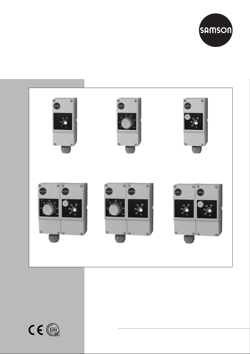
Thermostats
Safety Temperature Monitor (STM) Type 5343
Temperature Regulator (TR) Type 5344
Safety Temperature Limiter (STL) Type 5345
Double Thermostat TR/STL Type 5347
Double Thermostat TR/STM Type 5348
Double Thermostat STM/STL Type 5349
Type 5343 Safety Temperature
Monitor (STM)
Type 5347
Double Thermostat TR/STL
Type 5344
Temperature Regulator (TR)
Type 5348
Double Thermostat TR/STM
Type 5345 Safety Temperature
Double Thermostat STM/STL
Mounting and
Operating Instructions
EB 5206 EN
Edition January 2009
Limiter (STL)
Type 5349
Page 2

Contents
Contents Page
1 General safety instructions . . . . . . . . . . . . . . . . . . . . . . . 3
2 Design and principle of operation . . . . . . . . . . . . . . . . . . . 4
2.1 Typetesting. . . . . . . . . . . . . . . . . . . . . . . . . . . . . . . 4
2.2 Technical data . . . . . . . . . . . . . . . . . . . . . . . . . . . . . 5
2.3 Mounting accessories . . . . . . . . . . . . . . . . . . . . . . . . . . 7
3 Installation. . . . . . . . . . . . . . . . . . . . . . . . . . . . . . . 8
3.1 Mounting position . . . . . . . . . . . . . . . . . . . . . . . . . . . 8
3.2 Contact thermostat . . . . . . . . . . . . . . . . . . . . . . . . . . . 9
3.3 Thermowell. . . . . . . . . . . . . . . . . . . . . . . . . . . . . . . 9
3.3.1 Wall mounting with thermowell in a different location. . . . . . . . . . 10
3.3.2 Mounting on tanks or in pipes . . . . . . . . . . . . . . . . . . . . . 10
4 Electrical connection . . . . . . . . . . . . . . . . . . . . . . . . . 12
5 Operation . . . . . . . . . . . . . . . . . . . . . . . . . . . . . . 13
5.1 Temperature regulator (TR) . . . . . . . . . . . . . . . . . . . . . . 13
5.2 Safety temperature monitor (STM) . . . . . . . . . . . . . . . . . . . 13
5.3 Safety temperature limiter (STL) . . . . . . . . . . . . . . . . . . . . 13
6 Lead sealing . . . . . . . . . . . . . . . . . . . . . . . . . . . . . 14
7 Dimensions in mm . . . . . . . . . . . . . . . . . . . . . . . . . . 14
Definitions of the signal words used in these instructions
DANGER!
DANGER indicates a hazardous situation
which, if not avoided, will result in death or
NOTICE
NOTICE indicates a property damage
message.
serious injury.
Note: Supplementary explanations, infor
mation and tips
2 EB 5206 EN
-
Page 3

1 General safety instructions
General safety instructions
For your own safety, follow these instructions concerning the mounting, start-up and opera
tion of the thermostat:
The thermostat may only be mounted, started up or operated by trained and experienced
4
personnel familiar with the product.
According to these Mounting and Operating Instructions, trained personnel refers to
individuals who are able to judge the work they are assigned to and recognize possible
dangers due to their specialized training, their knowledge and experience as well as their
knowledge of the relevant standards.
On wiring and connecting the thermostat, you are required to observe the VDE
4
regulations and the regulations of the local power suppliers. Therefore, this type of work
must only be performed by trained personnel.
To avoid damage to any equipment, the following also applies:
Proper shipping and appropriate storage are assumed.
4
-
Note: The device with a CE marking fulfills the requirements of the Directives 2004/108/EC
and 2006/95/EC (EMC).
The Declaration of Conformity is available on request.
EB 5206 EN 3
Page 4
Design and principle of operation
2 Design and principle of
operation
Safety temperature monitors (STM)
The snap-action switch is triggered if the
temperature at the bulb rises above the ad
justed set point. When the temperature falls
below the set point by approximately 8 K,
the switch returns to its original position.
The electric circuit is opened when the tem
perature at the bulb falls below –20 °C. The
circuit is automatically closed again when
the temperature at the bulb rises above
–20 °C.
The circuit remains permanently open if the
measuring system is broken.
Temperature regulators (TR)
The snap-action switch is triggered if the
temperature at the bulb rises above the adjusted set point. When the temperature falls
below the set point by approximately 4 K,
the switch returns to its original position.
-
-
The circuit remains permanently open if the
measuring system is broken. It is not possi
ble to unlock the device.
-
2.1 Typetesting
The thermostats are typetested by the Ger
man Technical Inspectorate (TÜV) according
to DIN EN 14597.
Type DIN register number
5343 STW120908
5344 TR120808
5345 STB120708
-
Safety temperature limiters (STL)
The snap-action switch is triggered and
locked if the temperature at the bulb rises
above the adjusted set point. When the tem
perature falls below the set point by approx
imately 10 %, the snap-action switch can be
unlocked manually.
The electric circuit is opened when the tem
perature at the bulb falls below –20 °C. The
circuit is automatically closed again when
the temperature at the bulb rises above
–20 °C.
4 EB 5206 EN
-
-
-
Page 5
Design and principle of operation
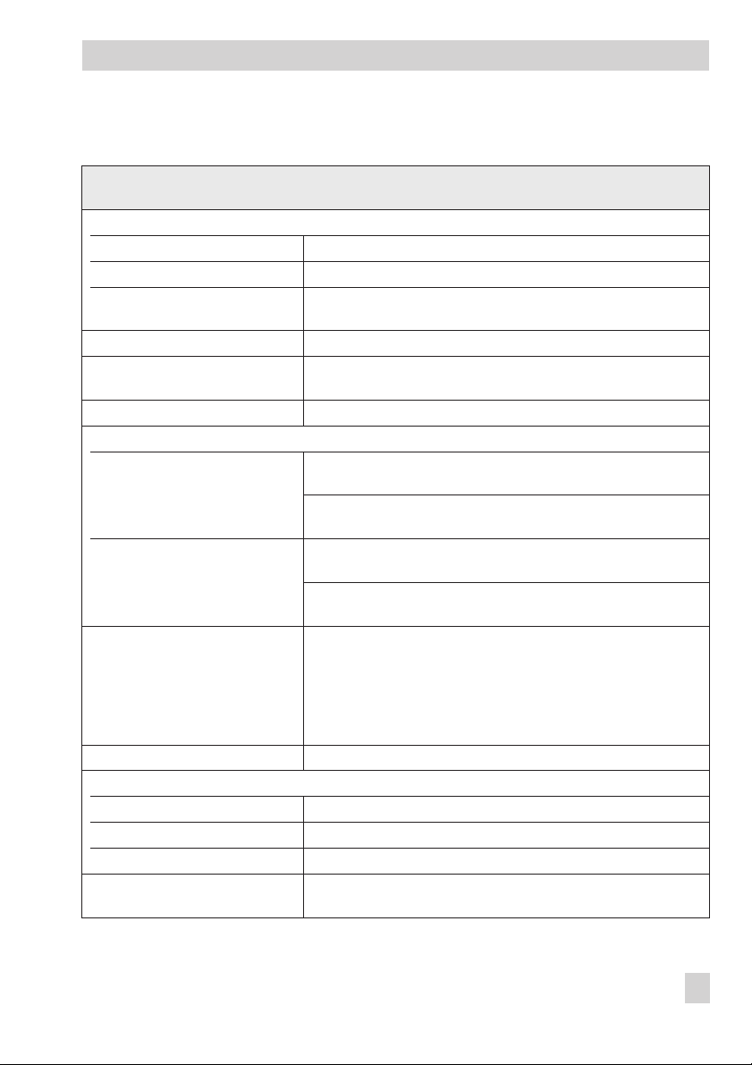
2.2 Technical data
Single thermostats: Type 5343 (STM), Type 5344 (TR), Type 5345 (STL)
Double thermostats: Type 5347 (TR/STL), Type 5348 (TR/STM), Type 5349 (STM/STL)
Permissible ambient temperature
Transportation and storage –30 to +50 °C
Service Max. +80 °C
Max. pipe temperature when
mounted as a contact thermostat
Degree of protection IP 54 according to EN 60529
Cable entry M20 x 1.5 cable gland,
Minimum switching capacity AC/DC = 24 V, 100 mA
Maximum switching capacity
Temperature regulator (TR),
Safety temperature monitor (STM)
Safety temperature limiter (STL)
Influence of mean ambient
temperature based on the set point
Connection Spring-clamp terminals, 0.75 to 2.5 mm² wire cross-section
Materials
Bottom section of the housing PA (reinforced)
Housing cover ABS with window (PMMA)
Bulb and capillary Cu (copper)
Weight Single thermostat approx. 0.225 kg
Max. +120 °C
suitable for 6 to 12 mm cable diameter
With 230 V AC
+10 %
With 230 V DC
+10 %
With 230 V AC
+10 %
With 230 V DC
+10 %
A shift of the switching point arises when the ambient temperature
at the knob and at the capillary deviates from the calibration am
bient temperature of +22 °C:
Higher ambient temperature→Lower switching point
Lower ambient temperature→Higher switching point
This influence is minimized by temperature compensation.
Double thermostat approx. 0.45 kg
NC contact:
NO contact:
NC contact:
NO contact:
NC contact:
Signal contact:
NC contact:
Signal contact:
16 A (2.5); cosϕ= 1 (0.6)
6.3 A (2.5); cosϕ= 1 (0.6)
0.25 A
0.25 A
16 A (2.5); cosϕ= 1 (0.6)
2 A (2.5); cosϕ= 1 (0.4)
0.25 A
0.25 A
-
EB 5206 EN 5
Page 6
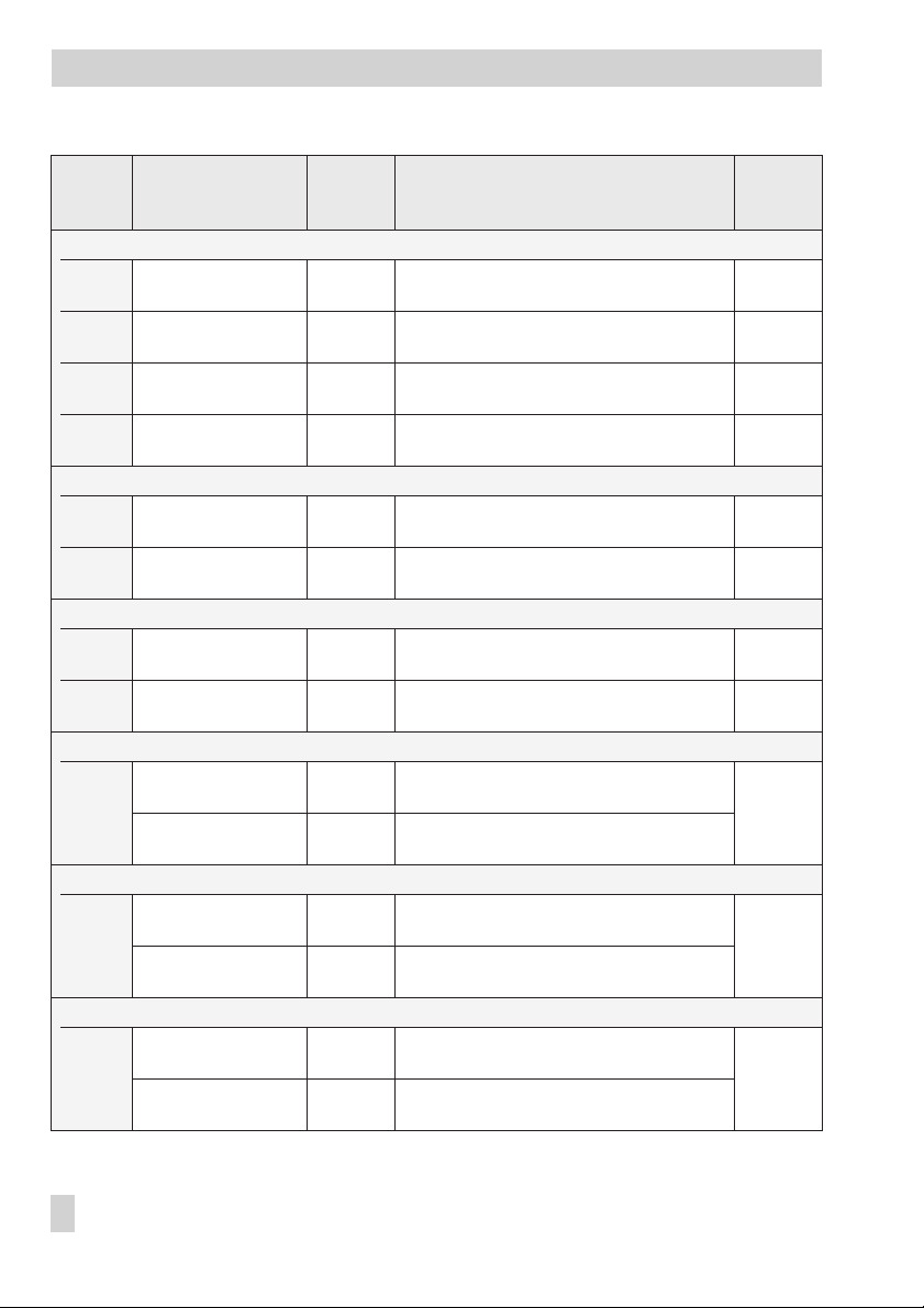
Design and principle of operation
Switching
differential
Type Set point range
Safety temperature monitor (STM)
5343-1 0 to +60 °C
5343-2 +40 to +100 °C
5343-3 +70 to +130 °C
5343-4 +35 to +95 °C
Temperature regulator (TR)
5344-1 0 to +120 °C
5344-2 +20 to +150 °C 4 K
Safety temperature limiter (STL)
5345-1 +70 to +130 °C 10 K
5345-2 +30 to +90 °C
Double thermostat TR/STL
TR: 0 to +120 °C
5347-1
STL: +70 to +130 °C
Double thermostat TR/STM
TR: 0 to +120 °C
5348-1
STM: +70 to +130 °C
Double thermostat STM/STL
STM: +70 to +130 °C
5349-1
STL: +70 to +130 °C
approx. Switching point accuracy
8 K
8 K
8 K
8 K
3 K
10 K
3 K
8 K
3 K
8 K
8 K
8 K
Range
Range
Range
Range
Range
Range
Range
Range
Range
Range
Range
Range
Range
Range
Range
Range
Range
Range
Range
Range
Range
Range
Range
Range
Range
Range
Range
Range
0 to +30 °C:
+30 to +60 °C:
+40 to +70 °C:
+70 to +100 °C:
+70 to +100 °C:
+100 to +130 °C:
+35 to +65 °C:
+65 to +95 °C:
0 to +60 °C:
+60 to +120 °C:
+20 to +85 °C:
+85 to +150 °C:
+70 to +100 °C:
+100 to +130 °C:
+30 to +60 °C:
+60 to +90 °C:
0 to +60 °C:
+60 to +120 °C:
+70 to +100 °C:
+100 to +130 °C:
0 to + 60 °C:
+60 to +120 °C:
+70 to +100 °C:
+100 to +130 °C:
+70 to +100 °C:
+100 to +130 °C:
+70 to +100 °C:
+100 to +130 °C:
+0 K
+0 K
+0 K
+0 K
+0 K
+0 K
+0 K
+0 K
+6 K
+3 K
+6 K
+3 K
+0 K
+0 K
+0 K
+0 K
+6 K
+3 K
+0 K
+0 K
+6 K
+3 K
+0 K
+0 K
+0 K
+0 K
+0 K
+0 K
–12 K
–5 K
–5 K
–12 K
–5 K
–12 K
–5 K
–12 K
–6 K
–3 K
–6 K
–3 K
–5 K
–12 K
–5 K
–12 K
–6 K
–3 K
–5 K
–12 K
–6 K
–3 K
–5 K
–12 K
–5 K
–12 K
–5 K
–12 K
Max.
medium
temp.
+85 °C
+125 °C
+155 °C
+120 °C
+145 °C
+175 °C
+155 °C
+115 °C
+145 °C
+145 °C
+145 °C
6 EB 5206 EN
Page 7

Design and principle of operation
2.3 Mounting accessories
Thermowells
The thermostat is supplied without a thermowell. The following thermowells are available for
single and double thermostats as accessories:
Thermowells for single thermostat Max. pressure at 150 °C
Nickel-plated brass · CuZn (2.0401)
100 x 8 mm
150 x 8 mm
200 x 8 mm
CrNiMo steel (1.4571)
100 x 8 mm
150 x 8 mm
300 x 8 mm
Thermowells for double thermostat Max. pressure at 150 °C
Nickel-plated brass · CuZn (2.0401)
100 x (2x 8 mm)
150 x (2x 8 mm)
CrNiMo steel (1.4571)
150 x 15 mm
300 x 15 mm
48 bar 1400-9844
48 bar 1400-9845
48 bar 1400-9846
88 bar 1400-9848
88 bar 1400-9849
88 bar 1400-9850
48 bar 1400-9901
48 bar 1400-9851
48 bar 1400-9853
48 bar 1400-9854
Note: The scope of delivery of the thermowell includes:
–
A clip to fasten the capillary to the thermowell (see section 3.3.1)
–
A small metal plate with screw to attach the thermostat to the thermowell (see sec
tion 3.3.2)
Order no.
Order no.
-
Strap
Strap for mounting the contact thermostat
(15 to 100 mm pipe diameter)
1400-9865
EB 5206 EN 7
Page 8
Installation
3 Installation
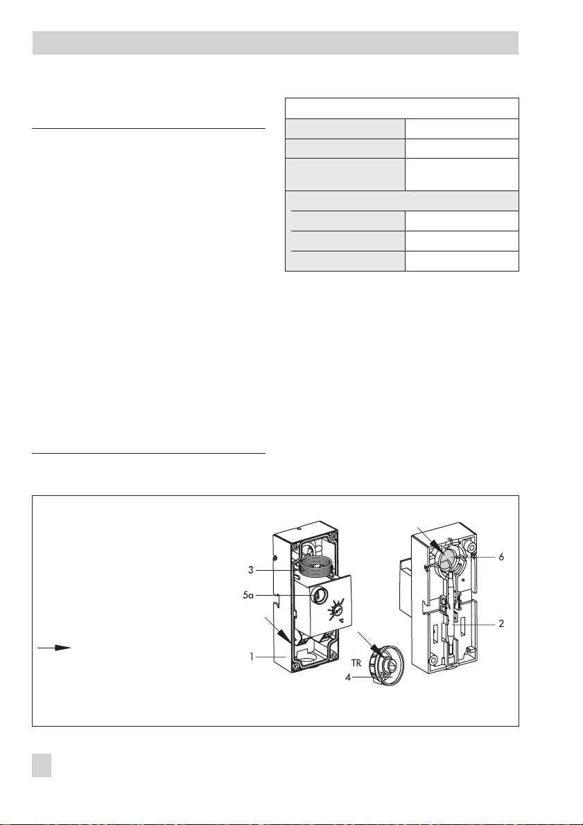
NOTICE!
On installing the thermostat, follow the in
structions described below to prevent dam
age to the thermostat and to ensure it can
function properly:
The degree of protection IP 54 cannot be
–
met when the seals are missing or when
they are incorrectly inserted into the ther
mostat (Fig. 1)!
Do not remove the seals in the housing
(1) and on the set point adjuster of the
temperature regulator (4).
The thermostat must only be operated
with inserted seal (6).
A damaged capillary will cause the mea-
–
suring fluid to leak out (see Table 1) leading to the permanent failure of thermostat!
Do not bend or cut the capillary. The
smallest bending radius must not be
smaller than 5 mm.
Table 1 · Properties of the measuring fluid
Dangerous reaction No
Ignition temperature +375 °C
-
Water pollution Class 1
-
Toxicological specifications
Irritant No
Risk to health No
-
Toxic No
Slightly contaminating
3.1 Mounting position
Contact thermostat
The thermostat must not be suspended with
the bottom of the housing (containing the
bulb) facing upwards.
Thermostat with thermowell
Any mounting position can be chosen.
1 Thermostat
2 Bulb
3 Capillary
4 Set point adjuster (TR only)
5a Spring for unlocking (STL only)
6 Seal
Seals necessary to achieve degree
of protection IP 54
Fig. 1 · Seals necessary to achieve degree of protection IP 54
8 EB 5206 EN
Page 9

Installation
3.2 Contact thermostat
You can attach single thermostats to pipes
with diameters between 15 and 100 mm. A
strap is required in this case (see section 2.3
on accessories).
1. Insert seal (6) as shown in Fig. 2.
2. Thread the strap (8) behind the bulb
holder at the back of the housing (1).
3. Use the strap to attach the thermostat to
the pipe.
4. Unscrew the front cover of the thermo
stat.
5. Perform electrical connection as described in section 4.
6. Screw front cover back onto the thermostat.
TR: Place the set point adjuster onto the
temperature regulator.
1 Thermostat
2 Bulb
6 Seal
8 Strap
Fig. 2 · Mounting a contact thermostat
-
3.3 Thermowell
Note: The bulbs of double thermostats share
the same thermowell. See section 2.3.
Before attaching the thermostat, uncoil the
length of capillary required:
For wall mounting, the required length
4
depends on the required capillary and
length of the thermowell
For mounting the thermostat on tanks/in
4
pipes, the required length depends on
the length of the thermowell
NOTICE
Do not pull at the bulb on uncoiling the capillary! The capillary tube may break.
1. Unscrew front cover from the thermostat.
2. Detach the bulb from the back of the
thermostat.
3. Route the bulb through the back of the
housing to the front.
4. Uncoil the capillary to the required
length (Fig. 4a).
5. Route the bulb back again through the
back of the housing (Fig. 4a).
6. Insert seal (6) as shown in Fig. 4b or
4c.
Proceed as described in section 3.3.1 or in
section 3.3.2 depending on how the ther
mostat is to be mounted.
-
EB 5206 EN 9
Page 10

Installation
3.3.1 Wall mounting with thermo
-
well in a different location
The thermostats are fastened to the wall
using two screws (not included in the scope
of delivery).
7. Drill holes in wall as shown in Fig. 3.
8. Insert seal (6).
9. Fix the capillary in the notch at the side
of the thermostat housing or let it run
down the middle (Fig. 4b).
10. Fasten the back of the housing (1) using
two screws to the wall.
11. Screw the thermowell (7) into the pipe
or tank.
12. Push the bulb (2) as far as it will go into
the thermowell (7).
13. Fasten the capillary (3) to the
thermowell (7) using the supplied clip
(7a).
14. Perform electrical connection as described in section 4.
15. Screw front cover onto the thermostat.
TR: Place set point adjuster onto the temper
ature regulator.
3.3.2 Mounting on tanks or in
pipes
The thermostats are attached to the
thermowells which are screwed into place.
7. Insert seal (6).
8. Screw thermowell (7) into the pipe or
tank.
9. Insert small metal plate (7b) at the back
of the housing (1) and secure in place
with the screw (7c).
10. Push the bulb (2) as far as it will go into
the thermowell (7), making sure that the
round hole at the back of the housing
(1) rests on the collar on the thermowell.
11. Push the thermostat slightly lengthways
to allow the thermowell to engage.
12. Tighten screw (7c) until the housing is
fixed into place on the thermowell.
13. Perform electrical connection as de-
scribed in section 4.
14. Screw front cover onto the thermostat.
TR: Place set point adjuster onto the temper
-
ature regulator.
-
Single
thermostat
Fig. 3 · Drill patterns
10 EB 5206 EN
42.4
Double
thermostat
95
Ø 4.5
95
95.4
Ø 4.5
Page 11

Fig. 4a · Uncoiling the capillary
Installation
Fig. 4b · Wall mounting with the thermowell in a
different location
7a 3
7
1
2
6
Fig. 4 · Mounting the thermowell
Fig. 4c · Mounting on tanks or in pipes
1 Thermostat
2 Bulb
3 Capillary
6 Seal
7 Thermowell
7a Clip
7b Small metal plate
7c Screw
EB 5206 EN 11
Page 12

Electrical connection
4 Electrical connection
DANGER!
Risk of electric shock!
For electrical installations, you are re
–
quired to observe the regulations con
cerning electrical power installations ac
cording to DIN VDE 0100 as well as the
regulations of your local power supplier.
Use a suitable power supply to ensure
–
that no dangerous voltages from the sys
tem or parts of the system reach the
thermostat in standard operation or in
case of a fault.
Connect the thermostat at the PE terminal
–
to the ground wire. This wire must have
at least the same cross section as the
supply cable.
The wires of double thermostats are
–
routed through the opening in the intermediate wall to the second thermostat.
Seal the opening not used for cable entry
with a blanking cap.
Cable entry
Route the wires through the cable gland
(M20 x 1.5) into the inside of the thermo
stat.
The spring-clamp terminals are designed for
a wire cross-section of 0.75 to 2.5 mm².
Wiring the thermostat
Open the thermostat housing and wire the
thermostat according to Fig. 5:
Rigid wire ends: Strip 11 to 13 mm insu
4
lation off the cable and place it into the
terminal point ( ) as far it will go.
Flexible wire ends without ferrules: Use
4
a slotted screwdriver to keep the spring
open (in ) and place the wire ends
into the terminal point ( ) as far they
-
-
-
will go.
Flexible wire ends with ferrules: Fit
4
ferrule to wire ends. Refer to
EN 60947-1. Use a suitable crimping
tool!
Place the wire ends into the terminal
-
point ( ) as far they will go.
Note: The wire ends can be pulled out by
holding the spring open with a slotted
screwdriver (in ).
NC contact 1 – 2
NO contact 1 – 4
-
1
Temperature
Regulator (TR),
Safety Temperature
Monitor (STM)
-
Safety Temperature
Limiter (STL)
Fig. 5 · Electrical wiring
42
1
42
12 EB 5206 EN
Page 13

Operation
5 Operation
5.1 Temperature regulator (TR)
Adjust the set point at the set point adjuster
(4).
Limiting the set point range
The lower range value and upper range
value of the set point range can be limited.
4a
4
4 Set point adjuster
4a Pin to limit the set point range
5.2 Safety temperature
monitor (STM)
Open the thermostat housing and adjust the
set point using a screwdriver.
5.3 Safety temperature
limiter (STL)
Open the thermostat housing and adjust the
set point using a screwdriver.
Resetting the safety temperature limiter
Note: The safety temperature limiter can
only be reset after the temperature has fallen
below the adjusted limit by approximately
10 %.
Use a screwdriver to unlock the thermostat.
5a
1. Turn the set point adjuster (4) to a value
within the required temperature range.
2. Pull the set point adjuster (4) off the
temperature regulator.
3. Break off the pin (4a).
4. Insert the pin (4a) at the point where the
temperature is to be limited (min./max.
temperature).
5. Place the set point adjuster back on the
temperature regulator.
5
5 Screw lid
5a Spring for unlocking
1. Open screw lid (5).
2. Use a screwdriver to move the spring
(5a) from the bottom to the top as far as
it will go.
EB 5206 EN 13
Page 14

Lead sealing
6 Lead sealing
NOTICE
Only lead-seal in the gray-colored area,
otherwise the thermostat cannot function
properly.
Note: You have to drill the holes for the lead
sealing. The lead seal is not included in the
scope of delivery.
7 Dimensions in mm
Single thermostats
Type 5343 Safety Temperature Monitor (STM)
53 42.4
22
**
30
15
8
16
Dimensions with thermowell (accessories)
58
˚C
14 EB 5206 EN
120
150
Ø 4.5
95
300
200
150
15
G1/2
100
Ø8
Page 15

Dimensions in mm
Type 5344 Temperature Regulator (TR)
53 42.4
22
120
˚C
150
Type 5345 Safety Temperature Limiter (STL)
53 42.4
22
120
150
**
Ø 4.5
95
**
Ø 4.5
95
Dimensions with thermowell (accessories)
70
15
300
200
150
100
G1/2
Ø8
Dimensions with thermowell (accessories)
63
58
15
300
200
150
100
G1/2
Metal plate and screw for fastening the thermostat onto the thermowell (wall mounting)
**
Ø8
EB 5206 EN 15
Page 16

Dimensions in mm
Double thermostats
Type 5347 Double Thermostat TR/STL
Type 5348 Double Thermostat TR/STM
Dimensions with thermowell (accessories)
70
100
150
300
G1/2
Ø15
Dimensions with thermowell (accessories)
70
100
150
300
G1/2
16 EB 5206 EN
Ø15
Page 17

Dimensions in mm
Type 5349 Double Thermostat STM/STL
Metal plate and screw for fastening the thermostat onto the thermowell (wall mounting)
**
Dimensions with thermowell (accessories)
63
58
100
150
300
G1/2
Ø15
EB 5206 EN 17
Page 18

18 EB 5206 EN
Page 19

EB 5206 EN 19
Page 20

SAMSON AG · MESS- UND REGELTECHNIK
Weismüllerstraße 3 · 60314 Frankfurt am Main · Germany
Phone: +49 69 4009-0 · Fax: +49 69 4009-1507
Internet: http://www.samson.de
EB 5206 EN
2009-01
 Loading...