

Page 1

Headset Wireless Systems
Qe Fitness Headset
DE10x Headset
OWNER'S MANUAL
Page 2

Important Safety Information
1. Read these instructions.
2. Keep these instructions.
3. Heed all warnings.
4. Follow all instructions.
5. Do not use this apparatus near water.
6. Clean only with dry cloth.
7. Do not block any ventilation openings. Install in accordance with the manufacturer’s
instructions.
8. Do not install near any heat sources such as radiators, heat registers, stoves, or other
apparatus (including amplifiers) that produce heat.
9. Do not defeat the safety purpose of the polarized or grounding type plug. A polarized plug
has two blades with one wider than the other. A grounding type plug has two blades and
a third grounding prong. The wide blade or the third prong are provided for your safety. If
the provided plug does not fit into your outlet, consult an electrician for replacement of the
obsolete outlet.
10. Protect the power cord from being walked on or pinched particularly at the plugs,
convenience receptacles, and at the point where they exit from the apparatus.
11. Only use attachments/accessories specified by the manufacturer.
12. Use only with the cart, stand, tripod, bracket, or table specified by the
manufacturer, or sold with the apparatus. When a cart is used, use caution
when moving the cart/apparatus combination to avoid injury from tip-over.
13. Unplug the apparatus during lightening storms, or when unused for long periods of time.
14. Refer all servicing to qualified personnel. Service is required when the apparatus has
been damaged in any way, such as power supply cord or plug is damaged, liquid has been
spilled or objects have fallen into the apparatus has been exposed to rain or moisture, does
not operate normally, or has been dropped.
15. This appliance shall not be exposed to dripping or splashing water and that no object filled
with liquid such as vases shall be placed on the apparatus.
16. Caution-to prevent electrical shock, match wide blade plug wide slot fully insert.
17. Please keep a good ventilation environment around the entire unit.
18. The direct plug-in adapter is used as disconnect device, the disconnect device shall
remain readily operable.
19. Batteries (battery pack or batteries installed) shall not be exposed to excessive heat such
as sunshine, fire or the like.
If you want to dispose this product, do not mix it with general household waste. There is
a separate collection system for used electronic products in accordance with legislation
that requires proper treatment, recovery and recycling.
Private household in the 28 member states of the EU, in Switzerland and Norway may
return their used electronic products free of charge to designated collection facilities or to a
retailer (if you purchase a similar new one).
For Countries not mentioned above, please contact your local authorities for a correct method of
disposal.
By doing so you will ensure that your disposed product undergoes the necessary treatment, recovery and recycling and thus prevent potential negative effects on the environment and human
health.
Copyright 2019, Samson Technologies Corp V1.5
Samson Technologies Corp.
278-B Duffy Ave
Hicksville, NY 11801
www.samsontech.com
2
Page 3

Important Safety Information
FCC Rules and Regulations
Samson wireless receivers are certified under FCC Rules part 15 and transmitters are certified
under FCC Rules part 74. Licensing of Samson equipment is the user’s responsibility and
licensability depends on the user’s classification, application and frequency selected.
This device complies with Part 15 of the FCC rules Class B and RSS-210 of Industry & Science
Canada.
Operation is subject to the following two conditions:
(1) This device must not cause harmful interference, and
(2) This device must accept any interference received including interference that
may cause undesired operation. Suitable for home or office use.
NOTE: This equipment has been tested and found to comply with the limits for a Class B digital
device, pursuant to Part 15 of the FCC Rules. These limits are designed to provide reasonable
protection against harmful interference in a residential installation. This equipment generates,
uses and can radiate radio frequency energy and, if not installed and used in accordance with
the instructions, may cause harmful interference to radio communications. However, there is
no guarantee that interference will not occur in a particular installation. If this equipment does
cause harmful interference to radio or television reception, which can be determined by turning
the equipment off and on, the user is encouraged to try to correct the interference by one or
more of the following measures:
• Reorient or relocate the receiving antenna.
• Increase the separation between the equipment and receiver.
• Connect the equipment into an outlet on a circuit different from that to which the
receiver is connected.
• Consult the dealer or an experienced Radio/T V technician for help.
WARNING: Changes or modifications not expressly approved by the party responsible for
compliance could void the user’s authority to operate the equipment.
This equipment is intended for use in wireless microphone applications.
Equipment is intended for sale in: AT, BE, CH, CY, CZ*, DK, EE, FI*, FR*, DE*, GR*, HU, IE, IS,
IT, LV, LT*, LU, MT*, NL, NO*, PL* PT, RO, SK, SI, ES, SE, UK
*Subject to license. Please contact your national frequency authority for information on
available legal use in your area. Any changes or modifications not expressly approved by
Samson Technologies Corp. could void your authority to operate the equipment.
Hereby, Samson Technologies Corp., declares that this AR99m and AH9 is in compliance
with the essential requirements and other relevant provisions of Directive 2014/53/EU. The
declaration of conformity may be consulted at:
http://www.samsontech.com/site_media/support/manuals/AirLine99m_ AH9_DOC.pdf
AirLine 99m Wireless System 3
Page 4

Introduction
Welcome to Samson AirLine, the original micro-wireless microphone systems. Wireless
microphone and instrument systems were originally developed to eliminate cables, providing
unparalleled freedom of movement. AirLine 99m takes this concept to a new level with
frequency agile transmitters and micro receiver, providing a completely “hassle-free” user
experience.
Featuring miniaturized circuitry and an internal, rechargeable battery the AH9 can operate
for up to 8 hours on a single charge. The AirLine 99m System combines an AH9 headset
transmitter with a Samson Qe Fitness or DE10 low profile headset microphone.
Offering frequency-agile UHF operation, the micro-sized True RF Diversity AR99m receiver
provides 100 available channels to secure reliable wireless performance. The receiver provides
easy setup with 1-touch scan which analyzes and selects the clearest operating channel,
infrared set to pair the transmitter with the receiver, and versatile output connections (XLR,
1/4” and 1/8”). An included USB port can be used to charge the AH9 transmitter or integrate a
Samson XPD Series wireless system (sold separately) to make it a dual-receiver.
In these pages, you’ll find a detailed description of the features of the AirLine 99m System, as
well as step-by-step instructions for its setup and use. If your wireless system was purchased
in the United States, you’ll also find a registration card enclosed—don’t forget to follow the
instructions so that you can receive online technical support and so that we can send you
updated information about this and other Samson products in the future. Also, be sure to
check out our website www.samsontech.com for complete information about our full product
line.
We recommend you keep the following records for reference, as well as a copy of your sales
receipt:
Receiver Serial number: _________________________________________
Transmitter Serial number: ______________________________________
Date of purchase: ______________________________________________
If you have any questions or comments regarding the AirLine 99m Microphone System or any
other products from Samson, do no hesitate to contact us at support@samsontech.com.
With proper care and maintenance, your AirLine 99m System will operate trouble-free for many years.
Should your AirLine 99m System ever require servicing, a Return Authorization (RA) number must
be obtained before shipping your unit to Samson. Without this number, the unit will not be accepted.
Please visit www.samsontech.com/ra for an RA number prior to shipping your unit. Please retain the
original packing materials and, if possible, return the unit in its original carton. If your AirLine 99m
System was purchased outside of the United States, contact your local distributor for warranty details
and service information.
4
Page 5

AR99m Receiver Features
1. Antennas - The antenna mountings allow
full rotation for optimum placement. In
normal operation, both antennas should
be placed in a vertical position. Both
antennas can be folded inward for
convenience when transporting the
AR99m.
2. SET Button - Press this button to scan
through the receiver’s 100 operating
channels to find the optimal channel for
performance. Once the scan is complete,
the AR99m will enter IR Set mode
and send the selected channel to the
tr ansmitte r.
3. LED Display - The two digit, 7-segment
LED display shows the receiver’s current
operating channel.
4. READY Indicator - This indicator lights
green when the CR99m is receiving RF
signal and the system is ready to use.
5. IR Transmitter - During “IR SET” an infrared light is used to set the transmitter channel.
6. PEAK Indicator - This indicator lights red when the transmitted audio signal is overloaded.
7. VOLUME / Power Control - This rotary knob controls the level of the receiver output and
powers the AR99m on and off. Turn the control clockwise to turn the system on. Turn the
knob counterclockwise until it clicks to turn the system off.
8. USB Port - This USB port provides 5V
200mA of power which can be used to
charge the AH9 headset transmitter or a
small portable USB device like an MP3
player or smartphone (AR99m only pass
power to the USB port when the power
is ON). It can also be used to connect
an optional Samson XPD USB Digital
Wireless receiver to this input, turning
the AR99m into a dual wireless system.
1 1
7
5
4 6
32
8
AirLine 99m Wireless System 5
Page 6

AR99m Receiver Features Rear Panel
1 2 2 3
1. DC Input - Connect the supplied power adapter here.
WARNING: Do not substitute any other kind of power adapter. Doing so can cause severe
damage to the AR99m and will void your warranty.
2. UNBALANCED OUTPUTS - Use these unbalanced 1/4” and 1/8” jacks when connecting
the AR99m to consumer (-10 dBV) audio equipment. Wiring is as follows: tip hot, sleeve
ground.
3. BALANCED OUTPUT - Use this electronically balanced low impedance (600 Ohm) XLR jack
when connecting the AR99m to professional (+4 dBu) audio equipment. Pin wiring is as
follows: Pin 1 ground, Pin 2 high (hot), and Pin 3 low (cold).
6
Page 7

AH9 Headset Transmitter Callouts
1
34
2
5
1. Power/Mute Button - Press and hold for 3 seconds to turn the unit on or off. A quick press
and release will mute or un-mute the transmitter when the transmitter is on.
2. Status Indicator - This LED displays the operation mode, low battery and recharge status of
the transmitter. The chart below defines the LED colors for each function.
GREEN Normal Operation
AMBER Mute
Flashing RED
RED Fully Charged
Low Battery
Charging
3. Volume +/– Buttons - Press and hold either Volume button to adjust the volume. Pressing
the + or – button increases or decrease the level by one step with each push of the
button. There is a total 9 volume levels. The Status Indicator light will flash faster for each
increased step and slower for each decrease.
4. IR Lens - This window is used to capture the infrared signal sent from the receiver during
the IR SET to channelize the transmitter. The IR Lens is only active for the first 10 seconds
when the transmitter is powered on.
5. Charging Connector - Connect the supplied magnetic charging cable to this sealed, gold
contact charging connector to recharge the internal Lithium Ion battery. The AH9 can be
recharged by connecting the cable to the USB connector on the AR99m reciever or any
5-volt DC adapter that has a USB output.
AirLine 99m Wireless System 7
Page 8

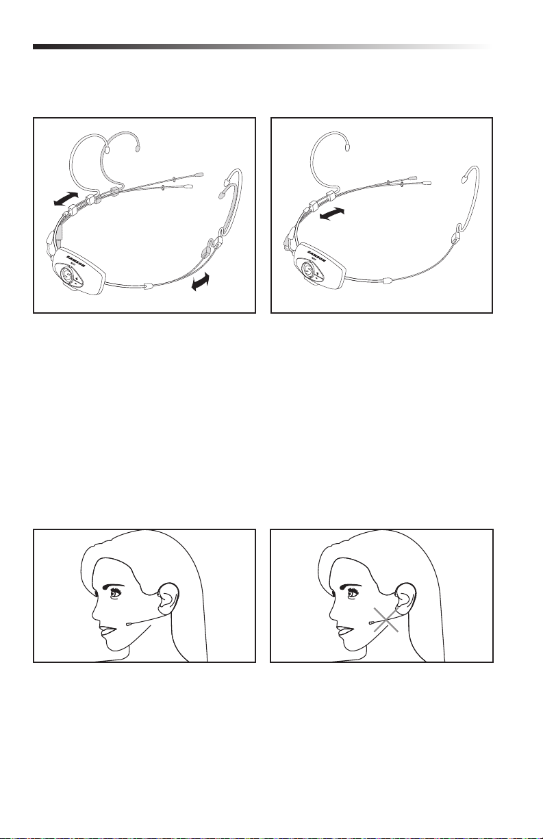
Wearing the AH9 Headset Microphone
As shown in the illustration, the correct way to wear your Qe fitness headset microphone, is
over the ears, as you would wear a pair of eyeglasses. Because the Qe microphone is specially
designed to be used up close, be sure to position the microphone directly in front of your lips.
To avoid feedback problems, take care not to cover the microphone capsule with your hand.
Position the headset over your head so
that the body of the transmitter is behind
your head. Adjust the headset so that it fits
comfortably on your ears and is secure against
your head.
Note: If wearing glasses, it is recommended
to put the AH9 transmitter on first than place
glasses over the transmitter.
For added comfort and fit, the headset
includes an adjustable headband. To fit the
headband, pull elastic strap over the ear
hooks and locate in front of the stop point
(A). For larger sizing, the headband can be
moved behind the stop point (B) or completely
removed by sliding the elastic band over the
ear hooks and microphone capsule.
Note: When removing the headband, first take
off the microphone windscreen.
8
Page 9
DE10 Headse t
Fitting the DE10 Headset
The DE10 headset can be sized by sliding the
ear hooks to fit snug around your head. If the
DE10 is loose and will not stay in place, slide
the ear hook wires back for a tighter fit.
Mic Positioning
Position the DE10 microphone element about
0.25” –1” behind the corner of your mouth.
Since the DE10 is an omnidirectional capsule,
the end of the microphone does not need to
be facing your mouth. To avoid breadth noise
and p-pops, do not place the microphone
directly in front of your mouth.
Adjust the microphone position by holding
the left ear hook wire and slide the boom
forward or back. For optimum performance
the microphone should be close to the
skin and towards the corner of the mouth,
approximately a half inch away.
Position the moisture guard ring as close to
the capsule as possible.
For outdoor use and to help reduce
p-popping, use the included windscreens.
If the microphone is too far away from your
mouth you will need to increase the gain and
reduce isolation.
To minimize additional noise, do not locate
the microphone tight against your cheek.
AirLine 99m Wireless System 9
Page 10

Quick Start
In order for your wireless system to work correctly, both the receiver and transmitter must be set
to the same channel. Follow this basic procedure for setting up your AirLine 99 wireless system:
1. Physically place the AR99m receiver where it will be used, and extend the antennas
vertically. The general rule of thumb is to maintain “line of sight” between the receiver and
transmitter so that the person using or wearing the transmitter can see the receiver.
2. Ensure that the AH9 transmitter is fully charged (see section Charging the AH9 Transmitter).
3. With the AR99m powered off, connect the included power adapter.
4. With your amplifier or mixer off and volume control all the way down, connect the AR99m
receiver output jack to the mic or line level input of a mixer or amplifier using the balanced
XLR output or unbalanced 1/4” or 1/8” line level outputs. Turn the VOLUME knob on the
AR99m clockwise to turn its power on, but keep the level low.
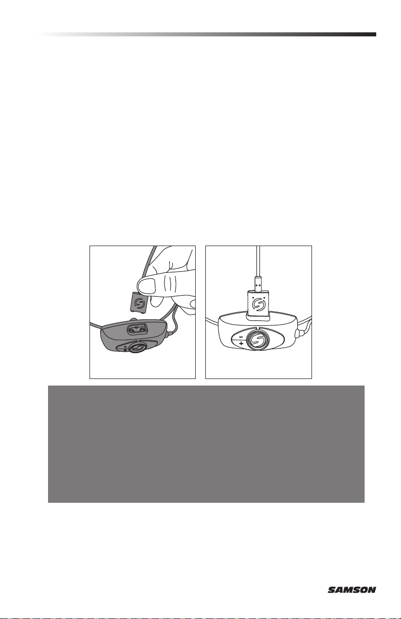
5. Press and hold the SET button on the front of the AR99m receiver to scan for an available
channel. Once the optimal channel is
selected the receiver will enter IR Set
mode (figure 1).
6. Turn on the power to the AH9 transmitter
by pressing and holding the Power button
for 3 seconds; the indicator LED will light
yellow when the button is pressed and
turns green when released and the AH9
is powered on.
7. Position the AH9 transmitter about
6-12” (15-30 cm) from the front of the
AR99m with the transmitter’s IR window
facing the IR transmitter on the front
panel of the AR99m receiver (figure 2).
8. When the transmission of the operating
channel is complete, the AR99m will
receive RF signal and the READY
indicator will light indicating that it
is receiving wireless signal from the
tr ansmitte r.
Note: The AH9 will only accept infrared
transmission from the receiver for
the first 10 seconds after the AH9 is
powered on. If you need to change the
operating channel, the AH9 must be first
powered off, then powered on again to
receive the new channel.
9. Turn on your connected amplifier or
mixer, but keep the volume all the way
down. Set the Volume knob on the
AR99m fully clockwise. This is unity
gain. Speak or sing into the microphone at normal performance level. Slowly raise the
volume of your amplifier or mixer until the desired level is reached.
10. When using multiple systems, each system must be set to a different operating channel.
Follow these steps to set each receiver and transmitter to the optimal channel.
10
Figure 1
Figure 2
Page 11

Connecting XPD Wireless
1. Plug the XPD USB receiver into the USB
jack on the side of the AR99m receiver.
2. Place a fresh set of AA (LR6) batteries
in the transmitter battery holder, taking
care to observe the polarity markings.
3. Turn the AR99m receiver on by rotating
the VOLUME control clockwise. The
AR99m VOLUME control will affect the
mix of the AH9 and XPD transmitters.
4. Turn on the power to the XPD transmitter
by pressing and holding Power switch;
the indicator LED will light amber.
5. If the transmitter and receiver have not
been previously paired, press and hold
the button on the XPD receiver for >5
seconds, until it begins to flash. Press
and continue to hold the Power button on
the transmitter until the LED indicators
on both units light steady, indicating that
the receiver and transmitter are paired
and ready for operation.
6. Speak or sing into the microphone at
a normal performance level and raise
the AR99m VOLUME control until the
desired level is reached.
7. To balance the level between the AH9
and XPD transmitter, use the supplied
screwdriver to adjust the Gain control
inside the XPD battery compartment.
If you hear distortion from the XPD
transmitter turn down the Gain.
Conversely, if you hear a weak, noisy
signal at the desired volume level, turn
the Gain control in the XPD transmitter
slowly clockwise until the signal reaches
an acceptable level.
AirLine 99m Wireless System 11
Page 12
Charging the AH9 Transmitter
1. With the AR99m powered off, connect the included power adapter.
2. Insert the magnetic power cable to the AR99m USB Port (or any 5-volt DC adapter that
has a USB port).
3. Turn the VOLUME knob on the AR99m clockwise to turn its power on.
4. Place the AH9 transmitter on a flat surface.
5. Attach the magnetic connector to the gold contact power port on the bottom of the AH9
transmitter. The cable attaches to the port magnetically.
The magnetic connector is keyed so it will only connect in one direction.
Note: Transmission is disabled during charging.
6. Look at the indicator light on the AH9 transmitter to determine when the transmitter has
finished charging. When the light is flashing red, the AH9 is charging. When the red light
stops flashing it indicates that the AH9 is fully charged.
7. Disconnect the magnetic power cable from the AH9 when the unit is fully charged.
If you notice your AH9 battery life is becoming shorter after a full charge, you can order a user
replaceable battery from your local Samson distributer.
Getting the most out of the rechargeable battery:
• Completely charge the batteries before first use
• Fully charge the battery before it will be used.
• After the battery is charged, unplug the charger from the outlet.
• The optimal temperature range for using and storing the battery is 50°F 86°F (30°C - 50°C). The battery performance and operation may decrease in
temperatures below 50°F (30°C).
A warning that batteries (battery pack or batteries installed) shall not be exposed to excessive
heat such as sunshine, fire or the like.
CAUTION: Danger of explosion if battery is incorrectly replaced. Replace only with the same or
equivalent type. Attention should be drawn to the environmental aspects of battery disposal
12
Page 13

Specifications
System
Working Range 300' (100m) line of sight
Audio Frequency Response 50 Hz - 15 kHz
T.H.D. (Overall) <1% (@AF 1 kHz, RF 46 dBu)
Dynamic Range >100 dB A-weighted
Signal to Noise >95 dB
Operating Temperature –10°C (14°F) to +60°C (+140°F)
Tone Key Frequency 35 kHz
AH9 Transmitter
Input Gain Range 20dB
RF Power 10mW EIRP
Power Requirements 3.6V 500mAh
Battery Life 8 hours
Dimensions (LxWxH) 5.9” x 6.7” x 3.9”
Weight 0.13lb / 60g
AR99m Receiver
Audio Output Level
1/8” (3.5mm) & 1/4” (6.3mm) jack (unbalanced) +14dBu
XLR jack (balanced) +9dBu
Audio Output Impedance
1/8” (3.5mm) & 1/4” (6.3.mm) jack (unbalanced) 810 Ohms,
XLR output jack (balanced) 240 Ohms
Sensitivity 100dBm/30dB SINAD
Image Rejection >50dB
Operating Voltage 15VCC 600mA
Dimensions (LxWxH) 4.3” x 3.74” x 1.5”
Weight 0.42lb / 192g
Lithium Ion rechargeable battery
150mm x 170mm x 100mm
110mm x 95mm x 39mm
At Samson, we are continually improving our products, therefore specifications and images are
subject to change without notice.
AirLine 99m Wireless System 13
Page 14
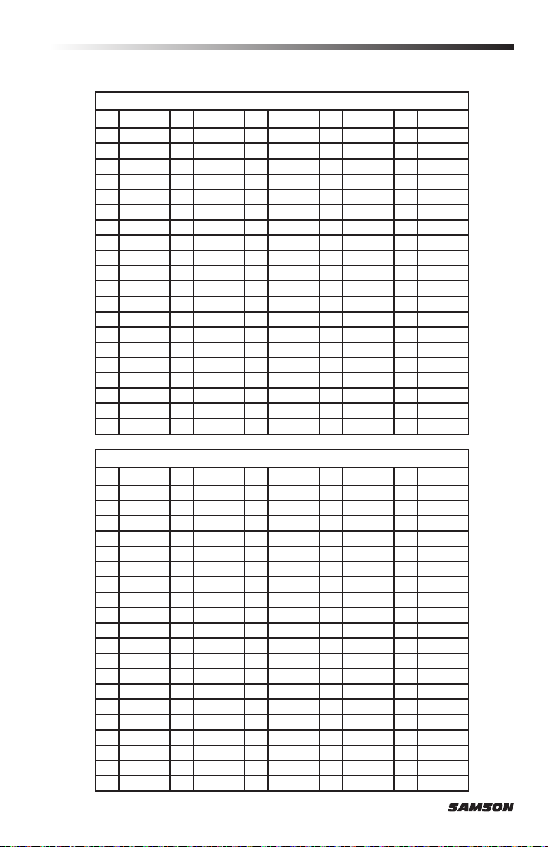
Channel Plans
CH MHz CH MHz CH MHz CH MHz CH MHz
00 470.125 20 474.625 40 479.125 60 4 83.625 80 4 88.12 5
01 470.3 50 21 474. 8 5 0 41 479. 35 0 61 483.850 81 488.350
02 470.575 22 475.075 42 479.575 62 484.075 82 4 88.575
03 470.8 00 23 475.300 43 47 9.8 00 63 48 4.300 83 488.800
04 471.0 25 24 475.5 25 44 480.025 64 484.525 84 4 89.025
05 471.250 25 475.750 45 480.250 65 48 4.75 0 85 489. 250
06 471.475 26 475.975 46 4 80 .475 66 484.975 86 4 89. 475
07 471.700 27 476.20 0 47 4 80.700 67 485.200 87 4 89.700
08 471.925 28 476.425 48 48 0.925 68 485.425 88 489.925
09 472 .150 29 476.650 49 4 81.150 69 485.650 89 490.150
10 472.375 30 476. 875 50 4 81.375 70 4 85.875 90 490.375
11 472.600 31 477.100 51 4 81.600 71 4 86.10 0 91 490.60 0
12 472.825 32 477.325 52 481.825 72 4 86.325 92 49 0.825
13 473 .050 33 477.550 53 482.050 73 486.550 93 491.0 50
14 473.2 75 34 477.775 54 482.275 74 486.775 94 491. 275
15 473.500 35 478.000 55 48 2.500 75 487.000 95 491.500
16 473.725 36 478.225 56 4 82.725 76 487. 22 5 96 491.725
17 473.95 0 37 478.450 57 4 82.95 0 77 4 87. 4 5 0 97 491.950
18 474 .175 38 478.675 58 4 8 3.175 78 487.675 98 49 2.17 5
19 4 74. 4 0 0 39 478 .900 59 4 83.400 79 4 8 7. 9 0 0 99 492.40 0
CH MHz CH MHz CH MHz CH MHz CH MHz
00 54 2.125 20 5 46.625 40 551.125 60 555.625 80 56 0.1 25
01 542.350 21 546.850 41 551. 35 0 61 555.850 81 560.350
02 542.575 22 54 7. 0 75 42 5 51.575 62 556.075 82 5 60.575
03 542.800 23 54 7. 3 0 0 43 551.80 0 63 556.300 83 560.800
04 54 3.025 24 5 4 7. 5 25 44 552.025 64 55 6.525 84 561.025
05 543.250 25 54 7. 75 0 45 552.250 65 556.750 85 561.25 0
06 5 43.475 26 547.975 46 5 52. 475 66 556.975 86 5 61.475
07 54 3.70 0 27 548.200 47 5 52.70 0 67 5 5 7. 2 0 0 87 561.70 0
08 543.925 28 548.425 48 5 52.925 68 557.425 88 5 61.925
09 5 4 4.15 0 29 548.650 49 55 3.150 69 55 7. 6 5 0 89 5 62 .150
10 544.375 30 5 48 .875 50 55 3.375 70 55 7. 8 7 5 90 562. 375
11 54 4.600 31 5 49.10 0 51 553.600 71 55 8.10 0 91 562.600
12 544.825 32 549.325 52 553.8 25 72 558.325 92 562. 825
13 545.050 33 549.550 53 554.050 73 558.550 93 563.050
14 5 45.275 34 549.775 54 55 4.275 74 558.775 94 563.275
15 545.50 0 35 550.000 55 554.500 75 559.000 95 563.500
16 5 45 .725 36 550.225 56 554 .725 76 559.225 96 563.725
17 545.950 37 550.450 57 554.950 77 559.450 97 56 3.950
18 5 4 6.17 5 38 550.675 58 555.175 78 559.675 98 5 64 .175
19 546.400 39 55 0.90 0 59 555.400 79 559.900 99 56 4.400
Group K 470– 494MHz
Group D** 542–566MHz
14
Page 15

Channel Plans
Group G* 863 –865MHz
CH MHz CH MHz CH MHz CH MHz CH MHz
00 863.050 07 864.950 14 864.800 21 8 64.650 28 864.400
01 863.550 08 8 63.10 0 15 863.300 22 864.850 29 8 64.700
02 8 63.750 09 86 3.600 16 863.150 23 863.350 30 86 4.90 0
03 864.050 10 863.800 17 863.650 24 863.200 31 86 3.400
04 864.250 11 864.10 0 18 863.850 25 863.700
05 86 4.550 12 864.300 19 8 64.15 0 26 8 63.9 00
06 8 64.750 13 864.600 20 86 4.350 27 864.200
* Not for use in the USA and Canada.
For questions regarding available channels in your area contact your local Samson distributor.
** Not for use in the EU.
AirLine 99m Wireless System 15
Page 16

Having Trouble with your AirLine Wireless System?
We can help!
CONTACT OUR SUPPORT TEAM: support@samsontech.com
Our experts can help you resolve any issues.
Follow us:
@samson @samsontech @samson_technologies
Samson Technologies
278-B Duffy Ave
Hicksville, NY 11801
Phone: 1-800-3-SAMSON
www.samsontech.com
 Loading...