

Samson Stage 55, Stage 5 Owner's Manual
AND
WIRELESS SYSTEM
TRUE DIVERSITY
WIRELESS SYSTEM
WIRELESS

Copyright 2002, Samson Technologies Corp.
Printed September 2002
Samson Technologies Corp.
575 Underhill Blvd.
P.O. Box 9031
Syosset, NY 11791-9031
Phone: 1-800-3-SAMSON (1-800-372-6766)
Fax: 516-364-3888
Table of Contents
Introduction 3
Guided Tour - SR55 Receiver Front Panel 5
Guided Tour - SR55 Receiver Rear Panel 6
Guided Tour - SR5 Receiver Front Panel 7
Guided Tour - SR5 Receiver Rear Panel 8
Guided Tour - ST5 Transmitter 9
Guided Tour - HT5 Transmitter 11
Setting Up and Using Your Stage 55 Series / Stage 5 Series System 12
Appendix B: Carrying Case 15
Specifications 16

3
Introduction
Congratulations on purchasing the Samson Stage 55 Series or Stage 5 Series Wireless
System! Although this product is designed for easy operation, we suggest you first take
some time to go through these pages so you can fully understand how we’ve implemented
a number of unique features.
Every wireless system consists of at least two components—a transmitter and a receiver,
both of which must be tuned to the same channel (that is, the same radio frequency) in
order to operate correctly.* The Samson Stage 55 Series or Stage 5 Series system you
have purchased operates in the 174.6 - 213.2 MHz frequency range and contains either a
SR55 or SR5 receiver as well as one of the following transmitters: a ST5 belt-pack
transmitter (for lavaliere microphone or headset applications); a ST5 belt-pack transmitter
(for instrument applications); or a HT5 hand-held microphone transmitter. For convenience
and security, the Stage 55 Series and Stage 5 Series system is packaged in a custom
impact-resistant polypropylene plastic carrying case that provides room for all components
(see Appendix B for more information).
The ST5L beltpack transmitter provides a locking 3.5 mm mini-phone jack for connection to
the various Stage series transmitters including:
LM5 - Lavaliere condenser microphone
HS5 - Headset condenser microphone
GC5 - Heavy-duty Guitar/Instrument cable
The HT5 hand-held microphone transmitter is equipped with the Samson Q7 neodymium
dynamic microphone element.
* Your receiver and transmitter have been factory preset to utilize the same channel.
The SR5 receiver provided with the STAGE 5 Series wireless system utilizes non-diversity
technology, incorporating a single antenna for ease of use and minimal cost. The SR55
receiver provided with the Stage 55 Series system utilizes an advanced technology
called “Diversity,” whereby a single chassis houses two antennas (called “Antenna A” and
“Antenna B”) and a receiver circuit. An advanced circuit design continuously scans RF signals from the two antennas and determines which one has the clearest and strongest
reception, automatically (and silently) switching that signal to the receiver. This allows you
to maintain the wireless communication link over a much broader area range than would be
allowed by a receiver utilizing a single antenna and also virtually eliminates multipath
dropouts, interference and phase cancellation problems. In addition, special sample-andhold linking circuitry ensures that correct phase correlation is maintained at all times, with
no noise or pops during antenna switching. The result is performance which exceeds that
of conventional non-diversity systems and the highest quality audio fidelity available in any
wireless system. Finally, the provision of a noise reduction circuit produces crystal-clear
sound with minimized background noise and hiss.

4
Introduction
In this manual, you’ll find a more detailed description of the features of your Stage 55
Series or Stage 5 Series system, as well as a guided tour through all components, stepby-step instructions for setting up and using your system and full specifications. If your
Stage 55 Series or Stage 5 Series system was purchased in the United States, you’ll also
find a warranty card enclosed—don’t forget to fill it out and mail it! This will enable you to
receive online technical support and will allow us to send you updated information about
other Samson products in the future. If your Stage 55 Series or Stage 5 Series system
was purchased outside of the United States, contact your local distributor for warranty
details.
SPECIAL NOTE for U.S. purchasers: Should your Stage 55 Series or Stage 5 Series system ever require servicing, a Return Authorization number (RA) is necessary. Without this
number, the unit will not be accepted. Please call Samson at 1-800-372-6766 for a
Return Authorization number prior to shipping your unit. Please retain the original packing
materials and, if possible, return the unit in its original carton and packing materials.
If your Stage 55 Series or Stage 5 Series system was purchased outside of the United
States, contact your local distributor for servicing information.
5
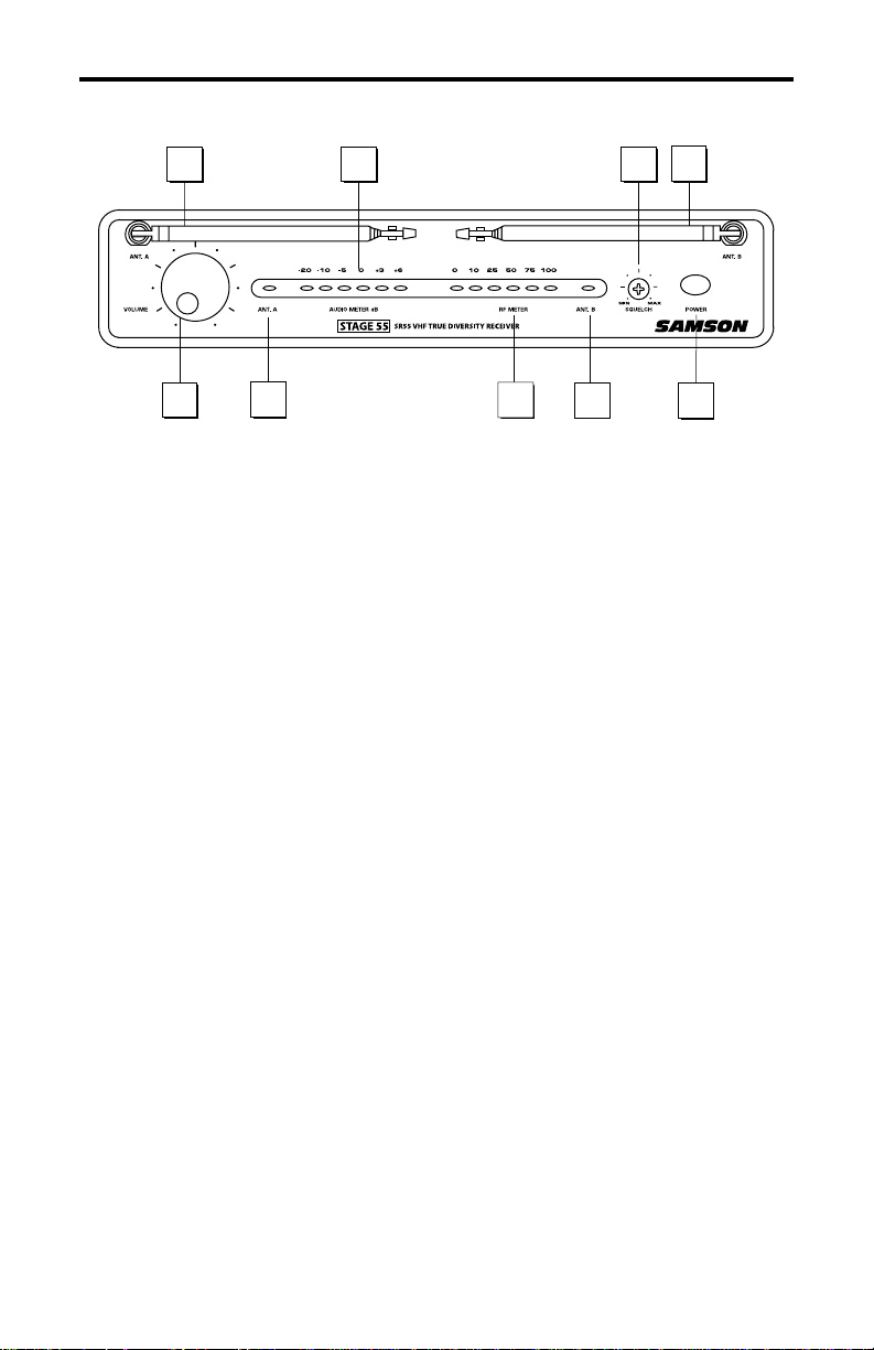
Guided Tour - SR55 Front Panel
1: Antennas (A and B) - The antenna mountings allow full rotation for optimum
placement. In normal operation, both Antenna A (the antenna on the left) and Antenna B
(the antenna on the right) should be placed in a vertical position. Both antennas can be
folded inward for convenience when transporting the SR55. See the “Setting Up and Using
Your Stage 55 Series / Stage 5 Series System” section on page 12 in this manual for more
information about antenna positioning.
2: Volume control - This knob sets the level of the audio signal being output through both
the balanced and unbalanced output jacks on the rear panel. Reference level is obtained
when the knob is turned fully clockwise.
3: Audio Meter - This “ladder” display (similar to the VU bar meter used on audio devices)
indicates the strength of the incoming audio signal. When the “0” segment is lit, the incoming signal is optimized at unity gain; when the “+6” segment is lit, the signal is overloading.
When only the left-most “-20” segment is lit, the incoming signal is at just 10% of optimum
strength. If no segments are lit, little or no signal is being received. See the “Setting Up
and Using Your Stage 55 Series / Stage 5 Series System” section on page 12 in this manual for more information.
4: Squelch control - This control determines the maximum range of the SR55 before
audio signal dropout. Although it can be adjusted using the supplied plastic screwdriver, it
should normally be left at its factory setting. See the “Setting Up and Using Your Stage 55
Series / Stage 5 Series System” section on page 12 in this manual for more information.
5: ANT A/B LEDs - When signal is being received, one of these will be lit yellow, showing
you whether the (left) “A” or (right) “B” antenna is currently being used. The SR55 constantly scans its two antennas and automatically selects whichever is receiving the
strongest, clearest signal. This Diversity switching is completely inaudible, but it effectively
increases overall range while virtually eliminating potential interference and phase cancellation problems.
6: RF Meter - This “ladder” display (similar to the VU bar meter used on audio devices)
indicates the strength of the incoming radio signal. When the “100%” segment is lit, the
incoming RF signal is fully modulated and at optimum strength. When only the second
most left-most “10%” segment is lit, the incoming signal is at just 10% of optimum strength.
If no segments are lit, little or no signal is being received. See the “Setting Up and Using
Your Stage 55 Series / Stage 5 Series System” section on page 12 in this manual for more
information.
7: Power switch - Use this to turn the SR55 power on and off.
1
2
5 5
3 4
6
1
7

6
Guided Tour - SR55 Rear Panel
1: DC input - Connect the supplied 12 volt, 250 mA power adapter here, using the strain
relief as shown in the illustration below. WARNING: The substitution of any other kind of
power adapter can cause severe damage to the SR55 and will void your warranty.
2: Balanced output* - Use this electronically balanced low impedance (600 Ohm) XLR
jack when connecting the SR55 to professional (+4) audio equipment. Pin wiring is as
follows: Pin 1 ground (shield), Pin 2 high (hot), and Pin 3 low (cold).
3: Audio Output Level switch - Sets the audio output level attenuation of the balanced
output (see #4 below) to -20 dBm (line level) or -40 dBm (mic level). See the “Setting Up
and Using Your Stage 55 Series / Stage 5 Series System” section on page 12 in this manual for more information.
4: Unbalanced output* - Use this unbalanced high impedance (5K Ohm) 1/4" jack when
connecting the SR55 to consumer (-10) audio equipment. Wiring is as follows: tip hot,
sleeve ground.
* If required, both the unbalanced and balanced outputs can be used simultaneously.
Using the strain relief: Gather up a loop of wire and pass it through the strain relief,
then pass the adapter plug through the loop in order to create a knot.
1
2
3
-
4
 Loading...