

Page 1
FOUNDATION
TM
FIELDBUS Positioner
Type 3787
Fig. 1 ⋅Type 378 7
Mounting and
Operating Instructions
EB 8383-1 EN
Firmware R 1.4x/K 1.4x
Edition November 2004
Page 2

Contents Page
1 Design and principle of operation
. . . . . . . . . . . . . . . . . . . . . . 8
1.1 Optional limit switches . . . . . . . . . . . . . . . . . . . . . . . . . . . . 8
1.2 Communication . . . . . . . . . . . . . . . . . . . . . . . . . . . . . . . 8
2 Attachment to the control valve
. . . . . . . . . . . . . . . . . . . . . . . 10
2.1 Direct attachment to Type 3277 Actuator . . . . . . . . . . . . . . . . . . . 10
2.2 Attachment acc. to IEC 60534-6 . . . . . . . . . . . . . . . . . . . . . . . 14
2.2.1 Mounting sequence . . . . . . . . . . . . . . . . . . . . . . . . . . . . . 14
2.2.2 Presetting the valve travel . . . . . . . . . . . . . . . . . . . . . . . . . . . 16
2.3 Attachment to rotary actuators . . . . . . . . . . . . . . . . . . . . . . . . 17
2.3.1 Mounting the lever with feeler roll . . . . . . . . . . . . . . . . . . . . . . . 18
2.3.2 Mounting the intermediate piece . . . . . . . . . . . . . . . . . . . . . . . 18
2.3.3 Aligning and mounting the cam disk . . . . . . . . . . . . . . . . . . . . . 20
2.3.4 Reversing amplifier for double-acting actuators . . . . . . . . . . . . . . . . 22
2.4 Fail-safe action of the actuator . . . . . . . . . . . . . . . . . . . . . . . . 22
3 Connections
. . . . . . . . . . . . . . . . . . . . . . . . . . . . . . . . . 24
3.1 Pneumatic connections . . . . . . . . . . . . . . . . . . . . . . . . . . . . 24
3.1.1 Pressure gauge . . . . . . . . . . . . . . . . . . . . . . . . . . . . . . . 24
3.1.2 Supply air pressure . . . . . . . . . . . . . . . . . . . . . . . . . . . . . 25
3.2 Electrical connections . . . . . . . . . . . . . . . . . . . . . . . . . . . . 25
3.2.1 Establishing communication . . . . . . . . . . . . . . . . . . . . . . . . . 28
4Operation
. . . . . . . . . . . . . . . . . . . . . . . . . . . . . . . . . . 29
4.1 LEDs . . . . . . . . . . . . . . . . . . . . . . . . . . . . . . . . . . . . . 29
4.2 Write protection and simulation switches . . . . . . . . . . . . . . . . . . . 30
4.3 Activate/deactivate forced venting function . . . . . . . . . . . . . . . . . . 30
4.4 Default setting . . . . . . . . . . . . . . . . . . . . . . . . . . . . . . . . 30
4.4.1 Adjusting mechanical zero . . . . . . . . . . . . . . . . . . . . . . . . . . 30
4.4.2 Initialization . . . . . . . . . . . . . . . . . . . . . . . . . . . . . . . . . 31
4.5 Operation via TROVIS-VIEW . . . . . . . . . . . . . . . . . . . . . . . . . 33
4.5.1 Initialization . . . . . . . . . . . . . . . . . . . . . . . . . . . . . . . . . 33
4.5.2 Testing the control valve . . . . . . . . . . . . . . . . . . . . . . . . . . . 34
4.6 Setting the inductive limit switches . . . . . . . . . . . . . . . . . . . . . . 34
Contents
2
EB 8383-1 EN
Page 3

5 Maintenance
. . . . . . . . . . . . . . . . . . . . . . . . . . . . . . . 35
6 Servicing explosion-protected versions
. . . . . . . . . . . . . . . . . . . 35
7 Parameter description
. . . . . . . . . . . . . . . . . . . . . . . . . . . 36
7.1 General . . . . . . . . . . . . . . . . . . . . . . . . . . . . . . . . . . 36
7.2 Device Description (DD) . . . . . . . . . . . . . . . . . . . . . . . . . . 36
7.3 Notes on the parameters . . . . . . . . . . . . . . . . . . . . . . . . . . 36
7.3.1 Legends assigned to the parameters . . . . . . . . . . . . . . . . . . . . . 37
7.3.2 Notes on parameter storage classes S, N and D . . . . . . . . . . . . . . . 37
7.4 Block structure . . . . . . . . . . . . . . . . . . . . . . . . . . . . . . . 38
7.4.1 Resource Block . . . . . . . . . . . . . . . . . . . . . . . . . . . . . . 40
7.4.2 Transducer Block . . . . . . . . . . . . . . . . . . . . . . . . . . . . . . 46
7.4.3 Function Blocks . . . . . . . . . . . . . . . . . . . . . . . . . . . . . . 57
7.4.3.1 Analog Output Function Block . . . . . . . . . . . . . . . . . . . . . . . 57
Parameters of the Analog Output Function Block . . . . . . . . . . . . . . . 59
7.4.3.2 PID Function Block (PID controller) . . . . . . . . . . . . . . . . . . . . . . 65
Parameters of the PID Function Block . . . . . . . . . . . . . . . . . . . . 67
7.5 Other parameters . . . . . . . . . . . . . . . . . . . . . . . . . . . . . 78
7.5.1 Stale counter . . . . . . . . . . . . . . . . . . . . . . . . . . . . . . . . 78
7.5.2 Link objects . . . . . . . . . . . . . . . . . . . . . . . . . . . . . . . . 78
7.5.3 LAS capabilities . . . . . . . . . . . . . . . . . . . . . . . . . . . . . . 78
8Diagnostic messages
. . . . . . . . . . . . . . . . . . . . . . . . . . . . 79
8.1 Messages of the XD_ERROR_EXT parameter (Transducer Block) . . . . . . . 79
8.2 Messages of the XD_ERROR parameter (Transducer Block) . . . . . . . . . . 80
8.3 Messages of the SELF_CALIB_STATUS parameter (Transducer Block) . . . . . 81
Dimensional drawing . . . . . . . . . . . . . . . . . . . . . . . . . . . 82
EC Type Examination Certificate . . . . . . . . . . . . . . . . . . . . . . 83
CSA/FM certification . . . . . . . . . . . . . . . . . . . . . . . . . . . . 90
Contents
EB 8383-1 EN
3
Page 4

Safety instructions
The device may only be assembled, started up, and operated by experienced
personnel familiar with this product.
In these mounting and operating instructions, the term "experienced personnel" refers to individuals who are able to evaluate the responsibilities assigned
to them as well as recognize potential hazards due to their specialized training, knowledge, and experience as well as their special knowledge of the relevant standards.
Explosion-protected versions of this device may only be operated by personnel who have undergone special training or instructions, or who are authorized to work on explosion-protected devices in hazardous areas.
Any hazards which could be caused by the process medium, the operating
pressure, the signal pressure and moving parts of the control valve, must be
prevented by means of appropriate measures.
Should inadmissible motions or forces be produced in the pneumatic actuator
as a result of the level associated with the supply air pressure, these must be
restricted by means of a suitable pressure reducing station.
Proper shipping and appropriate storage of the device are assumed.
Note:
Devices with the CE mark meet the requirements specified in the Directive
94/9/EC and the Directive 89/336/EEC.
The Declaration of Conformity can be viewed and downloaded from the
SAMSON website at www.samson.de.
Modifications of positioner firmware in comparison to previous versions
Previous New
Positioner R 1.41 R 1.42
Correction in the zero calibration activated over software
communication
4
EB 8383-1 EN
Page 5

Firmware modifications
Communication
K1.00 K1.20
Version compatible with user interface software version number:
Fisher-Rosemount DeltaV in version 5.1 or higher
National Instruments Fieldbus Configurator in version 2.3 or
higher.
All host systems certified by the Fieldbus Foundation
Alteration to default values of the following parameters:
AO Function Block CHANNEL, PID Function Block GAIN,
PID Function Block RESET, PID Function Block BYPASS
Resource Block parameter extended:
BLOCK_ERROR, page 40
Transducer Block parameters changed/extended:
BLOCK_ERR, page 46.
Communication
K 1.00 K1.31
The output parameters of the function blocks can be
interconnected within a device and with blocks in other devices at
the same time. In the previous version, it was only possible to
either interconnect function blocks within a device or with blocks
in other devices.
An Output Failure in BLOCK_ERR of the AO Function Block
generates a Block Alarm.
The automatic resetting control loop monitor (previously not
automatic resetting) is evaluated for the control loop error
indication via LED or the message "Calibration Error". This means
this alarm or message is automatically reset as soon as the control
loop monitor cannot find an error anymore.
Communication
K 1.31 K1.40
The default value for RESET in the PID Block has been changed
from 0 to 3402823466 x 10
38
(maximum possible value). The
integral-action component of the PID is ineffective at this value as
well as at 0. On switching over the operating mode from MAN to
AUTO, a smooth switchover is achieved.
EB 8383-1 EN
5
Page 6
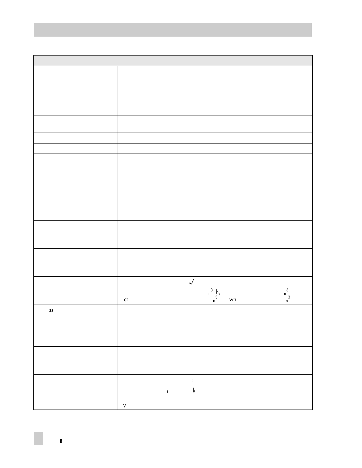
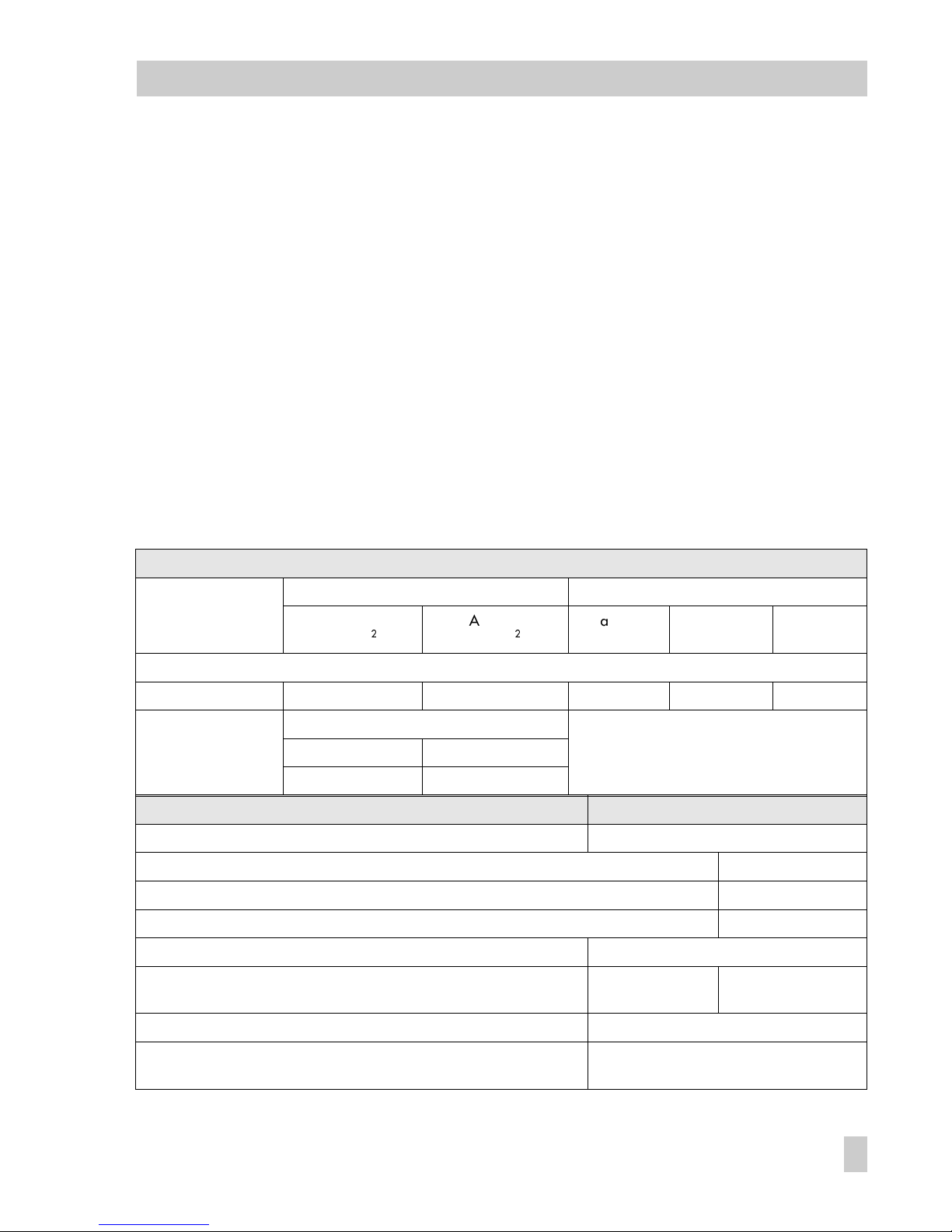
Technical data
Positioner
Travel
Direct attachment to Type 3277
Attachment acc. to IEC 60534-6
Adjustable
5 to 30 mm
5 to 255 mm or 30 to 120° for rotary actuators
Bus connection Fieldbus interface as per IEC 61158-2, bus-powered
Physical Layer Class: 113 (not explosion-protected version) and 111 (Ex-version)
Field device according to FM 3610 entity and FISCO.
Per m issib le o perati ng v oltage 9 to 32 V DC; The speci f icatio ns i n the EC Type E xamina tion Certif i cate addit ionally
apply for explosion-protected devices. Power supply over bus cable
Max. operating current 13 mA
Additional current in case of fault 0 mA
Supply air Supply air from 1.4 to 6 bar (20 to 90 psi);
Air quality as per ISO 8573-1: Max. particle size and density: Class 4;
Oil co nt ents: C la ss 3; Pr es sure de w p oint: C la ss 3
Signal pressure (output) 0 bar up to the pressure of the supply air
Characteristic, adjustable
Deviation
Globe valve: linear, equal percentage, reverse equal percentage,
SAMSON butterfly valve: linear, equal percentage
VETEC plug rotary valve: linear, equal percentage
≤1 %
Dead band
(based on rated travel/angle
Adjustable from 0.1 to 10.0 % , default 0.5 %
Resolution (internal measurement) < 0.05 %
Tran sit time re quired For v al ve tra ns it time up to 75 s
Set point ramp for exhaust and supply air separately adjustable
Operating direction Reversible, setting by software
Air consumption Independent of supply air <90l
n
/h
Air s upply A ctuat or f illed: wh en Δp = 6 bar 9.3 m
n
3
/h, when Δp = 1.4 bar 3.5 m
n
3
/h
Actu at or vented : w hen Δp = 6 bar 15.5 m
n
3
/h, when Δp = 1.4 bar 5.8 m
n
3
/h
Permissible ambient temperature 40 to 80 °C
The specifi cation s in t h e EC Typ e Examin ation Certif icate addi tionally app ly f o r
explosion-protected devices
Effects Temperature: ≤0.15 %/10 K, supply air: none,
Vibrations: none up to 250 Hz and 4 g
Deg re e o f prote ct io n IP 65 us ing fil te r check va lve inc luded
Electromagnetic compatibility Requirements acc. to EN 61000-6-2, EN 61000-6-3 and
NAMUR Recommendations NE 21 are met
Bin ar y in pu t Inte rn al powe r s upply 5 V DC , R
i
= 100 kΩ for a la rm func ti on
Forced venting
(activated over an internal switch)
Input 6 to 24 V DC, R
i
approx. 6 kΩ at 24 V D C ( depend in g on volt age)
Switching point for "1" signal ≥ 3 V, switc hi ng poin t f or "0" sign al only at 0 V,
K
V
0.17
6
EB 8383-1 EN
Page 7
Versions
Accessories
Inductive limit switches Two Type SJ 2 SN Proximity Switches for connection to a switching amplifier acc. to
EN 60947-5-6
Communication
Data transmission In accordance with FOUNDATION
TM
Fieldbus specification
Communication Profile Class: 31 PS, 32: Interoperability Test System (I TS) Revision 4.0
Materials
Case Die -c as t alumi num, chr om ized an d p lastic -c oated
External parts Stainless steel 1.4571 and 1.4301
Weigh t Appr ox 1. 3 kg
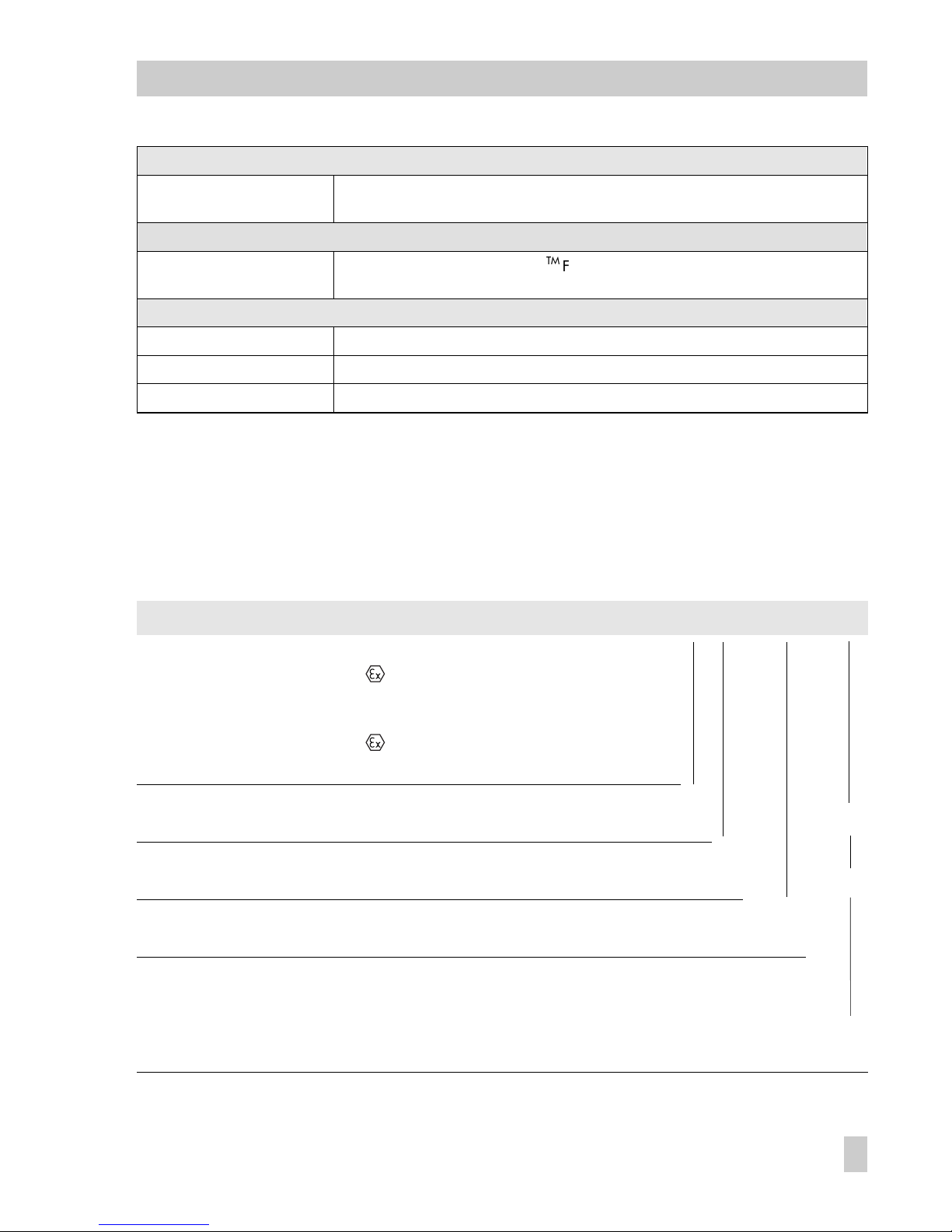
Versions of the positioner
Model
3787 -
XXX
0
X3X
Explosion protection Without
II 2 G EEx ia IIC T6/
II 2 D IP 65 T 80 °C acc. to ATEX
Ex ia FM/CSA
II 3 G EEx ia IIC T6/
II 3 D IP 54 T 80 °C acc. to ATEX
0
1
3
8
Accessories Limit switches Without
2 inductive
0
22
Forced venting Without (deactivated)
With (activated)
0
12
Pneumatic
connections
NPT 1/4- 18
ISO 228/1-G 1/4
1
2
Electric connections Cable gland M20 x 1.5
Nickel-plated brass
Quantity: 1
2
1
2
EB 8383-1 EN
7
Page 8

1 Design and principle of operation
The digital positioner compares the reference variable, which is cyclically transmitted over the FOUNDATION
TM
Fieldbus,
with the travel or opening angle of the control valve. It then delivers a corresponding
signal pressure. It is suitable for attachment
to linear and rotary actuators.
The Type 3787 Positioner communicates as
per FOUNDATION
TM
Fieldbus specification
with field devices, programmable logic controllers and process management systems.
An integrated PID Function Block allows the
control of required process variables directly in the field.
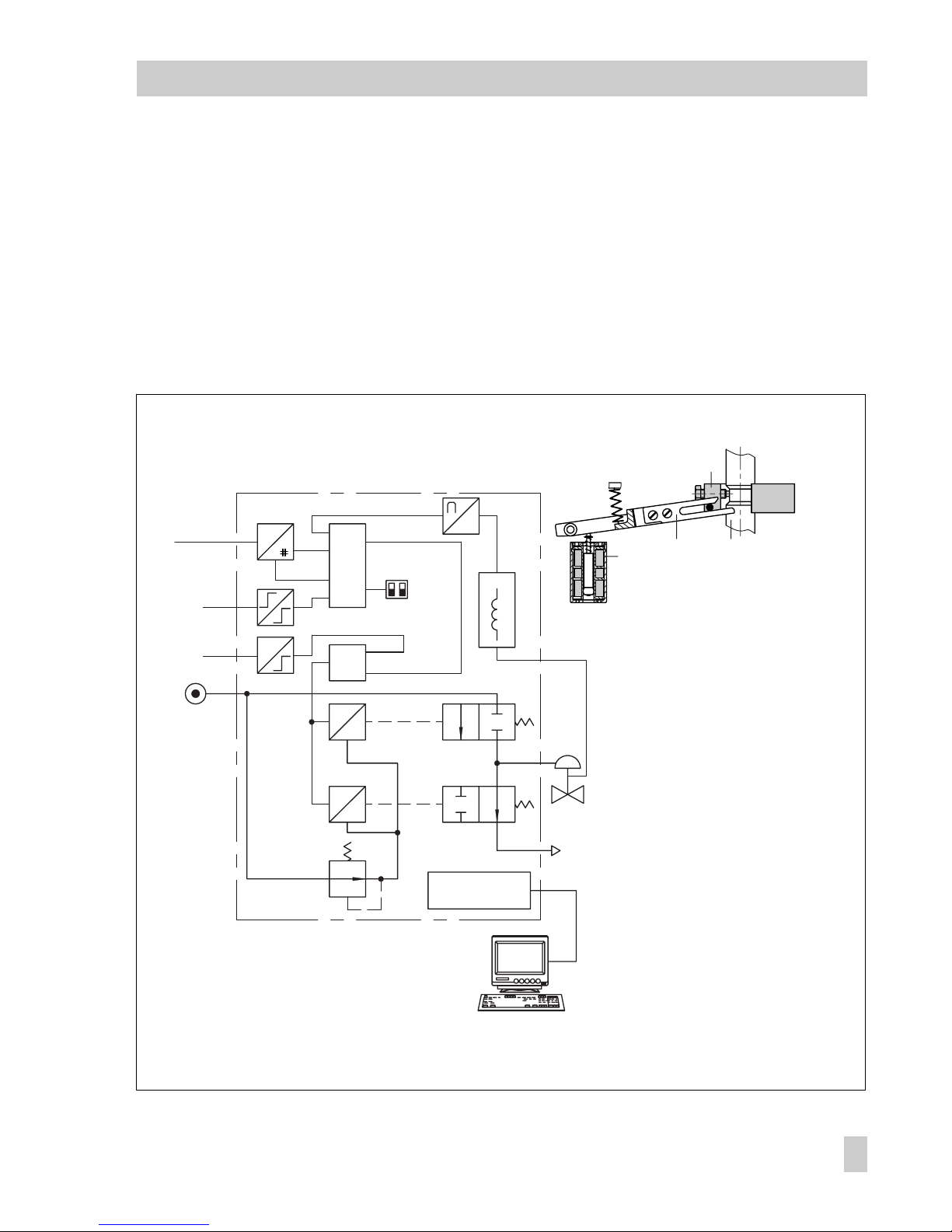
The travel of the control valve is picked up
by the inductive displacement sensor (1)
and supplied to the microcontroller (2) via a
converter.
The microcontroller compares the travel
with the reference variable and controls the
two pneumatic 2/2-way on-off valves (3, 4)
when a system deviation occurs. The on-off
valves fill (3) or vent (4) the pneumatic actuator via corresponding amplifiers corresponding to the system deviation.
Two LEDs on the inside of the cover indicate
the operating status of the positioner.
The positioner is equipped with a standard
binary input over which any process information can be signaled via the FOUNDATION
TM
Fieldbus.
The write protection switch (6) located on
the inside of the cover prevents stored configuration data from being overwritten.
Forced venting:
The positioner is controlled over a 6 to 24 V
signal which causes the corresponding signal pressure to be applied to the actuator. If
the voltage signal drops, the signal pressure
is shut off and the actuator is vented. The
control valve moves to its fail-safe position
regardless of the output variable issued by
the microcontroller.
1.1 Optional limit switches
Limit switches can be retrofitted to the standard positioner.
Two proximity switches can be used for failsafe circuits to indicate the valves end positions.
1.2 Communication
The positioner is completely controlled via
digital signal transmission according to the
FOUNDATION
TM
Fieldbus specification
based on the E EN 50170/A1 draft. Data
is transmitted as bit synchronous current
modulation at a transmission rate of
31.25 kbit/s over twisted pairs according
to IEC 61158-2.
Configuration with TROVIS-VIEW
The positioner can be configured using the
SAMSON Configuration and Operator Interface, TROVIS-VIEW.
To configure the positioner, connect its additional
SERIAL INTERFACE
to the RS-232 interface of a PC using an adapter cable.
After adapting the positioner to the process
requirements, TROVIS-VIEW enables the
process to be controlled online.
8
EB 8383-1 EN
Design and principle of operation
Page 9
Configuration with NI-FBUSTM Configurator
The positioner can also be configured using
the NI-FBUS
TM
Configurator from National
Instruments.
An interface card installed in a PC is required to connect it to FOUNDATION
TM
Fieldbus.
The NI-FBUS
TM
Configurator can be used to
configure the whole FOUNDATION
TM
Fieldbus network.
Fig. 2 ⋅Functional diagram
e
p
3
4
2
9
7
8
6
1
G
μC
&
IEC 61158-2
e
p
G
Fieldbus
Foundation
8
TROVIS
VIEW
11
10
1
12
u
13
Forced
venting
Binary
input
Supply
air
Exhaust
air
Serial Interface
1 Inductive displacement sensor
2 Microcontroller
3 On-off valve for supply air
4 On-off valve for exhaust air
5 Microcontroller
6 Switches for write protection and
simulation mode
7 Binary input
8 Forced venting
9 IEC 61158-2 interface module
10 Actuator stem
11 Lever
12 Clamp
13 Configuration interface
EB 8383-1 EN
9
Design and principle of operation
Page 10

2 Attachment to the control valve
The positioner can be attached either directly to a SAMSON Type 3277 Actuator
or to control valves with cast yokes or rodtype yokes according to IEC 60534-6
(NAMUR).
In connection with an intermediate piece,
the positioner can also be attached to rotary actuators.
Since the standard positioner is delivered
without accessories, please refer to the
tables for required mounting parts and their
order numbers.
Note!
For fast control valves with small travel volumes (transit time < 0.6 sec.), replace the filter in the signal pressure output with a
screw-in throttle, if necessary, to improve
the control properties. See also sections
2.1, 2.2 and 2.3.
Important!
The positioner does not have its own venting plug, instead vented air has to escape
through venting plugs located on the mounting parts (see Figs. 3, 5 and 7).
A filter check valve for the vented air is included in every positioner delivery (under
the transparent protective cap on the back
of the positioner). Replace the standard venting plug included in the accessories with
this filter check valve. This is the only way to
achieve the degree of protection IP 65 by
preventing dirt and moisture from entering
the device.
2.1 Direct attachment to Type
3277 Actuator
The necessary accessories are listed in the
Tables 1, 2 and 3 on page 13
.
When looking at the signal pressure connection or the switchover plate (actuator 120
cm
2
), the positioner must be attached to the
left side of the actuator.
The
arrow
on the black cover of the case
(Fig. 11) should point
towards the dia-
phragm chamber
.
Exception:
Control valves in which the plug
closes the seat area when the actuator stem
retracts. In this case, the positioner has to
be attached to the right side of the actuator
and the arrow points away from the diaphragm chamber.
1. Screw the clamp (1.2) to the actuator
stem, ensuring that the fastening screw
is located in the groove of the actuator
stem.
2. Screw the assigned pick-up lever D1 or
D2 to the transmission lever of the positioner.
3. Fasten the distance plate (15) with seal
pointing towards the actuator yoke.
4. Place the positioner on the plate so that
the lever D1 or D2 slides centrally over
the pin of the clamp (1.2). Then screw
tight to the distance plate (15).
5. Mount cover (16).
Actuators with 240, 350 and 700 cm
2
6. Check whether the tongue of the seal
(17) is properly aligned at the side of
the connection block (Fig. 3, center)
10
EB 8383-1 EN
Attachment to the control valve
Page 11
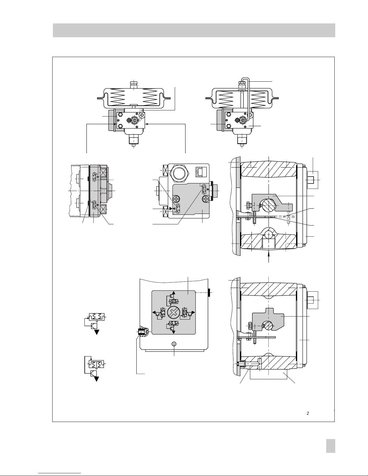
Actuator stem retracts
Side view of connection block
with seal
(ne w
) with switch plate (old)
Fig. 3 ⋅Attachment and signal pressure connection for Type 3277 Actuators (top) and 3277-5 with 120 cm (bottom)
SUPPLY
1817 19
1.2
D2
D1
17
16
15
1.2
16
17
15
Actuator stem retracts
Internal signal pressure
connection
Signal pressure tube
1.2 Clamp
D1 Lever
D2 Lever
15 Distance plate
16 Cover
17 Seal
18 Cover plate
19 Switch plate
Signal pressure bore
Connection block
Marking
Marking
Symbol "actuator
stem extends"
"Actuator stem
retracts"
Switchover
plate
Switchover plate
Signal pressure input
Signal pressure
input with brass
throttle, if required
Actuator stem extends
Ventin g
Actuator stem extends
EB 8383-1 EN
11
Attachment to the control valve
Page 12

with the actuator symbol "actuator stem
extends" or "actuator stem retracts" to
match the actuator version used.
If not, remove the three fastening
screws and the cover plate (18), turn
the seal (17) by 180° and reinsert it.
When the
old
connection block is used,
turn the switch plate (19) to align the actuator symbol with the arrow.
7. Place the connection block with its seal
rings on the positioner and actuator
yoke and screw it tight using the fastening screw.
For actuators with "actuator stem retracts", additionally attach the readymade signal pressure line.
Actuator with 120 cm
2
For the Type 3277-5 Actuator with 120 cm
2
effective diaphragm area, the signal pressure is transmitted to the diaphragm chamber via the switchover plate (Fig. 3 bottom).
For a rated travel of 7.5 mm, a brass
throttle (see Accessories table on page 13)
must be pressed into the seal located in the
signal pressure input on the actuator yoke.
For a rated travel of 15 mm, this is only required when the supply pressure exceeds
4 bar.
6. Remove the screw plug on the rear of
the positioner case and seal the signal
pressure output (Output 38) with the
plug from the accessories.
7. Mount the positioner so that the bore in
the distance plate (15) is aligned with
the seal located in the bore of the actuator yoke.
8. Align the switchover plate with the
corresponding symbol for left attachment and screw the plate to the actuator yoke.
Important!
If, in addition to the positioner, a solenoid
valve or a similar device is attached to the
120 cm
2
actuator, the rear M3 screw must
not be removed. In this case, the signal
pressure has to be fed from the signal pressure output to the actuator via the required
connecting plate (see Table 2). The switchover plate is no longer required.
Note!
For faster control valves with a transit time
less than 0.6 seconds, replace the filter in
the signal pressure output (output 38) with a
screw-in throttle (see Accessories table), if
necessary.
Filling the diaphragm chamber with air
If the Type 3277 Actuators diaphragm
chamber must be filled with air exhausted
from the positioner, the diaphragm chamber (for version with "actuator stem extends") can be connected to the connection
block using a tube (see Table 3). To do
this, first remove the screw plug from the
connection block.
For the Type 3277-5 Actuator with "actuator stem retracts", the air exhausted from
the positioner is constantly supplied to the
diaphragm chamber through an internal
bore.
12
EB 8383-1 EN
Attachment to the control valve
Page 13
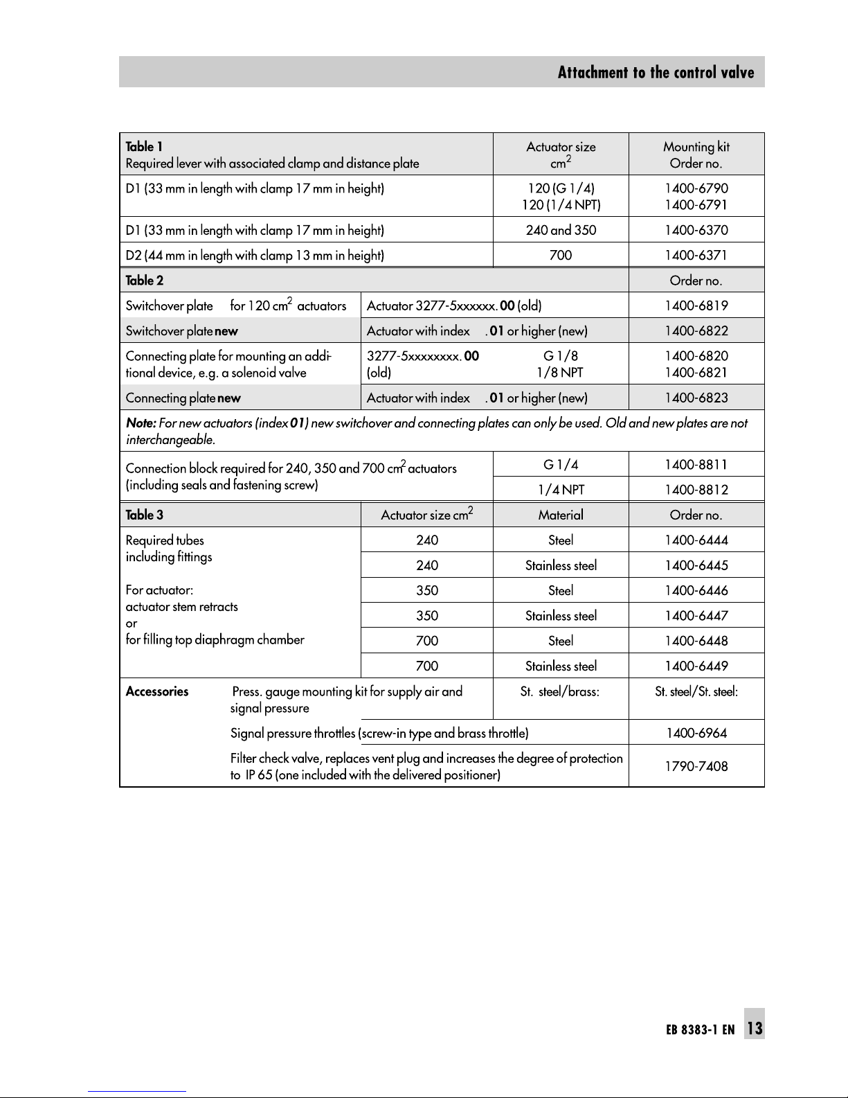
1402-0938 1402-0939
1)
Order with every pressure gauge kit: 2 restrictions (1790-6121)
1)
Page 14

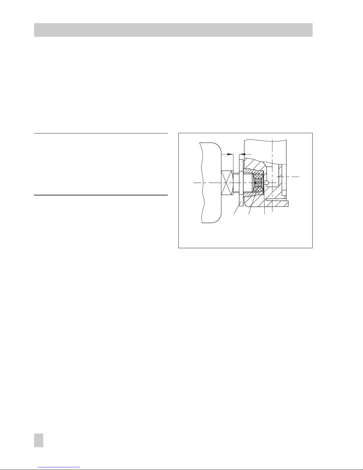
2.2 Attachment acc. to IEC 60534-6
The positioner is attached according to
NAMUR as shown in Fig. 4 using an adapter housing. The valve travel is transmitted
via the lever (18) and the shaft (25) to the
bracket (28) in the adapter housing and
then to the coupling pin (27) located on the
lever of the positioner.
To attach the positioner, you will require the
mounting parts listed in Table 4. Which
lever should be used depends on the rated
valve travel.
The positioner must be attached to the
adapter housing with the
arrow
on the
black case cover pointing
away from the
diaphragm actuator
towards the valve.
Exception: Control valves in which the plug
closes the seat area when the actuator stem
retracts. In this case, the arrow must point
towards the diaphragm actuator.
If the adapter housing cannot be mounted
between
the actuator and valve (e.g. because the actuator is from another manufacturer), the
arrow
on the case cover must
point towards the valve!
Note!
For faster control valves with a transit time
less than 0.6 seconds, replace the filter in
the signal pressure output (output 38) with a
screw-in throttle (see Accessories table).
2.2.1 Mounting sequence
Refer to Tables 4 and 5 on page 16 for required mounting parts.
Note!
Prior to mounting the parts, apply signal
pressure to the actuator so that the valve is
set to 50 % of its travel. This is the only way
to make sure that the lever (18) and bracket
(28) are exactly aligned.
Control valve with cast yoke
1. Use countersunk screws to fix the plate
(20) to the coupling which connects the
plug stem and actuator stem. With actuators 2100 and 2800 cm
2
, use addi-
tional mounting bracket (32).
2. Remove rubber plug from the adapter
housing and fasten the housing to the
NAMUR rib with hexagon head screw.
Control valve with rod-type yoke
1. Screw plate (20) to the follower clamp
of the plug stem.
2. Screw the studs (29) into the adapter
housing.
3. Place the housing with the plate (30) on
either the right or left side of the valve
stem and fasten tight using the nuts
(31). On doing so, make sure the housing is aligned at a height which will
still allow the lever (18) to be attached
horizontally.
4. Screw the pin (19) into the center row
of holes in the plate (20) and lock into
place so that it is located approximately
above the correct lever marking (1 to 2)
14
EB 8383-1 EN
Attachment to the control valve
Page 15
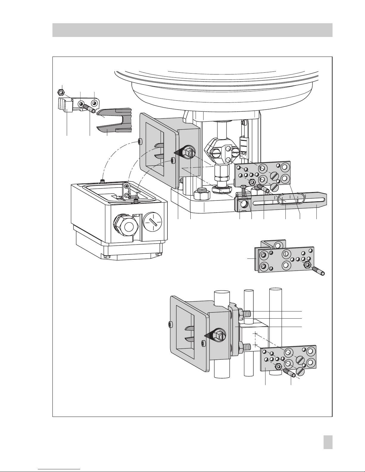
Fig. 4 ⋅Attachment according to IEC 60534-6 (NAMUR)
2
1,5
1
2826
AB
24 25 22
32
31
20 19
19 21 2023 18
27b
27a
29
30
Attachment to
NAMUR rib
Mounting position
Attachment to rod
18 Lever N1, N2
19 Pin
20 Plate
21 Clamp
22 Clamping plate
23 Screw
24 Pointer
25 Shaft
26 Lever of positioner
27a Transmission pin
27b Lock nut
28 Bracket
29 Studs
30 Plate
31 Nuts
32 Mounting bracket
EB 8383-1 EN
15
Attachment to the control valve
Page 16
for the assigned travel, see Table 5.
Intermediate values must be calculated.
Move the clamp (21) beforehand to
clasp the pin.
5. Measure the distance from the middle
of the shaft (25) to the middle of the pin
(19). This value must be entered later
when the positioner is being configured.
2.2.2 Presetting the valve travel
1. Adjust the shaft (25) in the adapter
housing so that the black pointer (24) is
aligned with the casted marking on the
adapter housing.
2. Screw the clamping plate (22) tight in
this position using the screw (23).
3. Screw the coupling pin (27) into the positioner lever (26) on the side with the
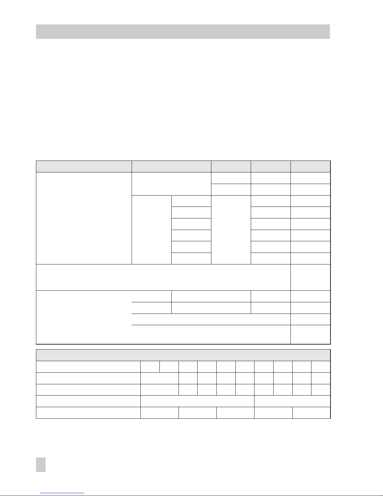
Table 4
Attach. acc. to IEC 60534-6 Control valve Travel in mm With lever Order no.
NAMUR mounting kit
See Fig. 4 for parts
Valve w it h cast yoke
7.5 to 60 N1 (125 mm) 1400-6787
30 to 120 N2 (212 mm) 1400-6789
Valve with
rod-type
yoke with
rod diameter
in mm
20 to 25 N1 1400-6436
20 to 25 N2 1400-6437
25 to 30 N1 1400-6438
25 to 30 N2 1400-6439
30 to 35 N1 1400-6440
30 to 35 N2 1400-6441
Attachment to Fisher and Masoneilan linear actuators
(one ea ch of bo th mo un ting ki ts is need ed per one ac tuator )
1400-6771
and
1400-6787
Accessories
Press. gauge mounting block G 1/4: 1400-7458 1/4 NPT: 1400-7459
Pressure gauge set St. st./brass: 1400-6957 St. st./St. st.: 1400-6958
Signal pressure throttles (screw-in type and brass throttle) 1400-6964
Filter check valve, replaces vent plug and increases the degree of protection
to IP 65 (one included with the delivered positioner)
1790-7408
Table 5
Attachment according to IEC 60534-6
Travel mm *) 7.51515303060306060120
Pin on mark *) 1 12121212
Corresp. distance: pin/lever pivot 42 42 84 42 84 84 168 84 168
With lever N1 (125 mm in length) N2 (212 mm in length)
Tran sm is sion pi n ( 27 ) a t posit io n A A B A B
*) Deviating travels (intermediate values) must be calculated accordingly
16
EB 8383-1 EN
Attachment to the control valve
Page 17
insert nuts and secure the pin on the
other side with a hex nut. Observe the
mounting position A or B explained in
Table 5 and Fig. 4.
4. Place the positioner onto the adapter
housing, making sure the coupling pin
(27) is positioned within the arms of the
bracket (28).
To do so, insert a 2.5 mm Allen key or
a screwdriver from the front into the
bore located below the oblong hole on
the cover plate, and push the positioner
lever into the required position.
5. Screw positioner to the adapter housing.
6. Relieve signal pressure from the actuator.
2.3 Attachment to rotary actuators
The positioner can also be attached to rotary actuators in accordance with VDI/VDE
3845 by using the mounting parts and accessories listed in Table 6. In this arrangement, the actuators rotary motion is converted via the cam disk of the actuator stem
and the feeler roll of the positioner lever
into a linear motion which is required for
the inductive displacement sensor.
Each cam disk has two curves for the
ranges of rotational angle from 0 to 90°
(recommended for all angles of rotation
smaller than 90°) and 0 to 120° (recommended for all angles of rotation larger
than 90°).
Ta bl e 6
Rotary actuators (Complete mounting parts, but without cam disks)
Attachment acc. to
VDI/VDE 3845, level
1
SAMS ON Type Actu at or Atta ch me nt to Mas on eilan ac tu ator
Actuator
160 cm
2
Actuator
320 cm
2
Camflex I
DN 25 ...100
Camflex I
DN 125...250
Camflex II
Order no.
1400-8815 1400-7103 1400-7104 1400-7118 1400-7119 1400-7120
Pip ing k it 8 x 1 stainle ss st eel
G: 1400-6670 NPT: 1400-6672
G: 1400-6669 NPT: 1400-6671
Accessories
Order no.
Reversing amplifier for double-acting actuators without springs G: 1079-1118 NPT: 1079-1119
Cam disk (0050-0089) with accessories, angle of rotation 0 to 90° and 0 to 120° 1400-6959
Cam disk (0050-0089) specially for VETEC, adjustable per software from 0 to 75° 1400-6960
Cam disk (0050-0090) specially for Camflex, adjustable per software from 0 to 50° 1400-6961
Pressure gauge mounting block G 1/4: 1400-7458; 1/4 NPT: 1400-7459
Pressure gauge set St. steel/Brass:
1400-6957
St. steel/St. steel:
1400-6958
Signal pressure throttles (screw-in type and brass throttle) 1400-6964
Filter check valve, replaces vent plug and increases the degree of protection to IP 65 (o ne inc lu ded wit h t he deliv er ed posi ti on er)
1790-7408
EB 8383-1 EN
17
Attachment to the control valve
Page 18

For double-acting, springless rotary actuators, a reversing amplifier must be attached
to the positioner housing on the side where
it is connected to the actuator (see section
2.3.4).
If the positioner is attached to a SAMSON
Type 3278 Rotary Actuator, the air exhausted from the positioner is admitted to
the inside of the actuator without any additional tubing.
If the positioner is attached to actuators
from other manufacturers (NAMUR), the air
is applied to the diaphragm chamber
through a tube with a tee connecting the actuator and the exhaust connection of the intermediate piece.
Note!
For faster control valves with a transit time
less than 0.6 seconds, replace the filter in
the signal pressure output (output 38) with a
screw-in throttle (see Accessories Table 6).
2.3.1 Mounting the lever with
feeler roll
1. Place lever with attached feeler roll
(35) on the transmission lever (37) and
secure it with the supplied screws (38)
and washers.
2.3.2 Mounting the intermediate
piece
SAMSON Type 3278 Actuator:
1. Screw adapter (36) to the free end of
the rotary actuator shaft, using two
screws.
2. Position intermediate piece (34) on the
actuator housing and secure it with two
screws. Align the intermediate piece so
that the air connections of the positioner face the side of the diaphragm
case.
Actuators according to VDI/VDE 3845
1. Place the whole intermediate piece (34,
42, 44 and 45) onto the bracket included in the delivery scope of the actuator (fixing level 1 VDI/VDE 3845) and
secure with screws.
2. Align the cam disk (40) and scale (39)
as described in section 2.3.3 and screw
tight.
With springless actuators, the reversing amplifier must be screwed to the side of the positioner case. See section 2.3.4.
18
EB 8383-1 EN
Attachment to the control valve
Page 19
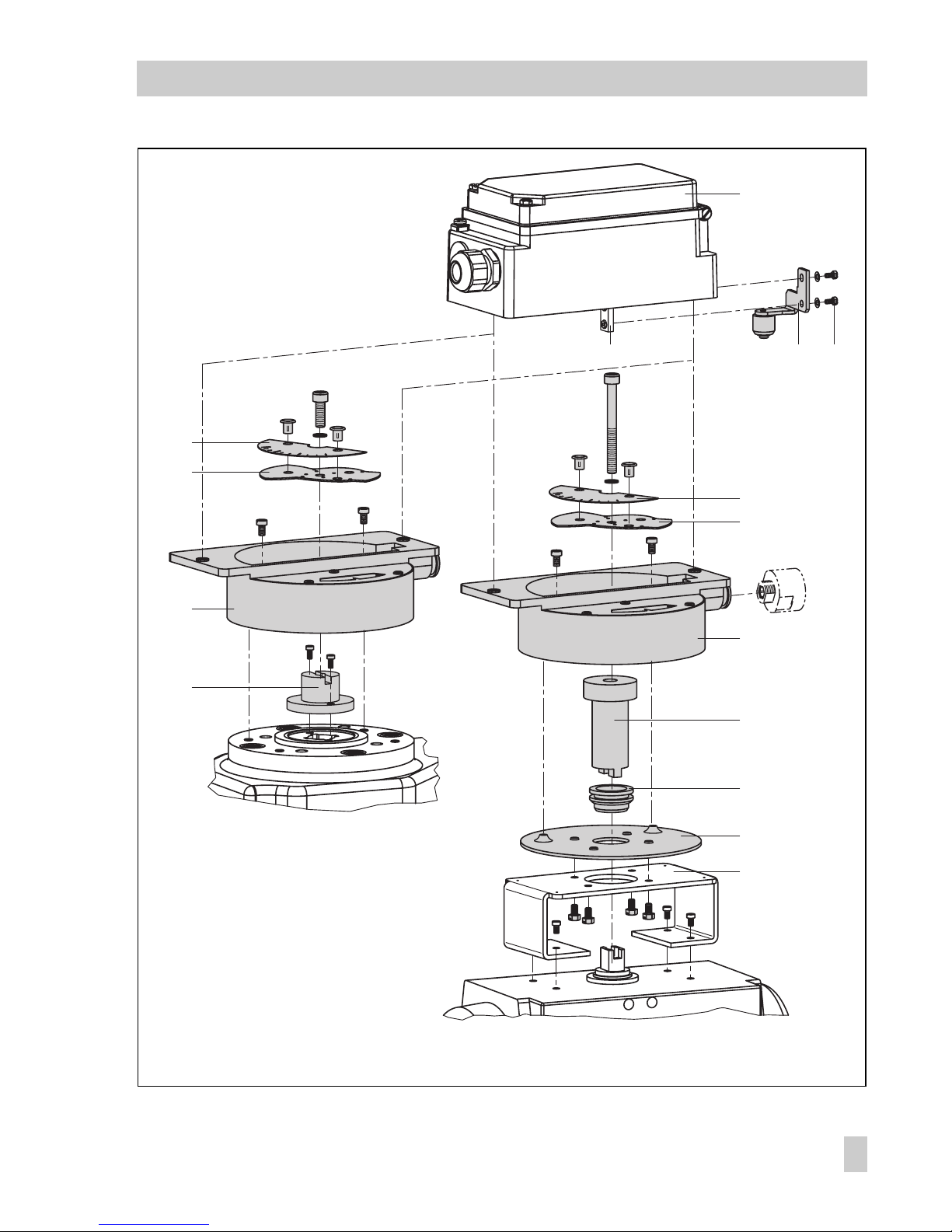
Vent p lu g o r
filter check valve
Fig. 5 ⋅Attachment to rotary actuators
33
3835
39
39
40
34
36
40
34
44
45
42
43
37
Attachment to
SAMSON Type 3278
Attachment acc. to
VDI/VDE 3845
33 Positioner
34 Intermediate piece
35 L ev er with ca m f ollowe r r oll
36 Adapter
37 Transmission lever
38 Screws
39 Scale
40 Cam disk
41 Actuator shaft
42 Plate
43 Bracket
44 Coupling
45 Seal
EB 8383-1 EN
19
Attachment to the control valve
Page 20

2.3.3 Aligning and mounting the
cam disk
In rotary actuators with spring-return mechanism, the actuator springs determine the
fail-safe position and the direction of rotation of the control valve.
With double-acting, springless rotary actuators, the direction of rotation depends on
both the actuator and valve version used.
The initial position is always based on a
closed valve!
Whether the control valve should open or
close when the reference variable increases
must be set in the software (direction of action increasing/increasing or increasing/decreasing).
1. Place the cam disk with scale on the
adapter (36) or coupling (34), and
fasten the screws loosely at first.
The cam disk has two cam sections. The
starting point of each section is marked by
a small hole.
Note!
When the valve is closed, the starting point
(hole) of the disk must be aligned so that the
pivot of the cam disk, the 0° position of the
scale and the arrow mark on the viewing
window are in one line.
The starting point for the closed valve position should never be below the 0° position!
In actuators with fail-safe position "valve
OPEN", the maximum signal pressure must
be applied to the actuator prior to aligning
the cam disk.
In springless actuators, the supply air must
be connected.
2. On aligning the cam disk, clip on the
double-sided scale disk so that the scale
matches the direction of rotation of the
control valve. Only then secure the cam
disk with the fastening screws.
Securing the aligned cam disk
If you want to additionally secure the cam
disk to prevent it from being turned, proceed as follows:
There are four holes arranged around the
center hole on the cam disk. Select a suitable hole from the four holes to secure the
cam disk.
Drill a hole in the adapter (36) or coupling
(44) through the hole chosen and insert a
2 mm dowel pin.
3. Attach the positioner to the intermediate
piece (34) so that the lever (35) touches
the cam disk with its feeler roll.
To do so, insert a 2.5 mm Allen key or
screwdriver from the front into the bore
hole located below an oblong hole in
the cover plate and bring the positioner
lever in the required position.
4. Screw positioner to the intermediate
piece.
20
EB 8383-1 EN
Attachment to the control valve
Page 21
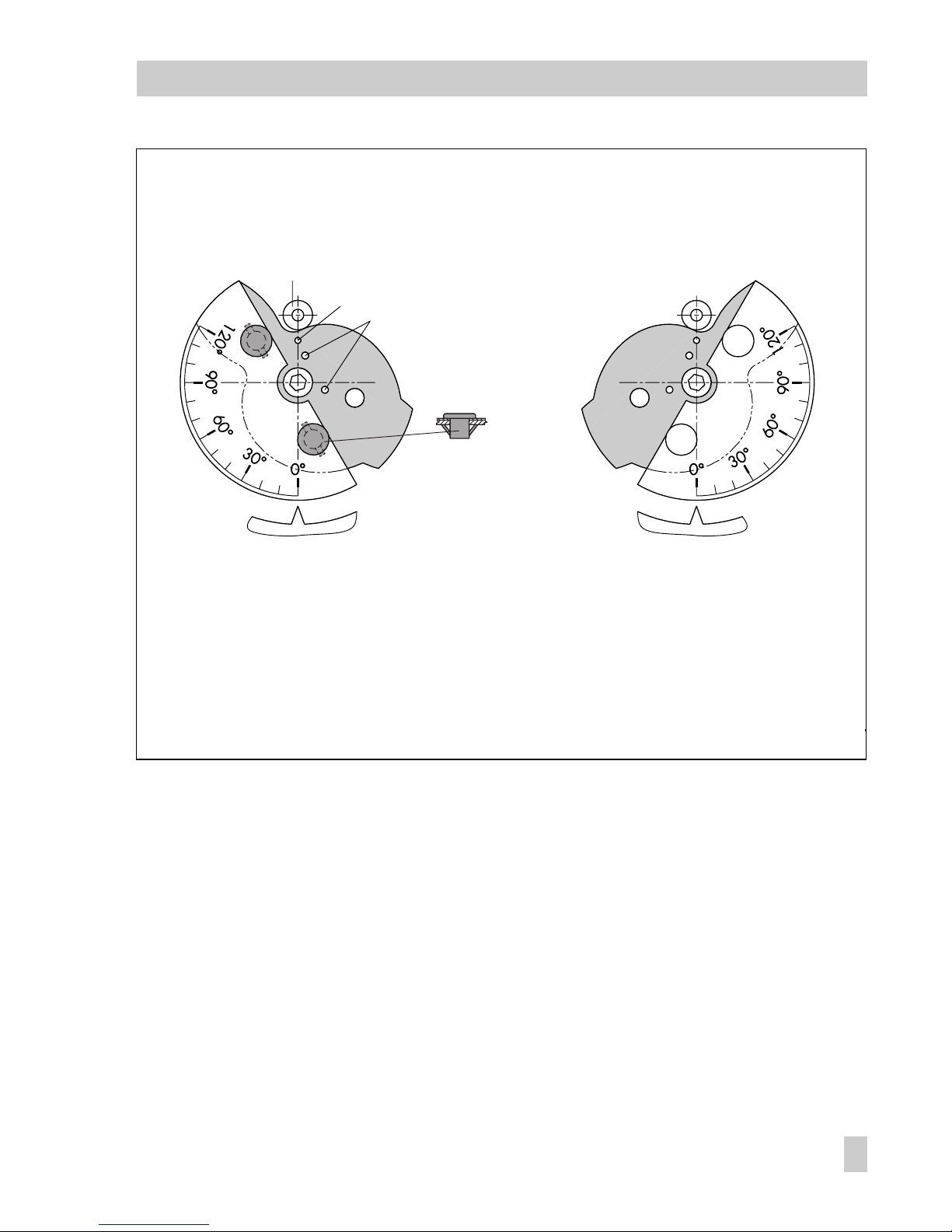
Fig. 6 ⋅Aligning the cam disk
Control valve opens
counterclockwise
Control valve opens
clockwise
Feeler roll
Starting point
Holes to secure the cam disk
View onto the actuator shaft from the positioner
Insert clip and then
press tongues outwards
EB 8383-1 EN
21
Attachment to the control valve
Page 22

2.3.4 Reversing amplifier for
double-acting actuators
For the use with double-acting actuators,
the positioner must be fitted with a reversing amplifier.
The reversing amplifier is listed as an accessory in the Table 6 on page 17.
The output signal pressure of the positioner
is supplied at the output A
1
of the reversing
amplifier. An opposing pressure, which
equals the required supply pressure when
added to the pressure at A
1,
is applied at
output A
2
. The rule A1 + A2 = Z applies.
Mounting
Note!
Prior to mounting the reversing amplifier,
remove the sealing plug (1.5). The rubber
seal (1.4) must be remain attached.
1. Thread the special nuts (1.3) from the
accessories of the reversing amplifier
into the threaded ports of the positioner.
2. Insert the gasket (1.2) into the recess of
the reversing amplifier and push both
the hollowed special screws (1.1) into
the connecting ports A1 and Z.
3. Place the reversing amplifier onto the
positioner and screw tight using both
the special screws (1.1).
4. Screw the supplied filter (1.6) using a
screwdriver (8 mm wide) into the connecting bore holes A1 and Z.
Signal pressure connections
A
1
: Output A1 leading to the signal pressure connection at the actuator which opens
the valve when the pressure increases
A
2
: Output A2 leading to the signal pressure connection at the actuator which closes
the valve when the pressure increases
Enter the actuator as "Double-acting
without spring-return mechanism" in the
user interface software under Start-up
→
Type of actuator.
2.4 Fail-safe action of the actuator
Note!
If the fail-safe action of the actuator is
changed subsequently by converting the actuator springs from "actuator stem extends"
to "actuator stem retracts", the mechanical
zero must be recalibrated and the positioner reinitialized.
22
EB 8383-1 EN
Reversing amplifier for double-acting actuators
Page 23
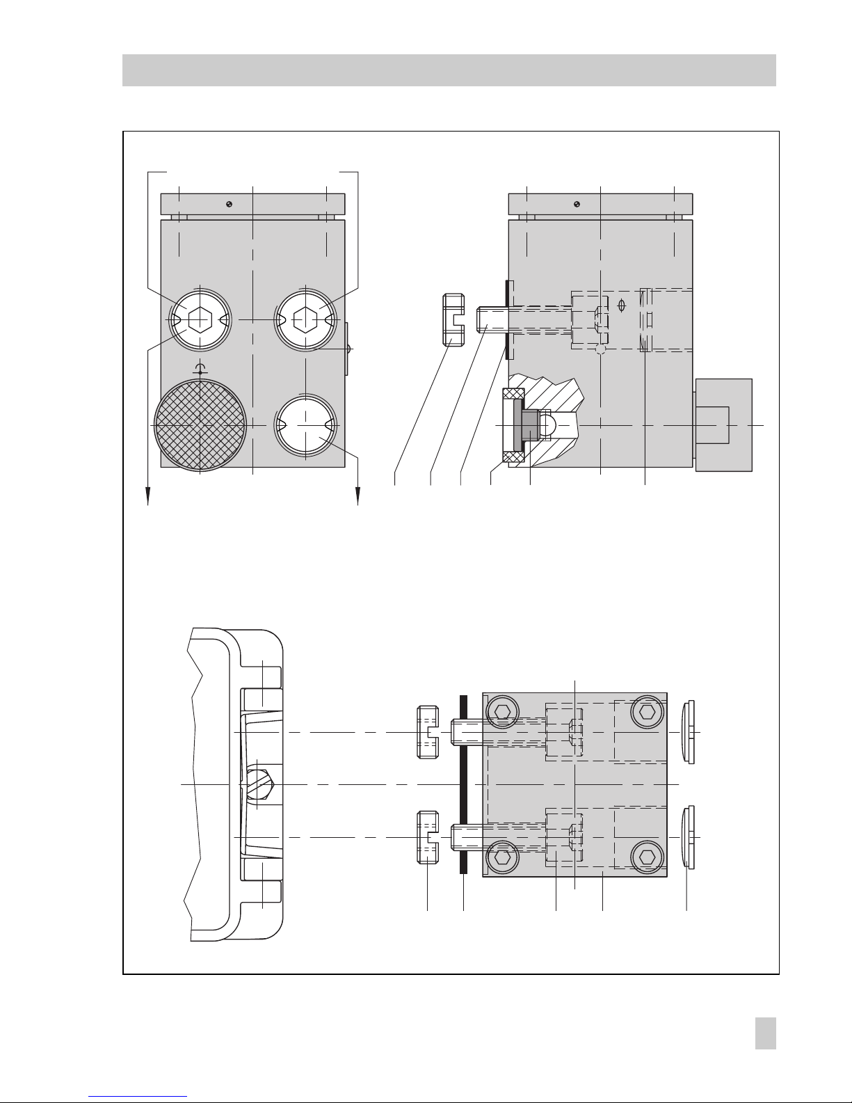
Fig. 7 ⋅Mounting a reversing amplifier
1.3 1.2 1.1 1
Output 38 Supply 9
A
1
1.5 1.6
Z
A
2
1.4
A
1
A
2
Output 38 Supply 9
1.3 1.21.1
1.6
Z
A
1
From the positioner
To the actuator
1 Reversing amplifier
1.1 Special screws
1.2 Gasket
1.3 Special nuts
1.4 Rubber seal
1.5 Plug
1.6 Filter
EB 8383-1 EN
23
Reversing amplifier for double-acting actuators
Page 24
3 Connections
3.1 Pneumatic connections
The air connections are either 1/4 NPT or
G 1/4 tapped holes. Customary fittings for
metal and copper pipes or plastic tubes can
be used.
Note!
The supply air must be dry and free from oil
and dust. Observe the maintenance instructions for upstream pressure reducing stations. Carefully purge all tubes before connecting them.
If the positoner is attached directly to Type
3277 Actuator, the connection for the signal pressure is fixed. For NAMUR attachment, the signal pressure can be applied to
either the top or bottom diaphragm chamber depending on the fail-safe position "actuator stem extends or retracts".
Exhaust air: The exhaust air connection of
the positioner is included in the mounting
parts. For direct attachment of the positioner, there is a vent plug on the plastic
cover of the actuator. For NAMUR attachment, this plug is on the adapter housing
and for attachment to rotary valves, it is on
the intermediate piece or reversing amplifier.
3.1.1 Pressure gauge
We recommend mounting pressure gauges
for supply air and signal pressure to monitor the positioner. The parts are listed as accessories in Tables 3, 4 and 6.
Fig. 8 ⋅Mounting the pressure gauge
2...3mm
Nut Throttle with filter
Order no. 0250-1090 1790-6121
24
EB 8383-1 EN
Connections
Page 25

3.1.2 Supply air pressure
The required supply air pressure depends
on the bench range and the operating direction (fail-safe position) of the actuator.
The bench range is mentioned on the nameplate as spring range or signal pressure
range.
Actuator stem extends:
Required supply air pressure =
Upper bench range value + 0.2 bar,
min. 1.4 bar.
Actuator stem retracts:
The required supply air pressure for tightclosing valves is calculated from the maximum signal pressure pst
max
pst
max
= F +
d
2
⋅ π ⋅ Δp
4 ⋅ A
[bar]
d = Seat diameter [cm]
Δ
p = Differential pressure across the valve [bar]
A = Actuator area [cm
2
]
F = Upper bench range value of the actuator [bar]
If there are no specifications, calculate as
follows:
Required supply air pressure = Upper
bench range value + 1 bar
3.2 Electrical connections
For electrical installation, you are required to observe the relevant electrotechnical regulations and the accident prevention regulations that
apply in the country of use. In Germany, these are the VDE regulations
and the accident prevention regulations of the employers liability insurance association.
The following standards apply for installation in hazardous areas:
EN 60079-14: 2003 (VDE 0165
Part 1)
"Electrical apparatus for ex-
plosive gas atmospheres"
and
EN 50281-1-2: 1999 (VDE 0165
Part 2)
"Electrical apparatus for use
in the presence of combustible
dust"
.
For the interconnection of intrinsically safe electrical equipment, the
permissible maximum values specified in the EC type examination certificate apply (U
i
or U0; Ii or I0; Pi or
P
0
; Ci or C0, and Li or L0).
For EEx nA equipment (non-sparking apparatus), the standard
EN 50021: 1999 specifies that connecting, interrupting, or switching
circuits while energized is only
allowed during installation, maintenance or repair work.
For EEx nL equipment (energylimited apparatus), the standard
EN 50021: 1999 allows this type of
equipment to be switched under normal operating conditions.
EB 8383-1 EN
25
Connections
Page 26

Caution!
The terminal assignment specified in
the certificate must be adhered to.
Reversing the assignment of the electrical terminals may cause the explosion protection to become ineffective!
Do not tamper with enameled
screws inside or on the housing.
Note on the selection of cables and
wires:
To install intrinsically safe circuits,
observe section 12 of the standard
EN 60079-14: 2003 (VDE 0165
Part 1).
To run multi-core cables or lines
with more than one intrinsically
safe circuit, section 12.2.2.7 of
this standard applies.
An additional cable gland can be
installed when connecting the device over two separate cables.
Cable entries left unused must be
sealed with blanking plugs.
Devices used at ambient temperatures down to 40 °C must have
metal cable entries.
The terminal assignment can be found in
Fig. 9 as well as on the labels on the cover
plate of the positioner case.
Cable entries
The cable entry with M20x1.5 cable gland,
7 to 12 mm clamping range.
There is a second M20x1.5 cable gland in
the housing that can be used for additional
connection, if required.
The screw terminals are designed for wire
cross-sections of 0.2 to 2.5 mm
2
. Tighten
by at least 0.5 Nm.
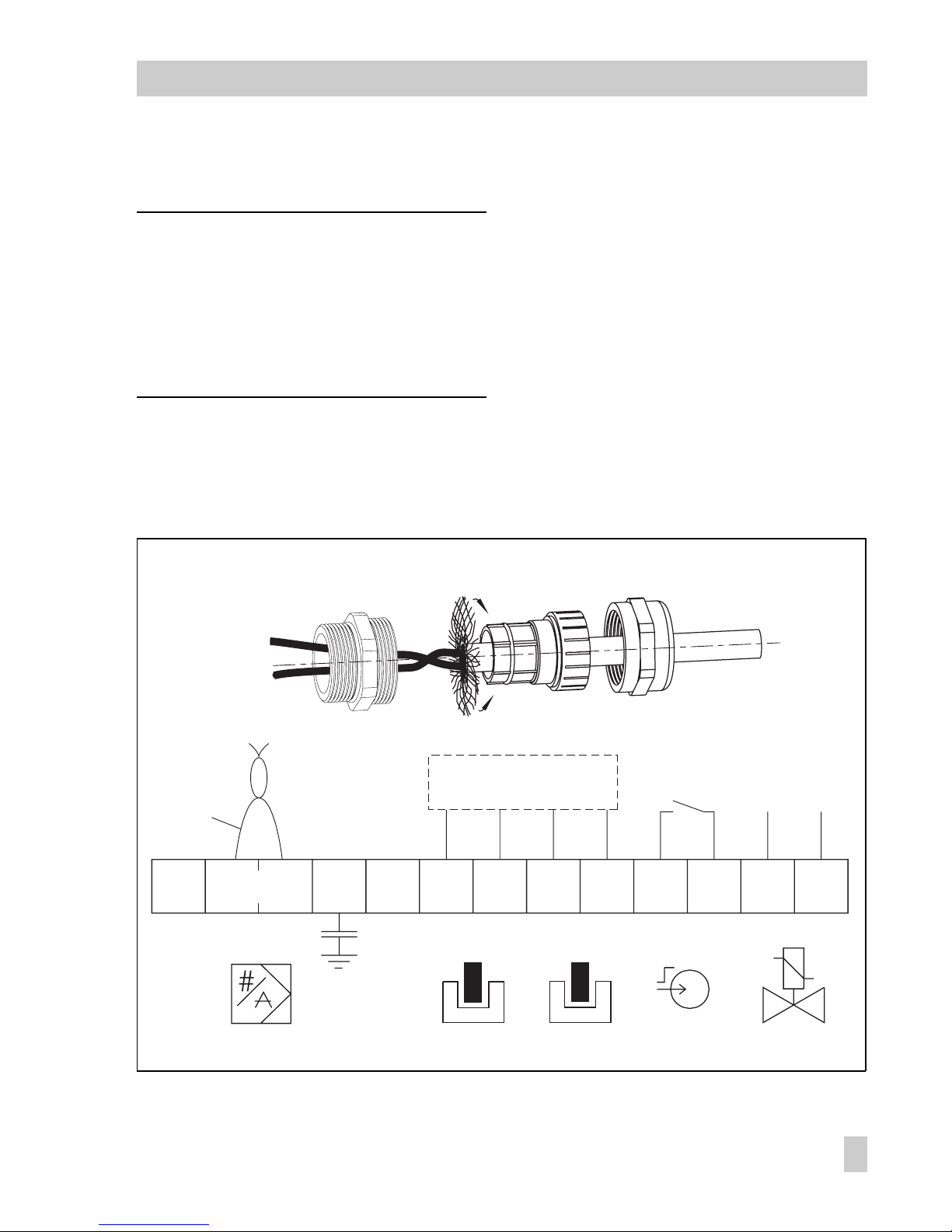
Bus line
The shielding of the Fieldbus connecting
cable is connected to the equipotential
bonding system on the process control system side. At the positioner side, the shielded
cable must be routed over the EMI-proof
brass cable gland (standard) of the positioner to the terminals. The shield which is
placed over the clamping insert is connected over a large area to the gland and
housing.
To connect the bus line, loosen the coupling nut and the clamping insert from the
positioner and remove the dust cap.
Slide the coupling nut and clamping insert over the connecting cable.
Insulate the end of the bus line to the required connecting length and cut the
wire shield off up to a length of approx.
13 mm. If necessary, cut off any cable
core filling as well.
Disentangle the braided shield and pull
it over the clamping insert.
Press the clamping insert into the connecting screw gland and screw tight the
coupling nut until the connecting cable is
clamped tight.
Route the two-wire bus line to the screw
terminals marked "IEC 1158-2",
whereby no polarity has to be observed.
In exceptional cases, when the plant may
not allow such a connection, feed the cable
shield through the cable gland and connect
it to be capacitive over the terminal "S".
However, make sure that a conducting connection cannot occur from the shield to the
cable gland or housing.
If the shielding is not placed on both sides,
we recommend installing an additional sup-
26
EB 8383-1 EN
Connections
Page 27
pressor kit (order no. 1400-9324). Separate installation instructions are included.
Note!
The connection of limit switches, binary
input and forced venting function requires
an additional cable gland that must replace
the cap fitted on the housing.
Accessories:
Cable gland M20 x 1.5, nickel-
plated brass, order no. 8808-0143
Limit switches
For operation of the limit switches, switching amplifiers have to be connected in the
output circuit. Their function is to control the
limit values of the control circuit according
to NAMUR, thus ensuring operational reliability of the positioner.
If the positioner is installed in hazardous
areas, the relevant regulations must be observed.
Binary input
A passive floating contact can be used at
the binary input. The positioner signals the
status over the bus protocol.
Fig. 9 ⋅Bus line connection and terminal assignment (terminal markings according to DIN 45140)
Brass screw fitting Shield Clamping insert Coupling nut
GW2 GW1
PE
S
NC
-52
+51
-42
+41 -86
+85
-82 +81
IEC 1158-2
FOUNDATION
TM
Fieldbus
Bus cable
Switching amplifier
acc. to EN 60 947-5-6
6 to 24 VDC
Limit switches Binary input Forced venting
EB 8383-1 EN
27
Connections
Page 28

Forced venting
For the positioners with forced venting function, a voltage between 6 and 24 V DC
must be connected to the terminals 81 and
82.
Note!
If there is no voltage connected or the voltage drops, the positioner vents the actuator
and does not respond to the reference variable.
28
EB 8383-1 EN
Connections
Page 29
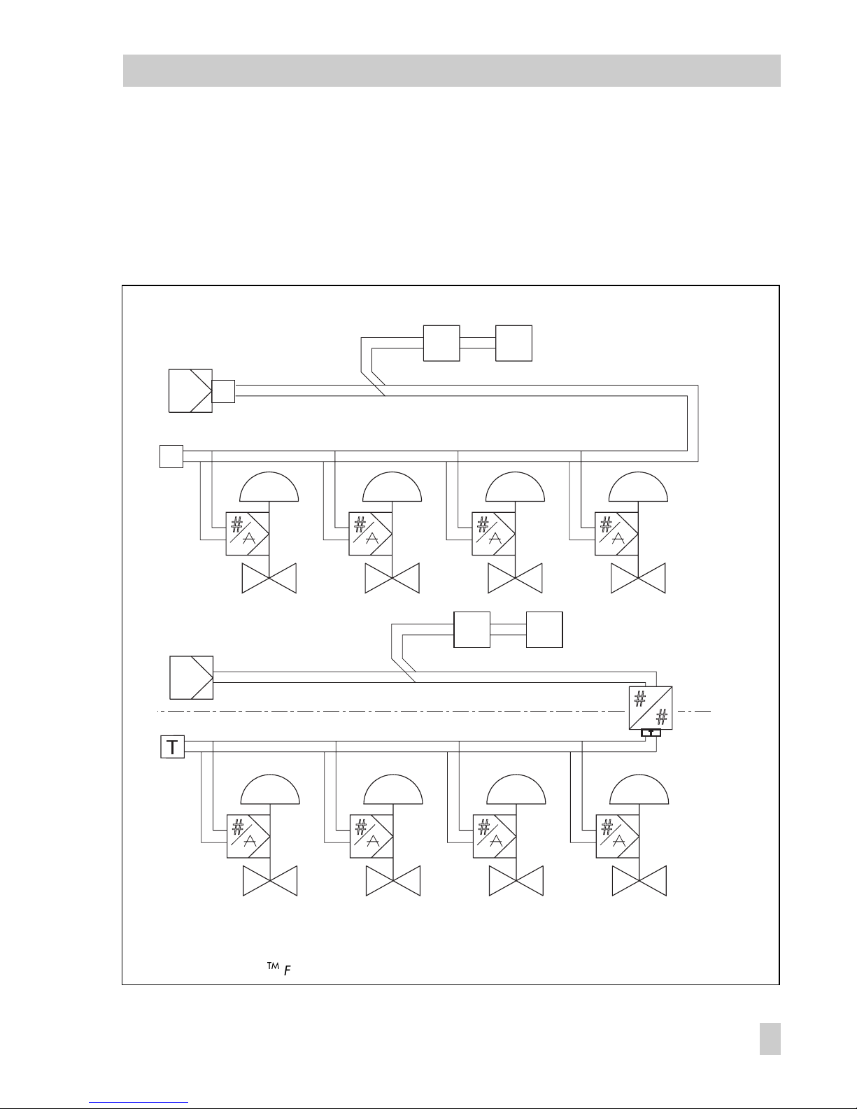
3.2.1 Establishing communication
Communication between positioner, programmable logic controller or automation
system or between PC and workstation and
positioner(s) is established in accordance
with IEC 61158-2.
If positioners are used in hazardous areas,
ex-barriers must be used.
A maximum of 32 control valves can be
operated in one segment. The number of positioners that can be connected is reduced
when they are used in hazardous areas.
Fig. 10 ⋅ FOUNDATIONTM Fieldbus connection, for non-hazardous areas (top) and for hazardous areas (bottom)
3787
3787
3787
3787
FOUNDATION
TM
Fieldbus IEC 61158-2
FOUNDATION
TM
Fieldbus IEC 61158-2
3787-1
3787-1
3787-1
3787-1
FOUNDATION
TM
Fieldbus IEC 61158-2
FOUNDATION
TM
Fieldbus
IEC 61158-2
Process
management
system
Process
management
system
Te rm in at i o n
Ex-fieldbus barriers
Termination
Hazardous area
Supply unit
Non-hazardous area
Supply unit
Termination
EB 8383-1 EN
29
Connections
Page 30

4Operation
Warning!
Before you take the control valve
into operation, carefully move the
control valve to its end position by
covering the hole (manual operation) on the cover plate (Fig. 11).
On doing so, check whether the
lever mechanism works properly.
If the maximum angle of rotation is
exceeded because the wrong lever
mechanism has been selected or incorrectly sized, the positioner may
be ruined.
4.1 LEDs
There are two LEDs located inside the cover
used to monitor the positioner during startup, operation and to indicate possible faults.
General meaning of LEDs:
Red
Device start-up or error,
no control operation possible
Green
No error detected, control operation
or fail-safe position
(e.g. if not initialized)
Red and green
Error detected,
control operation possible
See table below for detailed description.
Description LED
Device start-up:
Red on
No error detected:
Device connected to bus, cold start completed,
initialization required
Initialization or zero calibration running
Device is initialized, no valid set point
Device is initialized, valid set point, control operation
Green, generally
Green blinks slowly
Green blinks quickly
Green blinks 3x quickly + long interval
Green on
Error in the control loop:
Zero point error
Control loop fault
Red and green
Red and green blink slowly
Red and green blink quickly
Error leading to first initialization being cancelled
(Device does not go to standard operation)
Zero point error
Mechanics/pneumatics failure
Control loop fault
Red, generally
Red blinks slowly
Red on
Red blinks quickly
Device errors causing the control operation to be
left
Device has detected an internal fault Red blinks 3x quickly + long interval
30
EB 8383-1 EN
Operation
Page 31
4.2 Write protection and simulation switches
There are two microswitches inside the
hinged cover to activate the write protection
and enable simulation.
When the write protection switch is ON, the
configuration data of the positioner are
write-protected and cannot be overwritten.
The switch must be set to OFF before any
configuration data can be changed over the
communications.
The simulation switch enables the simulation
of the position value for Analog Output
Function Block using the Simulate parameter.
4.3 Activate/deactivate forced
venting function
For models with index .03 or higher:
1. Remove cover plate on the inside of the
positioner lid by unscrewing the four
screws.
2. Unscrew the central screw on the board
and push the board to one side.
3. Set switch to desired position:
1 ENABLED > Function activated
2 DISABLED > Function deactivated.
Dimensions
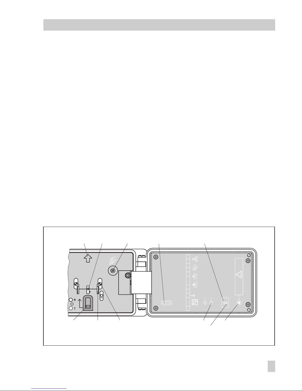
Fig. 11 ⋅View of the positioner cover open
GW1
GW2
3785
LED 1
LED 2
0
PE
IEC 1158-2
S
NC -52
+51
-42
+41
-86
+85
-82
+81
0N0FF
0FF
Caution!
Valve
actuates
Init/Zero
SERIAL
INTERFACE
FOUNDATION
Fieldbus
Simulation enable
Write protection
GW2 GW1
Arrow for mounting
position
Manual operation
Zero switch
Pointer
Adjustment screws for
limit switches
Key for initialization
and zero calibration
Metal tags
LED
Serial interface
Simulation switch
Write protection
switch
EB 8383-1 EN
31
Page 32

4.4 Default setting
All parameters are set to default values. See
chapter 7 on description of parameters.
Note!
Manual operation and activated final position functions can cause the actuator to
filled with the maximum supply pressure.
Should this lead to impermissible forces occurring, the supply pressure must be restricted by a reducing station.
4.4.1 Adjusting mechanical zero
Note!
Zero must be calibrated when the valve is
closed (with actuator stem extended in threeway valves).
Firmly push the zero switch, located on
the cover plate inside the positioner, in
the direction indicated by the arrow as
far as it will go once. The yellow pointer
will then be aligned with the white line.
For control valves which are open in their initial position, e.g. when the actuators failsafe position is "actuator stem retracts", the
positioner must be first supplied with air.
The manual operation function must then be
activated so that the supply pressure builds
up and moves the valve to the closed position. Then press the zero switch.
32
EB 8383-1 EN
Operation
Page 33

4.4.2 Initialization
After connecting the supply air and electrical connections to the bus cable, initialization must be started. During initialization,
the positioner adapts itself optimally to the
friction conditions and signal pressure requirements of the control valve.
Caution!
Initialization takes several minutes to
complete. During this time, the control valve moves. Therefore, never initialize while a process is running,
but only during the start-up phase
when the shut-off valves in the plant
section are closed. Alternatively,
remove the control valve with positioner from the plant and initialize
on a test bench.
Enter data on valve and actuator under
"Start-up" in the operating software.
Set "Type of initialization" to "Rated
range", select "Maximum range" only
for three-way valves.
Start initialization.
A successful initialization is indicated in the
operating software and over the LEDs (see
chapter 4.1).
Carry out the configuration suitable for
the valve type.
The following setting is recommended:
Fail-safe position "Actuator stem extends":
Direction of action: increasing/increasing (>>), the globe valve opens with increasing reference variable
Final position at a reference variable
less than 1% (tight closing),
Final position at a reference variable
larger than 125 % (function deactivated).
Fail-safe position "Actuator stem retracts":
Direction of action: increasing/decreasing (<>), the globe valve closes with increasing reference variable
Final position at a reference variable
less than −2.5% (function deactivated),
Final position at a reference variable
larger than 99 % (tight closing).
Set delay time to 30 s at the minimum.
Enter tag reference.
If necessary, other configuration, e.g.
special characteristics for rotary valves.
If there is
no communication
set up on the
valve, initialization directly at the valve is
also possible.
Connect positioners that are not
mounted on a valve to a power supply
and initialize the positioner as described
in chapter 4.4.2.
If communication is not possible, the default setting must be used.
Mount positioner and set the mechanical
zero as described in chapter 4.4.1.
Start initialization by pressing the
Init/Zero
key on the positioner case cover using a
suitable tool.
The initialization is completed when the positioner takes on the position predetermined
by the reference variable.
EB 8383-1 EN
33
Operation
Page 34

Note!
After the positioner has been initialized successfully for the first time, pressing the
Init/Zero
key subsequently only starts a
zero calibration.
A new initialization routine can only be
started after this when the communication is
connected.
A completed initialization can be cancelled
via the communication with the command
"Reset to default values". After this, the
Init/Zero key can be pressed to start a complete initialization.
Electric zero calibration
If, during the valves operation, the mechanical zero has shifted, an electric zero calibration can be carried out. To do this, press
the Init/Zero key located on the inside of
the cover (Fig. 11).
Caution!
The control valve moves to its final
position.
Firmly press the zero switch, located on
the cover plate of the positioner, in the
direction indicated by the arrow as far
as it will go once. The yellow pointer will
then be aligned with the white line.
Press the key again to start the electric
calibration.
After the key is pressed twice, it is locked
for approximately one minute!
The electric calibration has been completed
when the positioner takes on the position
predetermined by the reference variable.
34
EB 8383-1 EN
Operation
Page 35

4.5 Operation via TROVIS-VIEW
In addition to using the fieldbus configuration or operating system via fieldbus communication, the positioner can also be operated with SAMSONs TROVIS-VIEW user interface via the serial port integrated in the
device.
You can configure all the parameters using
the device module intended for the TROVISVIEW software.
For connection of the positioner to the serial
port of the PC, you will need an adapter
(order no. 1400-7700).
You can either connect the power supply to
the device using a fieldbus segment, or by
connecting a voltage source (9 to 32 V) to
the bus terminals on the device.
When the device is connected to a Foundation Fieldbus bus segment, you can simultaneously operate TROVIS-VIEW and the
fieldbus system without any restrictions.
4.5.1 Initialization
When you initialize the device via the
fieldbus system or TROVIS-VIEW, the initialization routine is started over the parameter
SELF_CALIB_CMD.
You can select an initialization routine
based on either the nominal range or maximum range by setting the parameter
INIT_METHOD accordingly.
During initialization based on nominal
range, the following parameters must be set:
VALVE_TYPE
Option: Rotary or linear actuator
MOUNTING_POSITION
Positioner alignment to actuator (for linear actuator).
ATTACHMENT
Defines the attachment of the positioner
(Select: Namur/integrated).
RATED_TRAVEL
Rated travel or nominal angle of the
valve
ACTUATOR_VERSION
Determines whether the actuator is single
acting or double acting.
Options for linear actuator with NAMUR attachment:
TRANSM_LENGTH
Specifies the length of the lever
TRANSM_PIN_POS
Specifies the position of the pin on the
lever.
Options for linear actuator with integrated
attachment:
TRANSM_CODE
Determines the size of the travel pick-off
for integrated attachment.
Options for rotary actuator:
TRANSM_CODE
Determines the cam disk used.
During initialization, the following parameters are determined:
ACT_FAIL_ACTION
Fail-safe action of the actuator when the
supply air fails.
ACT_STROKE_TIME_DEC
Minimum transit time to CLOSED position
ACT_STROKE_TIME_INC
Minimum transit time to OPEN position
EB 8383-1 EN
35
Operation
Page 36

MAX_HUB
Maximum travel/angle of rotation in percent of the rated travel/nominal angle.
The integrated LEDs and the parameters
SELF_CALIB_STATUS
SELF_CALIB_WARNUNG
indicate if the initialization has been successfully completed or whether errors have
occurred.
4.5.2 Testing the control valve
Upon successful initialization, you can easily test the control valve using TROVIS-VIEW
software. This function allows you to run the
valve for test purposes without the use of a
complex fieldbus system and without requiring knowledge about the function blocks
and their configuration.
Proceed as follows:
1. Set the Transducer Block to
"Local override" mode:
In the menu "Positioner-> Operating
mode TRD" under "Required operating
mode" select "Local override (LO)".
Deactivate the option "Fail safe position
(O/S)".
2. Defining a positioning value:
In the menu "Positioner-> Process
data", you can select a positioning
value for the valve over "Positioning
value TRD" (FINAL_VALUE).
Note that the status of the positioning
value must be set to "Good".
The position feedback can be retrieved
via "Current valve position"
(FINAL_POSITION_VALUE).
3. Set the Transducer Block to the "Auto"
mode.
In the menu "Positioner-> Operating
mode TRD" under "Required operating
mode" select "Automatic (AUTO)".
Deactivate the option "Local override
(LO)".
4.6 Setting the inductive limit swit-
ches
The positioner version with inductive limit
switches has two adjustable tags that are
mounted on the shaft of the positioner lever
and operate the associated proximity switches.
For operation of the inductive limit switches,
the corresponding switching amplifiers have
to be connected to the output. If the tag is in
the inductive field of the switch, the switch
assumes a high resistance. If the tag is out
of the field, the switch assumes a low resistance.
Normally, the limit switches are adjusted
such that they will provide a signal in both
end positions of the valve. These switches,
however, can also be adjusted to indicate
intermediate valve positions.
The desired switching function, i.e. whether
the output relay shall be picked up or released when the tag has entered the field,
has to be selected, if necessary, at the
switching amplifier.
36
EB 8383-1 EN
Operation
Page 37

Adjusting the switching point:
The limit switches are marked GW1 and
GW2 on the inside of the case cover. Yellow tags and the associated adjustment
screws (Fig. 11) are located below these
markings.
Each switching position can optionally be indicated when the tag has entered the field, or
when it has left the field.
Move the valve to the switching position
and adjust the tag of the required limit
switch GW1 or GW2 by turning the related adjustment screw until the switching
point is reached. This is indicated by the
LED at the switching amplifier.
In so doing, one edge of the yellow tag will
be in alignment with the white, horizontal
line on the case cover. This indicates the
side from which the tag enters the inductive
field of the proximity switch.
To ensure safe switching under any ambient
conditions, the switching point should be adjusted to a value of approx. 5% before the
mechanical stop (OPEN - CLOSED).
5 Maintenance
The positioner is maintenance-free.
Pneumatic connection 9/Supply contains a
sieve with a mesh size of 100 μm. If required, the sieve can be unscrewed and
cleaned.
Please also observe the maintenance instructions for upstream pressure reducing
stations for supply air, if applicable.
6 Servicing explosion-protected
versions
If a part of the positioner on which the explosion protection is based needs to be serviced, the positioner must not be put back
into operation until an expert has inspected
the device according to explosion protection requirements, has issued a certificate
stating this or given the device a mark of
conformity.
Inspection by an expert is not required if the
manufacturer performs a routine test on the
device prior to putting it back into operation. The passing of the routine test must
be documented by attaching a mark of conformity to the device.
Explosion-protected components may only
be replaced by original, checked components from the manufacturer.
Devices that have already been used outside of hazardous areas and are intended
for use in hazardous areas in future must
comply with the safety demands placed on
repaired devices. Prior to operation, they
must be tested according to the specifications stipulated for "Repairing explosionprotected devices".
EB 8383-1 EN
37
Maintenance
Page 38

7 Parameter description
7.1 General
The section is based on:
Fieldbus Foundation Specification "Function Block Application Process Part 1 to 3"
Revision 1.4.
Fieldbus Foundation Specification "Transducer Block Application Process Part 1 to 2"
Revision PS 3.0.
7.2 Device Description (DD)
The following Device Description files are required for integrating the device described into
host systems:
Device Description: < 0201.ffo >, < 0201.sym >
Capabilities File: < 020101.cff >
You can order these Device Description files on disk (3 1/2") from SAMSON under the pro-
duct number 1400-7705 or you can download them from the Internet at
www.samson.de
or
www.fieldbus.org
.
Note:
The file < Positioner 3787_Rev2.fhx > is required for integration into the System DeltaV from Fisher-Rosemount, instead of the capabilities file from Fieldbus Foundation.
This file can be provided by SAMSON.
7.3 Notes on the parameters
All times specified in the Resource Block are in 1/32 ms units in accordance with the
Fieldbus specification Version 1.4.
In the Device Description Library supplied by the Fieldbus Foundation on which the Device
Description of the Type 3787 is based, these parameters are incorrectly shown with the ms
unit. The numerical values supplied by the device should, however, always be interpreted as
units of 1/32 ms.
Due to the same reason, the IO_OPTS parameter in the AO Block displays "Fault state to
value" as "Fault state type".
Several parameters can only be altered in certain modes (see "Access" in Parameter description).
Therefore, it is important that the Target Mode is set and not the Actual Mode.
38
EB 8383-1 EN
Parameter description
Page 39

7.3.1 Legends assigned to the parameters
r= Read
w= Write
Index = Relative index of the parameter in each block
O/S = Out of Service
MAN = Manual
AUTO = Automatic
CAS = Cascade
RCAS = Remote Cascade
ROUT = Remote Output
S = Static parameter
N = Non-volatile parameter
D = Dynamic parameter
7.3.2 Notes on parameter storage classes S, N and D
Static and non-volatile parameters are stored in the positioners EEPROM.
If such parameters are changed over acyclic FOUNDATION Fieldbus communication, the changes are saved in the EEPROM.
The number of write accesses granted to the EEPROM is limited due to technical restrictions.
Writing of transducer block parameters is limited to 10,000 accesses. For all other
blocks, the limit is 1 million.
These access limits must be observed. If they are exceeded, integrity of the stored
data and thus the function of the positioner can no longer be guaranteed due to data
being overwritten.
Make sure these parameters are not constantly overwritten by acyclic FOUNDATION
Fieldbus transfers.
When transferring data to the positioner using cyclic, scheduled FOUNDATION
Fieldbus publishing (Publisher/Subscriber), these data are not saved in the EEPROM.
EB 8383-1 EN
39
Parameter description
Page 40

7.4 Block structure
FOUNDATION Fieldbus assigns all functions and data of a device to three different block
types. Each block type has a different area of application.
A FOUNDATION Fieldbus device has the following block types:
One Resource Block
The Resource Block contains all the hardware specific characteristics.
One or more Transducer Blocks
The Transducer Block contains all the data and device-specific parameters to link the
device to the process data (sensor or actuator).
One or more Function Blocks
Function Blocks provide generally useable automation functions.
There are various different types of Function Block, e.g. Analog Input Function Block,
Analog Output Function Block, PID Function Block and other input, output and processing
blocks.
Each of these Function Blocks can be used for processing various application functions in
the entire automation system.
Various tasks can be solved depending on how individual blocks are arranged and connected.
40
EB 8383-1 EN
Parameter description
Page 41

The SAMSON Type 3787 Foundation Fieldbus Positioner contains the following blocks:
One Resource Block.
One Standard Advanced Positioner Valve Transducer Block.
Two Function Blocks:
one Analog Output Function Block,
one PID Function Block.
Fig. 12 ⋅Block structure
RCAS_IN
CAS_IN
OUT
MODE_BLK
(manual)
Analog Output Block
PV
Final Value
>
_
&
1
>
_
1
e
p
e
p
&
&
PWM
PWM
FINAL POSITION VALUE
Transducer Block
Pneumatik
Block
MODE_BLK
SP
>
_
OUT
FINAL_VALUE_CUTOFF_LO
FINAL_VALUE_CUTOFF_HI
READBACK
SP
Set point
ramps
Sp_RATE_DN
Sp_RATE_UP
PV, XD
scaling
XD_SCALE
PV_SCALE
high
To o u ts i de
RATED_TRAVEL
Fail-safe action
ACT_FAIL_ACTION
PD controller
SERVO_GAIN_1
SERVO_GAIN_2
SERVO_RATE
Forced venting
Fail-safe position
Hardware, firmware error
Characteristic
selection
Charact
XD, PV scaling
XD_SCALE, PV_SCALE
Set point
limits
SP_HI_LIM
SP_LO_LI
Output
options
IO_OPTS
low
1: active 0: inactive
Supply air
Filter
EB 8383-1 EN
41
Parameter description
Page 42

7.4.1 Resource Block
The Resource Block contains all the data that clearly identifies the device. It is, so to speak,
the electronic nameplate of the device.
The Resource Blocks parameters include, for example, device type, device name, manufacturer ID, serial number as well as parameters which affect the behavior of all other Blocks in
the device.
Parameters of the Resource Block
Storage class:
ACK_OPTION
S
Index: 38
Access: r, w
Options:
Default:
This parameter allows you to choose whether an alarm associated with this block
should be automatically acknowledged, i.e. without any influence from fieldbus host
system.
Undefined No option
DISC ALM Write protection has been changed
BLOCK ALM Block alarm
Undefined
Note : T he alar m i s s ent to th e f ieldbu s host sy st em, but it is not ack no wl edged by it .
ALARM_SUM
S
Index: 37
Access: r, w
Display:
Shows current status of process alarms in the Resource Block.
DISC ALM Write protection has been changed
BLOCK ALM Block alarm
Note:
Additionally, the process alarms can be cleared in this parameter group.
ALERT_KEY
S
Index: 4
Access: r; w
Input:
Default:
The identification number of the plant unit. This information may be used in the
fiel dbus ho st sy stem fo r s or ti ng alar ms an d event s.
1...255
0
Note: The value 0 (default) is not a tolerated value and is therefore rejected with an
error message when writing to the device.
BLOCK_ALARM
D
Index: 36
Access: r; w
Sho ws th e curre nt block s ta tu s with i nf or mation ab ou t exist in g c onfigu ra tion,
hardware or system errors.
Note: Additionally, the active block alarm can be manually acknowledged in this
parameter group.
BLOCK_ERR
D
Index: 6
Access: r
Display:
Sho ws th e activ e b lo ck erro r.
SIMU LATE A CTIVE Sim u latio n possib le, Simulation En able se t.
OUT OF SE RVICE T h e b lock model is O/S .
LOST STATIC DATA D ata loss in E EPROM
DEVICE NEEDS MAINTENANCE SOON
(Zero error, control loop disturbed or total valve travel.
exce ed ed). Th is alert tr ig gers a b lo ck alar m ( BL OCK_ALM ) o f
the ResourceBlock.
42
EB 8383-1 EN
Parameter description
Page 43

CLR_FSTATE
D
Index: 30
Access: r, w
Writing a Clear to this parameter will clear the fault state of the Analog Output
Function Block.
CONFIRM_TIME
S
Index: 33
Access: r, w
Default:
Defa ult of co nf ir mation t im e f or eve nt re port.
If the device does not receive any confirmation within this time, the event report is sent
again.
640000 1/32 ms
CYCLE_TIME
S
Index: 20
Access: r, w
Options:
Default:
Block execution methods predetermined by fieldbus host system.
SCHEDULED
COMPLETION OF BLOCK EXECUTION
SCHEDULED
Note: The execution method is selected directly in the fieldbus host system.
CYCLE_TYPE
S
Ind ex: 1 9
Access: r
Display:
Shows the block execution methods supported by the device.
SCHEDULED
COMPLETION OF BLOCK EXECUTION
DD_RESOURCE
S
Index: 9
Access: r
Shows the string for the Device Description in the device.
Not e: If there is not Devic e Description in th e dev ice, "null" ap pear s in the di spla y.
DD_REV
S
Index: 13
Access: r
Shows revision number of Device Description.
DESCRIPTOR
S
Index: 46
Access: r, w
Description,
freely available space for entering text to describe the application, stored in the field
device.
DEV_REV
S
Index: 12
Access: r
Shows the revision number of the device.
DEV_TYPE
S
Index: 11
Access: r
Display:
Shows the device type in decimal number format.
1 for Type 3787
DEVICE_ CERTIFICATION
N
Index: 45
Access: r
Type of protection,
indicates whether Ex approvals for this field device are available.
DEVICE_MESSAGE
N
Index: 47
Access: r, w
Message,
freely available space for entering text stored in the field device.
DEVICE_ PRODUCT_NUM
N
Index: 48
Access: r
Product number of the positioner.
EB 8383-1 EN
43
Parameter description
Page 44

DEVICE_ SER_NUM
N
Index: 44
Access: r
Serial number of the device,
allows together with MANUFAC_ID and DEV_TYPE the clear identification of the field
device.
FAULT_STATE
N
Index: 28
Access: r
Shows current status of the fault state of the Analog Output Function Block.
FEATURES
S
Index: 17
Access: r
Shows additional functions supported by the device, see FEATURES_SEL.
FEATURES_SEL
S
Index: 18
Access: r, w
Options:
Used to select the additional functions supported by the device.
REPORTS The fieldbus host system must acknowledge receipt of the event
report.
HARD W LOCK Hardware write protection switch is interpreted.
FAULTSTATE Fault state can be initiated
(see SET_FSTATE / C L R _ F STAT E)
OUT READBACK Current valve position is issued in PV of the Analog Output Function
Block (otherwise SP).
FREE_TIME
D
Index: 25
Access: r
Shows the free system time (in percent) which is available to process additional
function blocks.
Note: This parameter is not supported as the function blocks of the Type 3787 are
configured invariably.
FREE_SPACE
D
Index: 24
Access: r, w
Shows the free memory (in percent) which is available to process additional function
blocks.
Note: This parameter is not supported as the function blocks of the Type 3787 are
configured invariably.
GRANT_DENY
D
Index: 14
Access: r
Grant or deny access of host computer to the field device.
Note: This parameter is not interpreted by the Type 3787.
HARD_TYPES
S
Index: 15
Access: r, w
Display:
Sho ws th e t ypes of ou tp ut signa l f or the Ana lo g O utput F un ct ion Blo ck .
SCALAR OUTPUT scalable analog output variable
HW_REVISION
S
Index: 43
Access: r
Har dw are edi ti on of elec tr onics / me ch anics.
ITK_VER
S
Index: 41
Version number of the interoperability test system used to certify this device.
LIM_NOTIFY
S
Index: 32
Access: r, w
Option:
Default:
Maximum number of unacknowledged event reports allowed.
0 to 8
8
44
EB 8383-1 EN
Parameter description
Page 45

MANUFAC_ID
S
Index: 10
Access: r
Display:
Shows the manufacturer identification number.
0 x 00E099 = SAMSON AG
MAX_NOTIFY
S
Index: 31
Access:
r
Display
Shows the maximum number of unacknowledged event reports possible.
8
MEMORY_SIZE
S
Index: 22
Access: r
Shows available configuration memory in kilobyte.
Note: This parameter is not supported as the function blocks of the Type 3787 are
configured as permanent.
MIN_CYCLE_T
S
Index: 21
Access:
r
Display:
Shows time duration of the shortest cycle interval of which the device is capable
(ex ecution time of the A O Function Block 50 ms).
1600 1/32 ms
MODE_BLK
N
Index: 5
Access:
r, w
Display:
Shows the actual, target, permitted and normal modes of the Resource Block.
AUTO
O/S
The Resource Block supports the following modes:
AUTO
In this mode, the execution of the function blocks is (AO and PID Function
Blocks) granted.
O/S
In this operating mode, the execution of the function blocks is (AO and PID
Function Blocks) is stopped.
These blocks then go into O/S mode.
NV_CYCLE_T
S
Index: 23
Access:
r
Shows the minimum time interval for copying device data to non-volatile memory.
Note: Non-volatile data are saved directly after being transferred in the Type 3787.
RESTART
D
Index: 16
Access:
r, w
Option:
Allows a manual restart to be initiated. Several degrees of restart are possible.
RUN Standard operation
RESOURCE (is not supported)
DEFAULTS Device data and connection of the function blocks are reset
to the values determined in the specification.
PROCESSOR Reset of the device, reboost of the processor.
EB 8383-1 EN
45
Parameter description
Page 46

RS_STATE
D
Index: 7
Access:
r
Display:
Shows the actual operating state of the Resource Block.
ONLINE Standard operation, the block is in the operating mode AUTO.
STANDBY The Resource Block is in the operating mode O/S.
ONLINE LINKING The configured links among the function blocks are still not
set up.
SET_FSTATE D
Index: 29
Access:
r, w
Allo ws the Fau lt St ate cond ition o f t he An alog Out pu t Funct io n B lock to b e m anuall y
initiated by selecting Set.
SHED_RCAS
S
Index: 26
Access:
r, w
Det ermines m onito ring time for checking t he li nk be tween the fiel dbus host system and
the PID Block in the RCAS mode.
Afte r t he monito ri ng time ha s elaps ed , the PI D B lo ck chan ge s from R CA S m od e t o t he
mode selected in SHED_OPT.
SHED_ROUT
S
Index: 27
Access:
r, w
Default:
Det ermines m onito ring time for checking t he li nk be tween the fiel dbus host system and
the PID Block in the ROUT mode.
Afte r t he monito ri ng time ha s elaps ed , the PI D B lo ck chan ge s from R OU T m od e t o t he
mode selected in SHED_OPT.
640000 1/32 ms
SW_REVISION
N
Index: 42
Access: r
Firmware version (communication/positioner)
STRATEGY
S
Index: 3
Access: r, w
Default:
The s tr ategy f ie ld can b e u sed to i de nt ify gro up ing of bl oc ks to al lo w a faster an alysis
of the blocks . Ente r the s ame number in the S TRATEGY paramet er of each blo ck t o
group blocks.
0
Note: This data is not checked or processed by the Resource Block.
ST_REV
N
Index: 1
Access: r
Shows the revision level of the static data.
Note : T he revi si on leve l w ill be in cremen te d each t im e a static pa ramete r i n the bl oc k i s
changed.
TAG_DESC
S
Index: 2
Access: r, w
Default:
For e nt ering a us er-sp ec fi c text o f m ax . 3 2 c harac te rs to cle ar ly iden tify and assign th e
block.
No text
TEST_RW
D
Index: 8
Access: r, w
Note:
This parameter is only required for conformity tests and has no meaning in standard
operation.
TEXT_INPUT_1
N
Index: 50
Access: r, w
Freely available space for entering text
TEXT_INPUT_2
N
Index: 51
Access: r, w
Freely available space for entering text
46
EB 8383-1 EN
Parameter description
Page 47

TEXT_INPUT_3
N
Index: 52
Access: r, w
Freely available space for entering text.
UPDATE_EVT
D
Index: 35
Access: r
This alert is generated by any change to the static data, including date and time.
WRITE_ALM
D
Index: 40
Access: r, w
Shows status of the write protection alarm.
Note:
Thi s a ler t is gen er ated i f t he write l oc k param et er is cle ared.
In addition, the active write protection alarm can be manually acknowledged in this
parameter group.
WRITE_LOCK
S
Index: 34
Access: r, w
Option:
For hardware write protection: Shows status of the write protection
For software write protection: Enable/clear write protection
LOCKED
NOT LOCKED
WRITE_PRI
S
Index: 39
Access: r, w
Input:
Default:
Determines the handling when a write protection alarm is generated (parameter
"WRITE_ALM").
0 T he write protection alarm is not inte rpreted
1 T he fieldbus ho st system is no t aler ted wh en a write pro tecti on alarm
is generated
2 Reserved for block alarms
3...7 The write protection alarm is issued with the corresponding priority
(3 = low priority, 7 = hi gh pr iority) to notif y the user.
8...15 The write protection alarm is issued with the corresponding priority
(8 = low priority, 15 = high priority) as a critical alarm.
0
WRITE_PROTECT_SWITCH
D
Index: 49
Access: r
Position of the write protection switch in the device
0 = Not write-protected
1 = Write-protected
EB 8383-1 EN
47
Parameter description
Page 48

7.4.2 Transducer Block
The Transducer Block enables the input and output variables of a function block to be influenced. In this way, measured and control data can be calibrated, characteristics can be
linearized or physical variables can be converted with the aid of process data.
Parameters of the Transducer Blocks include, for example, information about the actuator
type, attachment, engineering units, start-up, diagnostics as well as device-specific data.
The Standard Advanced Positioner Valve Transducer Block
receives a correction value from
an upstream connected Analog Output Function Block. This value is used to position a control valve. The Block contains parameters for adaptation to actuator and valve, for start-up
and for control valve diagnosis.
Parameters of the Standard Advanced Positioner Valve Transducer Block
This Block contains parameters for descriptions about actuator and valve, to which the positioner is attached. The parameters of this block are used to adapt the positioner to the valve
and for start-up and diagnosis of the control valve.
Fig. 13 ⋅Transducer Block
FINAL_VALUE_CUTOFF_LO
>
_
&
1
>
_
1
e
p
e
p
&
&
PWM
PWM
Pneumatik
Block
>
_
FINAL_VALUE_CUTOFF_HI
FINAL POSITION VALUE
Characteristic
selection
CHARACT
Fail-safe action
ACT_FAIL_ACTION
RATED_TRAVEL
Supply air
Forced venting assembly
MODE_BLOCK O/S
Hardware, Firmware error
in Type 3787
To
AO Block READBACK
FINAL VALUE from AO Block OUT
high
low
Filter
To o u t si d e
1: active 0: inactive
PD controller
SERVO_Gain_1
SERVO_Gain_2
SERVO_RATE
48
EB 8383-1 EN
Parameter description
Page 49

Note:
When initialization based on maximum range (default) is selected, the positioner can be
started up directly after being attached to the control valve via the SELF_CALIB_CMD parameter.
The results of the initialization are saved in SELF_CALIB_STATUS. When this type of initialization is used, other parameters in this block generally do not require any adaptation.
ACT_FAIL_ACTION
S
Index: 21
Access: r
Display:
Fail-safe position of the actuator when the auxiliary power fails. It is determined
automatically during initialization.
UNINITIALIZED Not initialized, undefined
SELF-CLOSING Closing (in direction 0 % position)
SELF-OPENING Opening (in direction 100 % position)
INDETERMINATE None
ACT_MAN_ID
S
Index: 22
Access:
r, w
Manufacturer of actuator
Clearly identifies the manufacturer of the actuator associated with the positioner.
ACT_MODEL_NUM
S
Index: 23
Access: r, w
Type / v er sion o f t he ac tuator as so ciated wi th the p os it ioner.
ACT_SN
S
Index: 24
Access: r, w
Serial number of the actuator associated with the positioner.
ACT_STROKE_TIME_DEC
S
Index: 59
Access: r
Minimum transit time CLOSED position
The minimum transit time CLOSED (in direction 0 % position) is the actual time in
seconds which the positioner, actuator and valve need to move through the rated
travel/nominal angle to close the valve (measured during initialization).
ACT_STROKE_TIME_INC
S
Index: 60
Access: r
Minimum transit time OPEN position
The minimum transit time OPEN (in direction 100 % position) is the actual time in
seconds which the positioner, actuator and valve need to move through the rated
trav el/nom in al angl e t o o pen the va lve (me as ured du ri ng ini ti alizat io n) .
ACTUATOR_TYPE
N
Index: 46
Access: r
Display:
Type of actuator associated with the positioner.
ELECTRO PNEUMATIC
ACTUATOR_VERSION
S
Index: 48
Access: r, w
Input:
Default:
Actuator design with or without spring-return mechanism.
SING LE A C TING sin gle acting , with spring -retu rn mec hanism
DOUBLE ACTING double acting, without spring-return mechanism
SINGLE ACTING
EB 8383-1 EN
49
Parameter description
Page 50

ALERT_KEY
S
Index: 4
Access: r, w
Input:
Default:
The i de ntific at ion num be r of the p la nt unit . T his inf or ma tion can be used by th e
fieldbus host system to sort the alarms and events.
1...255
0
Note: The value 0 (default) is not a tolerated value and is therefore rejected with an
error message when writing to the device.
ATTACHMENT
S
Index: 47
Access: r, w
Input:
Default:
Defines the attachment of the positioner to the control valve (with linear actuator).
INTEGRATED Attachment used with SAMSON Type 3277 Actuator.
NAMUR Attachment acc. to DIN /IEC 534 (NAMUR).
INTEGRATED
Note: Only the attachment acc. to VDI /VDE 3845 (NAMUR) is possible with rotary
actuators. In this case, the parameter has no effect.
BINARY_INPUT
D
Index: 41
Access: r
Display:
Status of the binary input.
NOT ACTIVE
ACTIVE
NOT EVALUATED
BLOCK_ALARM
D
Index: 8
Access: r, w
Shows the current block status with information about configuration, hardware and
system errors.
Note: Additionally, the active block alarm can be manually acknowledged in this
parameter group.
BLOCK_ERR
D
Index: 6
Access: r
Display:
Shows active block error.
OUT OF SERVICE
DEVI CE NEE DS MAIN T ENANCE NO W ( elect ronics defecti ve)
DEVI CE NEE DS MAIN T ENANCE SO ON (Zero er ror, co ntrol lo o p distr ubed or
total valve travel exceeded).
LOCAL OVERRIDE Positioning value over TROVIS-VIEW for on-site operation or
option forced venting or zero calibration or initialization in
progress.
INPUT FAILURE Position feedback defective or device not initialized
OUTPUT FAILURE Device not initialized
MEMORY FAILURE
LOST STATIC DATA C he cksu m erro r
50
EB 8383-1 EN
Parameter description
Page 51

CHARACT
S
Index: 42
Access: r, w
Input:
Default:
Selection of characteristics to assign the correction value to the travel range/angle of
rotation.
LINEAR
EQUAL PERCENTAGE
EQUA L PERCENTA GE REV ERSE
SAMS ON BUTT ERFLY LIN E AR
SAMS ON BUTT ERFLY EQU A L PERCEN TAGE
VETEC ROTARY LINEAR
VETEC ROTARY EQUAL PERCENTAGE
LINEAR
COLLECTION_DIRECTORY
Index: 12
Access: r
Note:
This parameter is not processed in the Type 3787.
DEADBAND
S
Index: 35
Access: r, w
Range:
Default:
Dead band in pe rcent o f t he rated t ra vel /no mi nal ang le .
0.1 ... 10 %
0.5 %
DELAY_TIME
S
Index: 37
Access: r, w
Range:
Default:
Reset crit eria for running control loop monito ring. I f the DELAY_TI ME entered is
exc e eded an d the s ystem de viatio n is not wi thin the TOLERA N CE_BAN D , a contro l
loop fault is reported.
It is determined from the minimum transit time during initialization.
1 ... 240 s
10 s
DEVIATION
D
Index: 34
Access: r
Deviation of the positioner
FINAL_VALUE
N
Index: 13
Access: r
This parameter contains the correction value received from the upstream connected
Analog Output Function Block.
FINAL_VALUE_CUTOFF_HI
S
Index: 15
Access: r, w
Range:
Default:
Final position
if t he se t point ex ceeds the ente red v alue, the valv e is m oved t owards th e final po sitio n
that corresponds to 100 % of the manipulated variable. This is done by completely
venting or filling the actuator (depending on the fail-safe position).
0 ... 125 %
9 9 %
Note:
The fun ction is c leared wh en 2 .5 % is ent ered .
Since the actuator is completely filled or vented when this function is activated, the
control valve moves to its absolute final position. Limitations in the functions "travel
range" or "mechanical limit stops" do not apply here.
In ca se , imper mi ssibly hi gh posi ti oning f or ces ari se due to t hi s, the fun ct io n must b e
cleared.
EB 8383-1 EN
51
Parameter description
Page 52

FINAL_VALUE_CUTOFF_LO
S
Index: 16
Access: r, w
Range:
Default:
Final position
if th e s et poin t f al ls belo w t he ente re d valu e, the val ve is move d t ow ards th e f inal
position that corresponds to 0 % of the manipulated variable. This is done by
comp le tely ve nt ing or f il ling th e a ctuato r ( de pendin g o n the fa il -safe p os ition) .
2.5 ... 100 %
1 %
Note : T he func ti on is clea re d when 2 .5 % i s enter ed .
Since the actuator is completely filled or vented when this function is activated, the
control valve moves to its absolute final position. Limitations in the functions "travel
ran ge " o r "mech an ical li mi t stops" do no t apply he re.
In ca se , imper mi ssibly hi gh posi ti oning f or ces ari se due to th is , the fu nc tion mus t b e
cleared.
FINAL_VALUE_RANGE
S
Index: 14
Access: r
This parameter contains the range of the manipulated variable (XD_SCALE) used in
the u ps tream c on nected An alog Out pu t F unctio n B lo ck.
FINAL_POSITION_VALUE
D
Index: 17
Access: r
Curr ent valve stem positi on in th e FINA L_VAL U E_RANG E unit.
IDENT_BINARY_INPUT
N
Index: 44
Access: r, w
Input:
Default:
Describes whether and how the binary input is evaluated:
NOT EVALUATED
ACTIVELY OPEN
ACTIVELY CLOSED
NOT EVALUATED
IDENT_FORCED_VENTING
N
Index: 43
Access: r
Display:
Describes whether the option forced venting is activated:
NOT IMPLEMENTED Option not granted, input is not evaluated
IMPLEMENTED Option granted, input is evaluated
IDENT_LIMIT_SWITCHES
N
Index: 45
Access: r, w
Input:
Default:
Describes whether the option including the limit switches is installed. It is not
automatically recognized:
NOT IMPLEMENTED Not installed
IMPLEMENTED Installed
Depends on the hardware
INIT_METHOD
S
Index: 54
Access: r
Input:
Default:
Initialization method based on maximum range or on nominal range.
Only the range of manipulated variables below the rated travel/nominal angle is
taken into account on initialization based on nominal range (e.g. globe valve with a
mechanical limit stop on one side).
The maximum range of manipulated variable is used on initialization based on
maximum range (e.g. three-way valves with mechanical limit stops on both sides).
MAXIMUM RANGE Initialization based on maximum range
NOMINAL RANGE Initialization based on nominal range
MAXIMUM RANGE
52
EB 8383-1 EN
Parameter description
Page 53

MAX_HUB
N
Index: 58
Access: r
Maximum possible travel /angle of rotation
Maximum travel/angle of rotation detected during initialization stated in percent of
the rated travel/nominal angle.
MODE_BLK
N
Index: 5
Access: r, w
Option:
Sho ws /u sed to se lect the ac tual op er ating m od e o f t he Reso ur ce Bloc k, permitt ed
operating modes supported by the Transducer Block and the normal operating mode.
AUTO
O/S
The Transducer Block supports the following operating modes:
AUTO
(Au tomat ic)
In this operating mode, a position value is calculated from the correction value
received from the AO Function Block and the control valve is positioned
correspondingly.
O/S
(Ou t of Ser vice)
In this operating mode, the correction value received from the AO Function Block
is not used, the control valve moves to the fail-safe position determined in
ACT_ FAIL _A CT IO N. The a ct iv ation o f t he forced ve nting l ik ewise ca us es the
mode to change to O/S.
LO
(Local Override)
When functions such as initialization or zero calibration are activated as well as
dur ing o n-sit e operat ion o f the d evice (TR OVIS-V IEW) the m ode c hange s to LO.
After exiting this mode, the mode changes to the preset target mode.
MOUNTING_POSITION
S
Index: 49
Access: r, w
Input:
Default:
Position of the positioner in relation to the actuator (with linear actuators)
(St an da rd set ti ng : integ ra l attac hm ent -> ar ro w point in g towar ds the actu at or,
NAMUR attachment -> arrow pointing away from the actuator).
ARRO W POINTIN G AWAY FROM T HE ACTU ATOR
ARRO W POINTIN G TO WARDS TH E ACTUATOR
ARRO W POINTIN G TO WARDS TH E ACTUATOR
Note: This parameter has no effect with rotary actuators.
RATED_TRAVEL
S
Index: 50
Access: r, w
Range:
Default:
Rated travel [mm] or nominal angle in degree [grad] of the control valve.
5 ... 255
15.0 mm
Note: The unit [mm] or [grad] depends on VALVE_TYPE parameter.
SELF_CALIB_CMD
Index: 55
Access: r, w
Option:
Command to start calibration in the field device.
NO TEST, STANDARD OPERATION
ZERO CALIBRATION
INITIALIZATION
RESET TOTAL VALVE TRAVEL
RESET "CONTROL LOOP FAULT"
RESET TRANSDUCER BLOCK TO DEFAULT
ABORT PROCESS IN ACTION
EB 8383-1 EN
53
Parameter description
Page 54

SELF_CALIB_STATUS
D
Index: 56
Access: r
Display:
Status of sequence started with SELF_CALIB_CMD.
UNDETERMINED
RUNNING
ABORTED
RANGE ERROR
DEFECTIVE MECHANICS / PNEUMATICS
TIMEOUT
PROPORTIONAL RANGE RESTRICTED
RATED TRAVEL OR TRANSMISSION ERROR
MECHANICAL ERROR
PNEUMATICAL ERROR
INITIALIZATION STATUS: DETERMINATION OF MECHANICAL STOPS
INITIALIZATION STATUS: DETERMINATION OF MINIMUM PULSES
NITIALIZATION STATUS: DETERMINATION OF MINIMUM TRANSIT TIMES
INITIALIZATION ABORTED DUE TO ACTIVATED FORCED VENTING OPTION
ZERO ERROR
SUCCESSFUL
NO VALID DATA FR OM AP PLICATI ON
SELF_CALIB_WARNING
D
Index: 57
Access: r
Display:
Addi tional alert m essag es o f the seq uence st arted with S ELF_CA LIB_CMD
UNDETERMINED
WRONG SELECTION OF RATED TRAVEL OR TRANSMISSION
AIR LEAKAGE OF PNEUMATIC SYSTEM
SUCCESSFUL
NO VALID DATA FR OM AP PLICATI ON
SERVO_GAIN_1
S
Index: 18
Access: r, w
Range:
Default:
Proportional-action coefficient for filling
0.01...10.0
0.5
SERVO_GAIN_2
S
Index: 19
Access: r, w
Range:
Default:
Proportional-action coefficient for venting
0.01...10.0
1.2
SERVO_RATE
S
Index: 20
Access: r, w
Range:
Default:
Gain factor of derivative element
0...1
0.12
54
EB 8383-1 EN
Parameter description
Page 55

STRATEGY
S
Index: 3
Access: r, w
Default:
The str ateg y field ca n be u sed to ide ntify grou ping o f blo cks to allo w a faster anal ysis
of the blocks. Enter the same number in the STRATEGY parameter of each block to
group blocks.
0
Note : T his dat a i s not che ck ed or pr oc essed b y t he Trans ducer B lo ck.
ST_REV
N
Index: 1
Access: r
Shows the revision level of the static data.
Note: The revision level will be incremented each time a static parameter in the block is
changed.
TAG_DESC
S
Index: 2
Access: r, w
Default:
For ent erin g a us er-speci fic te xt of m ax. 32 cha racters t o clea rly i dent ify and as sign
the block.
No text
TOL_OVERSHOOT
S
Index: 36
Access: r, w
Range:
Default:
Tolerated overshoot
0.1...10 %
0.5 %
TOLERANCE_BAND
S
Index: 38
Access: r, w
Range:
Default:
To l er a n ce b a nd
Reset criteria f or runnin g cont rol l oop mo nitor ing.
Enter the system deviation allowed for it. See also DELAY_TIME.
0.1...10 %
5 %
TOTAL_VALVE_TRAVEL
S
Index: 39
Access: r
Total valve travel
Sum of th e r ated lo ad cycles (d ou ble tra vels), su m o f valve tr avels .
TOT_VALVE_TRAV_LIM
S
Index: 40
Access: r, w
Range:
Default:
Total valve travel limit
0...16 500 000
1 000 000
TRANSDUCER_DIRECTORY
Index: 9
Access: r
Note:
This parameter is not processed in the Type 3787.
EB 8383-1 EN
55
Parameter description
Page 56

TRANSDUCER_STATE
D
Index: 32
Access: r
Display:
State of Transducer Block.
SEE AC T UAL M ODE O F TRANSDUC ER BLO C K
FORCED VENTING ACTIVE
LOWER TRAVEL LIMIT ACTIVE
UPPER TRAVEL LIMIT ACTIVE
END POSITION ACTIVE AT <
END POSITION ACTIVE AT >
TRANSDUCER_TYPE
S
Index: 10
Access: r
Type of transducer, here "Standard Advanced Positioner Valve"
TRANSM_CODE
S
Index: 51
Access: r, w
Input:
Input:
Transmission code
(on ly fo r linea r a ctuato rs with i nt egral p ositio ne r a ttach me nt )
Det ermin es th e siz e of the tr avel pick -off wh en th e pos ition er is inte grally at tache d.
D1, Lever 64 mm
D2, Lever 106 mm
Transmission code
(only for rotary actuators)
Maximum opening angle of the selected segment of the cam disk installed.
S90, 90 degrees segment
S120, 120 degrees segment
Note: This parameter has no effect with rotary actuators.
TRAN SM_LEN GTH
S
Index: 52
Access: r, w
Range:
Default:
Transmission length
(only for linear actuators with NAMUR attachment)
Lever length, distance between travel pick-off and pivot of the lever.
0 ... 1023 mm
42 mm
Note: This parameter is only used with linear actuators with NAMUR attachment; it
has no effect on other types of actuators.
TRANSM_PIN_POS
S
Index: 53
Access: r, w
Input:
Default:
Transmission pin position
(only for linear actuators with NAMUR attachment)
Position of the pin on the lever of the positioner. See marking on the positioner lever.
A
B
A
Note: This parameter is only used with linear actuators with NAMUR attachment; it
has no effect on other types of actuators.
UPDATE_EVT
D
Index: 7
Access: r
This al er t is gen er ated by an y chang e t o t he stat ic data, i nc luding da te and t im e.
VALVE_MAN_ID
S
Index: 25
Access: r, w
Clear identification of the manufacturer of the valve associated with the positioner.
56
EB 8383-1 EN
Parameter description
Page 57

VALVE_MODEL_NUM
S
Index: 26
Access: r, w
Type/version of the valve associated with the positioner.
VALVE_SN
S
Index: 27
Access: r, w
Ser ia l numbe r o f t he valv e assoc ia te d with t he positi on er.
VALVE_TYPE
S
Index: 28
Access: r, w
Input:
Default:
Valve t yp e
UNINITIALIZED Undefined
LINEAR (Control valve with a straight moving plug, globe valve)
ROTARY (Control valve with a rotating plug, part-turn, rotary motion)
OTHER
linear
Note: Type 3787 differentiates merely between linear and rotary control valves.
"Undefined" and "other" are treated as globe valves.
XD_CAL_LOC
S
Index: 29
Access: r, w
Location of last calibration.
XD_CAL_DATE
S
Index: 30
Access: r, w
Dat e o f l ast cali bratio n.
XD_CAL_WHO
S
Index: 31
Access: r, w
The pe rson wh o c ar ried ou t t he last ca li brati on .
XD_ERROR
D
Index: 11
Access: r
Display:
Err or mes sage of the Transdu cer B lock
NONE (0) No error.
UNSPECIFIED ERROR (Device not initialized, initialization or zero calibration
run ni ng or to ta l v alve tr av el exc ee de d).
GENERAL ERROR (General device error)
CALIBRATION ERROR (Zero, internal control loop or initialization error).
CONFIGURATION ERROR (Parameter or characteristic error).
ELECTRONICS FAILURE
MECHANICAL FAILURE
DATA INTEGRITY ERROR (Checksum error).
ALGORITHM ERROR Dynamic values outside of range.
EB 8383-1 EN
57
Parameter description
Page 58

XD_ERROR_EXT
D
Index: 33
Access: r
Display:
Extended error messages of the Transducer Block.
NONE (0)
FAILURE M ECHANICS
FAILURE IN MEASUREMENT
NOT INITIALIZED
SELFCALIBRATION FAILED
ZERO PO INT E RROR
INTERNAL CONTROL LOOP DISTURBED
(Res et o v er S ELF_CA LIB_CMD -> RESET C ONTROL LOOP FAU LT).
TRAVEL TIME EXCEEDED (Automatic reset of control loop
error message)
CHARACTERIZATION INVALID
FORCED VENTING ACTIVE
DEVICE UNDER SELFTEST (Initialization or zero calibration)
TOTAL VALVE TRAVEL LIMIT EXCEEDED
58
EB 8383-1 EN
Parameter description
Page 59

7.4.3 Function Blocks
The Function Blocks contain the fundamental automation functions of the fieldbus device.
There are various types of function blocks such as Analog Input Function Block , Analog Output Function Block and PID Block.
Each of these function blocks is used to process various application functions (automation
tasks) in the entire system. In this way, local control functions, for example, can be carried
out directly in the field, self-diagnosis of the device can be performed and device errors such
as a control loop fault can be reported automatically to the automation system.
The function blocks process the input values according to their specific algorithm and their
parameters internally available. They create output values which are made available by connecting individual function blocks among one other to further process them in other function
blocks.
7.4.3.1 Analog Output Function Block
The Analog Output Function Block processes an analog signal received from an upstream
connected block (e.g. PID Block) into a correction value that can be used for the downstream
connected Transducer Block (e.g. valve positioner). For this purpose, it contains scaling functions and ramp functions.
The AO Block receives its set point depending on the mode (MODE_BLK) from the CAS_IN,
RCAS_IN or SP input variables. Taking into account the PV_SCALE, SP_HI_LIM and
SP_LO_LIM, an internal operating set point is formed from the SP_RATE_UP and
SP_RATE_DN.
An output value OUT is formed corresponding to the IO_OPTS and XD_SCALE parameters.
The output value is passed on to the downstream connected Transducer Block over the
CHANNEL.
The AO Block has a fault state handling. It is initiated when a fault condition (of the valid set
point) exists longer than the time determined in FSTATE_TIME or the SET_FSTATE parameter
in the Resource Block is enabled.
FSTATE_TIME, FSTATE_VAL and IO_OPTS determine the fault state handling.
EB 8383-1 EN
59
Parameter description
Page 60
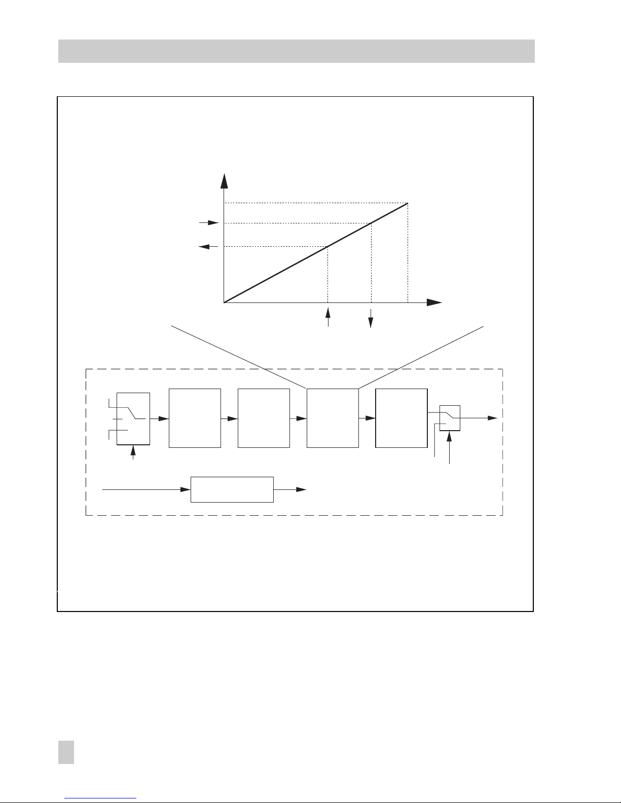
Fig. 14 ⋅Analog Output Function Block
RCAS_IN
CAS_IN
READBACK
PV
OUT
100 %
0 %
0 ˚C
PV_SCALE
SP_LO_LIM<=SP<=SP_HI_LIM
SP
PV
SP
READBACK
OUT
XD_SCALE
MODE_BLK
OUT
MODE_BLK
(manual)
SP
(e.g. in °C)
(e.g. in %)
Set point
ramps
Sp_RATE_DN
Sp_RATE_UP
PV, XD
scaling
XD_SCALE
PV_SCALE
XD, PV scaling
XD_SCALE, PV_SCALE
Set point
limits
SP_HI_LIM
SP_LO_LIM
Output
options
IO_OPTS
60
EB 8383-1 EN
Parameter description
Page 61

Parameters of the Analog Output Function Block
ALERT_KEY
S
Index: 4
Access: r, w
Input:
Default:
The id entifi ca ti on numb er of the pla nt unit. T hi s inform at io n may be us ed in th e
fieldbus host system for sorting alarms and events.
1...255
0
Note: The value 0 (default) is not a tolerated value and is therefore rejected with an
error message when writing to the device.
BKCAL_OUT
D
Index: 25
Access: r
Shows the analog output value and status which is passed on to BKCAL_IN of the
ups tr ea m funct io n block w it h a casc ad e contr ol . T his val ue prev en ts res et wi ndup an d
provides bumpless transfer to closed loop control.
BLOCK_ALM
D
Index: 30
Access: r, w
Sho ws th e curre nt block s ta tu s with i nf or mation ab ou t exist in g c onfigu ra tion,
hardware or system errors including data about when the alarm was generated (date
and time) due to an error occurring.
Note : A dd itiona lly, the ac tive bl oc k alarm ca n b e manua ll y ackno wl edged i n t his
parameter group.
BLOCK_ERR
D
Index: 6
Access: r
Display:
Shows the active block error.
OUT OF SERVICE The block mode is O/S.
CONFIGURATION_ERROR
INPUT FAILURE PV (position feedback) has BAD status, e.g. because
the Tr ansduc er Bl ock is i n O /S mo de.
OUTPUT FAILURE Correction value OUT cannot be issued, e.g. because
the Transducer Block is not initialized or is in LO mode.
CAS_IN
N
Index: 17
Access: r, w
Sho ws /d etermi ne s t he anal og refe re nce var iable a nd it s statu s t aken ov er from an
ups tr ea m conne ct ed func ti on block.
CHANNEL
S
Index: 22
Access: r, w in O/S
Default:
Assi gn ment am on g t he outp ut of each Ana lo g Outpu t F un ction B lo ck and the lo gical
hardware channels (Transducer Block).
1
Note: CHANNEL must be set to a valid value before the AO Function Block can be put
int o o pe ration. Th is valu e m ust be s et to "1 " as the re is only on e Tr ansdu ce r B lo ck
(Standard Advanced Positioner Valve) available in the Type 3787.
FSTATE_TIME
S
Index: 23
Access: r, w
Default:
The ti me in seco nd s f rom det ec ti on of a f au lt of the val id set poi nt fo r t he AO Fu nc ti on
Blo ck in the cur re nt mode u nt il the fa ul t state is ac tivate d. If the f au lt still e xi sts aft er th is
time interval has elapsed, the fault state is activated.
0
Note : T he faul t s ta te of the AO Fu nction Bl oc k is det er mi ned in I O_ OPTS of t hi s b lock.
EB 8383-1 EN
61
Parameter description
Page 62

FSTATE_VAL
S
Index: 24
Access: r, w
Input:
Default:
Dete rm ines se t p oi nt for t he AO Functio n B lock to b e u sed whe n t he faul t s ta te is
activated.
Value and range of PV_SCALE ±10 %
0
Note: This value is used when the option "Fault State to value" is selected in IO_OPTS.
GRANT_DENY
D
Index: 13
Access: r, w
Gran t o r limit th e a ccess o f a fi eldbu s h os t syste m t o t he field d ev ice.
Note: This parameter is not evaluated by the Type 3787.
IO_OPTS
S
Index: 14
Access: r, w in O/S
Option:
Use d to selec t the inpu t/out put block processi ng of t he AO Block
SP-PV Track in MAN SP follows PV in (ACTUAL_MODE) MAN mode
SP-PV Track in LO SP follows PV in (ACTUAL_MODE) LO mode
SP Tra ck retai ned tar ge t: SP foll ow s RCAS_I N o r C AS _I N depen di ng on the preset
TARGET_MODE in (ACTUAL_MODE) LO or MAN mode.
This op ti on has p ri or ity ove r S P_ PV Track in MA N / LO mo des.
Increase to close Inversion of output value to the Transducer Block
(corresponds with the direction of action).
Fault State to value When the fault state is activated, FSTATE_VAL is used as
the set point (see FSTATE_VAL, FSTATE_TIME).
Use Fault State Value on restart:
When the device is sta r t ed u p, F STATE_VAL is used as t he
set point default until there is a valid value.
Tar get to MAN if Fa ult Sta te ac tivate d:
When the f ault st ate i s act ivated , the TAR GET_MO D E is se t
to MAN. The original target mode is lost. After leaving the
fault state, the block remains in MAN and the user must set
it to the required mode.
Use P V f or BKCAL_O UT:
PV is returne d inste ad of the ope ra ti ng set po in t o ver
BKCA L _OUT. If t he opti on OUT RE A DBACK is s elect ed i n
FEATU RES_SE L of the Resourc e Blo c k, t he c urren t valve stem
position is then reported back over BKCAL_OUT.
62
EB 8383-1 EN
Parameter description
Page 63

MODE_BLK
N
Index: 5
Access: r, w
Display:
Shows the actual mode of the AO Block, the target modes, permitted modes supported
by the AO Block and normal mode.
RCAS
CAS
AUTO
MAN
O/S
The AO Block supports the following modes:
O/S
(Ou t of Ser vice)
The A O a lgorit hm of th e block is no t execu te d. The la st valu e o r the va lu e
det er mi ned dur in g activ e f ault st at e h andli ng is issu ed at the O UT pa ramete r.
MAN
(Ma nual)
The o ut pu t value of th e AO Blo ck ca n be dir ec tly pre set by th e u ser ove r t he
OUT parameter.
AUTO
(Au tomat ic)
The set point preset by the user is used on executing the AO Block via the
SP parameter.
CAS
(Cascade)
The AO Function Block receives the reference variable for internal calculation
of the manipulated variable directly from an upstream connected Function
Block via CAS_IN. The AO Block is executed.
RCAS
(Remote cascade)
The AO Function Block receives the reference variable for internal calculation
of the manipulated variable directly from the fieldbus host system via
CAS_IN. The AO Block is executed.
OUT
N
Index: 9
Access: r, w in MAN, O /S
Shows the manipulated variable, value, limit and status of the AO Function Block.
Not e: If the MAN mode in M ODE_BLK is selected, t he output value OUT can be
entered manually here. The unit used is taken over by the XD_SCALE parameter
gro u p. T he inp ut ran ge c o rresp onds to OUT_ SCALE ±10 %.
PV
D
Index: 7
Access: r
Shows the process variable including status used for the function blocks. The unit used
is ta ken o ver by t he P V_SCALE param e ter group.
Note : If the option OUT R EADBAC K in F EATURES _ SEL in t he R esourc e Blo ck is
activated, PV contains the current valve stem position (corresponding to
FINAL_POSITION_VALUE).
PV_SCALE
S
Index: 11
Access: r, w in MAN, O /S
Default:
Definition of the range (lower range and upper range value), engineering unit and
number of digits behind the decimal place of the process variable (PV).
0...100 %
RCAS_IN
N
Index: 26
Access: r, w
Shows and used to input the analog reference variable (value and status) provided by
the fieldbus host system and used as the set point to calculate the manipulated variable.
Note: This parameter is only active in RCAS mode.
EB 8383-1 EN
63
Parameter description
Page 64

RCAS_OUT
D
Index: 28
Access: r
Shows the analog reference variable (value and status) after ramping.
This value is made available to the fieldbus host system to perform back calculations
when th e opera ti ng mode ch anges o r w it h limi te d s ignal s.
Note: This parameter is only active in RCAS mode.
READBACK
D
Index: 16
Access: r
Sho ws cu rrent v al ve stem po sition. The val ue is calc ul ated fr om
FINAL_POSITION_VALUE of the associated Transducer Block. The unit used is taken
over by the XD_SCALE parameter group.
SHED_OPT
S
Index: 27
Access: r, w
Option:
Default:
Use d to selec t the action to be taken w hen t he monitoring time is ex ceeded (see
SHED_RCAS in Resource Block) during the checking of the link between the fieldbus
host sy stem an d t he AO Blo ck in RCAS mod e. Af ter the mo ni toring ti me has ela psed,
the AO B lock c hang es fr om RCA S mode to the mode sel ected he re. The ac tion t o be
taken after the fault state is completed is likewise determined.
Uninitialized
NormalShed_NormalReturn:
Chan ge s to nex t p os sible m od e, afte r l eaving th e error co nditio n,
returns to RCAS mode.
NormalShed_NoReturn:
Chan ge s to nex t p os sible m od e, afte r l eaving th e error co nditio n,
the block remains in this mode.
ShedToAuto_NormalReturn
Changes to AUTO mode, after leaving the error condition,
returns to RCAS mode.
ShedToAuto_NoReturn:
Changes to AUTO mode, after leaving the error condition,
the block remains in AUTO mode.
ShedToManual_NormalReturn:
Chan ge s to MAN m od e, after l ea ving th e e rror c on di tion,
returns to RCAS mode.
ShedToManual_NoReturn:
Chan ge s to MAN m od e, after l ea ving th e e rror c on di tion,
the block remains in MAN mode.
ShedToRetainedTarget_NormalReturn:
Change to next possible mode, after leaving the error condition,
returns to RCAS mode.
ShedToRetainedTarget_NoReturn:
Change to next possible mode, after leaving the error condition,
the block remains in this mode.
Uninitialized
Note:
Thi s par amet er is only activ e in t he AO Block in t he RC AS mod e. If it is set to
"Uninitialized", the AO Block cannot be put into the RCAS mode.
64
EB 8383-1 EN
Parameter description
Page 65

SIMULATE
D
Index: 10
Access: r, w
Usin g t he sim ul at ion the va lue and st at us of the proces s v ariabl e P V of the bl oc k can be
simulated.
Note:
Duri ng simu la tion, t he va lue of O UT is not pass ed onto th e Tr ansdu ce r B lock. T he
Tran sducer Bl oc k keeps th e last va li d valu e s to red bef or e the si mu lation wa s a ctivat ed .
The sim ulat ion ca n onl y be a ctivated by en abling th e swi tch in the device (s ee also
Resource Block).
SP
N
Index: 8
Access: r, w
in AU TO , M AN , O /S
Input:
Used to input the set point (reference variable) in AUTO mode.
The unit used is taken over by the PV_SCALE parameter group.
Value and range of the PV_SCALE ±10 %
SP_HI_LIM
S
Index: 20
Access: r, w
Input:
Default:
Used to input the high limit of the set point (reference variable).
Value and range of the PV_SCALE ±10 %
100
Note : If the high limit of th e set p oint is c hanged in PV_S CALE, th is val ue sho uld be
adapted accordingly.
SP_LO_LIM
S
Index: 21
Access: r, w
Input:
Default:
Used to input t he lo w limit of th e s et poin t ( refere nc e varia ble).
Value and range of the PV_SCALE ±10 %
0
Note : If the low l imit of t he s et point is ch anged in P V _SCALE , thi s value should be
adapted accordingly.
SP_RATE_DN
S
Index: 18
Access: r, w
Default:
Used to input the ramp rate at which downward set point changes are acted on in
AUTO mode.
3402823466 x 10
38
Note: If the ramp rate is set to "0", the set point will be used immediately.
The ra te limiti ng will ap ply for o ut put bloc ks in AUTO a nd CA S m odes.
SP_RATE_UP
S
Index: 19
Access: r, w
Default:
Used to input the ramp rate at which upward set point changes are acted on in AUTO
mode.
3402823466 x 10
38
Note: If the ramp rate is set to "0", the set point will be used immediately.
ST_REV
N
Index: 1
Access: r
Shows the revision level of the static data.
Note:
The revision level will be incremented each time a static parameter is changed.
EB 8383-1 EN
65
Parameter description
Page 66

STATUS_OPTS
S
Index: 15
Access: r, w in O/S
Option:
Default:
Used to select available status options to determine the treatment and processing of the
status:
Uninitialized
Propagate Fault Backward
Status of the Transducer is passed on to the upstream connected
Block using the status of BKCAL_OUT.
Uninitialized
STRATEGY
S
Index: 3
Access: r, w
Default:
The s tr ategy f ie ld can b e u sed to i de nt ify gro up ing of bl oc ks to al lo w a faster an alysis
of the blocks. Enter the same number in the STRATEGY parameter of each block to
group blocks.
0
Note: This data is not checked or processed by the AO Function Block.
TAG_DESC
S
Index: 2
Access: r, w
Default:
For e nt ering a us er-sp ec if ic text of ma x. 32 charac te rs to cl ea rly ide nt ify and as sign
the block.
No text
UPDATE_EVT
D
Index: 29
Access: r
This al er t is gen er ated by an y chang e t o t he stat ic data, i nc luding da te and t im e.
XD_SCALE
S
Index: 12
Access: r, w in MAN, O /S
Default:
Definition of the range (lower range and upper range value) of the engineering unit
and the number of digits behind the decimal point of the manipulated variable (OUT).
Specified in [%], [mm] or [grad].
0.0...100.0 %
Note: On using [%], the value for OUT is scaled based on 100 %. For [mm] (globe
valves) or [ grad] (rotary valves) , the value currently set in RATED_TRAVEL in the
Transducer Block is scaled as 100 %.
66
EB 8383-1 EN
Parameter description
Page 67

7.4.3.2 PID Function Block (PID controller)
A PID Function Block includes the input channel processing, the PID control and the analog
output channel processing.
The configuration of the PID Block (PID controller) is dependent on each automation task.
Simple control loops, feedforward controls, cascade control and cascade control with limits
can be implemented in combination with a further controller block.
The following options exist for processing the measured variable within the PID Function
Block (PID controller):
Signal scaling, signal limits, control of the modes, feedforward control, limit control, alarm
detection and passing on the signal status.
The PID Block (PID controller) can be used for various automation strategies. The Block has a
flexible control algorithm which can be configured depending on the application.
The PID Block receives its set point depending on the operating mode (MODE_BLK) from the
CAS_IN, RCAS_IN or SP input variables. PV_SCALE, SP_HI_LIM, SP_LO_LIM, SP_RATE_UP
and SP_RATE_DN are used to form an internal operating set point.
The Block receives the actual value over the IN input variable. The process variable PV is
formed from this, taking into account the PV_SCALE and the filter of the first order PV_FTIME.
These values are fed to the internal PID algorithm. This algorithm consists of a proportional,
an integral and a derivative component. The manipulated variable is calculated from the set
point value SP, from the process variable PV (actual value) and from the system deviation.
The individual PID components are included in the calculation of the manipulated variable as
follows:
Proportional component:
The proportional component reacts immediately and directly when the set point SP or the
process variable PV (actual value). The manipulated variable is changed by the proportional factor GAIN. This change corresponds to the system deviation multiplied by the
gain factor. If a controller works only with a proportional component, the control loop
has a permanent system deviation.
Integral component:
The system deviation resulting from the calculation of the manipulated variable using the
proportional component is integrated over the integral component of the controller until it
is negligible. The integral function corrects the manipulated variable depending on the
size and duration of the system deviation. If the value for the integration time RESET is
set to zero, the controller works as a P or PD controller. The influence of the integral component on the control loop increases when the value of the integration time is reduced.
Derivative component:
In controlled systems with long delay times, e.g. in temperature control loops, it makes
sense to use the derivative component RATE of the controller. Using the derivative compo-
EB 8383-1 EN
67
Parameter description
Page 68

nent RATE, the manipulated variable is calculated depending on the rate of change of the
system deviation.
An output value OUT is formed from the calculated manipulated variable corresponding to
the OUT_SCALE, OUT_HI_LIM and OUT_LO_LIM parameters. This output value can be
passed on to a downstream connected Function Block.
The status of the output value OUT can be influenced by the STATUS_OPTS parameter depending on the status of the input variable of the PID Block. This allows, for example, the
fault state of a downstream connected output block to be activated.
The BYPASS parameter allows the internal set point to be directly transferred to the correction value.
Feedforward is possible over the FF_VAL input variable. TRK_IN_D and TRK_VAL allow the
output value to be directly tracked.
Fig. 15 ⋅PID Function Block (PID controller)
RCAS_IN
CAS_IN
FF_VAL
TRK_VAL
SP
TRK_IN_D
OUT
PV
IN
+–
SP
ON
OFF
Bypass
Filter
PV_TIME
Scaling
PV_SCALE
Scaling
FF_SCALE
FF_GAIN
PID
algorithm
GAIN
RATE
RESET
Feedforward Tracking
Set point
ramps
Sp_RATE_DN
Sp_RATE_UP
PV scaling
PV_SCALE
Set point
limits
SP_HI_LIM
SP_LO_LIM
Output
limits
OUT_HI_LIM
OUT_LO_LIM
Scaling
TRK_SCALE
Scaling
OUT_SCALE
68
EB 8383-1 EN
Parameter description
Page 69

Parameters of the PID Function Block
ACK_OPTION
S
Index: 46
Access: r, w
Option:
Default:
This parameter allows you to choose whether an alarm should be automatically
acknowledged in the device, i.e. without any influence from the fieldbus host system.
Undefined No option
HI_HI_ALM High high alarm
HI_ALM High alarm
LO_LO_ALM Low low alarm
LO_ALM Low alarm
DV_HI_ALM Limit alarm for upper range deviation
DV_LO_ALM Limit alarm for lower range deviation
BLOCK ALM Block alarm
Undefined
Note:
The alarm is sent to the fieldbus host system, but not acknowledged by it.
ALARM_HYS
S
Index: 47
Access: r, w
Input:
Default:
Used to input t he hy steres is for th e high an d low al ar m l imits.
The al ar m condi ti on s remai n a ctive a s l ong as t he me asure d v alue is wi thin th e
hysteresis. The hysteresis value has an effect on the following alarm limits of the PID
Function Block:
HI_HI_LIM
HI_LIM
LO_LO_LIM
LO_LIM
DV_HI_LIM
DV_LO_LIM
0...50 %
0.5 %
Note: The hysteresis value in percent applies to the range of the PV_SCALE parameter
gro up in the PID Fu nc tion Bl oc k.
ALARM_SUM
S + D
Index: 45
Access: r, w
Display:
Shows the current status of process alarms in the PID Function Block
HI_H I_ AL M Viol at io n of the hi gh high al arm
HI_ALM Violation of the high alarm
LO_ LO _A LM Violat io n o f t he low l ow al arm
LO_ ALM Violation o f the low a larm
DV_H I_ AL M Vio la ti on of the limit al ar m f or the u pp er ran ge de viatio n
DV_L O_ ALM Viola ti on of the li mit ala rm fo r t he lowe r range de viatio n
BLOCK ALM Block alarm
Note: Additionally, the process alarm can be cleared in this parameter group.
EB 8383-1 EN
69
Parameter description
Page 70

ALERT_KEY
S
Index: 4
Access: r, w
Input:
Default:
The identification number of the plant unit. This information may be used in the
fieldbus host system for sorting alarms and events.
1...255
0
Note: The value 0 (default) is not a tolerated value and is therefore rejected with an
error message when writing to the device.
BAL_TIME
S
Index: 25
Access: r, w
Default:
Use d to input the time co nsta nt at which the integral term w ill m ove to obtain balan ce
when the output is limited (calculated manipulated variable > OUT_HI_LIM or <
OUT_LO_LIM).
0
Note: When 0 (default) is set, the balance is immediately reduced.
BKCAL_HYS
S
Index: 30
Access: r, w
Input:
Default:
Used to input th e h ystere sis val ue fo r the u pp er and l ow er limi ts of th e manip ulated
var ia ble ran ge OU T_HI_L IM an d OUT_LO _L IM.
If th e c alcula te d m anipu la ted var ia ble ex ce ed s or fal ls below t he range d ef ined by th e
range limits, this range violation is indicated in the OUT parameter and passed on to
the downstream connected blocks.
The range violation remains active as long as the value of the calculated manipulated
variable does not exceed or fall below the hysteresis value again.
0...50 %
0.5 %
BKCAL_IN
N
Index: 27
Access: r, w
Sho ws th e analo g i nput va lu e and st at us whic h i s t aken o ve r f rom the BK CA L_ OU T
parameter of the downstream connected Function Block with a cascade control. This
value provides bumpless transfer to closed loop control by tracking the output.
BKCAL_OUT
D
Index: 31
Access: r, w
Sho ws th e analo g i nput va lu e and st at us whic h i s passe d o n f rom the BK CA L_ IN
parameter of the upstream connected Function Block with a cascade control. This
value prevents reset windup and provides bumpless transfer to closed loop control by
tracking the output.
BLOCK_ALM
D
Index: 44
Access: r, w
Shows the current block status with information about existing configuration,
hardware or system errors including data about when the alarm was generated (date
and time) due to an error occurring.
Note: Additionally, the active block alarm can be manually acknowledged in this
parameter group.
BLOCK_ERR
D
Index: 6
Access: r
Display:
Sho ws th e activ e b lo ck erro r.
OUT OF SERVICE
CONFIGURATION_ERROR
70
EB 8383-1 EN
Parameter description
Page 71

BYPASS
S
Index: 17
Access: r, w in MAN, O /S
Option:
Default:
This parameter allows the calculation of the manipulated variable by means of the PID
cont ro l algor it hm to be s wi tched o n o r o ff .
Unintialized Same as ON
OFF Bypass switched off: the manipulated variable determined by the
PID c on tr ol alg or it hm is is su ed over th e O UT param et er.
ON BY PASS swi tc he d on: th e v alue o f t he re feren ce variab le SP is
issued directly over the OUT parameter.
OFF
Note: On setting "Uninitialized", the block remains in the "O/S" mode.
To activate the bypass (ON), the bypass must be e nabl ed in the CONTRO L_OPTS
parameter.
CAS_IN
N
Index: 18
Access: r, w
Shows/defines the analog reference variable and its status taken over from an
ups tr ea m conne ct ed Func ti on Block.
CONTROL_OPTS
S
Index: 13
Access: r, w in MAN, O /S
Option:
Default:
Used to select th e a vaila bl e contr ol ler opt io ns to determ in e the au to ma tion st ra te gy.
Bypass Enable
Direct Acting
Track Enable
Track in Manu al
PV fo r B KC AL _OUT
No OUT Limits in Manual
None
DV_HI_ALM
D
Index: 64
Access: r, w
Shows status of alarm for the high deviation including details about alarm time (date,
time) and about the value which triggered the alarm.
The controlled variable exceeds the reference variable by more than the value
determined in the DV_HI_LIM parameter.
Note : A dd itiona lly, the ac tive bl oc k alarm ca n b e manua ll y ackno wl edged i n t his
parameter group.
DV_HI_LIM
S
Index: 57
Access: r, w
Default:
Used to input the limit for the high deviation. If the controlled variable exceeds the
reference variable by this value, the deviation alarm DV_HI_ALM is generated.
3402823466 x 10
38
DV_HI_PRI
S
Index: 56
Access: r, w
Input:
Dete rm ines th e a ct ion to b e t ak en when th e high de viatio n a larm (DV _H I_ LIM) is
exceeded.
0 The violation of the limit for the high deviation is not evaluated.
1 No message issued when a violation of the limit for the high deviation occurs.
EB 8383-1 EN
71
Parameter description
Page 72

Default:
2 Rese rve d f or block a la rms.
3...7 The violation of the limit for the high deviation is issued with the
corresponding priority (3= low priority, 7= high priority) to notify the user.
8...15 The violation of the limit for the high deviation is issued with the
corresponding priority (8= low priority,15= high priority) as a critical
alarm.
0
DV_LO_ALM
D
Index: 65
Access: r, w
Shows status of alarm for the low deviation including details about alarm time (date,
time) and about the value which triggered the alarm.
The controlled variable falls below the reference variable by more than the value
determined in the DV_LO_LIM parameter.
Note: Additionally, the active block alarm can be manually acknowledged in this
parameter group.
DV_LO_LIM
S
Index: 59
Access: r, w
Default:
Used to input the limit for the low deviation. If the controlled variable falls below the
ref er ence va ri able by th is valu e, the l ow de viatio n a larm DV_ LO _A LM is ge ne rated .
-3402823466 x 10
38
DV_LO_PRI
S
Index: 58
Access: r, w
Input:
Default:
Dete rm ines th e a ct ion to be taken w he n t he low d ev iation al arm (DV_ LO _LIM) is
exceeded.
0 The violation of the limit for the low deviation is not evaluated.
1 No mes sa ge issu ed when a v io lation of th e limit fo r t he low d ev iation oc cu rs.
2 Rese rve d f or block a la rms.
3...7 The violation of the limit for the low deviation is issued with the
corresponding priority (3= low priority, 7= high priority) to notify the user.
8...15 The violation of the limit for the low deviation is issued with the
corresponding priority (8= low priority,15= high priority) as a critical
alarm.
0
FF_GAIN
S
Index: 42
Access: r, w in MAN, O /S
Default:
Used to input the gain of the feedforward control.
0
Note: The feedforward gain is multiplied by feedforward input (FF_VAL). The result is
added to the output value OUT.
FF_SCALE
S
Index: 41
Access: r, w in MAN, O /S
Default:
Defi nes the me as uring ra nge (lo w a nd high li mits), th e e nginee ring un it and the
number of digits behind the decimal point of the disturbance variable (FF_VAL).
0...100 %
72
EB 8383-1 EN
Parameter description
Page 73

FF_VAL
N
Index: 40
Access: r, w
Input:
Used to input a nd displa ys the fee df or wa rd value a nd status .
Range and unit of the FF_SCALE
Note: The feedforward input is multiplied by the gain (FF_GAIN) before it is added to
the calculated output value OUT.
GAIN
S
Index: 23
Access: r, w
Default:
Used to input the proportional gain (factor).
1.0
Note: The parameter must be set to a value unequal to 0, otherwise a configuration
error is set in the BL OCK_ERR parameter and th e block goes into O/S m ode.
GRANT_DENY
D
Index: 12
Access: r, w
Grant or deny access of a fieldbus host system to the field device.
Note: This parameter is not evaluated by the Type 3787.
HI_ALM
D
Index: 61
Access: r, w
Sho ws th e statu s o f t he alar m f or th e high al ar m limit (H I_ LIM), in cl uding de ta ils ab ou t
the a la rm timi ng (d ate, ti me ) a nd the va lu e whic h t ri ggere d t he alar m.
Note: The unit of the alarm status parameter is taken on by the PV_SCALE parameter.
Additionally, the active alarm can be manually acknowledged in this parameter group.
HI_HI_ALM
D
Index: 60
Access: r, w
Shows the status of the alarm for the high high alarm limit (HI_HI_LIM), including
det ai ls abou t t he alarm t im in g (date , t im e) and t he value w hi ch trig ge red the alarm.
Note: The unit of the alarm status parameter is taken on by the PV_SCALE parameter.
Additionally, the active alarm can be manually acknowledged in this parameter group.
HI_HI_LIM
S
Index: 49
Access: r, w
Input:
Default:
Inp ut of the a larm limit for the h igh high a larm (HI_H I_ALM ).
If the value PV exceeds this limit, the HI_HI_ALM alarm status parameter is issued.
Range and unit of the PV_SCALE
3402823466 x 10
38
HI_HI_PRI
S
Index: 48
Access: r, w
Input:
Default:
Dete rm ines th e a ct ion to b e t ak en when th e high hi gh alar m l im it (HI_ HI _L IM ) is
exceeded.
0 Th e vio latio n of the hi gh hi gh al arm limit is no t evaluat ed.
1 No mes sa ge issu ed when a v io latio n o f t he high hi gh alarm oc cu rs .
2 Rese rve d f or block a la rms.
3...7 The violation of the high high alarm is issued with the corresponding
prio ri ty (3= l ow pr iority, 7= high pr io rity) t o n ot if y the us er.
8...15 The violation of the high high alarm is issued with the
corresponding priority (8= low priority,15= high priority) as a critical alarm.
0
HI_LIM
S
Index: 51
Access: r, w
Input:
Default:
Inp ut of the a larm limit for the h igh warning al arm (HI_AL M). If the valu e PV e xceeds
this limit, the HI_ALM alarm status parameter is issued.
Range and unit of the PV_SCALE
3402823466 x 10
38
EB 8383-1 EN
73
Parameter description
Page 74

HI_PRI
S
Index: 50
Access: r, w
Input:
Default:
Det ermin es th e act ion to be ta ken when t he hi gh al arm limit (HI_L IM) is exc eeded.
0 The violation of the high alarm limit is not evaluated.
1 No message issued when a violation of the high alarm occurs.
2 Rese rve d f or block a la rms.
3...7 The violation of the high alarm is issued with the corresponding
priority (3= low priority, 7= high priority) to notify the user.
8...15 The violation of the high warning alarm is issued with the
corresponding priority (8= low priority,15= high priority) as a critical alarm.
0
IN
N
Index: 15
Access: r, w
Shows/determines the analog controlled variable with details about status and value.
LO_ALM
D
Index: 62
Access: r, w
Shows the status of the alarm for the low alarm limit (LO_LIM), including details about
the alarm timing (date, time) and the value which triggered the alarm.
Note: The unit of the alarm status parameter is taken over by the PV_SCALE
parameter.
LO_LO_ALM
D
Index: 63
Access: r, w
Shows the status of the alarm for the low low alarm limit (LO_LO_LIM), including
det ai ls about th e alarm ti mi ng (dat e, time) an d t he valu e w hich t ri gg ered t he alarm.
Note: The unit of the alarm status parameter is taken over by the PV_SCALE
parameter. Additionally, the active alarm can be manually acknowledged in this
parameter group.
LO_LO_LIM
S
Index: 55
Access: r, w
Input:
Default:
Inpu t o f t he alar m l imit for th e low lo w a la rm (LO_L O_ ALM).
If the PV value exceeds this limit, the LO_LO_ALM alarm status parameter is issued.
Range and unit of the PV_SCALE
-3402823466 x 10
38
LO_LO_PRI
S
Index: 54
Access: r, w
Input:
Default:
Det ermin es th e act ion to be ta ken when t he va lue falls bel ow th e low low alarm limit
(LO_LO_LIM) .
0 The vi ol ation o f t he low low al ar m limit is no t evalu at ed.
1 No mes sa ge issu ed when a v io lation of th e low lo w a larm occ ur s.
2 Rese rve d f or block a la rms.
3...7 The violation of the low low alarm is issued with the corresponding
priority (3= low priority, 7= high priority) to notify the user.
8...15 The violation of the low low alarm is issued with the
corresponding priority (8= low priority,15= high priority) as a critical alarm.
0
74
EB 8383-1 EN
Parameter description
Page 75

LO_LIM
S
Index: 53
Access: r, w
Input:
Default:
Inp ut of the a larm limit for the l ow alarm (LO_AL M).
If the PV value exceeds this limit, the LO_ALM alarm status parameter is issued.
Range and limit of the PV_SCALE
-3402823466 x 10
38
LO_PRI
S
Index: 52
Access: r, w
Input:
Default:
Dete rm ines th e a ct ion to b e t ak en when th e valu e f al ls bel ow th e low al ar m l imit
(LO_LIM).
0 The violation of the low alarm limit is not evaluated.
1 No mes sa ge issu ed when a v io latio n o f t he lo w alar m o cc ur s.
2 Rese rve d f or block a la rms.
3...7 The violation of the low alarm is issued with the corresponding
prio ri ty (3= l ow pr iority, 7= high pr io rity) t o n ot if y the us er.
8...15 The violation of the low alarm is issued with the corresponding priority
(8= low priority,15= high priority) as a critical alarm.
0
MODE_BLK
S
Index: 5
Access: r, w
Display:
Sho ws th e actua l o pe ratin g m od e o f t he PID B lo ck, the ta rg et mode s, permit te d m od es
supported by the PID Block and normal operating mode.
ROUT
RCAS
CAS
AUTO
MAN
OOS
The PI D B lo ck supp or ts th e follo wi ng modes :
O/S
(Ou t of Ser vice)
The PID Algorithm of the Block is not executed. The last value or the value
determined during the active state fault is issued at the OUT parameter.
MAN
(Manual)
The out put value of the Block can be preset by the user d irec tly ov er th e
OUT parameter.
AUTO
(Au tomat ic)
The set point preset by the user is used on executing the PID algorithm via the
SP parameter.
CAS
(Cascade)
The PID Function Block receives the reference variable for internal calculation
of the manipulated variable directly from an upstream connected Function
Block via CAS_IN. The internal PID algorithm is executed.
RCAS
(Remote cascade)
The PID Function Block receives the reference variable for internal calculation
of the manipulated variable directly from the fieldbus host system via
RCAS_IN. The internal PID algorithm is executed.
ROUT
(Remote output)
The PID Function Block receives the reference variable for internal calculation
of the manipulated variable directly from the fieldbus host system via
ROUT_IN. The manipulated variable is reissued over the OUT parameter,
without executing the internal PID algorithm.
EB 8383-1 EN
75
Parameter description
Page 76

OUT
N
Index: 9
Access: r, w in MAN, O /S
Sho ws th e m anipu la te d vari ab le, val ue, lim it and stat us of the P ID Fu nc tion Bl oc k.
Note : If the M AN mode in MOD E_BLK is s elect ed, t he out put v alue OUT c an b e
entered manually here. The unit used is taken on by the OUT_SCALE parameter
group. The input range corresponds to OUT_SCALE ±10 %.
OUT_HI_LIM
S
Index: 28
Access: r, w
Input:
Default:
Used to input the maximum value of the analog manipulated variable (OUT).
Range of OUT_SCALE ±10 %, unit of OUT_SCALE
100
OUT_LO_LIM
S
Index: 29
Access: r, w
Input:
Default:
Used to input the minimum value of the analog manipulated variable (OUT).
Range of OUT_SCALE ±10 %, unit of OUT_SCALE
0
OUT_SCALE
S
Index: 11
Access: r, w in MAN, O /S
Default:
Defines the range (lower range and upper range), the engineering unit and the
number of digits behind the decimal point of the manipulated variable (OUT).
0...100 %
PV
D
Index: 7
Access: r
Shows the process variables, including the status, used for executing the block.
Note : The unit used is taken ov er b y the PV_SCALE parame ter group.
PV_FTIME
S
Index: 16
Access: r, w
Default:
Used to input th e f ilter t im e const an t ( in seco nd s) of the di gital f il ter of fi rs t o rder.
This ti me is re qu ired t o a ll ow 63 % of a c ha nge of t he co nt rolle d v ariabl e t o b ecome
effec ti ve at the in put IN in the PV va lue.
0 s
PV_SCALE
S
Index: 10
Access: r, w in MAN, O /S
Default:
Defines the range (lower range and upper range), the engineering unit and the
number of digits behind the decimal point of the process variable (PV).
0...100 %
RATE
S
Index: 26
Access: r, w
Default:
Used to input the time constant for the derivative function.
0 s
RCAS_IN
N
Index: 32
Access: r, w
Used to input and display the analog reference variable (value and status) provided by
the fieldbus host system and used as the set point to calculate the manipulated variable.
Note: This parameter is only active in the RCAS mode.
RCAS_OUT
D
Index: 35
Access: r
Shows the analog reference variable (value and status) after ramping.
This value is provided by the fieldbus host system to perform back calculations when
the operating mode changes or with limited signals.
Note: This parameter is only active in the RCAS mode.
76
EB 8383-1 EN
Parameter description
Page 77

RESET
S
Index: 24
Access: r, w
Default:
Used to input the time constant for the integral function.
3402823466 x 10
38
(maximum possible value)
Note: The integral function is cleared by setting to 0 seconds.
ROUT_IN
N
Index: 33
Access: r, w
Used to input and display the manipulated variable (value and status) provided by the
fieldbus host system.
Note: This parameter is only active in ROUT mode.
ROUT_OUT
D
Index: 36
Access: r
Sho ws th e analo g r eferen ce vari ab le (val ue and sta tu s) whic h i s suppl ie d via t he
ROUT_IN parameter.
This value is made available to the fieldbus host system to perform back calculations
whe n t he operat in g mode c ha nges or wi th limi te d s ignal s.
Note: This parameter is only active in ROUT mode.
SHED_OPT
S
Index: 34
Access: r, w
Option:
Used to select th e a ction t o b e t aken wh en the mon it or ing tim e i s exceed ed (see
SHED_RCAS in Resource Block) during the checking of the link between the fieldbus
host system and the PID Block in RCAS or ROUT mode. After the monitoring time has
ela ps ed, the PI D B lock ch an ges fro m R CA S o r ROUT mo de to th e mode se lected he re.
The action to be taken after the fault state is completed is likewise determined.
Uninitialized
NormalShed_NormalReturn:
Chan ges to ne xt po ssibl e m od e, afte r l eaving the err or
condition, returns to RCAS or ROUT mode.
NormalShed_NoReturn:
Chan ges to ne xt po ssibl e m od e, afte r l eaving the err or
condition, the block remains in this mode.
ShedToAuto_NormalReturn
Changes to AUTO mode, after leaving the error
condition, returns to RCAS or ROUT mode.
ShedToAuto_NoReturn:
Changes to AUTO mode, after leaving the error
condition, the block remains in AUTO mode.
ShedToManual_NormalReturn:
Chan ges to MA N m od e, after leavin g t he erro r
condition, returns to RCAS or ROUT mode.
ShedToManual_NoReturn:
Chan ges to MA N m od e, after leavin g t he erro r
cond it ion, th e b lo ck rem ai ns in MAN mo de .
ShedToRetainedTarget_NormalReturn:
Chan ges to ne xt po ssibl e m od e, afte r l eaving the err or
condition, returns to RCAS or ROUT mode.
ShedToRetainedTarget_NoReturn:
Chan ges to ne xt po ssibl e m od e, afte r l eaving the err or
condition, the block remains in this mode.
EB 8383-1 EN
77
Parameter description
Page 78

Default: Uninitialized
Note : T hi s para me ter is o nl y a ctive i n t he PID B lo ck in the R CA S a nd ROUT m od es . If it
is se t t o " Uninit ia lized" , t he PID B lo ck cannot be placed in to RCAS or R OU T m od es.
SP
N
Index: 8
Access: r, w
in AUTO, MAN, O/S
Input:
Used to input the set point (reference variable) in AUTO mode.
Value and range of the PV_SCALE ±10 %
SP_HI_LIM
S
Index: 21
Access: r, w
Input:
Default:
Used to input the upper range of the set point (reference variable).
Value and range of the PV_SCALE ±10 %
100
Note : If the lower ra nge settin g is c hange d in P V_SCALE , thi s value should be adapte d
accordingly.
SP_LO_LIM
S
Index: 22
Access: r, w
Input:
Default:
Used to input the lower range of the set point (reference variable).
Value and range of the PV_SCALE ±10 %
0
Note: If the lower range setting is changed in PV_SCALE, this value should be
adapted accordingly.
SP_RATE_DN
S
Index: 19
Access: r, w
Default:
Used to input the ramp rate at which downward set point changes are acted on in the
operating mode AUTO.
3402823466 x 10
38
Note : I f t he ramp ra te is se t t o " 0" , t he set po in t w ill be us ed immed iately. Th e rate l im it
is active for control blocks in the AUTO mode only.
SP_RATE_UP
S
Index: 20
Access: r, w
Default:
Used to input the ramp rate at which upward set point changes are acted on in AUTO
mode.
3402823466 x 10
38
Note : I f t he ramp ra te is se t t o " 0" , the se t p oi nt will be used im me diatel y. The ra te limit
is active for control blocks in the AUTO mode only.
ST_REV
S
Index: 1
Access: r
Shows the revision level of the static data.
Note : T he revi si on leve l w ill be in cremen te d each t im e a static pa ramete r i s c hange d.
78
EB 8383-1 EN
Parameter description
Page 79

STATUS_OPTS
Index: 14
Access: r, w in O/S
Option:
Default:
Used to select available status options to determine the treatment and processing of the
status:
Uninitialized
IFS if Bad IN Fault state of the downstream connected AO Function Block
ini ti at ed, if t he co ntroll ed vari ab le (IN) ch an ges the st atus to BA D.
IFS if Bad CAS_IN Fault state initiated if the external reference variable (CAS_IN)
changes to status to BAD.
Use Uncertain as Good
The status UNC ERTAIN is use d as G OOD.
Tar get In Ma nu al if Ba d I N
Transition to MAN mode if the controlled variable changes the
status to BAD.
Uninitialized
STRATEGY
S
Index: 3
Access: r, w
Default:
The str ateg y field ca n be u sed to ide ntify grou ping o f blo cks to allo w a faster anal ysis
of the blocks. Enter the same number in the STRATEGY parameter of each block to
group blocks.
0
Note : T his dat a i s not che ck ed or pr oc essed b y t he PID Fu nc tion Bl oc k.
TAG_DESC
S
Index: 2
Access: r, w
Default:
For ent erin g a us er-speci fic te xt of max. 32 charac ters to clearl y identif y and assi gn
the block.
No text
TRK_IN_D
N
Index: 38
Access: r, w
Shows/determines the discrete input (value and status) which initiates external or
out put tracking. After init iatin g tra cking, th e mode is c hanged to LO. D uring whi ch,
the manipulated variable at the output OUT takes over the value predetermined via the
input TRK_VAL.
TRK_SCALE
S
Index: 37
Access: r, w in MAN, O /S
Default:
Defi nes the ra nge (lo we r range an d upper range) , t he engin ee ring un it and the
number of digits behind the decimal place of the external track value (TRK_VAL).
0...100 %
TRK_VAL
N
Index: 39
Access: r, w
Shows/determines the analog input value and its status entered from another Function
Block for external tracking function.
UPDATE_EVT
D
Index: 43
Access: r
Thi s a le rt is gene rated b y a ny change to th e stati c b lock da ta , i ncludi ng date an d t ime.
EB 8383-1 EN
79
Parameter description
Page 80

7.5 Other parameters
7.5.1 Stale counter
The stale counter is used to assess the "quality" of a process variable received via a cyclically configured link (publisher subscriber link).
The process variables that are "connected" among various function blocks are transferred
using these links.
For this purpose, the preceding block (Publisher) sends the process variable on the bus at a
defined point in time. The successive block(s) (subscriber) "listen" at this point in time on the
bus. The receiving blocks check whether there is a valid value at the configured point in time.
A value is valid when it has the status "Good" at the expected point in time.
The stale counter defines how many successive stale (bad) values are accepted until the fault
state mechanism of the block is enabled.
When the stale counter is set to "0", this monitoring function is cleared.
7.5.2 Link objects
Link objects are used to link Function Block inputs and outputs (configurable cyclic links).
22 link objects can be configured for each positioner.
7.5.3 LAS capabilities
The number of projectable links and schedules is matched to the requirements and possibilities in the DeltaV System from FISHER-ROSEMOUNT.
Functioning as LAS the positioner can support the following:
1 schedule
1 subschedule
25 sequences per subschedule
25 elements per sequence
80
EB 8383-1 EN
Parameter description
Page 81

8. Diagnostic messages
8.1 Messages of the XD_ERROR_EXT parameter (Transducer Block)
Failure mechanics
This message is issued when the entered rated travel is not reached on initialization.
- Check mechanics and pneumatics in the valve
- Compare the specifications in the Transducer Block, which describe the valve as well as
the actuator and the mechanical structure, with the actual valve.
Reinitialize.
Failure in measurement
The internal A/D converter does not work properly within its time interval, or the
measured values are outside of the physical measured range limit of the A/D converter. If
a warm start does not reset the data, repair is necessary.
Not initialized
The device has not been initialized.
Selfcalibration failed
Initialization could not be successfully completed. Exact details about the causes are supplied by the SELF_CALIB_STATUS parameter.
Zero point error
This message indicates any changes exceeding or falling below the value determined during the initialization or zero calibration by more than
+ 5%.
Possible sources of error:
Worn-out valve plug/seat
Impurities between valve plug/seat
Automatic reset after initialization has been successfully completed.
Internal control loop disturbed
This message is issued when the positioner is not able to control in the set delay time
within the set tolerance band.
Reset using SELF_CALIB_CMD - "Reset Control Loop Fault".
Travel time exceeded
The travel time determined during initialization has been exceeded.
EB 8383-1 EN
81
Diagnostic messages
Page 82

Forced venting active
Forced venting is activated, i.e. the signal at terminals +81 and -82 is smaller than 3V.
The control valve moves to the fail-safe position irrespective of the control loop. It is automatically reset as soon as there is a 6V to 24 V DC signal at terminals +81 and -82.
Device under Selftest
This message is issued when the device is undergoing initialization or electric zero calibration.
Total valve travel limit exceeded
The current value for the total valve travel exceeds the entered or preset limit. Reset using
"SELF_CALIB_CMD = Reset total valve travel".
8.2 Messages of the XD_ERROR parameter (Transducer Block)
Unspecified Error
The device has not been initialized or the total valve travel has been exceeded.
General Error
No production calibration completed.
Calibration Error
This message is issued when a zero point error occurs, the control loop is disturbed or an
error occurred during initialization.
Calibration Error
Error on transmitting the characteristic to the device.
Automatic reset after a correct characteristic has been transmitted.
Electronics Failure
This message is issued if a defect is detected in the electronics module during the cyclic
check. Repair necessary.
Mechanical Failure
This message is issued when the entered rated travel is not at least reached on initialization.
82
EB 8383-1 EN
Diagnostic messages
Page 83

- Check mechanics and pneumatics in the valve
- Compare the specifications in the Transducer Block, which describe the valve as well as
the actuator and the mechanical structure, with the actual valve.
Reinitialize.
Data Integrity Error
Checksum error
Algorithm Error
Set point value - actual value error
8.3 Messages of the SELF_CALIB_STATUS parameter (Transducer Block)
Proportional band restricted too much
Even the smallest permissible pulses still cause excessive changes in travel. Initialization
aborted.
Possible sources of error:
Supply pressure too high
Signal pressure throttle missing in actuator with a small volume
Mechanical failure, especially with attachment according to IEC 60534-6 (NAMUR)
If a booster valve is mounted with an actuator with a large volume, the bypass should
be opened further.
EB 8383-1 EN
83
Diagnostic messages
Page 84

Dimensional drawing
39
35
14
198
78.5
40
86
30.5
164
150
27
14
28
56 58
N1=113
N2=200
39
50
78.5
45
50
82
150
164
27
75
56
50
86
46
28.5
28.5
Output 1 (A1)
Output 2 (A2)
Supply (Z)
Output (38)
Supply (9)
M20 x1.5
Direct attachment
Pneumatic connections
G 1/4 or NPT 1/4
Attachment with intermediate
piece for rotary actuators
Attach. IEC 60534-6 with adapter housing
Pneum. connection of reversing amplifier
84
EB 8383-1 EN
Page 85

EB 8383-1 EN
85
Page 86

86
EB 8383-1 EN
Page 87

EB 8383-1 EN
87
Page 88

88
EB 8383-1 EN
Page 89

EB 8383-1 EN
89
Page 90

90
EB 8383-1 EN
Page 91

EB 8383-1 EN
91
Page 92

92
EB 8383-1 EN
Page 93

EB 8383-1 EN
93
Page 94

94
EB 8383-1 EN
Page 95

EB 8383-1 EN
95
Page 96

96
EB 8383-1 EN
Page 97

EB 8383-1 EN
97
Page 98

⋅
⋅ ⋅
⋅
2017-07
 Loading...