

Page 1
OWNERS MANUAL
POWER
AMPLIFIER
F1200 / F800
POWERBRIDGEPEAK CH 1 PEAK CH 2
F1200
600W X 2 STEREO
F800
400W X 2 STEREO
F1200 STEREO HIGH PERFORMANCE 1200WATT AMPLIFIER
POWERBRIDGEPEAK CH 1 PEAK CH 2
F800 STEREO HIGH PERFORMANCE 800WATT AMPLIFIER
ON
OFF
POWER
ON
OFF
POWER
®
Page 2

1
Table of Contents
Introduction 3
F1200 / F800 Features 4
Controls and Functions
Front Panel 5
Rear Panel 6
Setting Up and Using Your F1200 / F800 7
The F1200 / F800 Protection Circuitry 8
Bridged Mode 9
F1200 / F800 Connections 10
Specifications 12
Page 3

3
Thank you for purchasing the Samson F1200 / F800 Power Amplifier. The Samson F1200 / F800 is a
three-space stereo power amplifier which is optimized for live sound venues, commercial installations, DJ
set-ups and for driving small and medium-sized PA systems. Fan-cooled for maximum thermal protection, the F1200 delivers 600 watts of power per channel (or, in Bridged mode, 1200 watts), and the F800
provides 400 watts of power per channel (or, in Bridged mode, 800 watts), over the full frequency spectrum, from 20 Hz to 20 kHz. Combination connectors allow both 1/4" and RCA input connections; output
connections are provided on a combination banana plug and bare wire terminal connectors. The front
panel includes a Power switch and Power, dual channel Peak and Bridge LEDs.
In these pages, you’ll find a detailed description of the features of the F1200 / F800 power amplifier, as
well as a guided tour through its front and rear panels, step-by-step instructions for its setup and use,
and full specifications. You’ll also find a warranty card enclosed—please don’t forget to fill it out and mail
it in so that you can receive online technical support and so we can send you updated information about
these and other Samson products in the future.
With proper care adequate air circulation, your F1200 / F800 will operate trouble free for many years. We
recommend you record your serial number in the space provided below for future reference.
Serial number:
Date of purchase:
Should your unit ever require servicing, a Return Authorization number (RA) must be obtained before
shipping your unit to Samson. Without this number, the unit will not be accepted. Please call Samson at
1-800-3SAMSON (1-800-372-6766) for a Return Authorization number prior to shipping your unit. Please
retain the original packing materials and if possible return the unit in the original carton and packing
materials.
Introduction
Page 4

4
F1200 / F800 Features
The Samson F1200 / F800 power amplifier utilizes the latest technology in professional power amplifier
design. Here are some of its main features:
• The F1200 delivers 600 watts of power per channel into 4 ohms. In the F800 delivers 400 watts of
power per channel into 4 ohms.
• In Bridged mode (linking both channels) the F1200 provides 1200 watts into 8 ohms and the F800
provides 800 watts into 8 ohms.
• Clean, crisp sound - Impressive audio specifications such as 0.05% THD+N (typ), dynamic range of
<100 dB, crosstalk of 65 dB, and frequency response of 20 Hz to 20 kHz guarantee ultra-clean
sound quality.
• Unique stable bipolar circuit design that continuously keeps DC output during idling at or near 0 volts
(thus keeping idle speakers at their 0 point).
• Forced air cooled by and internal fan, for reliable cooling without thermal and overheating problems.
• Protection relay circuitry that guards against overheating or faulty wiring conditions and also prevents
“thumps” when powering on or off. This means that you can use the F1200 / F800 with a single
power strip into which a mixer or other audio devices are connected, without danger of damage to
connected speakers.
• Input connectors for each channel accommodate both balanced 1/4" TRS and RCA plugs, and combination banana plug and shrouded binding posts for maximum flexibility.
• User-resettable circuit breaker for fast, easy startup following a power supply overload.
• The F1200 / F8000 can be mounted in any standard 19" rack (taking three rack spaces), making it
easy to integrate the into any fixed or traveling PA rig.
• Rugged construction (an all-steel chassis with a titanium finish and a lightweight anodized aluminum
heat sink) makes the F1200 / F800 eminently roadworthy.
• Three-year warranty.
Page 5
5
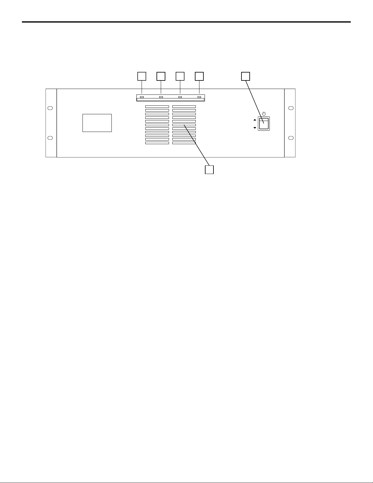
Controls and Functions
1: Power switch - Use this to power the F1200 / F800 on or off.
2: Power LED - Lights whenever the F1200 / F800 is powered on.
3: Peak LED (Ch1 Ch2) - The Channel 1 and Channel 2 Peak LEDs light whenever the input signal is
about to clip. This is not a problem if the Peak LEDs should light occasionally during peak levels, but if it
lights frequently, you may be overloading the F1200 / F800 and a distorted (“clipped”) signal is probably
being output. If this occurs back off the Output Level control of the device connected to the input of the
F1200 / F800 until the LEDs light only occasionally.
4: Bridge LED - This LED lights when the F1200 / F800 is in Bridged mode.
5: Air Intake Vents - These vents and the vents on the sides of the F1200 / F800 allow air to be drawn
over the heat sinks by the internal fan. This keeps the amplifier from over heating. Never block these
vents when the amplifier is on. Remove any dust that may build up on the protective screen.
13 3
ON
OFF
POWER
F1200
600W X 2 STEREO
42
POWERBRIDGEPEAK CH 1 PEAK CH 2
F1200 STEREO HIGH PERFORMANCE 1200WATT AMPLIFIER
5
Page 6

6
Controls and Functions
1: Fan Vents - These vents allow air to escape the F1200 / F800 via the internal fan. Make sure that
both the front and rear panels are kept free of all obstructions and that cool, fresh air is accessible at all
times. Also, try to ensure that the F1200 / F800 is used in a dust-free environment.
2: Circuit Breaker - This circuit breaker will trip if there is a fault with the mains voltage or if maximum
output is exceeded (very highly distorted). Push it in (once only!) to restart the amplifier.
3: AC input - Connect the power cable to a grounded AC outlet.
4: Banana Plug output connectors - Use these banana plug outputs to connect each channel of the
F1200 / F800 to 4- or 8-ohm loudspeakers using speaker cable fitted with banana jacks. Be sure to connect the loudspeaker correctly, with the red (+) terminal normally connected to the positive input of the
speaker and the black (ground) terminal normally connected to the negative input of the speaker. See
page 9 in this manual for more information about Bridged mode and pages 10 in this manual for full
speaker connection instructions.
5: Shrouded Binding Posts - Alternatively, you can use these to connect each channel of the F1200 /
F800 to 4- or 8-ohm loudspeakers using speaker wire. Be sure to connect the loudspeaker correctly,
with the red (+) terminal normally connected to the positive input of the speaker and the black (ground)
terminal normally connected to the negative input of the speaker. See page 9 in this manual for more
information about Bridged mode and pages 10 in this manual for full speaker connection instructions.
6: Input connectors - Connect incoming signal to the electronically balanced 1/4" TRS
(Tip/Ring/Sleeve) plugs, The TRS plugs are wired as follows: Tip (or Pin 2) hot, Ring (or Pin 3) cold, and
Sleeve (or Pin 1) ground. We recommend the use of balanced three-conductor cabling wherever possible (unbalanced two-conductor 1/4" plugs can also be inserted into these inputs, but you’ll get better signal quality and less outside noise and hum if you use balanced lines). The F1200 / F800 accepts input
levels of any strength but needs at least 0 dBu to achieve maximum power. Stereo signals should be
connected to both the Channel 1 and Channel 2 input jacks; however, when operating the F1200 / F800
in Bridged mode, use the Channel 1 input jack only. See page 10 and 11 in this manual for full interconnection instructions.
7: Bridged / Stereo - For normal operation, place this two-way switch in its right (“STEREO”) position.
When placed in its left (“BRIDGED”) position, the signal arriving at the Channel 1 input only is again
routed to both power amplifiers (again, the Channel 2 input is ignored), but the two power amplifiers are
bridged together, providing a full 1200 watts of power into 8 ohms (in the case of the F1200) or a full 800
watts of power into 8 ohms (in the case of the F800). When in bridged mode be sure to follow the output
diagram on the rear of the amplifier and connect the loudspeaker correctly with the red (+) terminal from
Channel one normally connected to the positive input of the speaker and the red (ground) terminal from
channel 2 normally connected to the negative input of the speaker. For more information, see the
“Bridged Mode” section on page 9 in this manual and the “F1200 / F800 Connections” section on pages
10 in this manual.
WARNING: Due to the extremely high power output of the F1200 / F800 when
used in Bridged mode, be sure to use only loudspeakers sufficiently rated to handle the resultant
wattage (in Bridged mode, these must be 8-ohm speakers).
2 3 1 5
AMPLIFIER
PUSH TO RESET
20A / 250V
~AC INPUT
115V / 60Hz, 800W
POWER
115V - 60Hz 800W
RATING
CAUTION
RISK OF ELECTRIC SHOCK
DO NOT OPEN.
MADE IN KOREA
SERIAL NUMBER
4
SAMSON
CAUTION
OUTPUT
CHANNEL 2
MINIMUM LOAD IMPEDANCE
STEREO
-
(4Ω/CHANNEL)
BRIDGED MONO
(8Ω)
AVIS ; RISQUE DE CHOC ELECTRIQUE NE PAS OUVRIR
DO NOT EXPOSE THIS EQUIPMENT TO RAIN OR MOISTURE.
CHANNEL 1
+
+
+
-
TO PREVENT SHOCK, DO NOT OPEN. NO USER SERVICEABEL PARTS INSIDE. REFER SERVICING TO
QUALIFIED SERVICE PERSONNEL. TO PREVENT FIRE OR SHOCK HAZARD. DO NOT EXPOSE TO
RAIN OR MOISTURE.
CAUTION ; REPLACE WITH THE SAME TYPE FUSE AS INDICATED.
UTILISER UN FUSIBLE DE RECHANGE DE MEME TYPE.
TIP RING SLEEVE
TIP +
CHANNEL 2
INPUT
(10KΩ / 0dBu)
RING SLEEVE GND
MODE SELECTOR
BRIDGED
-
INPUTS
TIP RING SLEEVE
TIP +
RING SLEEVE GND
STEREO
www.samsontech.com
INPUT
(10KΩ / 0dBu)
CHANNEL 1
6 6 7
Page 7

7
Setting Up and Using Your F1200 / F800
Setting up your F1200 / F800 is a simple procedure which takes only a few minutes:
1. Remove all packing materials (save them in case of need for future service) and
decide where the amplifier is to be physically placed—it can be used free-standing or
mounted in a standard 19" rack, requiring three rack spaces. When installed, make sure
the front, side and rear panels are unobstructed and that there is good ventilation around
the entire unit (we recommend the use of spacer panels, especially if multiple amplifiers
are used in a rack.
2. Set the rear panel Bridged / Stereo switch as desired (see the “Bridged Mode” section
on page 9 in this manual for more information).
3. Make the speaker connections, using the banana or shrouded binding post output connectors on the rear panel. It is never a good idea to power up any amplifier that is not
connected to loudspeakers. When operating in Stereo mode, any loudspeakers with a
minimum impedance load of 4 ohms (that is, 4 ohms or greater) can be used; however,
in Bridged mode, 8 ohm speakers
must be used. Be sure to connect the loudspeaker
correctly. In Stereo mode, make sure the red (+) terminal is connected to the positive
input of the speaker and the black (ground) terminal is connected to the negative input of
the speaker. In bridged mode make sure to follow the diagram on the rear of the amplifier. See page 9 in this manual for more information about Bridged mode and pages 10 in
this manual for full speaker interconnection instructions.
4. Next, make the signal input connections, using either the balanced 1/4
″ or RCA input
connectors on the rear panel (if operating the F1200 / F800 in Bridged mode, use the
Channel 1 input only—see page 10 and 11 in this manual for more information). If your
mixer or crossover network has balanced outputs, we recommend the use of three-conductor cabling and connectors (unbalanced two-conductor plugs can also be inserted into
the RCA inputs, but you’ll get better signal quality and less outside noise and hum if you
use balanced lines).
5. Connect the AC cable to a grounded AC socket. Because of the relay protection circuitry built into the F1200 / F800, you can even plug it into the same power strip that
other audio devices (such as a mixing console) are connected to. You can then turn on
all devices at once with the single power strip on-off switch, with no danger of damaging
connected speakers by generating “thumps.”
6. Press the front panel Power switch in order to turn on the F1200 / F800. The Power
LED will light LED will light.
7. Apply an input signal to the F1200 / F800 by gradually raising the output of the device
connected to the input of the F1200 / F800 until desired sound level is achieved observing the Peak LEDs. This is not a problem if the Peak LEDs light occasionally during peak
levels, but if it lights frequently, you may be overloading the F1200 / F800 and a distorted
(“clipped”) signal is probably being output. If this occurs back off the Output Level control
of the device connected to the input of the F1200 / F800 until the LEDs light only occasionally.
If you encounter difficulty with any aspect of setting up or using your S700 or S1000,
contact your local Samson dealer. If purchased in the United States, you can call
Samson Technical Support (1-800-372-6766) between 9 AM and 5 PM EST
Bridged / Stereo switch
Output connectors
Input connectors
LED meter
MODE SELECTOR
BRIDGED
STEREO
OUTPUT
CHANNEL 2
MINIMUM LOAD IMPEDANCE
STEREO
-
(4Ω/CHANNEL)
BRIDGED MONO
(8Ω)
CHANNEL 1
+
+
+
-
-
CHANNEL 2
INPUTS
TIP RING SLEEVE
TIP +
RING SLEEVE GND
MODE SELECTOR
INPUT
(10KΩ / 0dBu)
BRIDGED
TIP RING SLEEVE
TIP +
RING -
CHANNEL 1
SLEEVE GND
INPUT
STEREO
(10KΩ / 0dBu)
POWERBRIDGEPEAK CH 1 PEAK CH 2
Page 8

8
The F1200 / F800 Protection Circuitry
The F1200 / F800 Protection LED relay speaker connection circuitry is active
when the amp[[lifier is powered on or off. When the circuitry is active, and all
connected speakers are muted (provided with 0 volts DC), thus protecting them
and preventing any audible “thump” from occurring.
The following conditions will cause the Protection circuitry to activate:
•
Initial power-up: For approximately five seconds after initial power-up, the protection circuitry is activated and the speaker output is muted. If everything is
operating normally, you will hear an audible click at the conclusion of this brief
period, as the protection circuitry is deactivated and the F1200 / F800 begins
delivering signal to connected speakers (at which point you’ll hear a click).
•
Overheating: A temperature sensing device in the F1200 / F800 will cause the
protection circuitry to be activated (and the Protection LED to go on) whenever
the operating temperature of the unit rises above a safe level. To guard against
this problem, make sure the F1200 / F800 receives adequate ventilation on all
sides and that both the front and rear panels are unobstructed.
•
Severe overcurrent conditions: This occurs whenever the signal being input to
the F1200 / F800 rises to a level above 20% THD (Total Harmonic Distortion).
•
Shorted speaker cables: This will occur if, due to faulty wiring, the hot and
ground signals being output by the F1200 / F800 short one another.
•
Output impedance drops below 2 ohms: This can occur if the F1200 / F800 is
connected to inappropriate speaker systems (see the “Setting Up and Using
Your F1200 / F800” section on page 7 in this manual for more information).
•
DC voltage detected at speaker output: The most likely cause of this is an internal failure.
For further assistance, contact your local Samson dealer. If purchased in the
United States, you can call Samson Technical Support (1-800-372-6766)
between 9 AM and 5 PM EST.
Page 9

9
Bridged Mode
The F1200 / F800 provides a rear-panel switch that allows it to be used in either
a Stereo or Bridged mode. When this switch is placed in the “STEREO” (right)
position, the F1200 / F800 functions as a true stereo amplifier, where both of the
two independent amplifier channels (Channel 1 and Channel 2) can receive different input signals and produce independent output signals. However, when the
switch is placed in the “BRIDGED” (left) position, the Channel 1 inputs signal is
routed to both power amplifiers bridged together, producing a single output signal with a true 1200 watt output into a single 8 ohm channel (in the case of the
F1200) or a true 800 watt output into a single 8 ohm channel (in the case of the
F800).
The illustration on the right shows how this works. In Bridged mode, the polarity
(phase) of the Channel 2 output signal is reversed relative to that of the Channel
1 output signal. Both channels then process the same input signal, with the
speaker load connected so that power is derived from both channels. The effective voltage swing seen by the load is thus doubled, so that the power output is
doubled.
When using the F1200 / F800 in Bridged mode, be sure to connect your loudspeaker as shown in the illustrations on page 10 and 11 (and as silkscreened on
the rear panel), with the red (+) terminal of the Channel 1 output connected to
the negative input of the speaker and the red (+) terminal of the Channel 2 output connected to the positive input of the speaker.
Do not use the black
ground (-) output terminal of either channel (the speaker load must “float”
away from the amplifier chassis).
See pages 10 in this manual for interconnection diagrams when using the F1200
/ F800 in Bridged mode
WARNING: Bridged mode is to be used only when the F1200 / F800 is connected to an 8 ohm speaker load. Use of Bridged mode with speaker loads
of 4 ohms or less can result in severe damage to the unit due to excessive
heat and current limiting and will void your warranty!
Bridged Mode
Bridged / Stereo switch
MODE SELECTOR
BRIDGED
STEREO
OUTPUT
CHANNEL 2
MINIMUM LOAD IMPEDANCE
STEREO
-
(4Ω/CHANNEL)
BRIDGED MONO
(8Ω)
CHANNEL 1
+
+
-
-
+
INPUT
CHANNEL
1(+) OUTPUT
CHANNEL
2(+) OUTPUT
Page 10

10
The illustrations below show the required interconnections when using the F1200 / F800 in Stereo or Bridged modes.
F1200 / F800 Connections
Stereo Mode: (two speakers)
Bridged Mode:
(single speaker only)
MIXER
AMPLIFIER
PUSH TO RESET
20A / 250V
~AC INPUT
115V / 60Hz, 800W
POWER
RATING
115V - 60Hz 800W
CAUTION
RISK OF ELECTRIC SHOCK
DO NOT OPEN.
SERIAL NUMBER
MADE IN KOREA
CHANNEL 1/2
CHANNEL 3/4
0
0
0
•
+10
+15
+15
-15
-15
AUX 1L
HIGH
HIGH
0
0
0
•
+15
+10
+15
-15
-15
LOW
AUX 2R
LOW
0
0
R
L
• +10
• +10
BALANCE
LEVEL
LEVEL
CHANNEL 7/8CHANNEL 5/6
0
0
0
0
•
•
+10
+15
-15
+10
+15
-15
AUX 1L
HIGH
AUX 1L
HIGH
0
0
0
0
•
•
+15
+10
-15
+15
+10
-15
LOW
AUX 2R
AUX 2R
LOW
0
0
R
L
R
L
• +10
• +10
LEVEL
BALANCE
BALANCE
LEVEL
CHANNEL 11/12
CHANNEL 9/10
0
0
•
+15
-15
+10
AUX 1L
HIGH
0
0
•
+15
-15
+10
LOW
AUX 2R
0
R
L
• +10
LEVEL
BALANCE
CHANNEL 13/14
0
0
0
0
•
•
+10
+10
+15
-15
-15
AUX 1L
AUX 1L
HIGH
HIGH
0
0
0
0
•
•
+15
+10
+10
-15
-15
AUX 2R
LOW
LOW
AUX 2R
0
R
R
L
L
• +10
• +10
LEVEL
BALANCE
BALANCE
LEVEL
AUXILIARY RETURNS
CHANNEL 15/16
SAMSON
PL 1602 LINE MIX
0
0
0
•
•
+10
+15
+10
+15
-15
AUX 1L
AUX 1L
HIGH
0
0
0
•
•
+15
+10
+15
+10
-15
LOW
AUX 2R
AUX 2R
0
0
R
L
L
• +10
LEVEL
BALANCE
BALANCE
ER
0
+15
+15
•
+10
R
L
BALANCE
AUX 1/2 RETURN
0
0
0
•
R
+10
L
AUX3/4 RETURN
BALANCE
∞
∞
R
+10
0
RIGHT
LEFT
PHONES
POWER
SAMSON
CAUTION
OUTPUT
CHANNEL 2
MINIMUM LOAD IMPEDANCE
STEREO
-
(4Ω/CHANNEL)
BRIDGED MONO
(8Ω)
AVIS ; RISQUE DE CHOC ELECTRIQUE NE PAS OUVRIR
DO NOT EXPOSE THIS EQUIPMENT TO RAIN OR MOISTURE.
CHANNEL 1
+
+
+
-
+–
+–
-
TO PREVENT SHOCK, DO NOT OPEN. NO USER SERVICEABEL PARTS INSIDE. REFER SERVICING TO
QUALIFIED SERVICE PERSONNEL. TO PREVENT FIRE OR SHOCK HAZARD. DO NOT EXPOSE TO
RAIN OR MOISTURE.
CAUTION ; REPLACE WITH THE SAME TYPE FUSE AS INDICATED.
UTILISER UN FUSIBLE DE RECHANGE DE MEME TYPE.
CHANNEL 2
TIP RING SLEEVE
TIP +
RING SLEEVE GND
INPUTS
TIP RING SLEEVE
TIP +
RING SLEEVE GND
CHANNEL 1
MODE SELECTOR
INPUT
(10KΩ / 0dBu)
BRIDGED
INPUT
STEREO
(10KΩ / 0dBu)
www.samsontech.com
(CH 2) (CH 1)
EITHER INPUT
LOUDSPEAKER
AMPLIFIER
PUSH TO RESET
20A / 250V
~
AC INPUT
115V / 60Hz, 800W
POWER
RATING
(4 Ohm Min)
MIXER
115V - 60Hz 800W
CAUTION
RISK OF ELECTRIC SHOCK
DO NOT OPEN.
SERIAL NUMBER
MADE IN KOREA
SAMSON
CHANNEL 1/2
CHANNEL 3/4
0
0
0
•
+10
+15
+15
-15
-15
AUX 1L
HIGH
HIGH
0
0
0
•
+15
+10
+15
-15
-15
LOW
AUX 2R
LOW
0
0
R
L
•
+10
•
+10
BALANCE
LEVEL
LEVEL
CHANNEL 7/8CHANNEL 5/6
0
0
0
0
•
•
+10
+15
-15
+10
+15
-15
AUX 1L
HIGH
AUX 1L
HIGH
0
0
0
0
•
•
+15
+10
-15
+15
+10
-15
LOW
AUX 2R
AUX 2R
LOW
0
0
R
L
R
L
•
+10
•
+10
LEVEL
BALANCE
BALANCE
LEVEL
CHANNEL 11/12
CHANNEL 9/10
0
0
•
+15
-15
+10
AUX 1L
HIGH
0
0
•
+15
-15
+10
LOW
AUX 2R
0
R
L
•
+10
LEVEL
BALANCE
CHANNEL 13/14
0
0
0
0
•
•
+10
+10
+15
-15
-15
AUX 1L
AUX 1L
HIGH
HIGH
0
0
0
0
•
•
+10
+15
+10
-15
-15
AUX 2R
LOW
LOW
AUX 2R
0
R
R
L
L
•
•
+10
BALANCE
LEVEL
BALANCE
LEVEL
AUXILIARY RETURNS
CHANNEL 15/16
SAMSON
PL 1602 LINE MIX
0
0
0
•
•
+10
+15
+10
+15
-15
AUX 1L
AUX 1L
HIGH
0
0
0
•
•
+15
+10
+15
+10
-15
LOW
AUX 2R
AUX 2R
0
0
R
L
L
•
+10
+10
LEVEL
BALANCE
BALANCE
ER
0
+15
+15
•
+10
R
L
BALANCE
AUX 1/2 RETURN
0
0
0
•
R
+10
L
AUX3/4 RETURN
BALANCE
∞
∞
R
+10
0
RIGHT
LEFT
PHONES
POWER
LOUDSPEAKER
(4 Ohm Min)
SAMSON
CAUTION
OUTPUT
CHANNEL 2
MINIMUM LOAD IMPEDANCE
STEREO
-
(4Ω/CHANNEL)
BRIDGED MONO
(8Ω)
AVIS
; RISQUE DE CHOC ELECTRIQUE NE PAS OUVRIR
DO NOT EXPOSE THIS EQUIPMENT TO RAIN OR MOISTURE.
CHANNEL 1
+
+
+
-
TO PREVENT SHOCK, DO NOT OPEN. NO USER SERVICEABEL PARTS INSIDE. REFER SERVICING TO
QUALIFIED SERVICE PERSONNEL. TO PREVENT FIRE OR SHOCK HAZARD. DO NOT EXPOSE TO
RAIN OR MOISTURE.
CAUTION
; REPLACE WITH THE SAME TYPE FUSE AS INDICATED.
UTILISER UN FUSIBLE DE RECHANGE DE MEME TYPE.
-
CHANNEL 2
TIP RING SLEEVE
TIP +
RING SLEEVE GND
INPUTS
MODE SELECTOR
INPUT
(10KΩ / 0dBu)
BRIDGED
TIP RING SLEEVE
TIP +
RING SLEEVE GND
INPUT
STEREO
(10KΩ / 0dBu)
www.samsontech.com
CHANNEL 1
+ –
EITHER INPUT
(CH 1 ONLY)
LOUDSPEAKER
(8 Ohm Min)
Page 11

F1200 / F800 Connections
11
Stereo Mode:
(four speakers)
PUSH TO RESET
20A / 250V
~AC INPUT
115V / 60Hz, 800W
LOUDSPEAKER
(8 Ohm Min)
AMPLIFIER
POWER
115V - 60Hz 800W
RATING
CAUTION
RISK OF ELECTRIC SHOCK
DO NOT OPEN.
MIXER
SERIAL NUMBER
MADE IN KOREA
CHANNEL 1/2
CHANNEL 3/4
0
0
0
•
+10
+15
+15
-15
-15
AUX 1L
HIGH
HIGH
0
0
0
•
+15
+10
+15
-15
-15
LOW
AUX 2R
LOW
0
0
R
L
• +10
• +10
LEVEL
BALANCE
LEVEL
CHANNEL 7/8CHANNEL 5/6
0
0
0
0
•
•
+10
+15
-15
+10
+15
-15
AUX 1L
HIGH
AUX 1L
HIGH
0
0
0
0
•
•
+15
+10
-15
+15
+10
-15
LOW
AUX 2R
AUX 2R
LOW
0
0
R
L
R
L
• +10
• +10
LEVEL
BALANCE
BALANCE
LEVEL
CHANNEL 11/12
CHANNEL 9/10
0
0
•
•
+15
-15
+10
AUX 1L
HIGH
0
0
•
•
+15
-15
+10
LOW
AUX 2R
0
L
R
L
• +10
BALANCE
LEVEL
BALANCE
CHANNEL 13/14
0
0
0
0
•
+10
+15
+10
+15
-15
-15
AUX 1L
AUX 1L
HIGH
HIGH
0
0
0
0
•
+15
+15
+10
+10
-15
-15
AUX 2R
LOW
LOW
AUX 2R
0
R
R
L
• +10
• +10
LEVEL
BALANCE
LEVEL
AUXILIARY RETURNS
CHANNEL 15/16
SAMSON
PL 1602 LINE MIX
0
0
0
•
•
+10
+15
+10
-15
AUX 1L
AUX 1L
HIGH
0
0
0
•
•
+15
+10
+10
-15
LOW
AUX 2R
AUX 2R
0
0
R
R
L
L
• +10
BALANCE
LEVEL
BALANCE
ER
0
+15
+15
•
+10
R
L
BALANCE
AUX 1/2 RETURN
0
0
0
•
R
+10
L
AUX3/4 RETURN
BALANCE
∞
∞
+10
0
RIGHT
LEFT
PHONES
POWER
LOUDSPEAKER
(8 Ohm Min)
N
O
S
M
A
S
+ –
+ –
SAMSON
CAUTION
OUTPUT
CHANNEL 2
MINIMUM LOAD IMPEDANCE
STEREO
-
(4Ω/CHANNEL)
BRIDGED MONO
(8Ω)
AVIS ; RISQUE DE CHOC ELECTRIQUE NE PAS OUVRIR
DO NOT EXPOSE THIS EQUIPMENT TO RAIN OR MOISTURE.
CHANNEL 1
+
+
+
-
+ –
+ –
-
TO PREVENT SHOCK, DO NOT OPEN. NO USER SERVICEABEL PARTS INSIDE. REFER SERVICING TO
QUALIFIED SERVICE PERSONNEL. TO PREVENT FIRE OR SHOCK HAZARD. DO NOT EXPOSE TO
RAIN OR MOISTURE.
CAUTION ; REPLACE WITH THE SAME TYPE FUSE AS INDICATED.
UTILISER UN FUSIBLE DE RECHANGE DE MEME TYPE.
INPUTS
CHANNEL 2
TIP RING SLEEVE
TIP +
RING SLEEVE GND
TIP RING SLEEVE
TIP +
RING SLEEVE GND
CHANNEL 1
MODE SELECTOR
INPUT
(10KΩ / 0dBu)
BRIDGED
INPUT
STEREO
(10KΩ / 0dBu)
www.samsontech.com
(CH 2) (CH 1)
EITHER INPUT
LOUDSPEAKER
(8 Ohm Min)
N
O
LOUDSPEAKER
S
M
A
S
(8 Ohm Min)
Page 12

Specifications
12
F1200
1. Input Sensitivity
(+0dbm ±1dbm)
2. Rated Power Output Level (1kHz THD 5% / Both CH Drive)
8 Ohm per channel 400W
4 Ohm per channel 600W
8 Ohm Bridged Mono 1200W
3. Frequency Response (0db +0.5, -1db)
8 Ohm 1W 20Hz – 20kHz
4. Total Harmonic Distortion (1/2 Power, THD≤ 0.1% at 20 – 20kHz, Both Ch Drive)
8 Ohm load 0.1%
4 Ohm load 0.1%
8 Ohm Bridged 0.1%
5. Channel Separation (input 600 Ohm short)
8 Ohm, 125W, 20Hz – 20kHz
Ch1 -> Ch2 -65dB
Ch2 -> Ch1 -65dB
6. Residual Noise
Input 600 Ohm Shunt, DIN Audio Avg on -60db
7. Signal-to-noise Ratio (Input 600 Ohm Short, DiIN Audio) 95dB
8. Voltage Gain (4 Ohm, 1kHz)
9. Indicators
Clipping LED 1kHz, THD 5%
10. DC Offset Voltage 0±100mV
11. Idle Current 10±2mV
12. Damping Factor 100
13. Dimensions 18.75″ (w) x 11.5 (d) x 5 (h)
476.25mm (w) x 292.1 (d) x 127 (h)
(Width includes rack ears. Height does not include feet)
14. Weight 40.5 lbs
18.4 kg
Page 13

Specifications
13
F800
1. Input Sensitivity (+0dbm ±1dbm)
2. Rated Power Output Level (1kHz THD 5% / Both CH Drive)
8 Ohm per channel 250W
4 Ohm per channel 400W
8 Ohm Bridged Mono 800W
3. Frequency Response (0db +0.5, -1db)
8 Ohm 1W 20Hz – 20kHz
4. Total Harmonic Distortion (1/2 Power, THD≤ 0.1% at 20 – 20kHz, Both Ch Drive)
8 Ohm Load 0.1%
4 Ohm load 0.1%
8 Ohm Bridged 0.1%
5. Channel Separation (input 600 Ohm short)
8 Ohm, 125W, 20Hz – 20kHz
Ch1 -> Ch2 -65dB
Ch2 -> Ch1 -65dB
6. Residual Noise
Input 600 Ohm Shunt, DIN Audio Avg on -60db
7. Signal-to-noise Ratio (Input 600 Ohm Short, DiIN Audio) 95dB
8. Voltage Gain (4 Ohm, 1kHz)
9. Indicators
Clipping LED 1kHz, THD 5%
10. DC Offset Voltage 0±100mV
11. Idle Current 10±2mV
12. Damping Factor 100
13. Dimensions 18.75″ (w) x 11.5 (d) x 5 (h)
476.25mm (w) x 292.1 (d) x 127 (h)
(Width includes rack ears. Height does not include feet)
14. Weight 30.5 lbs
13.8 kg
Page 14

Samson Technologies Corp.
575 Underhill Blvd.
P.O. Box 9031
Syosset, NY 11791-9031
Phone: 1-800-3-SAMSON (1-800-372-6766)
Fax: 516-364-3888
www.samsontech.com
 Loading...