

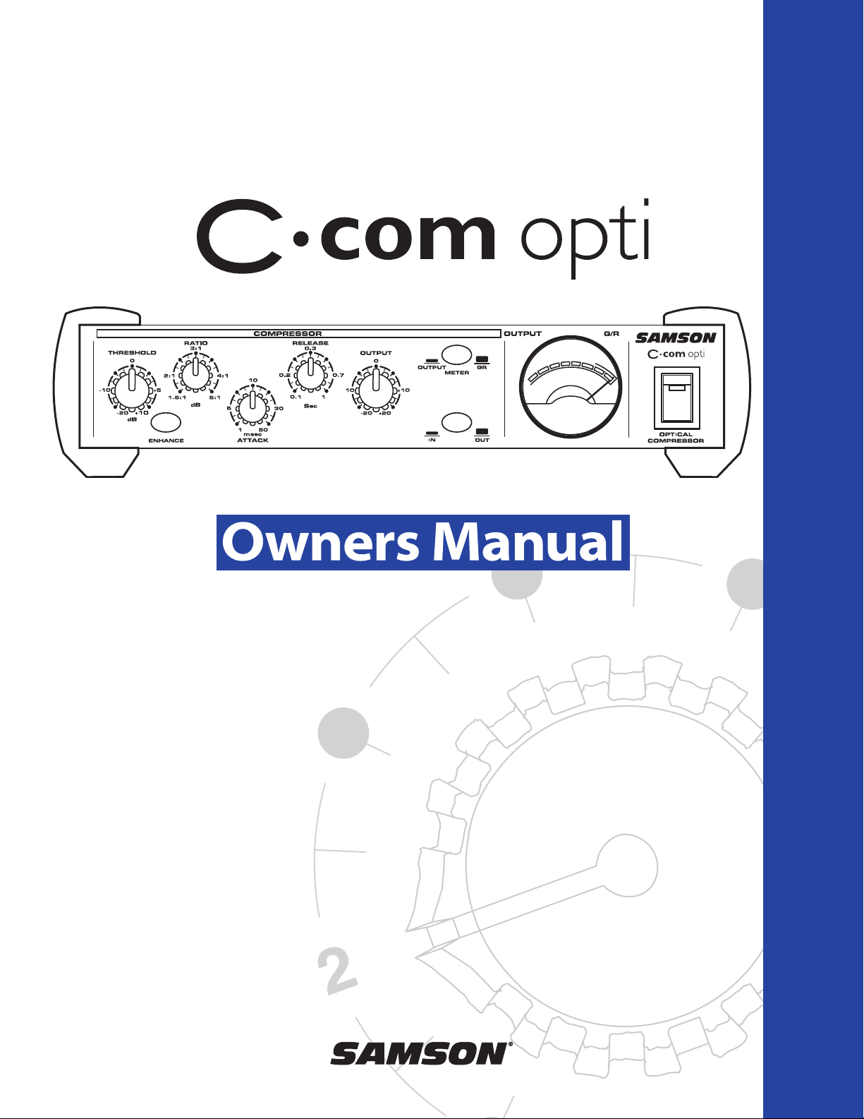
Samson C-com opti Owner`s Manual
SAMSON
+4
0
-3
-2
-1
-5
-7
-10
-20
VU
C Class Signal Processors
OPTICAL COMPRESSOR
AUDIO
Safety Instructions
Caution: To reduce the hazard of electrical
shock, do not remove cover or back.
No user serviceable parts inside. Please refer all
servicing to qualified personnel.
WARNING: To reduce the risk of fire or electric shock, do not expose this unit to rain or moisture.
The lightning flash with an arrowhead symbol within an equilateral triangle, is intended to alert the user to the
presence of uninsulated "dangerous voltage" within the products enclosure that may be of sufficient magnitude to
constitute a risk of electric shock to persons.
The exclamation point within an equilateral triangle is intended to alert the user to the presence of important operating and maintenance (servicing) instructions in the literature accompanying the product.
Important Safety Instructions
1. Please read all instructions before operating the unit.
2. Keep these instructions for future reference.
3. Please heed all safety warnings.
4. Follow manufacturers instructions.
5. Do not use this unit near water or moisture.
6. Clean only with a damp cloth.
7. Do not block any of the ventilation openings. Install in accordance with the manufacturers instructions.
8. Do not install near any heat sources such as radiators, heat registers, stoves, or other apparatus
(including amplifiers) that produce heat.
9. Do not defeat the safety purpose of the polarized or grounding-type plug. A polarized plug has two
blades with one wider than the other. A grounding type plug has two blades and a third grounding
prong. The wide blade or third prong is provided for your safety. When the provided plug does not fit
your outlet, consult an electrician for replacement of the obsolete outlet.
10. Protect the power cord from being walked on and pinched particularly at plugs, convenience receptacles and at the point at which they exit from the unit.
11. Unplug this unit during lightning storms or when unused for long periods of time.
12. Refer all servicing to qualified personnel. Servicing is required when the unit has been damaged in any
way, such as power supply cord or plug damage, or if liquid has been spilled or objects have fallen into
the unit, the unit has been exposed to rain or moisture, does not operate normally, or has been
dropped.

Table of Contents
Introduction 4
C com opti Features 5
Controls and Functions
Front Panel Layout 6
Rear Panel Layout 6
Operating the C com opti
Setting Up the C com opti 7
Compressing A Signal 8
Using the Enhancer 9
System Set-ups 10
Dynamics Processing 101 11
Applications 12
C com opti Connections 13
Stacking and Installing the Tilting Feet 14
Installing the Optional CRK1 Dual Rack adapter 15
Specifications 16
C com opti Block Diagram 17
Copyright 2003, Samson Technologies Corp.
Printed June, 2003
Samson Technologies Corp.
575 Underhill Blvd.
P.O. Box 9031
Syosset, NY 11791-9031
Phone: 1-800-3-SAMSON (1-800-372-6766)
Fax: 516-364-3888
www.samsontech.com

4
Congratulations on purchasing the C com opti, optical compressor by Samson Audio! The C com
opti is a compact, high-quality device that provides extensive dynamics processing with a classic and
musical response and with the warm sound that only a photo cell compressor can offer. Easy operation makes the C com opti the perfect solution for dynamics processing in live sound and in recording applications for tracking, mixing and mastering. Whether you use a small amount of compression
to control level, or a drastic amount of compression for a intense retro effect, the C com opti will
delive rthe contrl and emotion. And for you tweekazoids, there is full manual control with variable
Threshold, Ratio, Attack and Release parameters. In addition, the C com opti offers a powerful
ENHANCE circuit, which when engaged, adds a pleasant restoration of the high frequencies that can
sometimes be diminished during heavy gain reduction. To help you monitor and set the best levels,
the C com opti features an easy-to-read, back-lit, analog VU meter which can be switched to display
Output Level or Gain Reduction. For stereo operation, two C com opti’s can be joined together using
the LINK input allowing the two units to operate as one stereo device. Like all Samson Audio C class
processors, the C com opti can be stacked on other C class models, and can be set-up on an angle
using the included tilting feet. The C com opti is also a half-single rack space unit and can be rack
mounted using the Samson CRK1. Most importantly, by providing transparent gain control and
superb audio fidelity, the C com opti’s signal path will impress the most critical listeners.
Although this unit is designed for easy operation, we suggest you take some time out first to go
through these pages so you can fully understand how we’ve implemented a number of unique features. In this manual, you’ll find a more detailed description of the features of the C com opti, as well
as a guided tour through the front and rear panels, step-by-step instructions for using the C com opti
and full specifications. You’ll also find a warranty card enclosed—please don’t forget to fill it out and
mail it so that you can receive online technical support and so we can send you updated information
about other Samson products in the future.
With proper care and adequate air circulation, your C com opti will operate trouble free for many
years. We recommend you record your serial number in the space provided below for future reference.
Serial number:
Date of purchase:
Should your unit ever require servicing, a Return Authorization number (RA) must be obtained
before shipping your unit to Samson. Without this number, the unit will not be accepted. Please call
Samson at 1-800-3SAMSON (1-800-372-6766) for a Return Authorization number prior to shipping
your unit. Please retain the original packing materials and if possible, return the unit in the original
carton and packing materials.
Introduction
5
C com opti Features
The Samson C com opti optical compressor utilizes a unique photo cell design which produces a classic sound while han-
dling the job of gain management . Here are some of its main features:
• Full featured, optical compressor dynamics processor ideal for live sound and recording.
• Unique photo gain cell design offering classic, musical response while controling signal levels.
• Variable control of THRESHOLD, RATIO, ATTACK, RELEASE and OUTPUT.
• Large analog, back-lit VU Meter that can be switched to display either Output Level or Gain Reduction.
• Enhancer circuit to help restore high frequencies that are sometimes lost as a result of heavy gain
reduction.
• STEREO LINK INPUT, 1/4-inch phone connector for using two C com opti’s for processing stereo sig-
nals.
• High quality variable resistors provide smooth control over the various adjustable parameters.
• Easy to read and operate LED, backlit, push switches for BYPASS, ENHANCE and METER.
• Capable of handling +4dBu and –10dBV signals.
• Advanced electronics incorporating high quality photo cell and low noise op-amps, providing a trans-
parent signal path.
• Oversized, rubber bumpers with tilting feet allow several Samson C class units to be stacked and tilted
in an ergonomically correct operating position.
• The stylish bead blasted electric blue anodized front-panel is as easy to read as it is to look at.
• Three-year extended warranty.
-3
-2
-5
-1
-7
-10
-20
SAMSON
0
+4
VU
6
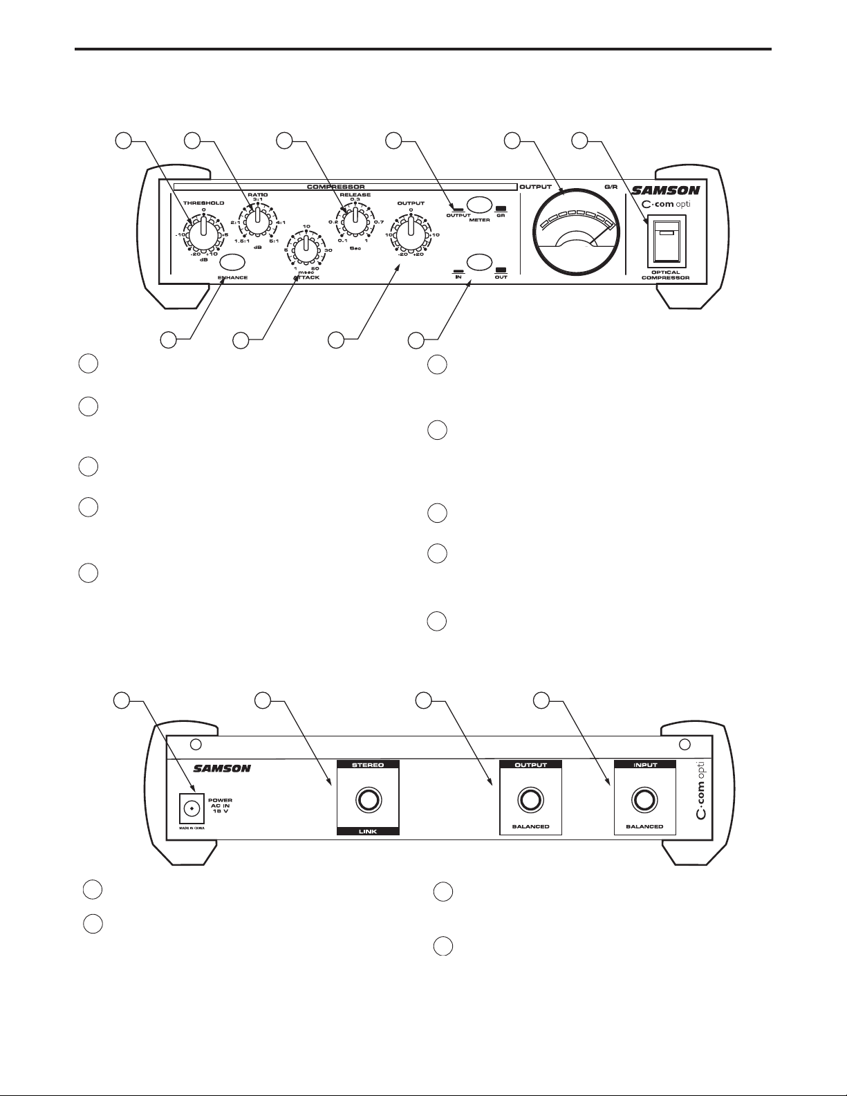
C com opti Layout
AACINLET - AC Power Supply Connector.
B STEREO LINK INPUT- 1/4” TRS Connector for
linking two C com opti’s together for stereo
operation.
C 1/4” TRS OUTPUT - 1/4” TRS connector for
Balanced line OUTPUT.
D 1/4” TRS INPUT - 1/4” TRS connector for
Balanced line INPUT.
1 THRESHOLD - Used to set the minimum signal level
at which the compressor circuit begins to function.
2 RATIO - Controls the amount of gain reduction in
proportion to the amount of signal over the selected threshold level.
3 RELEASE - Adjusts the length of time the compres-
sor takes to return the signal to it’s original level.
4 METER SWITCH - When pressed in, the METER
shows OUTPUT level and in the out position the
METER shows GAIN REDUCTION.
5 VU METER - Back-lit, analog VU meter which,
depending on the METER switch, displays the
amount of Gain Reduction or Output Level.
6 MAINS POWER SWITCH - When pressed on,
the green LED lights indicating that the C com
opti is powered up and ready for operation.
7 ENHANCE SWITCH - Used to engage the C
com opti’s Enhance circuit restoring the high
end loss resulting from extreme Gain
Reduction.
8 ATTACK - Adjusts the amount of time the com-
pressor takes to reach full gain reduction.
9 OUTPUT - Controls the overall level, and is
used for “make-up” gain to restore the signal
back to its original level after the compression.
10 BYPASS SWITCH- When pressed in, the green
LED lights indicating that the C com opti’s compression circuit is active.
Rear Panel Layout
Front Panel Layout
12 3 4 56
78 9 10
-3
-2
-5
-1
-7
-10
-20
SAMSON
0
+4
VU
A
B
C
D
 Loading...