

Page 1
SAMSON
+4
0
-3
-2
-1
-5
-7
-10
-20
VU
C Class Signal Processors
OPTICAL COMPRESSOR
AUDIO
Page 2
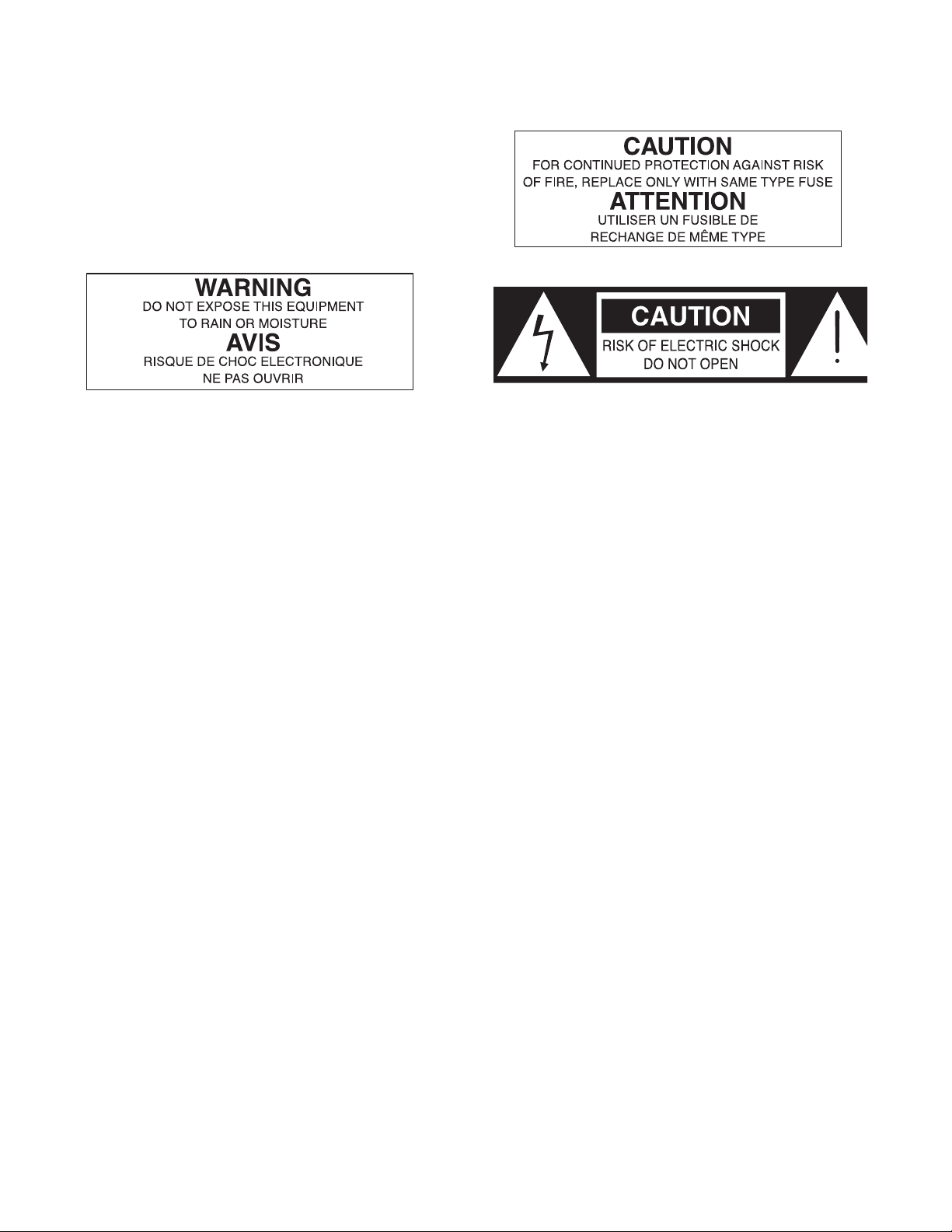
Safety Instructions
Caution: To reduce the hazard of electrical
shock, do not remove cover or back.
No user serviceable parts inside. Please refer all
servicing to qualified personnel.
WARNING: To reduce the risk of fire or electric shock, do not expose this unit to rain or moisture.
The lightning flash with an arrowhead symbol within an equilateral triangle, is intended to alert the user to the
presence of uninsulated "dangerous voltage" within the products enclosure that may be of sufficient magnitude to
constitute a risk of electric shock to persons.
The exclamation point within an equilateral triangle is intended to alert the user to the presence of important operating and maintenance (servicing) instructions in the literature accompanying the product.
Important Safety Instructions
1. Please read all instructions before operating the unit.
2. Keep these instructions for future reference.
3. Please heed all safety warnings.
4. Follow manufacturers instructions.
5. Do not use this unit near water or moisture.
6. Clean only with a damp cloth.
7. Do not block any of the ventilation openings. Install in accordance with the manufacturers instructions.
8. Do not install near any heat sources such as radiators, heat registers, stoves, or other apparatus
(including amplifiers) that produce heat.
9. Do not defeat the safety purpose of the polarized or grounding-type plug. A polarized plug has two
blades with one wider than the other. A grounding type plug has two blades and a third grounding
prong. The wide blade or third prong is provided for your safety. When the provided plug does not fit
your outlet, consult an electrician for replacement of the obsolete outlet.
10. Protect the power cord from being walked on and pinched particularly at plugs, convenience receptacles and at the point at which they exit from the unit.
11. Unplug this unit during lightning storms or when unused for long periods of time.
12. Refer all servicing to qualified personnel. Servicing is required when the unit has been damaged in any
way, such as power supply cord or plug damage, or if liquid has been spilled or objects have fallen into
the unit, the unit has been exposed to rain or moisture, does not operate normally, or has been
dropped.
Page 3

Table of Contents
Introduction 4
C com opti Features 5
Controls and Functions
Front Panel Layout 6
Rear Panel Layout 6
Operating the C com opti
Setting Up the C com opti 7
Compressing A Signal 8
Using the Enhancer 9
System Set-ups 10
Dynamics Processing 101 11
Applications 12
C com opti Connections 13
Stacking and Installing the Tilting Feet 14
Installing the Optional CRK1 Dual Rack adapter 15
Specifications 16
C com opti Block Diagram 17
Copyright 2003, Samson Technologies Corp.
Printed June, 2003
Samson Technologies Corp.
575 Underhill Blvd.
P.O. Box 9031
Syosset, NY 11791-9031
Phone: 1-800-3-SAMSON (1-800-372-6766)
Fax: 516-364-3888
www.samsontech.com
Page 4

4
Congratulations on purchasing the C com opti, optical compressor by Samson Audio! The C com
opti is a compact, high-quality device that provides extensive dynamics processing with a classic and
musical response and with the warm sound that only a photo cell compressor can offer. Easy operation makes the C com opti the perfect solution for dynamics processing in live sound and in recording applications for tracking, mixing and mastering. Whether you use a small amount of compression
to control level, or a drastic amount of compression for a intense retro effect, the C com opti will
delive rthe contrl and emotion. And for you tweekazoids, there is full manual control with variable
Threshold, Ratio, Attack and Release parameters. In addition, the C com opti offers a powerful
ENHANCE circuit, which when engaged, adds a pleasant restoration of the high frequencies that can
sometimes be diminished during heavy gain reduction. To help you monitor and set the best levels,
the C com opti features an easy-to-read, back-lit, analog VU meter which can be switched to display
Output Level or Gain Reduction. For stereo operation, two C com opti’s can be joined together using
the LINK input allowing the two units to operate as one stereo device. Like all Samson Audio C class
processors, the C com opti can be stacked on other C class models, and can be set-up on an angle
using the included tilting feet. The C com opti is also a half-single rack space unit and can be rack
mounted using the Samson CRK1. Most importantly, by providing transparent gain control and
superb audio fidelity, the C com opti’s signal path will impress the most critical listeners.
Although this unit is designed for easy operation, we suggest you take some time out first to go
through these pages so you can fully understand how we’ve implemented a number of unique features. In this manual, you’ll find a more detailed description of the features of the C com opti, as well
as a guided tour through the front and rear panels, step-by-step instructions for using the C com opti
and full specifications. You’ll also find a warranty card enclosed—please don’t forget to fill it out and
mail it so that you can receive online technical support and so we can send you updated information
about other Samson products in the future.
With proper care and adequate air circulation, your C com opti will operate trouble free for many
years. We recommend you record your serial number in the space provided below for future reference.
Serial number:
Date of purchase:
Should your unit ever require servicing, a Return Authorization number (RA) must be obtained
before shipping your unit to Samson. Without this number, the unit will not be accepted. Please call
Samson at 1-800-3SAMSON (1-800-372-6766) for a Return Authorization number prior to shipping
your unit. Please retain the original packing materials and if possible, return the unit in the original
carton and packing materials.
Introduction
Page 5

5
C com opti Features
The Samson C com opti optical compressor utilizes a unique photo cell design which produces a classic sound while han-
dling the job of gain management . Here are some of its main features:
• Full featured, optical compressor dynamics processor ideal for live sound and recording.
• Unique photo gain cell design offering classic, musical response while controling signal levels.
• Variable control of THRESHOLD, RATIO, ATTACK, RELEASE and OUTPUT.
• Large analog, back-lit VU Meter that can be switched to display either Output Level or Gain Reduction.
• Enhancer circuit to help restore high frequencies that are sometimes lost as a result of heavy gain
reduction.
• STEREO LINK INPUT, 1/4-inch phone connector for using two C com opti’s for processing stereo sig-
nals.
• High quality variable resistors provide smooth control over the various adjustable parameters.
• Easy to read and operate LED, backlit, push switches for BYPASS, ENHANCE and METER.
• Capable of handling +4dBu and –10dBV signals.
• Advanced electronics incorporating high quality photo cell and low noise op-amps, providing a trans-
parent signal path.
• Oversized, rubber bumpers with tilting feet allow several Samson C class units to be stacked and tilted
in an ergonomically correct operating position.
• The stylish bead blasted electric blue anodized front-panel is as easy to read as it is to look at.
• Three-year extended warranty.
-3
-2
-5
-1
-7
-10
-20
SAMSON
0
+4
VU
Page 6

6
C com opti Layout
AACINLET - AC Power Supply Connector.
B STEREO LINK INPUT- 1/4” TRS Connector for
linking two C com opti’s together for stereo
operation.
C 1/4” TRS OUTPUT - 1/4” TRS connector for
Balanced line OUTPUT.
D 1/4” TRS INPUT - 1/4” TRS connector for
Balanced line INPUT.
1 THRESHOLD - Used to set the minimum signal level
at which the compressor circuit begins to function.
2 RATIO - Controls the amount of gain reduction in
proportion to the amount of signal over the selected threshold level.
3 RELEASE - Adjusts the length of time the compres-
sor takes to return the signal to it’s original level.
4 METER SWITCH - When pressed in, the METER
shows OUTPUT level and in the out position the
METER shows GAIN REDUCTION.
5 VU METER - Back-lit, analog VU meter which,
depending on the METER switch, displays the
amount of Gain Reduction or Output Level.
6 MAINS POWER SWITCH - When pressed on,
the green LED lights indicating that the C com
opti is powered up and ready for operation.
7 ENHANCE SWITCH - Used to engage the C
com opti’s Enhance circuit restoring the high
end loss resulting from extreme Gain
Reduction.
8 ATTACK - Adjusts the amount of time the com-
pressor takes to reach full gain reduction.
9 OUTPUT - Controls the overall level, and is
used for “make-up” gain to restore the signal
back to its original level after the compression.
10 BYPASS SWITCH- When pressed in, the green
LED lights indicating that the C com opti’s compression circuit is active.
Rear Panel Layout
Front Panel Layout
12 3 4 56
78 9 10
-3
-2
-5
-1
-7
-10
-20
SAMSON
0
+4
VU
A
B
C
D
Page 7

7
Operating The C com opti
SETTING UP THE C com opti
Setting up your C com opti is a simple procedure, which takes only a few minutes. There are many ways to interface the C com opti with various recording or live sound set-ups, so take some time to decide which audio
devices you want to connect. The following section shows a simple set-up for a recording situation with a C com
opti connected to a mixer’s insert points to compress an individual track, in this case a lead vocal.
Remove all packing materials (save them in case of need for future service) and plug the provided AC adapter in
to the rear AC power inlet, but don’t plug the power pack into a wall outlet just yet. You can use the C com opti in
line with the output of a mixer or recorder, or in a send and return insert-point which is typically found on input
and output channels of mid to larger mixers. For detailed wiring diagrams see page 13 of this manual.
Follow the next few steps described in the section below to begin to use your C com opti.
• Using standard 1/4-inch insert cables, connect the mixer’s SEND to the to the C com 16’s INPUT and the
mixer’s RETURN to the C com opti’s OUTPUT.
• Plug the C com opti power pack into a wall outlet and switch the unit on by pressing the power switch.
• Next, turn on your mixer and monitor system, but keep the listening level low until you become more
familiar with your new processor.
• Set the controls to the following default positions:
COMPRESSOR THRESHOLD +10dBu (fully clockwise)
ENHANCER SWITCH OUT (YELLOW LED OFF)
RATIO 1.5 : 1 (fully counter-clockwise)
AT TACK 1 msec (fully counter-clockwise)
RELEASE 1 sec (fully clockwise)
METER SWITCH IN (YELLOW LED ON)
OUTPUT LEVEL O dBu
BY PASS OUT (GREEN LED OFF)
-3
-2
-5
SAMSON
-1
0
+4
VU
-7
-10
-20
Page 8

8
COMPRESSING A SIGNAL
C com opti’s compressor section can be used for a variety of gain management
tasks including printing signals to a multi-track recorder, as a mix-down effect,
mastering, and for increasing the loudness of a live PA system. To begin compressing your signal, follow the steps below:
• Follow the section above, “SETTING UP THE C com opti” for normalizing
the controls.
• Press the BYPASS switch to the IN position.
• Run a signal into your mixer, in this case a vocal track, and raise the input
fader until you see the C com opti’s OUTPUT METER read about 0dB.
• Engage the C com opti by pressing the BYPASS switch so that the
GREEN LED turns on.
• Now press the METER switch to the out position so that the LED goes off,
allowing you to monitor the GAIN REDUCTION. The meter should still
read about 0dB.
Note: In this default configuration, the C com opti is simply passing audio
at unity gain with no dynamics processing. It’s a good idea to check your
gain structure at this point. Use the BYPASS switch and the METER to
match the level.
• Once you have set a good gain structure you can begin to compress your
signal.
• Press the BYPASS switch to the IN position so that the green LED is on.
• Adjust the Ratio to 3:1, the ATTACK to 5 and the RELEASE control to 0.3.
• Now, gradually lower the THRESHOLD level and listen for the compression. For a visual representation, the amount of compression is indicated
on the GAIN REDUCTION meter. Try to get the GAIN REDUCTION
METER to read between -1 and -3 dB.
Now, you can experiment with lowering the THRESHOLD a bit and raising
the OUTPUT level some. By lowering the THRESHOLD level you are
adding more compression, so the level may drop. Use the OUTPUT level
control for “make-up gain”, getting back to unity gain (the same level), with
the BYPASS in or out.
• Once you get a feel for squeezing the signal, you can experiment with the
ATTACK and RELEASE controls.
As always, experience is the best teacher, so plug in and get experience! Try your compressor
on different audio signals. You’ll find it useful and pleasant sounding on a variety of applications. For more information on dynamics and their application see the sections “Dynamic
Processing 101” and “Applications” later in this manual.
Operating The C com opti
Page 9

9
Operating The C com opti
USING THE ENHANCER
The C com opti’s ENHANCER switch can be engaged to activate the EFR (Enhanced Frequency Recovery) circuit. By engaging the ENHANCER, the C com opti EFR
restores the high frequency content that can be lost when
high gain reduction is applied. The C com opti EFR
achieves this by adding back the high-end of the original
signal in an amount that is equal to the amount of gain
reduction.
• Follow the section above, “SETTING UP THE C
com opti” for normalizing the controls and run a
signal such as a vocal track through the C com
opti plus.
• Press the BYPASS switch to the IN position.
• Set the ATTACK control to 5 and the RELEASE
control to 0.3.
• Adjust the Ratio to 4 - 5:1.
• Press the ENHANCER switch and listen to how the high end is restored.
USING THE STEREO LINK
For stereo applications, two C com opti’s can be used in together using the rear
panel STEREO LINK connector. The STEREO LINK connector is a 1/4-inch phone
jack that provides external access to the C com opti compression detection circuit.
When using two C com opti’s in stereo applications, it’s important that the relative
balance between the left and right channels is maintained. By connecting a standard, 1/4-inch instrument cable between the STEREO LINK connector of the left
channel C com opti and the STEREO LINK connector on the right channel C com
opti, the two compressor’s detection circuits are internally summed together. The
result is, both the left and right channels signals will work together to effect the
amount compression on both the left and right channels. Now, that the two C com
opti’s are responding to the same detection signal, you should set the controls of
the left and right channels C com opti to the same positions, since each C com
opti’s THRESHOLD, ENHANCE, ATTACK, RATIO, RELEASE and OUTPUT controls are still working independently.
Page 10

10
C com opti System Set-Ups
INSERT POINT COMPRESSION
In this example, two C com opti’s are used individually to compress the signal of the bass and keyboard tracks. The C com
opti’s are connected to the mixer’s insert points using a standard 1/4-inch insert “Y” cable. See page 13 for a detailed wiring
diagram.
LIVE SOUND SYSTEM WITH STEREO COMPRESSION
In this example, two C com opti’s are connected, “in-line” between the mixer and the powered speakers, thereby compressing the full range signal from the mixer. The STEREO LINK on both units are connected together using a standard 1/4-inch
instrument cable.
-3
-2
-5
-1
-7
0
-10
-20
+4
VU
SAMSON
-3
-2
-5
-1
-7
0
-10
-20
+4
VU
SAMSON
C com opti
-3
-2
-5
-1
-7
0
-10
-20
+4
VU
SAMSON
-3
-2
-5
-1
-7
0
-10
-20
+4
VU
SAMSON
C com opti
 Loading...