

Page 1

Controller with Electric Actuator
Type 5757-7
Fig. 1 · Type 5757-7 Controller with Electric Actuator for heating applications
Mounting and
Operating Instructions
EB 5757-7 EN
Firmware version 1.0x
Edition August 2005
Page 2

Contents
Contents Page
1 Design and principle of operation . . . . . . . . . . . . . . . . . . . 5
1.1 Accessories . . . . . . . . . . . . . . . . . . . . . . . . . . . . . . 6
1.2 Technical data . . . . . . . . . . . . . . . . . . . . . . . . . . . . . 6
2 Connection to the valve . . . . . . . . . . . . . . . . . . . . . . . . 7
2.1 Mounting position . . . . . . . . . . . . . . . . . . . . . . . . . . . 7
3 Electrical connection . . . . . . . . . . . . . . . . . . . . . . . . . . 8
4 Dimensions in mm . . . . . . . . . . . . . . . . . . . . . . . . . . 11
5 Functions . . . . . . . . . . . . . . . . . . . . . . . . . . . . . . . 13
5.1 Outdoor temperature compensated control . . . . . . . . . . . . . . . 13
5.1.1 Override using potentiometer . . . . . . . . . . . . . . . . . . . . . 15
5.1.2 Summer mode . . . . . . . . . . . . . . . . . . . . . . . . . . . . 15
5.1.3 Delayed outdoor temperature adaptation. . . . . . . . . . . . . . . . 16
5.2 Fixed set point control . . . . . . . . . . . . . . . . . . . . . . . . . 16
5.2.1 Room temperature influence . . . . . . . . . . . . . . . . . . . . . . 16
5.3 Operating modes . . . . . . . . . . . . . . . . . . . . . . . . . . . 18
5.3.1 Switchover via binary input . . . . . . . . . . . . . . . . . . . . . . 18
5.3.2 Switchover via room panel . . . . . . . . . . . . . . . . . . . . . . 19
5.3.3 Switchover via binary input in room panel . . . . . . . . . . . . . . . 19
5.4 Frost protection . . . . . . . . . . . . . . . . . . . . . . . . . . . . 19
5.5 Return flow temperature limitation . . . . . . . . . . . . . . . . . . . 19
5.6 Pump forced operation . . . . . . . . . . . . . . . . . . . . . . . . 20
5.7 External request for heat demand . . . . . . . . . . . . . . . . . . . 20
5.8 Control principle . . . . . . . . . . . . . . . . . . . . . . . . . . . 21
5.9 Direction of action. . . . . . . . . . . . . . . . . . . . . . . . . . . 21
6 Configuration and operation using TROVIS-VIEW interface . . . . . . 23
6.1 General . . . . . . . . . . . . . . . . . . . . . . . . . . . . . . . 23
6.1.1 System requirements . . . . . . . . . . . . . . . . . . . . . . . . . 23
6.2 Installing TROVIS-VIEW software . . . . . . . . . . . . . . . . . . . 24
6.3 Starting TROVIS-VIEW and performing settings . . . . . . . . . . . . 25
6.3.1 Activating/deactivating functions . . . . . . . . . . . . . . . . . . . 27
6.3.2 Setting parameters . . . . . . . . . . . . . . . . . . . . . . . . . . 28
6.3.3 Reading operational information. . . . . . . . . . . . . . . . . . . . 29
7 Data transmission. . . . . . . . . . . . . . . . . . . . . . . . . . . 31
7.1 Data transmission between TROVIS-VIEW and the actuator
(connecting cable). . . . . . . . . . . . . . . . . . . . . . . . . . . 32
7.1.1 Offline operation (indirect data transmission) . . . . . . . . . . . . . . 33
2 EB 5757-7 EN
Page 3

Contents
7.1.2 Online operation (direct data transmission). . . . . . . . . . . . . . . 33
7.2 SAMSON memory pen . . . . . . . . . . . . . . . . . . . . . . . . 34
7.2.1 Data transfer between TROVIS-VIEW and memory pen . . . . . . . . . 34
7.2.2 Data transmission between actuator and memory pen. . . . . . . . . . 35
7.2.3 Copy function. . . . . . . . . . . . . . . . . . . . . . . . . . . . . 37
7.2.4 Manual operation . . . . . . . . . . . . . . . . . . . . . . . . . . . 37
8 Appendix. . . . . . . . . . . . . . . . . . . . . . . . . . . . . . . 38
8.1 Function block list . . . . . . . . . . . . . . . . . . . . . . . . . . . 38
8.2 Parameter list . . . . . . . . . . . . . . . . . . . . . . . . . . . . . 39
8.3 Customer settings . . . . . . . . . . . . . . . . . . . . . . . . . . . 40
EB 5757-7 EN 3
Page 4

Safety instructions
General safety instructions
4
4
4
4
4
Assembly, start-up and operation of this device may only be performed by
trained and experienced personnel familiar with the product.
According to these mounting and operating instructions, trained personnel
refers to individuals who are able to judge the work they are assigned to
and recognize possible hazards due to their specialized training, their
knowledge and experience as well as their knowledge of the applicable
standards.
Any hazards which could be caused in the connected valve by the process
medium, operating pressure or moving parts are to be prevented by means
of the appropriate measures.
Proper transportation and storage are assumed.
The actuators has been designed for use in electrical power installations.
For wiring and maintenance, you are required to observe the relevant safety
regulations. The actuator must be protected against unintentional
reconnection of the power supply.
Note:
Actuators with a CE marking fulfill the requirements of the Directives
94/9/EC and 89/336/EEC.
The Declaration of Conformity is available on request.
4 EB 5757-7 EN
Page 5
Design and principle of operation
1 Design and principle of
operation
The Type 5757-7 consists of a digital con
troller integrated into the housing of an elec
tric actuator.
The combination is especially designed for
heating applications as well as for fixed set
point control of heating systems in small to
medium-sized buildings. It is particularly
suitable for mounting to SAMSON
Type 3222, Type 3222 N, Type 2488 and
Type 3267 Valves (DN 15 to 25) and to
special versions of Type 3226 and
Type 3260 Valves.
The digital controller is connected to a flow
sensor on the input side, which can be optionally upgraded by a return flow, outdoor
or room sensor.
In addition to the Pt 1000 input, the digital
controller has a potentiometer input (1000
to 1100Ωor 1000 to 2000Ω) to measure
the flow temperature. This input influences
the heating characteristic in the case of outdoor temperature compensated control and
the room temperature set point in the case of
fixed set point control with room tempera
ture influence.
Heating characteristic and set point parame
ters can be changed over the TROVIS-VIEW
Operator Interface.
The output signal of the integrated digital
controller is applied as a three-point step
ping signal to the synchronous motor of the
actuator. The signal is transferred over the
connected gear to the actuator stem (3) and
used as the positioning force.
The motor is switched off by torque-depend
ent switches when an end position is
reached or in case the motor is overloaded.
-
-
-
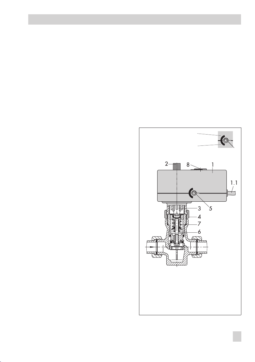
The actuator is mounted onto the valve using
a coupling nut (4).
When the actuator stem extends, the valve is
closed, opposing the force of the valve
spring (7). When the actuator stem retracts,
the valve is opened as the plug stem (6) fol
lows the motion of the return spring.
The valve can be moved to any position
when the power supply is disconnected by
the handwheel (2). Travel and direction of
action can be read off the travel indicator
(5) on the side of the actuator housing.
Stem retracts
Stem extends
-
1 Controller/actuator
1.1 Connecting lead
2 Handwheel (only to
be used when power
is disconnected)
3 Actuator stem
-
Fig. 2 · Functional diagram
4 Coupling nut
5 Travel indicator
6 Plug stem
7 Valve spring
8 Cover, serial
interface connection
-
5
EB 5757-7 EN 5
Page 6

Design and principle of operation
1.1 Accessories
Heating applications, see section 5
Type 5267-2 Pt 1000 Contact Sensor
4
Permissible temperatures:
Medium –20 to 120 °C
Ambient –20 to 120 °C
Degree of protection IP 42
Type 5257-2 Pt 1000 Room Sensor
4
with potentiometer (remote adjuster)
Permissible temperatures:
Medium –35 to 70 °C
Ambient –35 to 70 °C
Degree of protection IP 20
Type 5257-7 Room Panel with
4
potentiometer and mode selector switch
Permissible temperatures:
Medium –20 to 60 °C
Ambient –20 to 60 °C
Degree of protection IP 30
Type 5227-2 Pt 1000 Outdoor Sensor
4
Permissible temperatures:
Medium –35 to 85 °C
Ambient –35 to 85 °C
Degree of protection IP 44
Communication, refer to section 6
TROVIS-VIEW Configuration and Opera
4
tor Interface (6661-1066) for
Type 5757-7 Controller with Electric Actu
ator
Hardware package
4
Accessories for direct and indirect data
transmission (including a memory pen,
connecting cable and modular adapter),
order no. 1400-7704
Memory pen
4
Indirect data transmission,
order no. 1400-7697
1.2 Technical data
Type 5757-7 Controller with Electric Actuator
Temperature sensor Max. 3 x Pt 1000
Setting range 0 to 150 °C
Potentiometer input 1000 to 1100Ωor
Binary output 230 V/50 Hz/1 A
Rated travel 6 mm
Transit time for
rated travel
Nominal thrust 300 N
Supply voltage 230 V (±10 %) / 50 Hz
Power consumption Approx. 3 VA
Permissible temperatures
Ambient 0 to 50 °C
Storage –20 to 70 °C
Degree of protection IP 42
Mounting position Any, but not suspended
Noise immunity EN 61000-6-2
-
Noise emission EN 61000-6-3
-
Weight Approx. 0.7 kg
1000 to 2000
Circulation pump or
external heat demand
20 s
Ω
6 EB 5757-7 EN
Page 7
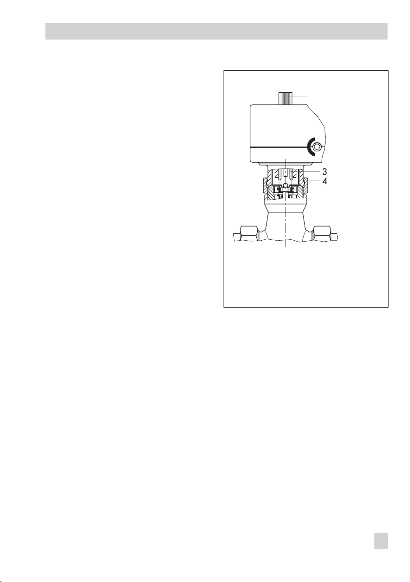
2 Connection to the valve
The actuator has a force-locking connection
to the valve in de-energized state.
Turn the handwheel (2) counterclockwise
4
to retract the actuator stem as far as it
will go.
Place the actuator on the valve connec
4
tion and screw coupling nut (4) tight
(tightening torque 20 Nm).
2.1 Mounting position
Connection to the valve
2
-
Any mounting position may be used, how
ever, may not be installed in a suspended
position.
-
2 Handwheel
3 Actuator stem
4 Coupling nut
Fig. 3 · Connecting actuator and valve
EB 5757-7 EN 7
Page 8

Electrical connection
3 Electrical connection
When installing electric lines, you
are required to observe the regula
tions governing electrical power
plant installation according to
DIN VDE 0100 as well as the regu
lations of your local power supply
company.
Use a suitable power supply which
guarantees that no dangerous volt
ages reach the device in standard
operation or in case of a fault in the
system or any other system parts.
The controller with electric actuator requires
a Pt 1000 temperature sensor (e.g. Type
5267-2) to be connected to measure the
flow temperature.
Depending on the control task, an outdoor
sensor (e.g. Type 5227-2) or a room sensor
(e.g. Type 5257-2) or a room panel
(Type 5257-7 only) can be connected. Combining one of these sensors with a return
flow sensor (e.g. Type 5267-2) is usually
possible.
Additionally, the controller with electric ac
tuator has a potentiometer input 1000 to
1100Ω(e.g. Type 5257-7) or 1000 to
2000Ω(e.g. Type 5257-2). This input is
used to correct the room set point (±5 K) in
case of fixed set point control with room
temperature influence (see section 5.2). On
using an outdoor sensor, it can change the
adjusted heating characteristic (see sec
tion 5.1).
The non-floating pump output can alterna
tively be used as an binary output for an ex
ternal request for heat demand.
-
-
-
-
-
-
The connected sensors are monitored for
line breakages.
A fault in the line of a sensor is indicated by
the red LED blinking slowly.
Caution!
Connect the actuator to the electrical
network only after the power supply
has first been switched off. Make
sure the power cannot be switched
on unintentionally!
The pump output L’ is non-floating
(230 V~).
Perform the electrical connection de-
4
pending on the heating application according to one of the following wiring diagrams (Figs. 4 and 5).
As soon as the actuator is connected to
the power supply, the initialization procedure starts.
The actuator stem extends (with operating direction selected for globe valves)
and the red and yellow LEDs are illumi
nated located under the cover on top of
the actuator.
As soon as the actuator stem has
reached the final position, the red LED is
turned off. The yellow LED remains illu
minated and indicates that the controller
with electric actuator is ready for opera
tion.
-
-
-
-
8 EB 5757-7 EN
Page 9
Electrical connection
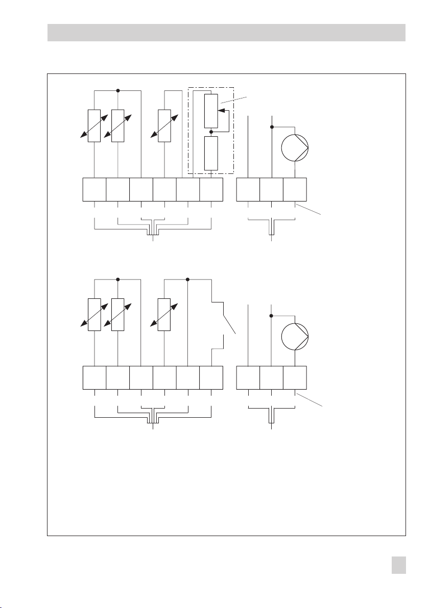
VS
Pt 1000
Pt 1000
ASRüS
Pt 1000
100/
1000 Ω
1000 Ω
230 V,
50 Hz
34 6521LL´N
or ye rd br blk gr br bl blk
Application with flow, return flow, and outdoor sensors as well as potentiometer
to adjust the set point
e.g. Type 5257-2 with remote adjuster
VS
Pt 1000
Pt 1000
ASRüS
Pt 1000
230 V,
50 Hz
34 6521LL´N
Caution!
Live wires
or ye rd br blk gr br bl blk
Application with flow, return flow, and outdoor sensors as well as binary input
to switch between operating modes
or orange
ye yellow
rd red
br brown
blk black
gr green
Fig. 4 · Wiring diagrams Note:
Caution!
Live wires
br brown
bl blue
blk black
Terminals at point of installation, not included in scope of delivery
EB 5757-7 EN 9
Page 10
Electrical connection
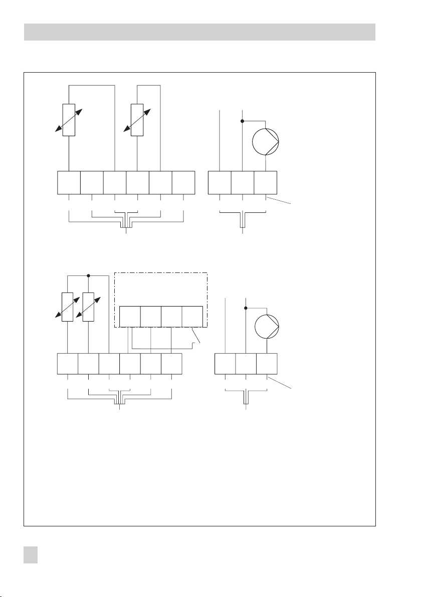
VS
Pt 1000
AS
230 V, 50 Hz
Pt 1000
34 6521LL´N
or ye rd br blk gr br bl blk
Application with flow sensor and outdoor sensors
VS
RüS
Pt 1000
Pt 1000
34 65
21LL´N
or ye rd br blk gr br bl blk
Type 5257-7
Room Panel
1432
230 V, 50 Hz
Caution!
Live wires
Caution!
Live wires
Application with flow, return flow, and room sensors with mode selector switch and set point adjuster
or orange
ye yellow
rd red
Fig.5·Wiring diagrams Note:
br brown
blk black
gr green
br brown
bl blue
blk black
Terminals at point of installation, not included in scope of delivery
10 EB 5757-7 EN
Page 11
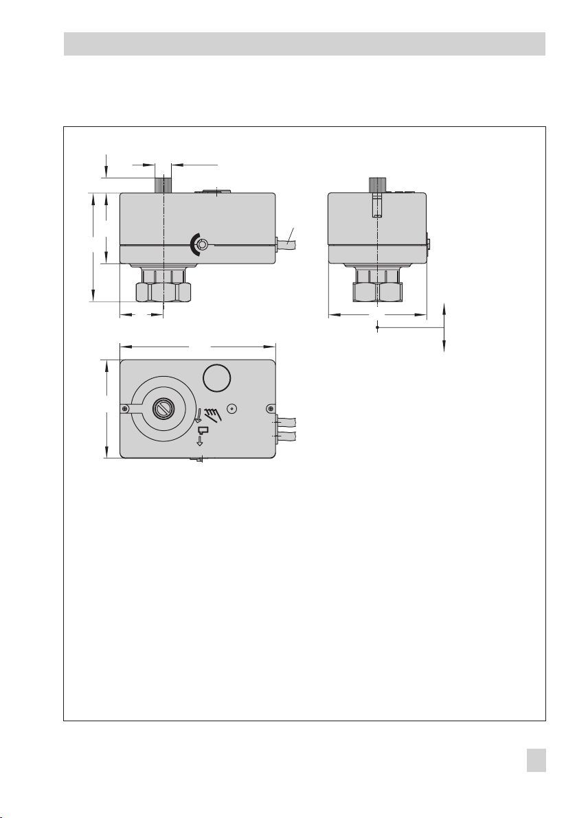
4 Dimensions in mm
Ø 12
11
Dimensions in mm
55
80
32 70 eL einfahrend
114
70
2.5 m
aL ausfahrend
Fig. 6 · Type 5757-7 Controller with Electric Actuator
EB 5757-7 EN 11
Page 12
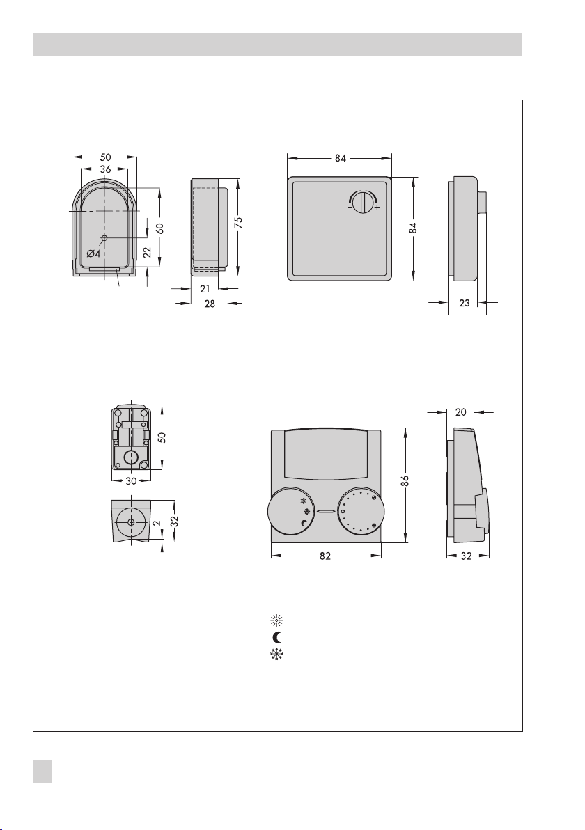
Dimensions in mm
Type 5227-2 Outdoor Sensor,
Pt 1000
Color: RAL 9016
Type 5267-2 Contact
Sensor, Pt 1000
(flow and return flow
temperature measurement)
Fig. 7 · Accessories for heating applications
Type 5257-2 Room Sensor, Pt 1000
(remote adjustment)
Color: RAL 9010
Type 5257-7 Room Panel, Pt 1000
Color: Cover and knobs RAL 9016 · Base RAL 7047
Continuous day mode (rated operation)
Continuous night mode (reduced operation)
Off/frost protection
12 EB 5757-7 EN
Page 13
Functions
5 Functions
Functions and parameters are entered in the TROVIS-VIEW Operator Interface (see
section 6).
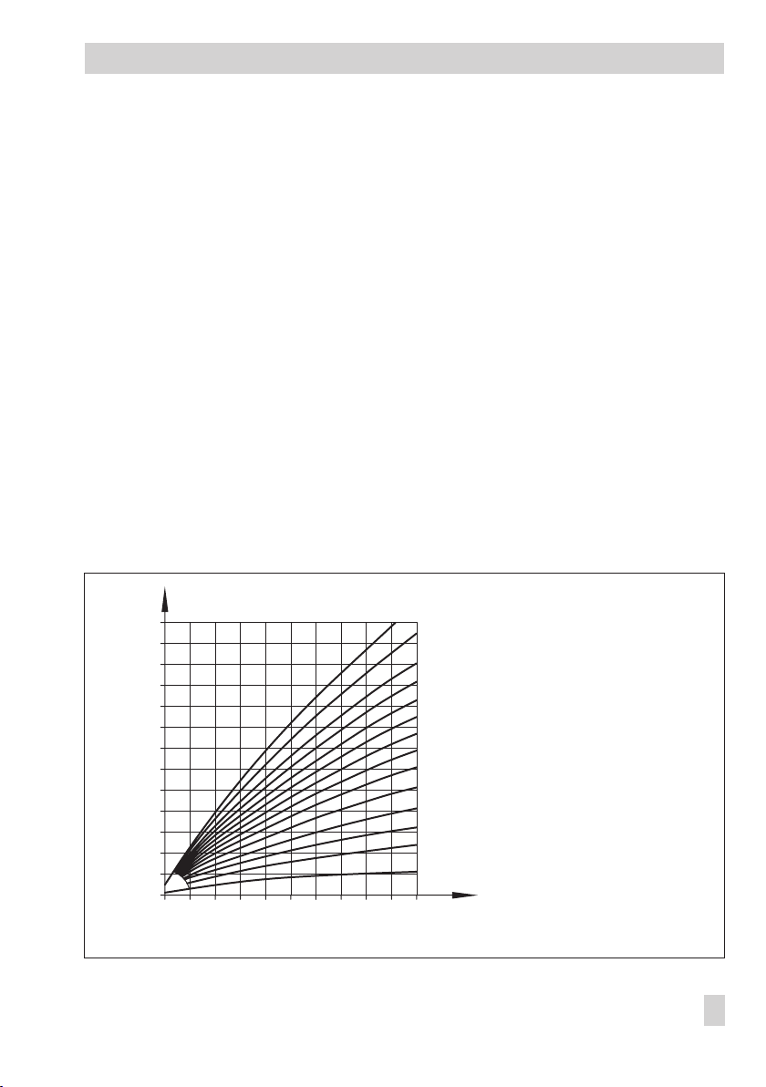
5.1 Outdoor temperature compensated control
In the outdoor temperature compensated control, the flow temperature (tVL) is automatically
adjusted in relationship to the outdoor temperature (t
troller defines the set point for flow temperature as a function of the outdoor temperature
(Fig. 8).
Basically, the following correlation exists: If the outdoor temperature drops, the flow temper
ature rises. By varying the
Gradient
to individual requirements: An increased
whereas a reduced
Gradient
and
Level
Gradient
causes a lower flow temperature. The
heating characteristic parallely upwards or downwards.
In reduced operation, the flow temperature is reduced by the amount set in
setback in reduced operation. The Maximum flow temperature
e parameters limit the flow temperature range. Return flow temperature limitation (see
tur
section 5.5) is an exception as it can reduce the flow temperature without restriction down to
20 °C flow temperature set point.
). The heating characteristic in the con
A
parameters, the characteristic can be adapted
causes an increase in flow temperature,
Level
parameter shifts the
Flow temperature
and
Minimum flow tempera-
-
-
[
C] t
VL
˚
150
140
130
120
110
100
90
80
70
60
50
40
30
20
20 16 12 8 4 0 -4 -8 -12 -16 -20
Fig. 8 · Heating characteristics
3.2
2.9
2.6
2.4
2.2
2.0
1.8
1.6
1.4
1.2
1.0
0.8
0.4
0.2
tVLFlow temperature
Outdoor temperature
t
A
t
A
[
C]
˚
EB 5757-7 EN 13
Page 14
Functions
Functions WE Configuration
F01 – Control mode 1 F01 - 1
F02 – Selecting the reference variable 0 F02 - 0
Parameters WE Range of values
P02 – Flow temperature set-back in reduced
operation
P03 – Min. flow temperature 20 °C 0 to 150 °C
P04 – Max. flow temperature 120 °C 0 to 150 °C
P05 – Heating characteristic gradient 1.6 0.2 to 3.2
P06 – Heating characteristic level 0 K –30 to 30 K
Examples for setting the heating characteristic:
Old building, radiator design 90/70: Gradient approx. 1.8
4
New building, radiator design 70/55: Gradient approx. 1.4
4
New building, radiator design 55/45: Gradient approx. 1.0
4
Underfloor heating depending on arrangement: Gradient smaller than 0.5
4
15 K 0 to 50 K
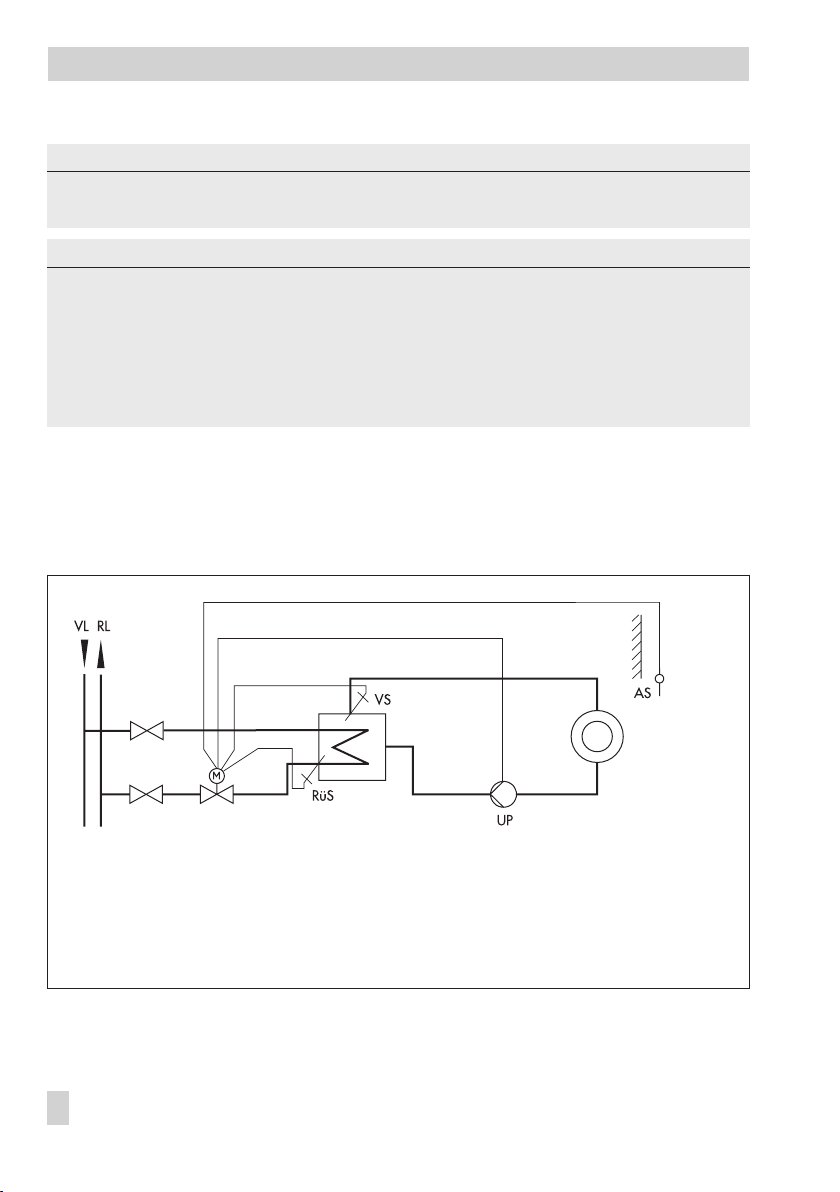
Fig. 9 · Typical application: Outdoor temperature compensated flow temperature control with return flow limitation;
switching between operating modes using a binary contact
14 EB 5757-7 EN
Page 15

Functions
5.1.1 Override using potentiometer
The potentiometer input (e.g. by connecting Type 5257-2 with remote adjustment) can
change either the heating characteristc level or gradient, depending on the configuration.
The parameters
are used to adjust the range (±) in which the influence is to take place.
ter
Functions WE Configuration
F05 – Potentiometer input 0 F05 - 1
F06 – Resistance range of potentiometer 0 F06 - 1 (Type 5257-2)
F07 – Potentiometer function 0 F07 - 0: Level shift
Parameters WE Range of values
P07 – Gradient shift range via potentiometer 1.0 0.0 to 1.5 (only with F 07 - 1)
P08 – Level shift range via potentiometer 15 K 0 to 30 K (only with F 07 - 0)
Examples:
Potentiometer function F07 - 0
4
Heating characteristic gradient
Gradient shift range via potentiometer
The gradient can be shifted between 0.6 and 2.6 (±1.0).
⇒
Potentiometer function F07 - 1
4
Heating characteristic level
Level shift range via potentiometer
The level can be adjusted between –15 K and +15 K (±15 K). The limits adjusted
⇒
for the flow temperature still apply.
Gradient shift range via potentiometer
P05 = 1.6
P07 = 1.0
P06 = 0 K
P08 = 15 K
and
Level shift range via potentiome
F07 - 1: Gradient shift
-
5.1.2 Summer mode
Should the outdoor temperature exceed the
tion/reduced operation
the circulation pump is switched after the
The heating is switched on again when the outdoor temperature falls below the set point.
Parameters WE Range of values
P17 – Outdoor temperature limit value at rated operation 22 °C 0 to 50 °C
P18 – Outdoor temp. limit value at reduced operation 15 °C 0 to 50 °C
P22 – Pump lag time 5 min 1 to 999 min
), the controller switches off the heating, i.e. the valve is closed and
Outdoor temperature limit value(rated opera
Pump lag time
has elapsed.
EB 5757-7 EN 15
-
Page 16

Functions
5.1.3 Delayed outdoor temperature adaptation
The calculated outdoor temperature is used to determine the flow temperature set point. The
heat response is delayed when the outdoor temperature either decreases, increases or in
creases and decreases.
If the outdoor temperature varies by, for example, 12 °C within a very short period of time,
the calculated outdoor temperature is adapted to the actual outdoor temperature in small
Delay
steps. Assuming a
of 3 °C/h, the linear adaptation would take =
123°°C
C/h
= 4 h.
Note!
The delayed outdoor temperature adaptation helps avoid unnecessary overloads of central
heating stations caused by either overheated buildings occurring, for example, due to warm
winds, or temporarily insufficient heating due to the outdoor sensor being exposed to direct
sunshine.
Functions WE Configuration
F04 – Delayed outdoor temperature 0 F04 - 1
Parameter WE Range of values
P16 – Delayed value for outdoor temp. adaptation 3 °C/h 1 to 6 °C/h
-
5.2 Fixed set point control
The flow temperature is controlled to the fixed value in
duced operation, the flow set point is used for the control reduced by the amount in
temperature set-back in reduced operation.
A connected outdoor sensor does not have any
effect on the control.
Functions WE Configuration
F01 – Control mode 1 F01 - 0
Parameters WE Range of values
P01 – Flow temperature set point 70 °C 0 to 150 °C
P02 – Flow temp. set-back in reduced operation 15 K 0 to 50 K
Flow temperature set point
5.2.1 Room temperature influence
On connecting a Type 5257-7 Room Panel, the
the room temperature:
16 EB 5757-7 EN
Flow temperature set point
is influenced by
. In re
Flow
-
Page 17

Functions
AS Outdoor sensor
RüS Return flow sensor
VS Flow sensor
Fig. 10 · Typical application: Fixed set point control with room temperature influence and return flow temperature
limitation; switching between operating modes at room panel (Type 5257-7)
UP Circulation pump
RL District heating network return flow
VL District heating network supply
The heat supply is matched to the required amount over a permanently active flash adaptation. The room sensor is polled at regular intervals (
ature is lower than the
at reduced operation,
.
point
Room temperature limit at rated operationorRoom temperature limit
the flow temperature is raised based on the
TrFlash adaptation).
If the room temper-
Flow temperature set
If the room temperature exceeds the room temperature set point (rated operation/reduced
operation) by the amount in
Maximum room temperature boost
i.e. the valve is closed and the circulation pump is switched off after the
, the heating is switched off,
Pump lag time
has
elapsed.
In the event, the parameter P12 –
TrFlash adaptation
is set to 0, the control is a pure fixed set
point control without room temperature influence.
Note!
We recommend not to select a value that is too low for parameter P12. In particular, in cases
where cooling loads, such as drafts or open windows, affect the control process, short cycles
usually have a negative effect. The heating is directly switched off after the cooling stops.
EB 5757-7 EN 17
Page 18

Functions
Note!
The set points for room temperature entered in TROVIS-VIEW can be reduced or raised by
5 K at the room panel.
Functions WE Configuration
F01 – Control mode 1 F01 - 1
F02 – Selecting the reference variable 0 F02 - 1
Parameters WE Range of values
P01 – Flow temperature set point 70 °C 0 to 150 °C
P12 – TrFlash adaptation 10 min 0 to 100 min
P19 – Room temperature limit at rated operation 20 °C 10 to 40 °C
P20 – Room temperature limit at reduced operation 15 °C 10 to 40 °C
P21 – Maximum room temperature boost 1 K 1 to 6 K
P22 – Pump lag time 5 min 1 to 999 min
5.3 Operating modes
5.3.1 Switchover via binary input
The active binary input determines which operating mode is used. Depending on the configuration, the following applies:
F08 - 0 Open binary input – Rated operation
4
Closed binary input – OFF/Frost protection
F08 - 1 Open binary input – Rated operation
4
Closed binary input – Reduced operation
Note!
It is not possible to connect the Type 5257-7 Room Panel at the same time in this case (see
section 5.3.3 on Switchover via binary input in room panel).
Functions WE Configuration
F05 – Potentiometer input 0 F05 - 0
F08 – Binary input function 0 F08 - 0: Rated operation + OFF/Frost protect.
18 EB 5757-7 EN
F08 - 1: Rated and reduced operation
Page 19

Functions
5.3.2 Switchover via room panel
The operating mode of the controller is determined at the mode selector switch on the
Type 5257-7 Room Panel:
Rated operation (day mode)
Reduced operation (night mode)
OFF/Frost protection
Functions WE Configuration
F05 – Potentiometer input 0 F05 - 1
F06 – Resistance range of potentiometer 0 F06 - 0 (Type 5257-7 Room Panel)
5.3.3 Switchover via binary input in room panel
The terminals 1 and 4 of the Type 5257-7 Room Panel can be bridged by means of an external floating contact (e.g. by a time switch with downstream contactor relay with floating
make or break contact). This enables the controller to switch to the rated operation mode
when the mode selector switch is set to reduced operation or OFF/Frost protection .
The following applies:
BI break contact Operating mode is the same as the mode set at the mode selector
4
switch
BI make contact Operating mode is rated operation,
4
regardless of the mode set at the mode selector switch
Functions WE Configuration
F05 – Potentiometer input 0 F05 - 1
F06 – Resistance range of potentiometer 0 F06 - 0 (Type 5257-7 Room Panel)
5.4 Frost protection
If the controller is in the operating mode OFF/Frost protection (see section 5.3), frost protec
tion measures are initiated if the following applies:
Outdoor temperature < 3 °C (outdoor temperature compensated control) or flow
4
temperature < 15 °C (fixed set point control with room temperature influence)
The circulation pump is switched off and the flow temperature is kept at 20 °C.
5.5 Return flow temperature limitation
The temperature difference between the flow and return flow in a network indicates how well
the energy is used: the greater the difference, the higher the efficiency.
EB 5757-7 EN 19
-
Page 20

Functions
A return flow sensor is sufficient to evaluate the temperature difference when the network
flow temperatures are predetermined. The flow temperature set point is reduced when the
Maximum return flow temperature
measured at the return flow sensor exceeds the limit tem
perature:
The reduction amount is calculated from the deviation of the return flow temperature multi
plied by the factor
Kp Return flow temperature limitation
temperature is reduced by the calculated amount is determined by
ture limitation
.
. The rate at which the return flow
Tn Return flow tempera
The yellow LED blinks slowly if the flow temperature is reduced due to the Return flow tem
perature limitation function
The return flow is not limited if the parameter setting
Tn Return flow temperature limitation
0 even if a return flow sensor is connected.
Function WE Configuration
F11 – Return flow temperature sensor 1 F11 - 1
Parameter WE Range of values
P13 – Maximum return flow temperature 50 °C 10 to 90 °C
P14 – Kp Return flow temperature limitation 1.0 0.1 to 50.0
P15 – Tn Return flow temperature limitation 400 s 0 to 999 s
-
-
-
-
=
5.6 Pump forced operation
A deactivated circulation pump is forced-operated every 24 hours for one minute. This function is disenabled by selecting F10 - 0 or F09 - 1.
Functions WE Configuration
F09 – Binary output function 0 F09 - 0
F10 – Anti-block protection of pump 1 F10 - 1
5.7 External request for heat demand
The controller with electric actuator can issue a heat demand to a higher-level controller
over the binary output BO in rated or reduced operation. In this case, a coupling relay
(contactor relay with floating contact) must be used to adapt the electrical connection.
This function is only possible when the binary output is not configured as a pump output.
Function WE Configuration
F09 – Binary output function 0 F09 - 1
20 EB 5757-7 EN
Page 21

5.8 Control principle
Functions
The controller with electric actuator functions with a PI algorithm (three-point stepping con
trol). The valve reacts to pulses which the digital controller issues when a system deviation
occurs. In particular, the length of the first pulse depends on the size of the system deviation
and the selected gain
rises). Pulse lengths and intervals change until the system deviation is eliminated. The interval
between individual pulses is influenced considerably by the reset time
(the interval time increases as the Tn rises).
control
The valve transit time
needs to move through its travel range from 0 to 100 %.
Note!
Do not change the default setting WE of P11 (Ty = 25 s) for this device.
Parameters WE Range of values
P09 – Kp flow temperature control 2.0 0.1 to 50.0
P10 – Tn flow temperature control 120 s 0 to 999 s
P11 – Ty actuator transit time at rated travel 25 s 10 to 240 s
Kp flow temperature control
Ty actuator transit time at rated travel
(the pulse length increases as the Kp
Tn flow temperature
reflects the time that the valve
-
5.9 Direction of action
Specify the direction of action depending on the valve used.
Function WE Configuration
F03 – Direction of stem action 0 F03 - 0: SAMSON globe valve
F03 - 1: SAMSON three-way valve
Globe valve (F03 - 0)
Actual value < Set point: Actuator stem retracts (globe valve opens)
4
Actual value > Set point: Actuator stem extends (globe valve closes)
4
EB 5757-7 EN 21
Page 22

Functions
Three-way mixing valve (F03 - 1)
Mixing valve for:
Mixing service
Flow
Return flow
Fig. 11 · Type 3226 Three-way Valve mounted onto Type 5757-7 Controller with Electric Actuator
Actual value < Set point: Actuator stem extends (three-way mixing valve opens port
4
AB
A
B
A -> AB and closes port B -> AB)
Actual value > Set point: Actuator stem retracts (three-way mixing valve closes port
4
A -> AB and opens port B -> AB)
22 EB 5757-7 EN
Page 23

Configuration and operation using TROVIS-VIEW interface
6 Configuration and operation using TROVIS-VIEW interface
6.1 General
The TROVIS-VIEW software allows various smart SAMSON devices to be configured over a
common operator interface. It consists of the operator interface, communication server, and
the device-specific module. The software has a Windows Explorer look and feel.
The entire configuration of the controller with electric actuator can be performed over the
TROVIS-VIEW Configuration and Operator Interface.
The TROVIS-VIEW software containing online help and the database module for
Type 5757-7 Controller with Electric Actuator is delivered on a CD-ROM (order number
6661-1066).
Software updates are available in Internet (http://www.samson.de) in Products > Support
and downloads.
Note!
The following instructions include a description on the key functions of the TROVIS-VIEW
software in conjunction with controllers with electric actuators. Refer to the online help in the
? menu for a detailed description.
6.1.1 System requirements
Hardware requirements
PC with Pentium II processor or equivalent (300 MHz or higher), 500 MHz recommended
4
Serial interface or USB/RS-232 adapter
4
Min. 64 MB RAM, 96 MB RAM recommended
4
Min. 150 MB free hard disk space plus approx. 10 to 15 MB additional hard disk space
4
per SAMSON module
SVGA graphic card (min. 800 x 600)
4
CD-ROM drive
4
Software
Operating system: Windows 98, ME, NT 4.xxSP6, 2000 SP2, XP
4
Microsoft.NET Framework Version 1.1 (included on the installation CD-ROM)
4
Internet browser: MS Internet Explorer, version 6.0 and higher
4
EB 5757-7 EN 23
Page 24

Configuration and operation using TROVIS-VIEW interface
6.2 Installing TROVIS-VIEW software
1. Insert the installation CD-ROM to start the installation program.
Once inserted, the CD-ROM usually starts the installation program automatically, de
pending on the configuration of the operating system. If the program does not start auto
matically, double-click setup.exe in the root directory of the CD-ROM in order to install
TROVIS-VIEW.
2. Follow the on-screen prompts and instructions of the installation program.
The TROVIS-VIEW Operator Interface can be used for different SAMSON devices. Note that
the installation program also offers you the option of installing a demo module. To use the
software without restrictions, the software needs to be activated by entering a CD key as fol
lows:
3. After installation, a dialog box will appear, prompting you to enter the CD key, which
you will find on the cover of the original CD-ROM.
Once you have entered the correct CD key and initiated the activation process, a request
code will be automatically generated which contains computer identification details.
Activation
4. The
Internet link to SAMSON’s activation server. Enter the request code and a unique activation code will then be generated and displayed.
(http://support.samson-ag.com: 8082/activate_eng.html)
5. Enter this activation code in TROVIS-VIEW’s
The software is now ready for use without any restrictions in the purchased scope.
dialog box will come up displaying the generated request code and an
Activation
dialog box.
-
-
-
Note!
Refer to the readme.txt file in the root directory of the CD-ROM for further information on in
stallation, software updates and current system requirements.
24 EB 5757-7 EN
-
Page 25

Configuration and operation using TROVIS-VIEW interface
6.3 Starting TROVIS-VIEW and performing settings
You can perform the settings in TROVIS-VIEW either when the actuator is connected (online)
to the PC or without direct connection (offline) (refer to section 7).
Note!
When the device is not connected, the default settings appear on the operator interface or,
alternatively, a stored TROVIS-VIEW file (*.tro) can be loaded and overwritten by selecting
Open in File menu.
1. Start TROVIS-VIEW. The operator interface appears with menubar and toolbar as well as
various folders.
Options
2. In
change the interface language.
Note!
Languages in gray are not available.
3. Select
ter data relevant to the plant, e.g. project
name, plant location, operator.
4. Select
(see sections 8.1 and 8.2) if you want to
load default settings onto the operator
interface.
menu, select
Customer datainEdit
Languages
menu to en
Load Factory DefaultsinEdit
to
-
menu
EB 5757-7 EN 25
Page 26

Configuration and operation using TROVIS-VIEW interface
Properties of data points are indicated by icons on clicking on a folder:
Icon Meaning
Data cannot be changed
Data can be changed
Data point can be executed
Data point is user-defined
Mark to indicate error
Value has exceeded maximum limit
Value has fallen below minimum limit
Connection to the device is interrupted or there is a write protection error
Source of data:
Value has been modified manually
Value has been uploaded from the controller with electric actuator.
In online mode,
Value originates from a stored file
Value has been adopted from memory pen
Value has been changed by the software
X
in the icon indicates a value has been updated.
26 EB 5757-7 EN
Page 27

Configuration and operation using TROVIS-VIEW interface
6.3.1 Activating/deactivating functions
1. Click on
2. Double-click the function block status (0 or I) to change the status of the function.
Right-click on a row to open pop-up window to modify configuration settings:
Modify
Read
Write
Default: ...
Configuration
To change the status of the function block.
Uploads status of the function block from device.
Downloads status of the function block to device.
Resets function block to default setting
(setting in gray to indicate that the status of the
function block is the same as the default setting)
folder to view the function block settings.
EB 5757-7 EN 27
Page 28

Configuration and operation using TROVIS-VIEW interface
6.3.2 Setting parameters
1. Click on
Note! The parameters listed in the screenshot below are default settings.
2. Double-click on the required parameter
to open pop-up window to modify pa
rameter settings.
Parameter
folder to view the parameter settings.
-
28 EB 5757-7 EN
Page 29

Configuration and operation using TROVIS-VIEW interface
Right-click on the required parameter to
open pop-up window to modify parame
ter settings:
Modify
Read
Write
Default: ...
Min ...
Max ...
Opens pop-up window to
modify parameter set
tings.
Uploads parameter value from device.
Downloads parameter value to device.
Resets parameter to default setting (setting in gray to indicate that the
parameter value is the same as the default setting)
Set parameter to the displayed minimum value.
Set parameter to the displayed maximum value.
-
-
6.3.3 Reading operational information
Note!
Operational information can only be read when TROVIS-VIEW is directly connected to the
controller with electric actuator (i.e. in online mode, refer to section 7).
Select
4
Sensors
from the binary input and output.
folder to display actual data measured by the connected sensors as well as
EB 5757-7 EN 29
Page 30

Configuration and operation using TROVIS-VIEW interface
Select the
4
ing the actuator.
Select the
4
Information
Error
subfolder in the
subfolder in the
Diagnostics
Diagnostics
folder to display information concern
folder to display current error messages.
-
30 EB 5757-7 EN
Page 31

Data transmission
7 Data transmission
The TROVIS-VIEW software installed on your PC allows you to configure the controller with
electric actuator either in offline mode (device not connected to a PC) or in online mode (de
vice connected to a PC). To activate online mode, click on the device toolbar. The commu
nication port must be set (see section 7.1)
Online mode (direct data transmission)
The actuator and TROVIS-VIEW are con
nected constantly in online operation. Cur
rent configuration and operating data are
uploaded from the actuator cyclically and
displayed in TROVIS-VIEW. The settings
configured in TROVIS-VIEW can be directly
transferred to the controller with electric ac
tuator.
To enable communication with the PC, connect the serial interface (COM port) to the
serial interface (RJ-12 jack) of the controller
with electric actuator using a SAMSON connecting cable.
In case the PC does not have a COM port, a
USB/RS-232 adapter can be used when
Windows 98, ME, 2000, or XP operating
systems are installed.
-
-
Connecting cable
-
Modular adapter
Memory pen
(also available separately:
order no. 1400-7697)
-
-
Offline mode (indirect data transmission)
There is no constant data communication
between the PC and actuator. Communica
tion must first be established to upload from
the actuator or download data to the actua
tor.
Data can be transferred to the serial
interface over the SAMSON connecting ca
ble or over a memory pen together with a
modular adapter.
A memory pen allows you to simply copy
and download configuration data onto
other devices.
Hardware package
order no. 1400-7704
-
-
-
USB/RS-232 adapter
order no. 8812-0016
Fig. 12 · Accessories for data transmission
EB 5757-7 EN 31
Page 32

Data transmission
Note!
You can only transfer data to the controller with electric actuator after the electrical connec
tion has been made as described in section 3.
7.1 Data transmission between TROVIS-VIEW and the actuator
(connecting cable)
1. Connect the serial port of the PC using
the SAMSON connecting cable to the se
rial interface connection of the actuator.
2. Select
3. Check
4. Click
5. The settings window opens and
CommunicationsinOptions
to open the server settings window. Click
Server settings
Local connection
matically local connect
on OK button to confirm server settings.
Communication
The
Port settings
State: not yet searched appears in the
Automatic detection field.
Click on
TROVIS-VIEW has found the actuator
when State: Device found on ....
appears, click on OK button twice to
confirm settings.
Start
button.
and
boxes and click
window reappears.
button.
button.
Auto-
-
menu
-
32 EB 5757-7 EN
Page 33

Data transmission
7.1.1 Offline operation (indirect data transmission)
In offline mode, there is no constant data communication between the PC and actuator.
Communication must first be established to upload from the actuator and download data to
the actuator.
Downloading data to the actuator:
Download to the deviceinDevice
Select
starts to control after data are downloaded from TROVIS-VIEW.
Uploading data from the actuator:
Select
Upload from deviceinDevice
Uploaded data are indicated in TROVIS-VIEW by the icon.
menu to transfer data to the actuator. The actuator
menu to transfer all the data from the actuator.
Note!
Data transmission can also be performed by clicking the icons in the device toolbar:
click to download data from TROVIS-VIEW to the actuator and, click to upload data
from the actuator and to display them in TROVIS-VIEW.
7.1.2 Online operation (direct data transmission)
The actuator and TROVIS-VIEW are constantly connected in online operation. Current configuration and operating data are uploaded from the actuator cyclically and displayed in
TROVIS-VIEW. Likewise, any settings performed in TROVIS-VIEW are directly transferred to
the actuator.
In the event of a sensor breakage, the interruption in sensor connection is shown without de
lay in the
Activate online operation:
Select
In online mode, in the device toolbar is animated.
Deactivate online operation:
Select
The online mode is cancelled.
Sensors
OnlineinDevice
OnlineinDevice
folder.
menu to activate online mode.
menu while the online mode is activated.
Note!
Alternatively, click in the device toolbar to activate and deactivate online operation.
EB 5757-7 EN 33
-
Page 34

Data transmission
7.2 SAMSON memory pen
The SAMSON memory pen serves as a data carrier and is able to load and store data in its
non-volatile memory.
The memory pen can be loaded with data configured in TROVIS-VIEW and the settings
transferred to one or several controllers with electric actuators. In the same way, the memory
pen can be used to upload data from the actuator allowing you to simply copy the
configuration data from one actuator to another actuator of the same type.
Note!
On inserting a memory pen that is empty or that contains data from another type of device
into the serial interface port of the actuator, the data from the actuator are uploaded to the
memory pen regardless of the status of the memory pen and any other data on the memory
pen will be overwritten.
7.2.1 Data transfer between TROVIS-VIEW and memory pen
1. Plug memory pen (3) together with modular adapter (2) into the serial interface (COM
port) of the PC (Fig. 13).
Fig. 13 · Connecting PC – memory pen
34 EB 5757-7 EN
1 Serial interface
2 Modular adapter
3 Memory pen
Page 35

Data transmission
2. Select
3. Click the
Interface
Start
in the
Memory Pen
menu.
button in Automatic detection field of the dialog box. The computer auto
matically searches for the interface assigned to the memory pen.
Message: “Memory pen found at COM …“
OK
Confirm interface setting by clicking
button.
Downloading data from TROVIS-VIEW to the memory pen
4. Select
5. Click
Download to Memory peninMemory pen
OK
button to start data transmission.
menu
Uploading data from memory pen to TROVIS-VIEW
4. Select
Upload from Memory peninMemory pen
menu to start data transmission.
7.2.2 Data transmission between actuator and memory pen
Perform steps 1 to 3 described in section 7.2.1.
4
3
-
4
Fig. 14 · Type 5757-7 – memory pen
3 Memory pen
4 Serial interface
(RJ 12 jack)
EB 5757-7 EN 35
Page 36

Data transmission
Uploading data from the actuator to
memory pen
4. Select
5. Remove memory pen from PC and plug it
Downloading data from the memory pen
to the actuator
4. Select
5. Remove memory pen from PC and plug it
Modify memory pen status
Memory pen
Check
in the dialog box.
pen
Click
into the serial interface of the actuator
(Fig. 14).
Actuator data are uploaded onto the
memory pen.
The yellow LED under the serial interface
blinks twice several times to indicate that
data transmission is in progress.
Data transmission is completed when the
LED is illuminated continuously.
Remove the memory pen from the actuator.
menu.
Automatically write to memory
OK
button to confirm.
Modify memory pen status
Memory pen
Check
in the dialog box.
pen
Click
into the serial interface of the actuator
(Fig. 14).
Data are downloaded from the memory
pen into the actuator.
The yellow LED under the serial interface
blinks several times to indicate that data
transmission is in progress.
Data transmission is completed when the
LED is illuminated continuously.
Remove the memory pen from the actuator.
menu.
Automatically read from memory
OK
button to confirm.
in
in
36 EB 5757-7 EN
Page 37

Data transmission
7.2.3 Copy function
The memory pen can be used to copy setting data to other Type 5757-7 Actuators as soon
as the data from the actuator have been transferred to the memory pen (indicated by the yel
low LED blinking twice several times).
first data transmission from the actuator.
Automatically write to memory pen
is reset after the
7.2.4 Manual operation
Caution!
Activate the handwheel (red knob) only when the actuator is de-energized.
The controller with electric actuator can be set to manual operation using the memory pen
while the control operation is running:
Perform steps 1 to 3 described in section 7.2.1.
4
4. Select
5. Check either
6. Click
7. Remove memory pen from PC and plug it
8. After removing the memory pen from the
Modify manual operation status
Memory pen
tracts
into the serial interface of the actuator
(Fig. 14).
The valve stem extends or retracts ac
cording to the option selected previously.
actuator, the actuator returns to its nor
mal control state.
menu.
Stem extendsorStem re-
in the dialog box.
OK
button to confirm.
in
-
-
-
Reset manual operation status in memory pen
1. Plug memory pen (3) together with modular adapter (2) into the serial interface (COM
port) of the PC (Fig. 13).
2. Check
3. Click
No manual operation
OK
button to confirm.
in the dialog box.
EB 5757-7 EN 37
Page 38

Appendix
8 Appendix
8.1 Function block list
The function blocks F01 to F11 have the following listed function.
F = Function block WE = Default setting 0 = OFF, 1 = ON
F
Function
01 Control mode 1 0 – Fixed set point control→Section 5.2
02 Selecting the reference
variable
03 Direction of stem action 0 0 – SAMSON globe valve→Section 5.9
04 Delayed outdoor
temperature
05 Potentiometer input 0 0 – Inactive, binary input active→Section 5.3.1
06 Resistance range of
potentiometer
07 Function of potentiometer 0 0 – Heating characteristic level shift→Section 5.1.1
08 Function of binary input 0 0 – BI short-circuited: OFF w. frost protection→Section 5.3.1
09 Function of binary output 0 0 – BO as circulation pump control→Section 5.6
10 Anti-block protection of
pumps
11 Return flow temperature
sensor
WE
Comment
1 – Control with reference variable→Section 5.1
0 0 – Outdoor sensor→Section 5.1
1 – Room sensor→Section 5.2.1
1 – SAMSON three-way valve→Section 5.9
0 0 – Without delay
1 – With delay→Section 5.1.3
1 – Active→Section 5.1.1, 5.3.2, 5.3.3
0 0 – Type 5257-7 Room Panel (1000 … 1100 Ohm)
1 0 – No anti-block protection
1 0 – OFF
Section 5.3.2, 5.3.3
→
1 – Type 5257-2 w. remote adjuster (1000 … 2000 Ohm)
Section 5.1.1
→
1 – Gradient shift→Section 5.1.1
1 – BI short-circuited: Reduced operation→Section 5.3.1
1 – BO as heat demand→Section 5.7
1 – When pumps are deactivated: switched on every 24 h
for 1 min→Section 5.6
1 – ON→Section 5.5
38 EB 5757-7 EN
Page 39

8.2 Parameter list
The parameters have the setting ranges as listed below.
P = Parameter WE = Default setting
Appendix
P
Parameter
01 Flow temperature set point 70 °C 0 to 150 °C
02 Flow temperature set-back in reduced operation 15 K 0 to 50 K
03 Minimum flow temperature 20 °C 0 to 150 °C
04 Maximum flow temperature 120 °C 0 to 150 °C
05 Heating characteristic gradient 1.6 0.2 to 3.2
06 Heating characteristic level 0 K –30 to 30 K
07 Gradient shift range via potentiometer 1.0 0.0 to 1.5
08 Level shift range via potentiometer 15 K 0 to 30 K
09 Kp flow temperature control 2.0 0.1 to 50.0
10 Tn flow temperature control 120 s 0 to 999 s
11 Ty actuator transit time at rated travel 25 s 10 to 240 s
12 Tr flash adaptation 10 min 0 to 100 min
13 Max. return flow temperature 50 °C 10 to 90 °C
14 Kp return flow temperature limitation 1.0 0.1to 50.0
15 Tn return flow temperature limitation 400 s 0 to 999 s
16 Delayed time for outdoor temperature 3.0 °C/h 1.0 to 6.0 °C/h
17 Outdoor temperature limit at rated operation 22 °C 0 to 50 °C
18 Outdoor temperature limit at reduced operation 15 °C 0 to 50 °C
19 Room temperature limit at rated operation 20 °C 10 to 40 °C
20 Room temperature limit at reduced operation 15 °C 10 to 40 °C
21 Max. room temperature boost 1 K 1 to 6 K
22 Pump lag time 5 min 1 to 999 min
WE
Setting range
EB 5757-7 EN 39
Page 40

Appendix
8.3 Customer settings
Function blocks Parameters
FWE
01 1 01 70 °C 0 to 150 °C
02 0 02 15 K 0 to 50 K
03 0 03 20 °C 0 to 150 °C
04 0 04 120 °C 0 to 150 °C
05 0 05 1.6 0.2 to 3.2
06 0 06 0 K –30 to 30 K
07 0 07 1.0 0.0 to 1.5
08 0 08 15 K 0 to 30 K
09 0 09 2.0 0.1 to 50.0
10 1 10 120 s 0 to 999 s
11 1 11 25 s 10 to 240 s
Setting
performed P WE
12 10 min 0 to 100 min
13 50 °C 10 to 90 °C
14 1.0 0.1 to 50.0
15 400 s 0 to 999 s
16 3.0 °C/h 1.0 to 6.0 °C/h
17 22 °C 0 to 50 °C
18 15 °C 0 to 50 °C
19 20 °C 10 to 40 °C
20 15 °C 10 to 40 °C
21 1 K 1 to 6 K
22 5 min 1 to 999 min
Setting
performed
Setting range
40 EB 5757-7 EN
Page 41

EB 5757-7 EN 41
Page 42

Index
Index
A
Accessories
Communication . . . . . . . . . . . . . . . . . 6
Heating applications . . . . . . . . . . . . . 6
Activation code. . . . . . . . . . . . . . . . . . . 24
Actuator stem . . . . . . . . . . . . 5, 7, 21 - 22
Anti-block protection . . . . . . . . . . . . . . . 20
C
Contact sensor (Type 5267-2)
Dimensional drawing. . . . . . . . . . . . 12
Control
Fixed set point. . . . . . . . . . . . . . . . . 16
Outdoor temperature compensated. . 13
Controller with electric actuator
Design and principle of operation. . . . 5
Dimensional diagram. . . . . . . . . . . . 11
Copy function with memory pen. . . . . . . 37
Coupling nut. . . . . . . . . . . . . . . . . . . . 5, 7
Customer data . . . . . . . . . . . . . . . . . . . 25
Customer settings . . . . . . . . . . . . . . . . . 40
D
Data transmission . . . . . . . . . . . . . 31 - 37
Accessories . . . . . . . . . . . . . . . . . . . 31
Offline mode. . . . . . . . . . . . . . . 31, 33
Online mode. . . . . . . . . . . . . . . 31, 33
with connecting cable . . . . . . . . . . . 32
with memory pen. . . . . . . . . . . . . . . 34
Delayed outdoor temperature
adaptation . . . . . . . . . . . . . . . . . . . . . . 16
E
Electrical connection . . . . . . . . . . . . . . . . 8
Wiring diagram . . . . . . . . . . . . . . . 10
Electrical connections
Wiring diagram . . . . . . . . . . . . . . . . 9
External request for heat demand. . . . . . 20
F
Fixed set point control . . . . . . . . . . . . . . 16
Room temperature influence . . . . . . . 16
Flow temperature . . . . . . . . . . . . . . . . . 13
Forced operation of pump . . . . . . . . . . . 20
Frost protection. . . . . . . . . . . . . . . . . . . 19
Function block list . . . . . . . . . . . . . . 16, 38
H
Handwheel. . . . . . . . . . . . . . . . . . . . . . . 7
Hardware package . . . . . . . . . . . . . . 6, 31
Hardware requirements. . . . . . . . . . . . . 23
Heating characteristic . . . . . . . . . . . . . . 13
Gradient. . . . . . . . . . . . . . . . . . . . . 13
Level. . . . . . . . . . . . . . . . . . . . . . . . 13
I
Installating the software . . . . . . . . . . . . . 24
M
Manual operation . . . . . . . . . . . . . . . . . 37
Memory pen. . . . . . . . . . . . . . . . . . . . . . 6
Copy function . . . . . . . . . . . . . . . . . 37
Downloading data
Actuator . . . . . . . . . . . . . 36
TROVIS-VIEW . . . . . . . . . . 35
Manual operation . . . . . . . . . . . . . . 37
Uploading data
TROVIS-VIEW . . . . . . . . . . 35
Mounting position . . . . . . . . . . . . . . . . . . 7
O
Offline mode . . . . . . . . . . . . . . . . . . . . 33
Online mode . . . . . . . . . . . . . . . . . . . . 31
Operating direction
Globe valve . . . . . . . . . . . . . . . . . . 21
Three-way valve . . . . . . . . . . . . . . . 22
Operating mode switchover
Binary input . . . . . . . . . . . . . . . . . . 18
Binary input on room panel . . . . . . . 19
42 EB 5757-7 EN
Page 43

Room panel. . . . . . . . . . . . . . . . . . . 19
Outdoor sensor (Type 5227-2)
Dimensional diagram. . . . . . . . . . . . 12
Outdoor temperature compensated control
. . . . . . . . . . . . . . . . . . . . . . . . . . . . . . 13
Outdoor temperature adaptation . . . 16
Override using potentiometer . . . . . . 15
Outdoor temperature limit . . . . . . . . . . . 15
P
Parameter list . . . . . . . . . . . . . . . . . . . . 39
Plug stem . . . . . . . . . . . . . . . . . . . . . . . . 5
Potentiometer input . . . . . . . . . . . . . . . . . 9
Pump anti-block protection. . . . . . . . . . . 20
R
Request for heat demand (external) . . . . 20
Return flow temperature limitation . . . . . 19
Room panel (Type 5257-7)
Dimensional drawing. . . . . . . . . . . . 12
Electrical connection . . . . . . . . . . . . 10
Room sensor (Type 5257-2). . . . . . . . . . . 8
Dimensional drawing. . . . . . . . . . . . 12
Electrical connection . . . . . . . . . . . . . 9
Permissible temperatures/degree of pro-
tection . . . . . . . . . . . . . . . . . . . . . . . 6
Room temperature influence
Fixed set point control . . . . . . . . . . . 16
Outdoor temperature compensated
control . . . . . . . . . . . . . . . . . . . . . . 15
RS-232 adapter . . . . . . . . . . . . . . . . . . 31
T
Three-point stepping control. . . . . . . . . . 21
Toolbar . . . . . . . . . . . . . . . . . . . . . . . . 25
Travel indicator. . . . . . . . . . . . . . . . . . . . 5
TROVIS-VIEW. . . . . . . . . . . . . . . . . . . . . 6
Icons. . . . . . . . . . . . . . . . . . . . . . . . 26
Operation . . . . . . . . . . . . . 26 - 27, 29
Starting and setting . . . . . . . . . . . . . 25
System requirements . . . . . . . . . . . . 23
V
Valve spring . . . . . . . . . . . . . . . . . . . . . . 5
S
Serial interface connection. . . . . . . . . . . 35
Summer mode . . . . . . . . . . . . . . . . . . . 15
System requirements . . . . . . . . . . . . . . . 23
EB 5757-7 EN 43
Page 44

SAMSON AG · MESS- UND REGELTECHNIK
Weismüllerstraße 3 · 60314 Frankfurt · Germany
Phone: +49 69 4009-0 · Fax: +49 69 4009-1507
Internet: http://www.samson.de
EB 5757-7 EN
S/Z 2005-10
 Loading...