

Page 1
EB 5206 EN
Translation of original instructions
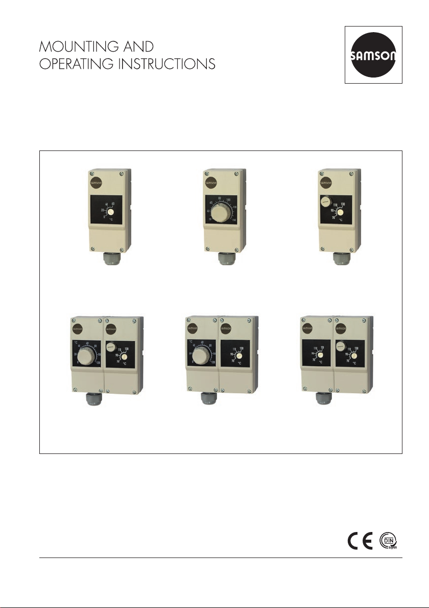
Type 5343 Safety
Temperature Monitor
(STM)
Type5347 Double
Thermostat (TR/STL)
Type5344 Temperature
Regulator (TR)
Type5348 Double
Thermostat (TR/STM)
Thermostats
Type5343 · Type5344 · Type5345
Type5347 · Type5348 · Type5349
Edition October 2017
Type 5345 Safety
Temperature Limiter (STL)
Type5349 Double
Thermostat (STM/STL)
Page 2
Note on these mounting and operating instructions
These mounting and operating instructions assist you in mounting and operating the device
safely. The instructions are binding for handling SAMSON devices.
Î For the safe and proper use of these instructions, read them carefully and keep them for
later reference.
Î If you have any questions about these instructions, contact SAMSON‘s After-sales Service
Department (aftersalesservice@samson.de).
The mounting and operating instructions for the devices are included in
the scope of delivery. The latest documentation is available on our website
at www.samson.de > Service & Support > Downloads > Documentation.
Denition of signal words
!
DANGER
Hazardous situations which, if not avoided,
will result in death or serious injury
!
WARNING
Hazardous situations which, if not avoided,
could result in death or serious injury
2 EB 5206 EN
!
NOTICE
Property damage message or malfunction
Note
Additional information
Tip
Recommended action
Page 3

Contents
1 General safety instructions .............................................................................4
2 Design and principle of operation ..................................................................5
2.1 Typetesting ....................................................................................................5
2.2 Technical data ...............................................................................................6
2.3 Mounting accessories .....................................................................................9
3 Installation ..................................................................................................10
3.1 Mounting position ........................................................................................10
3.2 Contact thermostat .......................................................................................11
3.3 Mounting the thermowell ..............................................................................11
3.3.1 Wall mounting with the capillary tube to the thermowell ..................................12
3.3.2 Mounting on tanks or in pipes .......................................................................12
4 Electrical connection ....................................................................................14
5 Operation ...................................................................................................15
5.1 Temperature regulator (TR) ............................................................................15
5.2 Safety temperature monitor (STM) .................................................................15
5.3 Safety temperature limiter (STL) .....................................................................15
7 Lead sealing ................................................................................................16
6 Dimensions in mm .......................................................................................16
8 EU declarations of conformity ......................................................................20
EB 5206 EN 3
Page 4

General safety instructions
1 General safety instructions
For your own safety, follow these instructions concerning the mounting, start up, and opera-
tion of the thermostat:
− The thermostat is to be mounted, started up or operated only by trained and experienced
personnel familiar with the product.
According to these mounting and operating instructions, trained personnel refers to
individuals who are able to judge the work they are assigned to and recognize possible
dangers due to their specialized training, their knowledge and experience as well as
their knowledge of the applicable standards.
− Upon installation of the electric cables and connecting the device, observe the VDE
regulations as well as the regulations of your local power supplier. Make sure all
electrical connections are installed only by trained and experienced personnel.
To avoid damage to any equipment, the following also applies:
− Proper shipping and storage are assumed.
Note
The device with a CE marking fullls the requirements of the Directives 2014/30/EU and
2014/30/EU, 2014/35/EU and 2011/65/EU.
The EU declarations of conformity are included in the Appendix of these instructions.
4 EB 5206 EN
Page 5
Design and principle of operation
2 Design and principle of oper-
ation
The thermostats are equipped with a
changeover contact. When the thermostat is
triggered, the connection between connections 1 and 2 are interrupted and the connections 1 and 4 are connected (see Fig.5
on page14).
Safety temperature monitor (STM)
A snap-action switch in the STM is triggered
when the temperature at the temperature
sensor rises above the adjusted set point.
When the temperature falls below the set
point by approximately 8K, the switch re-
turns to its original position.
The contact opens or closes when the temperature at the temperature sensor falls below –20°C. It automatically closes or opens
again when the temperature at the temperature sensor rises above –20°C.
The STM is triggered when the capillary tube
breaks.
Temperature regulator (TR)
The snap-action switch is triggered when the
temperature at the temperature sensor rises
above the adjusted set point. When the temperature falls below the set point by approximately 4K, the switch returns to its original
position.
Safety temperature limiter (STL)
The snap-action switch is triggered and
locked when the temperature at the temperature sensor rises above the adjusted set
point. When the temperature falls below the
set point by approximately 10%, the
snap-action switch can be unlocked manual-
ly.
The contact opens or closes when the temperature at the temperature sensor falls below –20°C. It automatically closes or opens
again when the temperature at the temperature sensor rises above –20°C.
The contact opens or closes when the system
fails. It is not possible to unlock the device.
2.1 Typetesting
The thermostats are tested by the German
Technical Inspectorate (TÜV) according to
DINEN14597.
Type DIN register number
5343 STW1209
5344 TR1208
5345 STB1207
EB 5206 EN 5
Page 6
General safety instructions
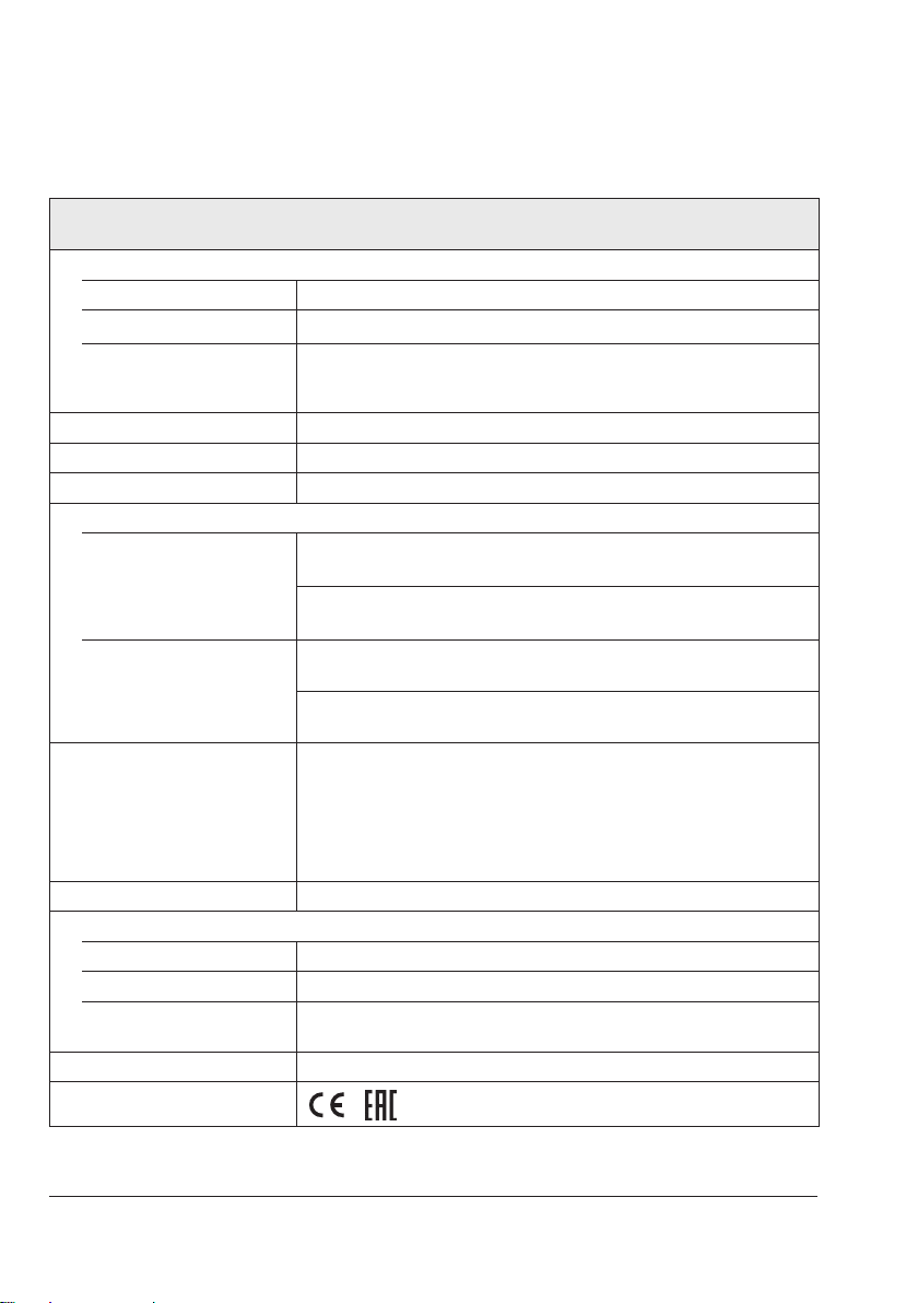
2.2 Technical data
Single thermostats: Type5343 (STM), Type5344 (TR), Type5345 (STL)
Double thermostats: Type5347 (TR/STL), Type5348 (TR/STM), Type5349 (STM/STL)
Permissible ambient temperature
Transportation and storage –30 to +80°C
Service Max. 80°C
Max. pipe temperature when
mounted as a contact
thermostat
Degree of protection IP 54 according to EN60529
Cable entry M20x1.5 cable gland, suitable for 6 to 12mm cable diameter
Minimum switching capacity AC/DC = 24V, 100mA
Maximum switching capacity
Temperature regulator (TR),
safety temperature monitor
(STM)
Safety temperature limiter
(STL)
Inuence of mean ambient
temperature based on the set point
Connection Spring-cage terminals, 0.75 to 2.5mm² wire cross-section
Materials
Bottom section of the housing PA (reinforced)
Housing cover ABS with window (PMMA)
Temperature sensor, capillary
tube
Weight Single thermostat approx. 0.225kg · Double thermostat approx. 0.45kg
Compliance
Max. 120°C
With 230VAC +10%
With 230VDC +10%
With 230VAC +10%
With 230VDC +10%
A shift of the switching point arises when the ambient temperature at the
knob and at the capillary tube deviates from the calibration ambient temperature of +22°C:
Higher ambient temperature g Lower switching point
Lower ambient temperature g Higher switching point
This inuence is minimized by temperature compensation.
Cu (copper)
1)
·
NC contact: 16A (2.5); cos φ = 1 (0.6)
NO contact: 6.3A (2.5); cos φ = 1 (0.6)
NC contact: 0.25A
NO contact: 0.25A
NC contact: 16A (2.5); cos φ = 1 (0.6)
Signal contact: 2A (2.5); cos φ = 1 (0.4)
NC contact: 0.25A
Signal contact: 0.25A
1)
No EAC compliance for Type5349
6 EB 5206 EN
Page 7
General safety instructions
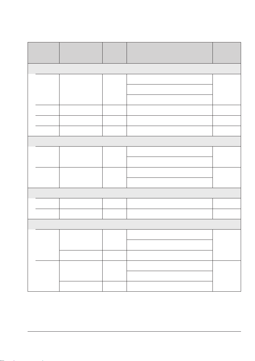
Type Set point range
Safety temperature monitors (STM)
5343-1 0 to 60°C 8K
5343-2 40 to 100°C 8K Range: 40 to 100 °C 0K –8.5K 125°C
5343-3 70 to 130°C 8K Range: 70 to 130 °C 0K –8.5K 155°C
5343-4 35 to 95°C 8K Range: 35 to 95 °C 0K –8.5K 120°C
Temperature regulators (TR)
5344-1 0 to 120°C 3K
5344-2 20 to 150°C 4K
Safety temperature limiters (STL)
5345-1 70 to 130°C 8K Range: 70 to 130 °C +8.5K –8.5K 155°C
5345-2 30 to 90°C 8K Range: 30 to 90 °C 0K –8.5K 115°C
Switching dif-
ferential
Switching point accuracy
Range: 0 to 25 °C 0K –8.5K
Range: 35 to 60 °C 0K –8.5K
Range: 0 to 80 °C +7.2K –7.2K
Range: 80 to 120 °C +3.6K –3.6K
Range: 20 to 106 °C +7.8K –7.8K
Range: 106 to 150 °C +3.9K –3.9K
Max.
medium
temperature
85°CRange: 25 to 35 °C 0K –6.0K
145°C
175°C
Double thermostats (TR/STL)
5347-1
TR: 0 to 120°C 3K
STL: 70 to 130°C 8K Range: 70 to 130 °C 0K –8.5K
TR: 0 to 120°C 3K
5347-2
STL: 30 to 90°C 8K Range: 30 to 90 °C 0K –8.5K
Range: 0 to 80 °C +7.2K –7.2K
145°CRange: 80 to 120 °C +3.6K –3.6K
Range: 0 to 80 °C +7.2K –7.2K
115°CRange: 80 to 120 °C +3.6K –3.6K
EB 5206 EN 7
Page 8
General safety instructions
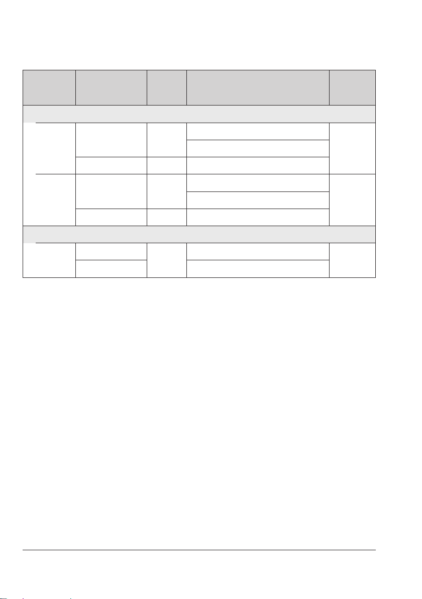
Type Set point range
Double thermostats (TR/STM)
TR: 0 to 120°C 3K
5348-1
STM: 70 to 130°C 8K Range: 70 to 130 °C 0K –8.5K
TR: 0 to 120°C 3K
5348-2
STM: 40 to 100°C 8K Range: 40 to 100 °C 0K –8.5K
Double thermostats (TR/STM)
STM: 70 to 130°C
5349-1
STL: 30 to 90°C Range: 30 to 90 °C 0K –8.5K
Switching dif-
ferential
8K
Switching point accuracy
Range: 0 to 80 °C +7.2K –7.2K
Range: 0 to 80 °C +7.2K –7.2K
Range: 70 to 130 °C 0K –8.5K
Max.
medium
temperature
145°CRange: 80 to 120 °C +3.6K –3.6K
125°CRange: 80 to 120 °C +3.6K –3.6K
145°C
8 EB 5206 EN
Page 9

General safety instructions
2.3 Mounting accessories
Thermowells
The thermostat is supplied without a thermowell. The following thermowells are available for
single and double thermostats as accessories:
Thermowell for single thermostat Max. pressure at 150°C Order no.
Nickel-plated brass · CuZn (2.0401)
100x8mm 48bar 1400-9844
150x8mm 48bar 1400-9845
200x8mm 48bar 1400-9846
CrNiMo steel (1.4571)
100x8mm 88bar 1400-9848
150x8mm 88bar 1400-9849
300x8mm 88bar 1400-9850
Thermowell for double thermostat Max. pressure at 150°C Order no.
Nickel-plated brass · CuZn (2.0401)
100 x (2x 8) mm 48bar 1400-9901
150 x (2x 8) mm 48bar 1400-9851
CrNiMo steel (1.4571)
100x15mm 48bar 1402-0340
150x15mm 48bar 1400-9853
300x15mm 48bar 1400-9854
Note
The scope of delivery of the thermowell includes:
− A clip to fasten the capillary tube to the thermowell (see section3.3.1)
− A small metal plate with screw to attach the thermostat to the thermowell (see sec-
tion3.3.2)
Strap
Strap for mounting the contact thermostat (15 to 100mm
Order no.: 1400-9865
pipe diameter)
EB 5206 EN 9
Page 10

Installation
2
5a
6
3 Installation
!
NOTICE
Inadequate protection against water jets
through insufcient sealing.
− Do not remove the seals in the housing
(1) and on the set point adjuster of the
temperature regulator (4). See Fig.1.
− The thermostat must only be operated
with an inserted seal (6). See Fig.1.
!
NOTICE
Risk of thermostat malfunction due to
measuring uid escaping upon breakage of
the capillary tube.
− Do not bend or cut the capillary tube.
− Do not use a smaller bending radius
than 5mm.
Table 1: Properties of the measuring uid
Dangerous reaction No
Ignition temperature 375°C
Water hazard Class 1
Slightly contaminating
Toxicological specications
Irritant No
Health hazard No
Toxic No
3.1 Mounting position
Contact thermostat
The thermostat must not be suspended with
the bottom of the housing (containing the
sensor) facing upwards.
Thermostat with thermowell
The valve can be mounted in any desired
position.
1 Thermostat
2 Sensor
3 Capillary tube
4 Set point adjuster (TR only)
5a Spring for unlocking (STL only)
6 Seal
Necessary seals for degree of
protection IP54
Fig.1: Necessary seals for degree of protection IP54
3
1
TR
4
10 EB 5206 EN
Page 11

Installation
1
8
3.2 Contact thermostat
3.3 Mounting the thermowell
Single thermostats can be mounted onto
pipes with diameters between 15 and
100mm. A strap is required in this case (see
section2.3, Mounting accessories).
Note
The sensors of double thermostats share the
same thermowell. See section2.3.
1. Insert seal (6) as shown in Fig.2.
2. Thread the strap (8) behind the sensor
holder at the back of the housing (1).
3. Use the strap to attach the thermostat to
the pipe.
4. Unscrew the front cover of the thermo-
stat.
5. Connect the wiring as described in sec-
Before fastening the thermostat, uncoil the
capillary tube to the required length:
− For wall mounting, the required length
depends on the required capillary tube
and length of the thermowell
− For mounting the thermostat on tanks/in
pipes, the required length depends on
the length of the thermowell
tion4.
6. Screw the front cover back onto the ther-
mostat.
TR: Place the set point adjuster onto the tem-
perature regulator.
!
NOTICE
Risk of thermostat malfunction due to measuring uid escaping upon breakage of the capillary tube.
Do not pull at the sensor on uncoiling the
capillary tube.
1. Unscrew the front cover of the thermostat.
2. Detach the sensor from the back of the
6
thermostat.
3. Route the sensor through the back of the
housing to the front.
2
4. Uncoil the capillary to the required
length (Fig.4a).
5. Route the sensor again through the back
1 Thermostat
2 Sensor
6 Seal
8 Strap
Fig.2: Mounting a contact thermostat
of the housing (Fig.4a).
6. Insert seal (6) as shown in Fig.4b or
Fig.4c.
Î Proceed as described in section3.3.1 or
in section3.3.2 depending on how the
thermostat is to be mounted.
EB 5206 EN 11
Page 12
Installation
95
42.4 95.4
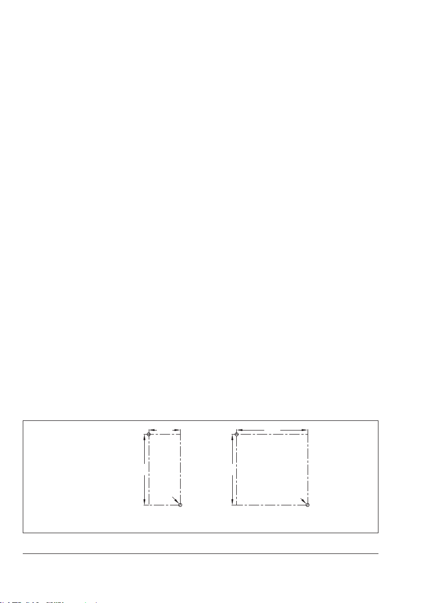
3.3.1 Wall mounting with the capillary tube to the thermowell
The thermostats are fastened to the wall using two screws (not included in the scope of
delivery).
7. Drill holes in wall as shown in Fig.3.
8. Insert the seal (6).
9. Fix the capillary tube in the notch at the
side of the thermostat housing or let it
run down the middle (Fig.4b).
10. Fasten the back of the housing (1) using
two screws to the wall.
11. Screw the thermowell (7) into the pipe or
tank.
12. Push the sensor (2) as far as it will go in-
to the thermowell (7).
13. Fasten the capillary tube (3) to the ther-
mowell (7) using the supplied clip (7a).
14. Connect the wiring as described in sec-
tion4.
15. Screw the front cover back onto the ther-
mostat.
TR: Place the set point adjuster onto the tem-
perature regulator.
3.3.2 Mounting on tanks or in pipes
The thermostats are fastened to the thermowells which are screwed into place.
7. Insert the seal (6).
8. Screw the thermowell (7) into the pipe or
tank.
9. Insert the small metal plate (7b) at the
back of the housing (1) and secure in
place with the screw (7c).
10. Push the sensor (2) as far as it will go in-
to the thermowell (7), making sure that
the round hole at the back of the housing
(1) rests on the collar on the thermowell.
11. Push the thermostat approx. 2mm
lengthways toward the SAMSON logo to
allow the thermowell to engage.
12. Tighten screw (7c) until the housing is
xed into place on the thermowell.
13. Connect the wiring as described in sec-
tion4.
14. Screw the front cover back onto the ther-
mostat.
TR: Place the set point adjuster onto the tem-
perature regulator.
Single thermostat Double
Ø 4.5
Fig.3: Drill templates
12 EB 5206 EN
thermostat
95
Ø 4.5
Page 13

Fig.4a: Uncoiling the capillary tube
7
6
2
1
Installation
Fig.4b Wall mounting with the capillary tube to the
Fig.4c Mounting on tanks or in pipes
thermowell
7c
7a 3
6
7b
7
2
1
1 Thermostat
2 Sensor
3 Capillary tube
6 Seal
7 Thermowell
7a Clip
7b Metal plate
7c Screw
Fig.4: Mounting the thermowell
EB 5206 EN 13
Page 14

Electrical connection
4 Electrical connection
!
DANGER
Risk of electric shock.
− Upon installation of the electric cables,
you are required to observe the regulations concerning low-voltage installations
according to DINVDE0100 as well as
the regulations of your local power supplier.
− Only use a suitable power supply which
guarantees that no dangerous voltages
reach the device in normal operation
and in the event of a fault in the system
or any other system parts.
− Connect the grounding conductor to the
PE terminal.
− The wires of double thermostats are routed
through the opening in the intermediate
wall to the second thermostat. Seal the
opening not used for cable entry with a
blanking cap.
Cable entry
Route the wires through the cable gland
(M20x1.5) into the inside of the thermostat.
The spring-clamp terminals are designed for
a wire cross-section of 0.75 to 2.5mm².
Wiring
Open the thermostat housing and wire the
thermostat according to Fig.5:
− Rigid wire ends: strip 11 to 13mm insu-
lation off the cable and place it into the
terminal point (
) as far it will go.
− Flexible wire ends without ferrules: use a
slotted screwdriver to keep the spring
open (in
the terminal point (
) and place the wire ends into
) as far they will
go.
− Flexible wire ends with ferrules: t
ferrules to the wire ends. Refer to
EN60947-1. Use a suitable crimping
tool.
Place the wire ends into the terminal point
(
) as far they will go.
Note
The wire ends can be pulled out by holding
the spring open with a slotted screwdriver (in
).
NC contact
NO contact
Temperature regulator (TR)
Safety temperature monitor
Safety temperature limiter
Fig.5: Electrical connection
1 – 2
1 – 4
(STM)
(STL)
24 1
1
42
1
42
14 EB 5206 EN
Page 15

Operation
4a
5a
5 Operation
5.1 Temperature regulator (TR)
Adjust the set point at the set point adjuster
(4).
Limiting the set point range
The lower range value and upper range value of the set point range can be limited.
4
4 Set point adjuster
4a Pin to limit the set point range
5.2 Safety temperature monitor (STM)
Open the thermostat housing and adjust the
set point using a at-blade screwdriver.
5.3 Safety temperature limiter (STL)
Open the thermostat housing and adjust the
set point using a at-blade screwdriver.Open
the thermostat housing and adjust the set
point using a at-blade screwdriver.
Unlocking safety temperature limiters
Note
The safety temperature limiter can only be
reset after the temperature has fallen below
the adjusted limit by approximately 10%.
Use a at-blade screwdriver to unlock the
thermostat.
1. Turn the set point adjuster (4) to a value
within the required temperature range.
2. Pull the set point adjuster (4) off the tem-
perature regulator.
3. Break off the pin (4a).
4. Insert the pin (4a) at the point where the
temperature is to be limited (min./max.
temperature).
5. Place the set point adjuster back on the
temperature regulator.
EB 5206 EN 15
1. Unscrew the screw lid (5).
2. Use a at-blade screwdriver to move the
spring (5a) from the bottom to the top as
far as it will go.
5
5 Screw lid
5a Spring for unlocking
Page 16

Lead sealing
16
30
Ø 6
95
**
Ø8
5
300
7 Lead sealing
!
NOTICE
Impaired thermostat functioning due to incorrectly attached lead-seal.
Only lead-seal in the gray-colored area.
Note
Drill the holes for lead sealing. The lead-seal
is not included in the scope of delivery.
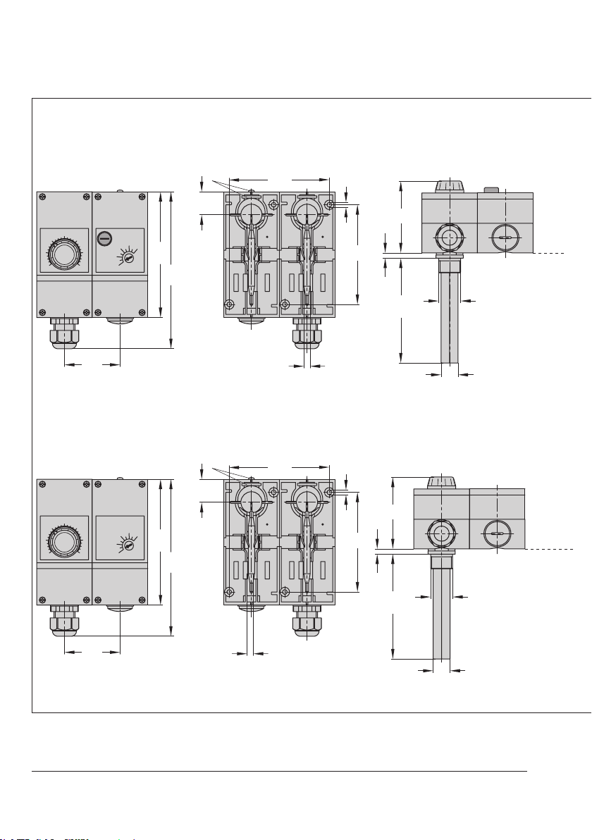
6 Dimensions in mm
15
8
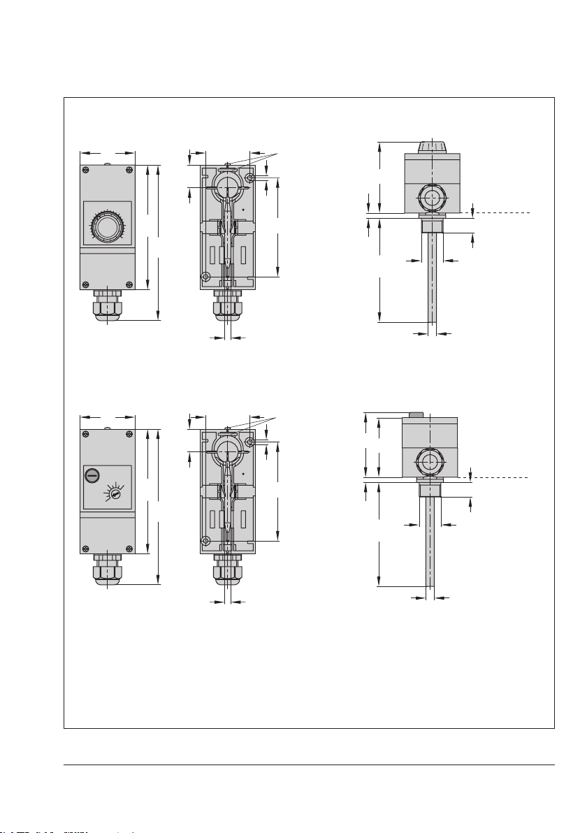
Single thermostats
Type 5343 Safety Temperature Monitor (STM) Dimensions with thermowell (accessories)
53 42.4
22
58
Housing without thermowell
120
˚C
150
16 EB 5206 EN
Ø 4.5
200
150
100
15
G1/2
Page 17
Dimensions in mm
**
95
Ø 6
Ø8
5
95
**
Ø 6
Ø8
300
Type5344 Temperature Regulator (TR) Dimensions with thermowell (accessories)
53 42.4
22
Ø 4.5
120
150
300
70
200
150
Housing
without ther-
mowell
15
G1/2
100
Type 5345 Safety Temperature Limiter (STL) Dimensions with thermowell (accessories)
53 42.4
22
120
˚C
150
Ø 4.5
635
58
200
150
100
Housing
without ther-
mowell
15
G1/2
** Metal plate and screw for fastening the
thermostat onto the thermowell (wall
mounting)
EB 5206 EN 17
Page 18
Dimensions in mm
95
**
Ø 6
Ø15
5
˚C
120
150
106
95.4
22
Ø 4.5
95
**
Ø 6
G1/2
Ø15
100
150
300
63
58
5
95
**
Ø 6
Ø15
5
Double thermostats
Type5347 Double Thermostat (TR/STL)
22
120
˚C
150
106
Type5348 Double Thermostat (TR/STM)
22
120
˚C
150
95.4
95.4
Dimensions with thermowell (accessories)
70
Ø 4.5
100
150
300
G1/2
Dimensions with thermowell (accessories)
70
Ø 4.5
Housing
without ther-
mowell
Housing
without
thermowell
G1/2
106
100
150
300
18 EB 5206 EN
Page 19

Dimensions in mm
95
**
Ø 6
Ø15
100
63
5
Type5349 Double Thermostat (TR/STM)
22
120
˚C
150
106
95.4
Dimensions with thermowell (accessories)
58
Ø 4.5
150
300
G1/2
** Metal plate and screw for fastening
the thermostat onto the thermowell
(wall mounting)
Housing
without
thermowell
EB 5206 EN 19
Page 20
EU declarations of conformity
SAMSON AKTIENGESELLSCHAFT
Weismüllerstraße 3
Telefon: 069 4009-0 · Telefax: 069 4009-1507
E
Revison 07
ce_5344-0_de_en_fra_rev07.pdf
Revison 07
ce_5343-0_de_en_fra_rev07.pdf
8 EU declarations of conformity
61000-6-2:2005, EN 61000-6-3:2007
+A1:2011, EN 61326-1:2013
EN 50581:2012
Au nom du fabricant.
-Mail: samson@samson.de
Typ/Type/ Type 5344
Régulateur de température (TR)
Weismüllerstraße 3
D-60314 Frankfurt am Main
Deutschland/Germany/Allemagne
SAMSON AKTIENGESELLSCHAFT
Déclaration UE de conformité
Temperaturregler (TR) / Temperature Controller (TR) /
60314 Frankfurt am Main
EU Konformitätserklärung / EU Declaration of Conformity /
EMC 2014/30/EU
Die alleinige Verantwortung für die Ausstellung dieser Konformitätserklärung trägt der Hersteller/
This declaration of conformity is issued under the sole responsibility of the manufacturer/
La présente déclaration de conformité est établie sous la seule responsabilité du fabricant.
Für das folgende Produkt/ For the following product /Nous certifions que le produit
the conformity with the relevant Union harmonisation legislation is declared with/
wird die Konformität mit den einschlägigen Harmonisierungsrechtsvorschriften der Union bestätigt/
est conforme à la législation d'harmonisation de l'Union applicable selon les normes:
Typ/Type/ Type 5343
Déclaration UE de conformité
EU Konformitätserklärung / EU Declaration of Conformity /
Die alleinige Verantwortung für die Ausstellung dieser Konformitätserklärung trägt der Hersteller/
This declaration of conformity is issued under the sole responsibility of the manufacturer/
Contrôleur de température de sécurité (STW)
Sicherheitstemperaturwächter (STW) / Safety Temperatur Monitor (STW) /
EMC 2014/30/EU
La présente déclaration de conformité est établie sous la seule responsabilité du fabricant.
Für das folgende Produkt/ For the following product /Nous certifions que le produit
the conformity with the relevant Union harmonisation legislation is declared with/
wird die Konformität mit den einschlägigen Harmonisierungsrechtsvorschriften der Union bestätigt/
est conforme à la législation d'harmonisation de l'Union applicable selon les normes:
RoHS 2011/65/EU
LVD 2014/35/EU EN 60730-1:2016, EN 61010-1:2010
Hersteller/Manufacturer /Fabricant:
61000-6-2:2005, EN 61000-6-3:2007
+A1:2011, EN 61326-1:2013
EN 50581:2012
LVD 2014/35/EU EN 60730-1:2016, EN 61010-1:2010
RoHS 2011/65/EU
Hersteller/Manufacturer /Fabricant:
Frankfurt /Francfort, 2017-07-29
Gert Nahler Hanno Zager
Zentralabteilungsleiter/Head of Department/Chef du département Leiter Qualitätssicherung/Head of Quality Managment/
Entwicklung Automation und Integrationstechnologien/ Responsable de l'assurance de la qualité
Development Automation and Integration Technologies
Im Namen des Herstellers/ On behalf of the Manufacturer/
Au nom du fabricant.
Weismüllerstraße 3
D-60314 Frankfurt am Main
Deutschland/Germany/Allemagne
SAMSON AKTIENGESELLSCHAFT
Frankfurt /Francfort, 2017-07-29
Im Namen des Herstellers/ On behalf of the Manufacturer/
-Mail: samson@samson.de
60314 Frankfurt am Main
Entwicklung Automation und Integrationstechnologien/ Responsable de l'assurance de la qualité
Gert Nahler Hanno Zager
Zentralabteilungsleiter/Head of Department/Chef du département Leiter Qualitätssicherung/Head of Quality Managment/
Development Automation and Integration Technologies
20 EB 5206 EN
Page 21
EU declarations of conformity
SAMSON AKTIENGESELLSCHAFT
Weismüllerstraße 3
Revison 07
+A1:2011, EN 61326-1:2013
RoHS 2011/65/EU
EN 50581:2012
ce_5347-0_de_en_fra_rev07.pdf
Revison 07
+A1:2011, EN 61326-1:2013
RoHS 2011/65/EU EN 50581:2012
ce_5345-0_de_en_fra_rev07.pdf
61000-6-2:2005, EN 61000-6-3:2007
Au nom du fabricant.
-Mail: samson@samson.de
Typ/Type/ Type 5347
Thermostat double TR/STB
Weismüllerstraße 3
D-60314 Frankfurt am Main
Deutschland/Germany/Allemagne
SAMSON AKTIENGESELLSCHAFT
Déclaration UE de conformité
Doppelthermostat TR/STB / Double Thermostat TR/STB /
60314 Frankfurt am Main
EU Konformitätserklärung / EU Declaration of Conformity /
EMC 2014/30/EU
LVD 2014/35/EU EN 60730-1:2016, EN 61010-1:2010
Die alleinige Verantwortung für die Ausstellung dieser Konformitätserklärung trägt der Hersteller/
This declaration of conformity is issued under the sole responsibility of the manufacturer/
La présente déclaration de conformité est établie sous la seule responsabilité du fabricant.
Für das folgende Produkt/ For the following product /Nous certifions que le produit
the conformity with the relevant Union harmonisation legislation is declared with/
wird die Konformität mit den einschlägigen Harmonisierungsrechtsvorschriften der Union bestätigt/
est conforme à la législation d'harmonisation de l'Union applicable selon les normes:
Typ/Type/ Type 5345
Déclaration UE de conformité
EU Konformitätserklärung / EU Declaration of Conformity /
Die alleinige Verantwortung für die Ausstellung dieser Konformitätserklärung trägt der Hersteller/
This declaration of conformity is issued under the sole responsibility of the manufacturer/
Limiteur de température de sécurité (STB)
Sicherheitstemperaturbegrenzer (STB) / Safety Temperatur Limiter (STB) /
EMC 2014/30/EU
La présente déclaration de conformité est établie sous la seule responsabilité du fabricant.
Für das folgende Produkt/ For the following product /Nous certifions que le produit
the conformity with the relevant Union harmonisation legislation is declared with/
wird die Konformität mit den einschlägigen Harmonisierungsrechtsvorschriften der Union bestätigt/
est conforme à la législation d'harmonisation de l'Union applicable selon les normes:
Hersteller/Manufacturer /Fabricant:
61000-6-2:2005, EN 61000-6-3:2007
SAMSON AKTIENGESELLSCHAFT
LVD 2014/35/EU EN 60730-1:2016, EN 61010-1:2010
Hersteller/Manufacturer /Fabricant:
Frankfurt /Francfort, 2017-07-29
Im Namen des Herstellers/ On behalf of the Manufacturer/
Au nom du fabricant.
Weismüllerstraße 3
D-60314 Frankfurt am Main
Deutschland/Germany/Allemagne
Frankfurt /Francfort, 2017-07-29
Im Namen des Herstellers/ On behalf of the Manufacturer/
Entwicklung Automation und Integrationstechnologien/ Responsable de l'assurance de la qualité
Development Automation and Integration Technologies
Gert Nahler Hanno Zager
Zentralabteilungsleiter/Head of Department/Chef du département Leiter Qualitätssicherung/Head of Quality Managment/
-Mail: samson@samson.de
60314 Frankfurt am Main
Entwicklung Automation und Integrationstechnologien/ Responsable de l'assurance de la qualité
Development Automation and Integration Technologies
Gert Nahler Hanno Zager
Zentralabteilungsleiter/Head of Department/Chef du département Leiter Qualitätssicherung/Head of Quality Managment/
EB 5206 EN 21
Page 22

EU declarations of conformity
SAMSON AKTIENGESELLSCHAFT
Weismüllerstraße 3
Telefon: 069 4009-0 · Telefax: 069 4009-1507
E
Revison 07
ce_5349-0_de_en_fra_rev07.pdf
Revison 07
ce_5348-0_de_en_fra_rev07.pdf
61000-6-2:2005, EN 61000-6-3:2007
+A1:2011, EN 61326-1:2013
EN 50581:2012
Au nom du fabricant.
-Mail: samson@samson.de
Typ/Type/ Type 5349
Thermostat double STW/STB
Weismüllerstraße 3
D-60314 Frankfurt am Main
Deutschland/Germany/Allemagne
SAMSON AKTIENGESELLSCHAFT
Déclaration UE de conformité
Doppelthermostat STW/STB / Double Thermostat STW/STB /
60314 Frankfurt am Main
EU Konformitätserklärung / EU Declaration of Conformity /
EMC 2014/30/EU
Die alleinige Verantwortung für die Ausstellung dieser Konformitätserklärung trägt der Hersteller/
This declaration of conformity is issued under the sole responsibility of the manufacturer/
La présente déclaration de conformité est établie sous la seule responsabilité du fabricant.
Für das folgende Produkt/ For the following product /Nous certifions que le produit
Thermostat double TR/STW
the conformity with the relevant Union harmonisation legislation is declared with/
wird die Konformität mit den einschlägigen Harmonisierungsrechtsvorschriften der Union bestätigt/
est conforme à la législation d'harmonisation de l'Union applicable selon les normes:
Typ/Type/ Type 5348
RoHS 2011/65/EU
LVD 2014/35/EU EN 60730-1:2016, EN 61010-1:2010
Hersteller/Manufacturer /Fabricant:
61000-6-2:2005, EN 61000-6-3:2007
+A1:2011, EN 61326-1:2013
EN 50581:2012
Frankfurt /Francfort, 2017-07-29
Im Namen des Herstellers/ On behalf of the Manufacturer/
Au nom du fabricant.
Weismüllerstraße 3
D-60314 Frankfurt am Main
Deutschland/Germany/Allemagne
SAMSON AKTIENGESELLSCHAFT
Entwicklung Autom ation und Integrationstechnologien/ Responsable de l'assurance de la qualité
Gert Nahler Hanno Zager
Zentralabteilungsleiter/Head of Department/Chef du département Leiter Qualitätssicherung/Head of Quality Managment/
Development Automation and Integration Technologies
-Mail: samson@samson.de
Déclaration UE de conformité
Doppelthermostat TR/STW / Double Thermostat TR/STW /
60314 Frankfurt am Main
EU Konformitätserklärung / EU Declaration of Conformity /
EMC 2014/30/EU
LVD 2014/35/EU EN 60730-1:2016, EN 61010-1:2010
Die alleinige Verantwortung für die Ausstellung dieser Konformitätserklärung trägt der Hersteller/
This declaration of conformity is issued under the sole responsibility of the manufacturer/
La présente déclaration de conformité est établie sous la seule responsabilité du fabricant.
Für das folgende Produkt/ For the following product /Nous certifions que le produit
the conformity with the relevant Union harmonisation legislation is declared with/
wird die Konformität mit den einschlägigen Harmonisierungsrechtsvorschriften der Union bestätigt/
est conforme à la législation d'harmonisation de l'Union applicable selon les normes:
RoHS 2011/65/EU
Hersteller/Manufacturer /Fabricant:
Frankfurt /Francfort, 2017-07-29
Im Namen des Herstellers/ On behalf of the Manufacturer/
Entwicklung Automation und Integrationstechnologien/ Responsable de l'assurance de la qualité
Development Automation and Integration Technologies
Gert Nahler Hanno Zager
Zentralabteilungsleiter/Head of Department/Chef du département Leiter Qualitätssicherung/Head of Quality Managment/
22 EB 5206 EN
Page 23

EB 5206 EN 23
Page 24

EB 5206 EN
SAMSON AKTIENGESELLSCHAFT
Weismüllerstraße 3 · 60314 Frankfurt am Main, Germany
Phone: +49 69 4009-0 · Fax: +49 69 4009-1507
samson@samson.de · www.samson.de
2018-07-03 · English
 Loading...