

Page 1
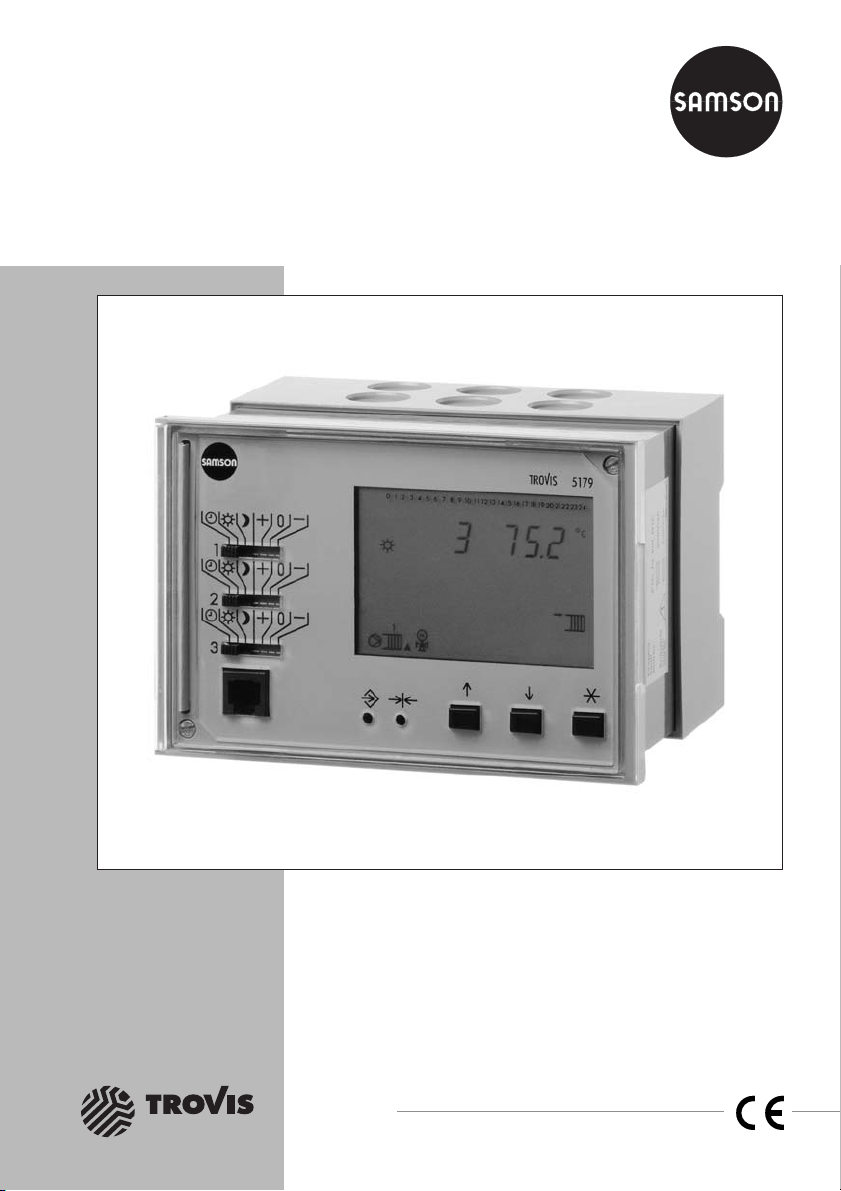
Automation System TROVIS 5100
District Heating Controller
TROVIS 5179
Electronics from SAMSON
Mounting and
Operating Instructions
EB 5179 EN
®
Firmware version 1.2x
Edition August 2005
Page 2
Disclaimer of liability
Disclaimer of liability
We are constantly developing our products and therefore, reserve the right to change the
product or the information contained in this document at any time without notice.
We do not assume any liability for the accuracy or completeness of these mounting and
operating instructions. Moreover, we do not guaranteethat thebuyer can use the product for an
intended purpose. SAMSON rejects any liability for claims by the buyer, especially claims for
compensation including lost profits or any other financial loss, except the damage was caused
intentionally or by gross negligence. If an essential term of the contract is breached by
negligence, SAMSON’s liability is limited to the foreseeable damage.
Safety instructions
The device may only be assembled, started up or operated by trained and
4
experienced personnel familiar with the product. Proper shipping and
appropriate storage are assumed.
The controller has been designed for use in electrical power systems. For
4
wiring and maintenance, you are required to observe the relevant safety
regulations.
2 EB 5179 EN
Page 3

Contents
Contents
1 Operation . . . . . . . . . . . . . . . . . . . . . . . . . . . . . . . 6
1.1 Operating elements. . . . . . . . . . . . . . . . . . . . . . . . . . . 6
1.1.1 Operating keys . . . . . . . . . . . . . . . . . . . . . . . . . . . . . 6
1.1.2 Operating switches . . . . . . . . . . . . . . . . . . . . . . . . . . . 7
1.2 Operating modes. . . . . . . . . . . . . . . . . . . . . . . . . . . . 8
1.3 Display. . . . . . . . . . . . . . . . . . . . . . . . . . . . . . . . . 9
1.4 Displaying data . . . . . . . . . . . . . . . . . . . . . . . . . . . . 10
1.5 Setting the controller time . . . . . . . . . . . . . . . . . . . . . . . 11
1.6 Setting the times-of-use . . . . . . . . . . . . . . . . . . . . . . . . 13
1.6.1 Copying the times-of-use . . . . . . . . . . . . . . . . . . . . . . . 15
1.6.2 Entering public holidays . . . . . . . . . . . . . . . . . . . . . . . . 16
1.6.3 Entering vacation periods . . . . . . . . . . . . . . . . . . . . . . . 18
2 Start-up. . . . . . . . . . . . . . . . . . . . . . . . . . . . . . . . 20
2.1 Setting the system code number . . . . . . . . . . . . . . . . . . . . 20
2.2 Activating and deactivating functions. . . . . . . . . . . . . . . . . . 21
2.3 Changing parameters . . . . . . . . . . . . . . . . . . . . . . . . . 23
2.3.1 Enter key number . . . . . . . . . . . . . . . . . . . . . . . . . . . 24
2.4 Configuring universal inputs . . . . . . . . . . . . . . . . . . . . . . 24
2.5 Calibrating sensors . . . . . . . . . . . . . . . . . . . . . . . . . . 24
2.6 Resetting to default values . . . . . . . . . . . . . . . . . . . . . . . 26
3 Manual operation . . . . . . . . . . . . . . . . . . . . . . . . . . . 27
4 Systems. . . . . . . . . . . . . . . . . . . . . . . . . . . . . . . . 28
5 Functions of the heating circuit . . . . . . . . . . . . . . . . . . . . 38
5.1 Functioning principle . . . . . . . . . . . . . . . . . . . . . . . . . 38
5.2 Weather-compensated control . . . . . . . . . . . . . . . . . . . . . 38
5.2.1 Gradient characteristic . . . . . . . . . . . . . . . . . . . . . . . . 39
5.2.2 4-point characteristic . . . . . . . . . . . . . . . . . . . . . . . . . 39
5.3 Fixed set point control . . . . . . . . . . . . . . . . . . . . . . . . . 41
5.4 Differential temperature control using variable weighting factors. . . . . 41
5.5 Deactivation depending on outdoor temperature . . . . . . . . . . . . 42
5.5.1 OT deactivation value in rated operation . . . . . . . . . . . . . . . . 42
5.5.2 OT deactivation value in reduced operation . . . . . . . . . . . . . . 42
5.5.3 OT activation value in rated operation . . . . . . . . . . . . . . . . . 43
5.5.4 Summer mode. . . . . . . . . . . . . . . . . . . . . . . . . . . . . 43
5.6 Delayed outdoor temperature adaptation. . . . . . . . . . . . . . . . 44
5.7 Outdoor temperature-dependent advance heating . . . . . . . . . . . 44
EB 5179 EN 3
Page 4

Contents
5.8 Remote operation . . . . . . . . . . . . . . . . . . . . . . . . . . . 45
5.9 Optimization with room sensor. . . . . . . . . . . . . . . . . . . . . 45
5.10 Flash adaptation . . . . . . . . . . . . . . . . . . . . . . . . . . . 47
5.11 Adaptation . . . . . . . . . . . . . . . . . . . . . . . . . . . . . . 47
5.12 Room temperature-dependent control . . . . . . . . . . . . . . . . . 48
5.13 Pump management . . . . . . . . . . . . . . . . . . . . . . . . . . 49
5.14 Releasing the heating circuit . . . . . . . . . . . . . . . . . . . . . . 50
5.15 Position feedback in pre-control circuit . . . . . . . . . . . . . . . . . 50
6 Functions of the DHW circuit. . . . . . . . . . . . . . . . . . . . . . 51
6.1 DHW heating in the storage tank charging system . . . . . . . . . . . 51
6.2 DHW heating in the storage tank system . . . . . . . . . . . . . . . . 53
6.3 Priority operation . . . . . . . . . . . . . . . . . . . . . . . . . . . 55
6.3.1 Reverse control . . . . . . . . . . . . . . . . . . . . . . . . . . . . 55
6.3.2 Set-back operation . . . . . . . . . . . . . . . . . . . . . . . . . . 56
6.4 Forced charging of the DHW storage tank . . . . . . . . . . . . . . . 56
6.5 Thermal disinfection of the DHW storage tank . . . . . . . . . . . . . 56
7 System-wide functions . . . . . . . . . . . . . . . . . . . . . . . . 58
7.1 Automatic summer time/winter time changeover . . . . . . . . . . . . 58
7.2 Frost protection . . . . . . . . . . . . . . . . . . . . . . . . . . . . 58
7.3 Forced operation of the pumps. . . . . . . . . . . . . . . . . . . . . 58
7.4 Return flow temperature limitation . . . . . . . . . . . . . . . . . . . 58
7.5 Condensate accumulation control . . . . . . . . . . . . . . . . . . . 60
7.6 Compensating for time delays . . . . . . . . . . . . . . . . . . . . . 60
7.7 Three-step control . . . . . . . . . . . . . . . . . . . . . . . . . . . 61
7.8 On/off control . . . . . . . . . . . . . . . . . . . . . . . . . . . . 62
7.9 Continuous-action control . . . . . . . . . . . . . . . . . . . . . . . 62
7.10 Forwarding the outdoor temperature . . . . . . . . . . . . . . . . . . 63
7.11 Flow rate/capacity limitation over a pulse input. . . . . . . . . . . . . 63
7.12 Locking manual level . . . . . . . . . . . . . . . . . . . . . . . . . 65
8 Operational faults . . . . . . . . . . . . . . . . . . . . . . . . . . 66
8.1 Error list/sensor failure . . . . . . . . . . . . . . . . . . . . . . . . 66
8.2 Collective error alarm . . . . . . . . . . . . . . . . . . . . . . . . . 67
8.3 Temperature monitoring . . . . . . . . . . . . . . . . . . . . . . . . 69
8.4 Monitoring the input terminals for limit violations . . . . . . . . . . . . 70
8.5 Error status register . . . . . . . . . . . . . . . . . . . . . . . . . . 71
4 EB 5179 EN
Page 5

Contents
8.6 Error alarms . . . . . . . . . . . . . . . . . . . . . . . . . . . . . 72
8.6.1 Sending text message in case of a fault alarm . . . . . . . . . . . . . 73
8.6.2 Sending fax in case of a fault alarm . . . . . . . . . . . . . . . . . . 73
9 Communication . . . . . . . . . . . . . . . . . . . . . . . . . . . . 75
9.1 RS-232-C system bus interface . . . . . . . . . . . . . . . . . . . . 76
9.2 RS-232/RS-485 system bus interface (for four-wire bus) in combination with
cable converters . . . . . . . . . . . . . . . . . . . . . . . . . . . . . . . . . . . 77
9.3 Description of communication parameters to be adjusted . . . . . . . . 78
9.4 Meter bus interface . . . . . . . . . . . . . . . . . . . . . . . . . . 80
9.4.1 Activating the meter bus . . . . . . . . . . . . . . . . . . . . . . . . 80
9.4.2 Flow rate/capacity limitation using meter bus. . . . . . . . . . . . . . 81
9.5 LON communication. . . . . . . . . . . . . . . . . . . . . . . . . . 83
9.6 Requesting/processing an external demand . . . . . . . . . . . . . . 84
9.7 Sending outdoor temperatures and controller time . . . . . . . . . . . 85
10 Installation . . . . . . . . . . . . . . . . . . . . . . . . . . . . . . 87
11 Electrical connection. . . . . . . . . . . . . . . . . . . . . . . . . . 89
12 Appendix. . . . . . . . . . . . . . . . . . . . . . . . . . . . . . . 96
12.1 Function block lists. . . . . . . . . . . . . . . . . . . . . . . . . . . 96
12.2 Parameter list . . . . . . . . . . . . . . . . . . . . . . . . . . . . 107
12.3 Display . . . . . . . . . . . . . . . . . . . . . . . . . . . . . . . 121
12.4 Sensor resistance tables . . . . . . . . . . . . . . . . . . . . . . . 128
12.5 Technical data . . . . . . . . . . . . . . . . . . . . . . . . . . . . 129
12.6 Customer data . . . . . . . . . . . . . . . . . . . . . . . . . . . . 130
EB 5179 EN 5
Page 6

Operation
1 Operation
The controller is ready for use with the temperatures and operating schedules preset by the
manufacturer.
On start-up, the current time and date need to be set at the controller (–> section 1.5).
1.1 Operating elements
The operating controls are located in the front panel of the controller and protected by a Plexi
glas door.
1.1.1 Operating keys
Changeover key
Press to switch between operating level and configuration/parameter level
Reset key
Press to reset accessible parameters to their default settings; the controller
must be in the parameter level
Arrow keys
– To scroll within levels
– To change values
Enter key
– To access levels
– Access parameters and functions to edit them
– Confirm settings
– Display set points in info level
-
6 EB 5179 EN
Page 7
Operation
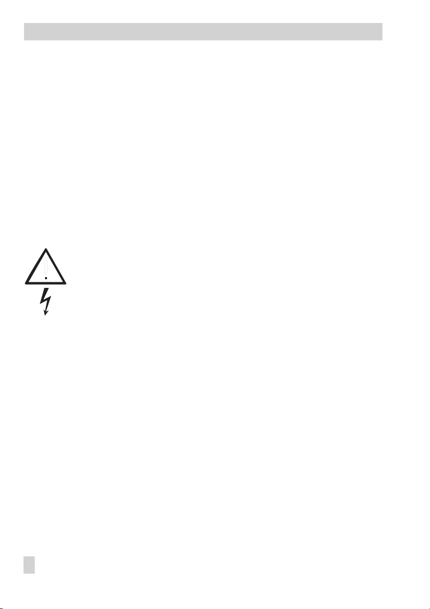
1.1.2 Operating switches
Heating circuit mode selector switch
Automatic mode with switchover between
rated operation and reduced operation
Rated operation
Reduced operation
Manual operation: Control valve opens - stationary - closes
(for on/off control: + ON, 0 OFF)
DHW circuit mode selector switch
The operating mode icon stickers are included in the scope of delivery and can be stuck on
the front above the mode selector switch for control circuit 2 (middle), if required.
Automatic mode
Rated operation
DHW heating OFF
Manual operation: Control valve opens - stationary - closes
(for on/off control: + ON, 0 OFF)
Note!
In manual mode, frost protection is not guaranteed.
EB 5179 EN 7
Page 8
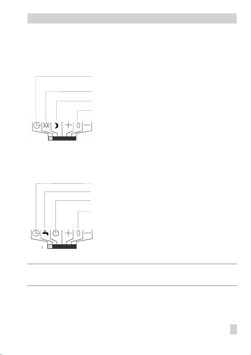
Operation
The assignment of the control circuits to the mode selector switches depends on the system
code number (Anl):
System
(Anl)
Top Middle Bottom
1 Heating circuit 1 Heating circuit 2 Pre-control circuit
2 Heating circuit 1 DHW heating Heating circuit 2
3 Heating circuit 1 Heating circuit 2 Heating circuit 3/Pre-control
4 Heating circuit 1 DHW heating Pre-control circuit
5 Heating circuit 1 DHW heating Heating circuit 2/Pre-control
6 Heating circuit 1 Heating circuit 2 Heating circuit 3
7 Heating circuit 1 DHW heating Pre-control circuit
8 Heating circuit 1 DHW heating Heating circuit 2/Pre-control
9 Heating circuit 1 DHW heating Heating circuit 2
10 Heating circuit 1 DHW heating Heating circuit 2
Mode selector switch
circuit
circuit
circuit
1.2 Operating modes
Day mode (rated operation)
Regardless ofthe programmed times-of-use and summer mode,the set points relevant for rated
operation are used by the controller.
Night mode (reduced operation)
Regardless of the programmed times-of-use, the set points relevant for reduced operation are
used by the controller.
Automatic mode
During the programmed times-of-use, the controller works in rated operation. Outside these
times-of-use, the controller is in reduced operation, unless control operation is deactivated de
pending on the outdoor temperature. The controller switches automatically between both oper
ating modes.
Manual operation+ 0 –
Valves and pumps can be controlled manually.
8 EB 5179 EN
-
-
Page 9
1.3 Display
Operation
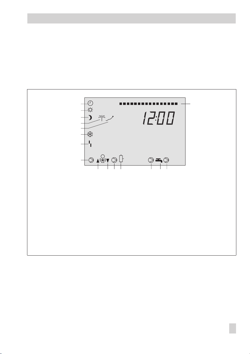
During operation, the display indicates the current time as well as informationabout the opera
tion of the controller. The times-of-use are represented by black squares below the row of num
bers at the top of the display. Icons indicate the operating status of the controller.
The controller status can be displayed in the operating level (InF level) (–> section 1.4).
1
2
3
4
5
6
7
8
1 Automatic operation
2 Day mode
(rated operation)
3 Night mode
(reduced operation)
4 Vacation mode
5 Public holiday mode
6 Frost protection
7 Malfunction
1
1
9
10 11 12 1413 15
8 Circulation pump RK1–3
9 Valve RK1–3 or
Primary valve: OPEN or
DHW: OPEN
10 Valve RK1–3 or
Primary valve: CLOSED
or DHW: CLOSED
11 Storage tank charging
pump SLP
10 11 12 13 14 15 16 17 18 19123456789 0212223240
452
16
12 DHW storage tank
13 Circulation pump ZP
14 DHW demand
15 Exchanger charging pump
TLP
16 Time-of-use
-
-
Fig. 1 · Icons
EB 5179 EN 9
Page 10

Operation
1.4 Displaying data
Measured values, set points, times-of-use, public holidays and vacation periods can be re
trieved and displayed in the
section 11.4.
InF1: Heating circuit 1
4
InF2: Heating circuit 2
4
InF3: Heating circuit 3
4
InF4: DHW heating
4
InF5: Primary control circuit
4
InF6: Does not exist
4
InF7: LON communication
4
InF8: Error status register/sensor failure
4
InF9: Communication
4
PU: Pumps, manual level
4
bIn-E: Binary inputs and outputs
4
Error: Alarms
4
Proceed as follows:
Select information level (–> Fig. 10 on page 141).
Confirm information level.
Select value you want to change.
Compare the set point/limit value and the actual value.
Press keys simultaneously:
to switch to the operating level.
InF1toInF9
information levels. The various displays are listed in
-
10 EB 5179 EN
Page 11
Operation
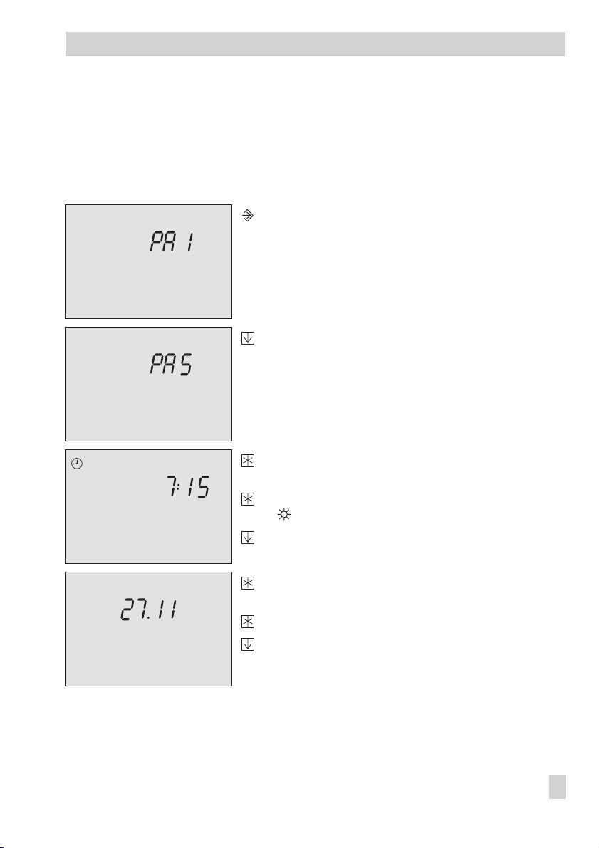
1.5 Setting the controller time
The current time and date need to be set immediately after start-up and after a power failure
lasting longer than 24 hours.
Proceed as follows:
9876543210
242322212019181716151413121110
Switch to configuration and parameter level.
Display:
PA1
9876543210
9876543210
242322212019181716151413121110
242322212019181716151413121110
Select PA5 parameter level.
Open PA5 parameter level.
Display: Controller time
Activate editing mode for the controller time
blinks.
Change controller time.
9876543210
242322212019181716151413121110
Confirm controller time.
Display: Date (day.month)
Activate editing mode for the controller date.
Change date setting.
EB 5179 EN 11
Page 12

Operation
9876543210
242322212019181716151413121110
Confirm date.
Display: Year.
Activate editing mode for the controller year.
Change year setting.
Confirm year.
Exit PA5 parameter level.
Return to the operating level.
Note!
The controller automatically returns to the operating level if the keys are left unpressed for two
minutes.
12 EB 5179 EN
Page 13
Operation
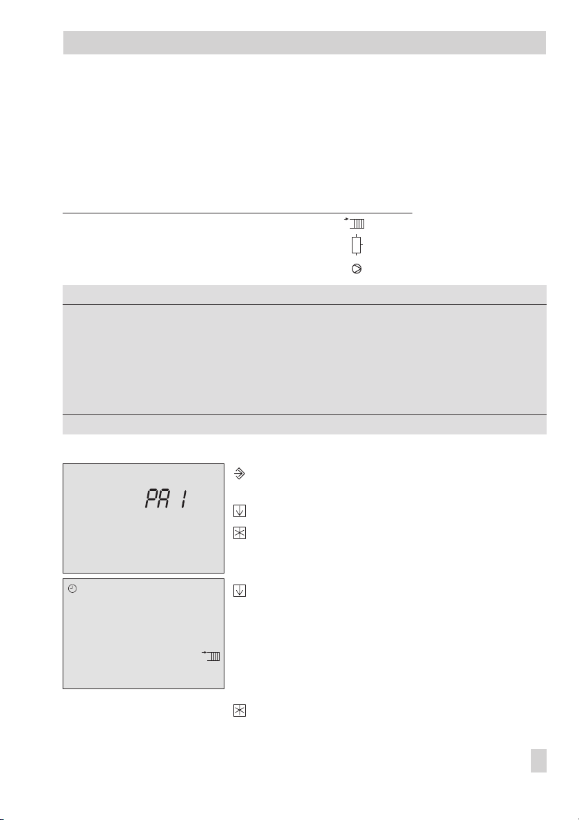
1.6 Setting the times-of-use
Two times-of-use can be set for each day of the week. If just one time-of-use is required, the start
and stop times of the second time-of-use must be programmed to identical times. The time
schedules for the three heating circuits, DHW heating and the circulation pump can be read
over Modbus. Pump circuits are treated as mixer circuits.
Time schedule Parameter level Icon
Heating circuit 1 to 3 PA1 to PA3
DHW heating PA4
Circulation pump PA4
Parameters
Period/day 1–7 1–7, 1, 2, 3, 4, 5, 6, 7 with 1–7 = every day,
Start first time-of-use 07:00 0:00 to 24:00h; in steps of 30 minutes
Stop first time-of-use 12:00 0:00 to 24:00h; in steps of 30 minutes
Start second time-of-use 12:00 0:00 to 24:00h; in steps of 30 minutes
Stop second time-of-use 22:00 0:00 to 24:00h; in steps of 30 minutes
* Default settings (WE) valid for heating circuits 1 to 3
WE* Range of values
1 = Monday, 2 = Tuesday, ..., 7 = Sunday
Proceed as follows:
9876543210
0 1 2 3 4 5 6 7 8 9 10 11 12 13 14 15 16 17 18 19 20 21 22 23 24
242322212019181716151413121110
Switch to configuration and parameter level.
Display:
PA1
Select parameter level.
Open parameter level.
Select datapoint for times-of-use.
EB 5179 EN 13
Page 14
Operation
9876543210
242322212019181716151413121110
Activate editing mode for times-of-use.
Display:
1–7
Select period/day for which the times-of-use are to
be valid:
1–7 = every day,
1 = Monday, 2 = Tuesday, ..., 7 = Sunday
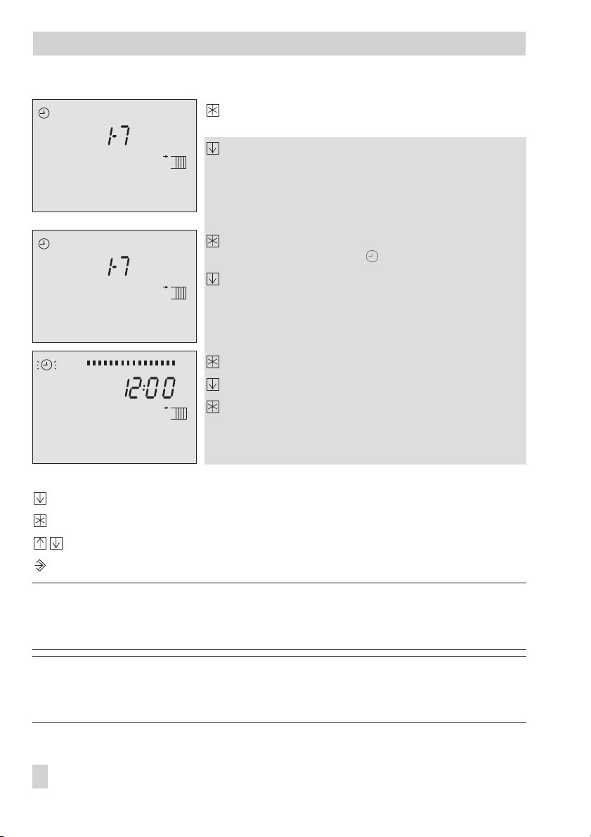
9876543210
242322212019181716151413121110
Activate editing mode for period/day.
START
Display shows:
; blinks
Edit start time (steps of 30 minutes).
9876543210
242322212019181716151413121110
Confirm start time. Display shows:
STOP
Edit stop time (steps of 30 minutes).
STOP
Confirm stop time.
Display shows:
START
The second time-of-use is set like the first time-of-use.
To set the times-of-use for each day, repeat the instructions in the fields highlighted in gray.
End
Select
on the display.
Exit the datapoint for times-of-use.
Exit the parameter level.
Return to the operating level.
Note!
Do not use the 1–7 datapoints to check the programmed times-of-use. Otherwise, the
times-of-use are reset to their default settings.
Note!
The controller automatically returns to the operating level if the keys are left unpressed for two
minutes.
14 EB 5179 EN
Page 15

Operation
1.6.1 Copying the times-of-use
The times-of-use of heating circuit 1 (2) can be copied and used for heating circuit 2 (3).
Copy function Parameter level Icon
HK1 –> HK2 PA1
HK2 –> HK3 PA2
Proceed as follows:
Switch to configuration and parameter level.
Display:
Select parameter level.
Open parameter level.
Select “COPY_“ data point.
Open copy program.
The display blinks.
Copy the times-of-use.
Select
Exit the parameter level.
Return to the operating level.
PA1
End
on the display.
COPY2
COPY3
EB 5179 EN 15
Page 16
Operation
1.6.2 Entering public holidays
On public holidays, the times-of-use specified for Sunday apply. A maximum of 20 public holi
days may be entered.
Parameters
Public holidays f. heating circuit 1 – PA1 / 01.01 to 31.12
Public holidays f. heating circuit 2 – PA2 / 01.01 to 31.12
Public holidays f. heating circuit 3 – PA3 / 01.01 to 31.12
WE Level / Range of values
Note!
The programmed public holidays and vacations of any heating circuit (HK1, HK2 or HK3) ap
ply with the setting Co4 -> Fb12 = ON , select 1, 2 or 3 also for the DHW heating.
Proceed as follows: Switch to configuration and parameter level.
Display:
PA1
Select parameter level.
Open parameter level.
0 1 2 3 4 5 6 7 8 9 10 11 12 13 14 15 16 17 18 19 20 21 22 23 24
Select datapoint for public holidays.
Display shows:
Open data point for public holidays.
– – – –
If applicable, select
.
Activate editing mode for public holiday.
blinks.
Edit public holiday
Confirm public holiday.
––––
To enter additional public holidays, re-select
(between 31.12 and 01.01) and repeat the
steps in the fields highlighted in gray.
Exit the parameter level.
Return to the operating level.
-
-
16 EB 5179 EN
Page 17

Operation
Note!
Public holidays that are not assigned to a specific date should be deleted by the end of the year
so that they are not carried on into the following year.
Deleting a public holiday:
Select the holiday you wish to delete in the datapoint for public holidays.
Confirm selection.
Select
– – – –
.
Delete the public holiday.
Note!
The controller automatically returns to the operating level if the keys are left unpressed for two
minutes.
EB 5179 EN 17
Page 18
Operation
1.6.3 Entering vacation periods
During vacation periods, the controller constantly remains in the reduced operating mode. The
system is monitored for frost. A maximum of 10 vacation periods can be entered.
Parameters
Vacation period for heating circuit 1 – PA1 / 01.01 to 31.12
Vacation period for heating circuit 2 – PA2 / 01.01 to 31.12
Vacation period for heating circuit 3 – PA3 / 01.01 to 31.12
Note!
The programmed public holidays and vacations of any heating circuit (HK1, HK2 or HK3) ap
ply with the setting Co4 -> Fb12 = ON , select 1, 2 or 3 also for the DHW heating.
Proceed as follows: Switch to configuration and parameter level.
0 1 2 3 4 5 6 7 8 9 10 11 12 13 14 15 16 17 18 19 20 21 22 23 24
To enter additional vacation periods, re-select
the steps in the fields highlighted in gray.
Exit the parameter level.
WE Level / Range of values
Display:
PA1
Select parameter level.
Open parameter level.
Select datapoint for vacation periods.
Display shows:
Open datapoint for vacation periods.
Display shows
If applicable, select
: START
– – – –
.
Activate editing mode for vacation periods.
blinks.
Set start date of vacation period.
Confirm start date of the vacation period.
Display shows:
STOP
Set end of vacation period.
Confirm end of the vacation period.
––––
(between 31.12 and 01.01) and repeat
-
18 EB 5179 EN
Page 19

Operation
Return to the operating level.
Note!
Vacation periods that are not assigned to a specific date should be deleted by the end of the
year so that they are not carried on into the following year.
Deleting vacation periods:
Select the vacation period you wish to delete in the datapoint for vacation periods.
Confirm selection.
Select
– – – –
.
Delete vacation period.
Note!
The controller automatically returns to the operating level if the keys are left unpressed for two
minutes.
EB 5179 EN 19
Page 20

Start-up
2 Start-up
2.1 Setting the system code number
10 different hydraulic schematics are available. Each system configuration is represented by a
system code number. The different schematics are dealt with in section 4. Available controller
functions are described in sections 5, 6 and 7.
Changing the system code number resets previously adjusted function blocks to their default set
tings (WE).
The system code number is set in the configuration level.
Proceed as follows:
Switch to configuration and parameter level.
Display shows:
Select
Anl
Activate editing mode for the system code number.
Anl
blinks on the display.
Edit system code number.
Confirm system code number.
Display shows:
Return to the operating level.
PA1
_ on the display.
Co1
-
Note!
The controller automatically returns to the operating level if the keys are left unpressed for two
minutes.
20 EB 5179 EN
Page 21

Start-up
2.2 Activating and deactivating functions
A function is activated or deactivated in the associated function block. The numbers 0 to 24 in
the top row of the display represent the respective function block numbers. When a configura
tion level is opened, the activated function blocks are indicated by a black square on the
right-hand side below the function block number. For more details on function blocks, refer to
section 12.1.
The functions are grouped by topics:
Co1: Heating circuit 1
4
Co2: Heating circuit 2
4
Co3: Heating circuit 3
4
Co4: DHW heating
4
Co5: System-wide functions
4
Co6: Sensor initialization
4
Co7: LON communication
4
Co8: Error initialization
4
Co9: Communication
4
Proceed as follows:
Switch to configuration and parameter level.
Display shows:
Select configuration level.
Open configuration level.
Select function block.
Activate editing mode for the function block.
Fb_ blinks on the display.
0 0 0 0
If
section 2.3.1
Activate the function block (Fb = ON).
An activated function block is indicated by a black square below (right) the function
block number in the top row of the controller display.
or:
Deactivate the function block (Fb = OFF).
PA1
appears on the display, the key number needs to be entered first. Refer to
-
EB 5179 EN 21
Page 22

Start-up
Confirm settings.
If the function block is not closed, further function block parameters can be adjusted.
Proceed as follows:
Make the desired changes and confirm.
If applicable, the next function block parameter is displayed.
Confirm all parameters to exit the opened function block.
To adjust additional function blocks, repeat the steps in the fields highlighted in gray.
Exit configuration level.
Return to the operating level.
Note!
The controller automatically returns to the operating level if the keys are left unpressed for two
minutes.
22 EB 5179 EN
Page 23

Start-up
2.3 Changing parameters
Depending on the set system code number and the activated functions, not all parameters listed
in the parameter list in the Appendix (–> section 12.2) might be available.
The parameters are grouped by topics:
PA1: Heating circuit 1
4
PA2: Heating circuit 2
4
PA3: Heating circuit 3
4
PA4: DHW heating
4
PA5: System-wide parameters
4
PA6: Does not exist
4
PA7: LON communication
4
PA8: Does not exist
4
PA9: Communication
4
Proceed as follows:
Switch to configuration and parameter level.
Display shows:
Select parameter level.
Open parameter level.
Select parameter.
Activate editing mode for the parameter.
Edit the parameter.
Confirm the parameter setting.
To adjust additional parameters, repeat the steps in the fields highlighted in gray.
Exit parameter level.
Return to the operating level.
PA1
Note!
The controller automatically returns to the operating level if the keys are left unpressed for two
minutes.
EB 5179 EN 23
Page 24

Start-up
2.3.1 Enter key number
Some functions are protected against unintentional or unauthorized access. These functions can
only be activated or deactivated after the valid key number has been entered. The valid key
number for initial start-up can be found on page 137. To avoid unauthorized use of the key
number, remove the page or make the key number unreadable.
Proceed as follows:
0 0 0 0
The key number remains active for approx. 10 minutes.
blinks on the display.
Set valid key number.
Confirm key number.
When the correct key number is entered, the function block that is to be changed
blinks on the display.
On entering an incorrect key number, the controllers switches to the next configuration
level.
2.4 Configuring universal inputs
The connected sensors are calibrated in Co6 configuration level.
The following applies:
Co6 -> Fb00 = ON: Pt 100/Pt 1000 sensors (default setting)
4
Co6 -> Fb00 = OFF: Pt 100/PTC sensors
4
The resistance values of the sensors can be found on page 128.
Each universal input can be configured separately.
The following inputs Ni 200/1000, PTC, NTC, Pt 100/1000, (0/4...20) mA, (0–10 V) can be
configured as function block parameters.
The function blocks 01 to 17 correspond to the binary inputs BE1 to BE17 in the terminal wiring
plan (page 92 onwards).
The function block for the required sensor is activated and the function block parameter selected
which corresponds to the type of input signal.
2.5 Calibrating sensors
If the temperature values displayed at the controller differ from the actual temperatures, the
measured values of all connected sensors can be changed or readjusted. To calibrate a sensor,
the currently displayed sensor value must be changed such that it matches the temperature (ref
24 EB 5179 EN
-
Page 25

Start-up
erence temperature) measured directly at the point of measurement. Sensor calibration is to be
activated in Co6 via function block Fb23.
Proceed as follows:
Switch to configuration and parameter level.
Display shows:
PA1
Select Co6 level.
Open Co6 level. Display shows:
Fb00
Select function block Fb23.
Confirm selection. Display shows:
0 0 0 0
Enter and confirm key number.
Fb23 blinks on the display.
Activate editing mode for function block.
Activate function block.
Start sensor calibration.
Select the function block for the sensor that you want to calibrate:
The function blocks Fb01 to Fb17 correspond to the inputs in the terminal wiring plan
(page 92 onwards) e.g. Fb02 = BE2
Activate editing mode for function block.
Fb_ blinks on the display.
Display measured value.
Activate editing mode for measured value.
Measured value blinks on the display.
Correct measured temperature. Read the actual temperature directly from the ther
mometer at the point of measurement and enter this value as the reference tempera
-
-
ture.
Confirm corrected measured temperature.
Additional sensors are calibrated similarly.
End
Select
.
Exit configuration level.
Return to the operating level.
EB 5179 EN 25
Page 26

Start-up
Note!
The sensor values adjusted are not reset by the Loading default settings function.
2.6 Resetting to default values
All parameters and function blocks from any parameter level can be reset to their default set
tings (WE).
Proceed as follows:
Reset to default settings.
Function blocks and parameters are reset to their default settings (WE).
Note!
When the key number is active, thefunction blocksprotected bythe key number are also reset to
their default settings.
The controller isready foroperation with its default settings. You just need to set the correctdate
and current time.
-
26 EB 5179 EN
Page 27

Manual operation
3 Manual operation
Switch to manual mode to configure all outputs (see wiring diagram in section 11).
Proceed as follows:
Position all selector mode switches to +, 0 or –.
Select
PU
pump manual level.
Open pump manual level.
Select pump PU1 to PU5:
PU1: BA11
PU2: BA12
PU3: BA13
PU4: BA14
PU5: BA15
Confirm pump selection.
The display blinks.
Activate output:
Deactivate output:
Confirm setting.
The modified values remain active as long as the controller is in manual mode.
Move slide switch from 0, + or –.
Exit manual level.
Note!
In manual mode, frost protection is not guaranteed.
EB 5179 EN 27
Page 28

Systems
4 Systems
There are 10 hydraulic schematics.
System code number (Anl)
Heating Outdoor temperature compensated flow temperature
Number of heating circuits 2231231222
No. of heating circuits w. mixing valve 2221131122
DHW heating • •• ••••
From the primary circuit •••
From the secondary circuit ••• •
12345678910
control with variable return flow temperature limitation
28 EB 5179 EN
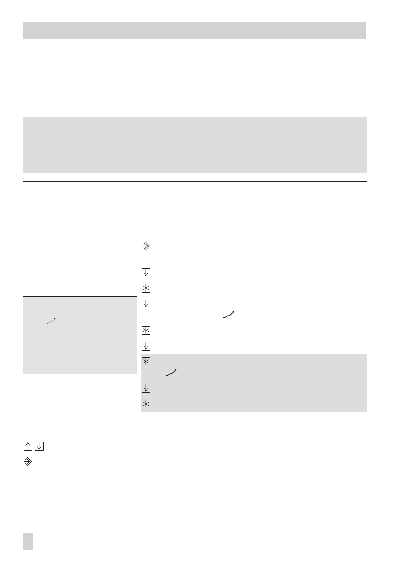
Page 29
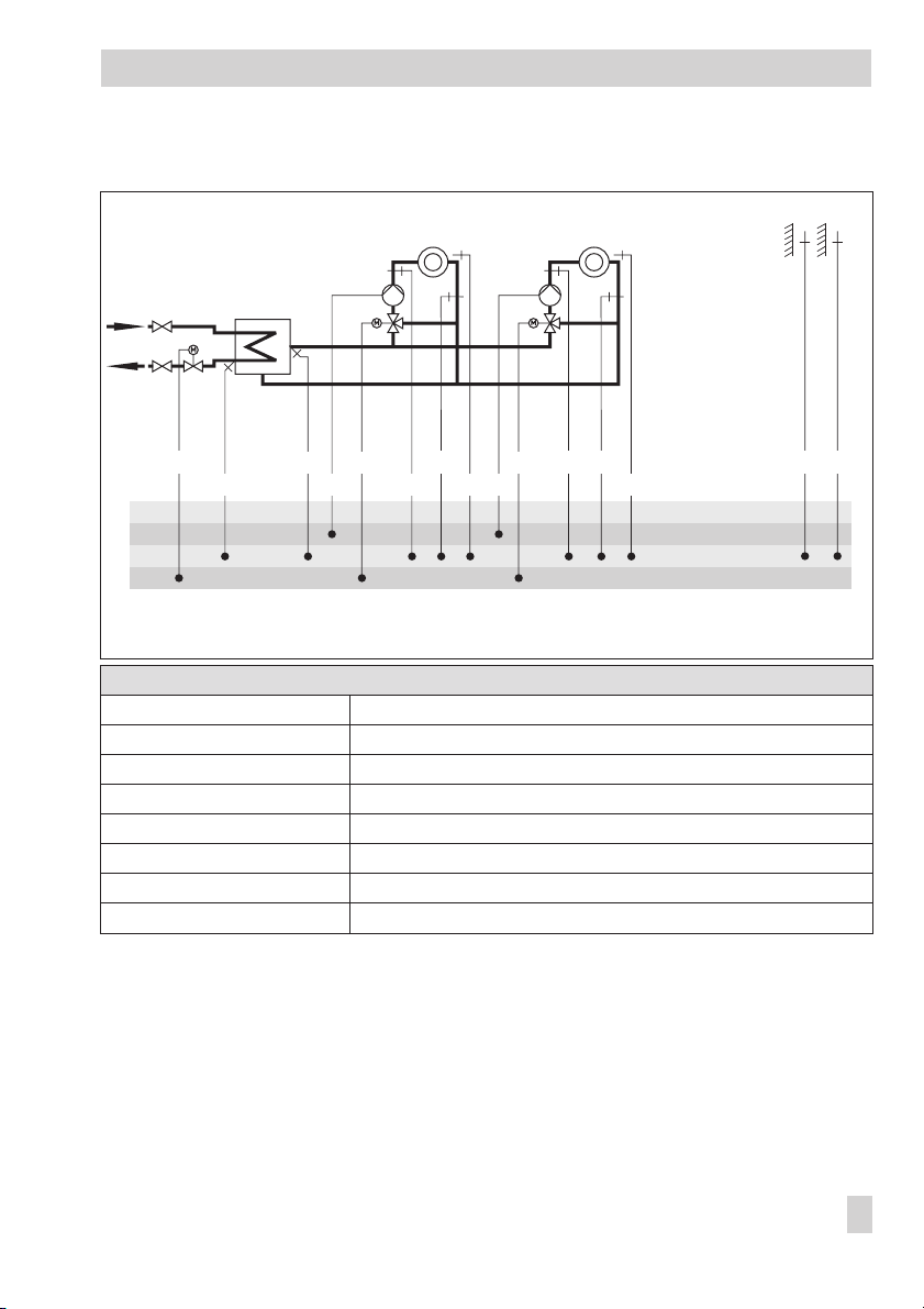
System Anl 1
Systems
BE
BA
AE
RK
RK
prim
VF
sek
HK1
UP1 UP2
RK
FW
RüF
RüF1 RK
RF1VF1
HK2
VF2
RüF2
RF2
Default setting
Co1 -> Fb00 = OFF (without RF1)
Co1 -> Fb01 = OFF (without RüF1)
Co1 -> Fb02 = ON (with AF1)
Co2 -> Fb00 = OFF (without RF2)
Co2 -> Fb01 = OFF (without RüF2)
Co2 -> Fb02 = OFF (without AF2)
Co5 -> Fb00 = ON (with VFsek)
Co5 -> Fb01 = ON (with RüFprim)
AF2AF1
EB 5179 EN 29
Page 30
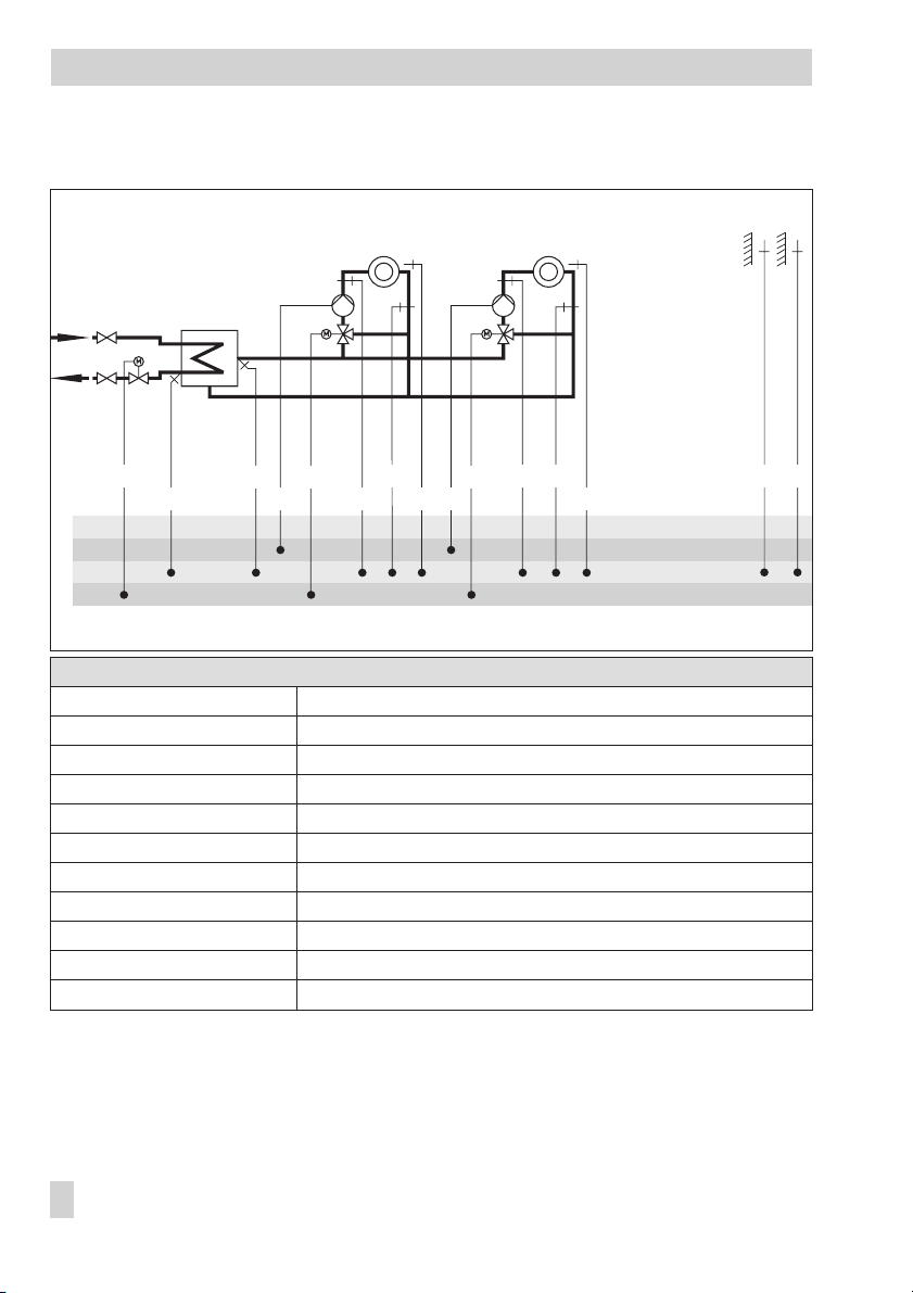
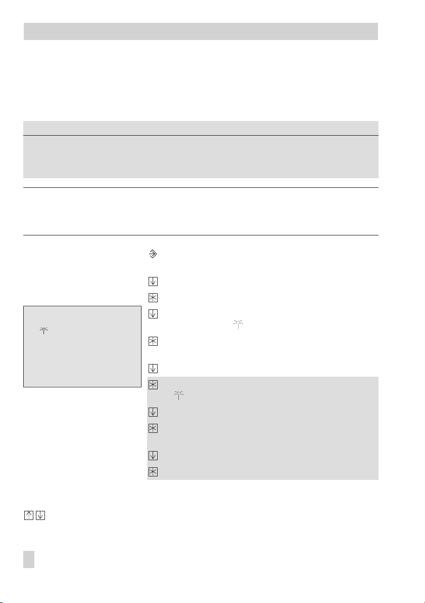
Systems
System Anl 2
BE
BA
AE
RK
RK
FW
RüF
prim
RK
VF
sek
HK1
UP1 UP2
RüF1 RK
RF1VF1
HK2
VF2
RüF2
RF2
Default setting
Co1 -> Fb00 = OFF (without RF1)
Co1 -> Fb01 = OFF (without RüF1)
Co1 -> Fb02 = ON (with AF1)
Co2 -> Fb00 = OFF (without RF2)
Co2 -> Fb01 = OFF (without RüF2)
Co2 -> Fb02 = OFF (without AF2)
Co4 -> Fb00 = ON (with SF1)
Co4 -> Fb01 = ON (with SF2)
Co4 -> Fb03 = ON (with VFS, with VFT)
Co5 -> Fb00 = ON (with VFsek)
Co5 -> Fb01 = ON (with RüFprim)
AF2AF1
30 EB 5179 EN
Page 31

System Anl 3
Systems
prim
VF
RK
sek
UP1 UP2
HK1
RüF1 RK
RüF2
VF2 VF3
HK2
RF1VF1
RF2 UP3
BE
BA
AE
RK
RK
FW
RüF
Default setting
Co1 -> Fb00 = OFF (without RF1)*
Co1 -> Fb01 = OFF (without RüF1)
Co1 -> Fb02 = ON (with AF1)
Co2 -> Fb00 = OFF (without RF2)*
Co2 -> Fb01 = OFF (without RüF2)
Co2 -> Fb02 = OFF (without AF2)
Co5 -> Fb00 = ON (with VFsek)
Co5 -> Fb01 = ON (with RüFprim)
* Only for optimization and temperature reading
AF2AF1
EB 5179 EN 31
Page 32

Systems
System Anl 4
WW
KW
SLP
SF2
ZP
BE
BA
AE
RK
RK
FW
RüF
prim
RK
VF
sek
HK1
UP1
RüF1 RK
RF1VF1
TW
VFT
RüFTW
TLP
VFS
Default setting
Co1 -> Fb00 = OFF (without RF1)
Co1 -> Fb01 = OFF (without RüF1)
Co1 -> Fb02 = ON (with AF1)
Co4 -> Fb00 = ON (with SF1)
Co4 -> Fb01 = ON (with SF2)
Co4 -> Fb02 = OFF (without RüFTW)
Co4 -> Fb03 = ON (with VFS, with VFT)
Co5 -> Fb00 = ON (with VFsek)
Co5 -> Fb01 = ON (with RüFprim)
Set Co4 -> Fb11 = ON if the instrumentation represented by the broken line is required.
AF1
SF1
32 EB 5179 EN
Page 33

System Anl 5
Systems
WW
KW
SLP
SF2
ZP
BE
BA
AE
RK
RK
FW
RüF
prim
RK
VF
sek
UP1
RüF1 RK
HK1
RF1VF1
UP2
VF2
TW
VFT
RüFTW
TLP
VFS
Default setting
Co1 -> Fb00 = OFF (without RF1)*
Co1 -> Fb01 = OFF (without RüF1)
Co1 -> Fb02 = ON (with AF1)
Co4 -> Fb00 = ON (with SF1)
Co4 -> Fb01 = ON (with SF2)
Co4 -> Fb02 = OFF (without RüFTW)
Co4 -> Fb03 = ON (with VFS, with VFT)
Co5 -> Fb00 = ON (with VFsek)
Co5 -> Fb01 = ON (with RüFprim)
* Only for optimization and temperature reading
Set Co4 -> Fb11 = ON if the instrumentation represented by the broken line is required.
AF1
SF1
EB 5179 EN 33
Page 34

Systems
System Anl 6
BE
BA
AE
RK
RK
VF
UP1
sek
HK1
RüF1
RüF2
VF2
UP2
RF1VF1
RK
HK2
RF2
UP3
VF3
RK
HK3
Default setting
Co1 -> Fb00 = OFF (without RF1)
Co1 -> Fb01 = OFF (without RüF1)
Co1 -> Fb02 = ON (with AF1)
Co2 -> Fb00 = OFF (without RF2)
Co2 -> Fb01 = OFF (without RüF2)
Co2 -> Fb02 = OFF (without AF2)
Co3 -> Fb00 = OFF (without RF3)
Co3 -> Fb01 = OFF (without RüF3)
Co3 -> Fb02 = OFF (without AF3)
Co5 -> Fb00 = ON (with VFsek)
RüF3
RF3
AF3AF2AF1
34 EB 5179 EN
Page 35

System Anl 7
Systems
WW
KW
SF2
SF1
ZPSLPRüF
BE
BA
AE
RK
prim
VF
RK
sek
HK1
VF1
RF1 TLP
VFTRüF1
RüFTWUP1
RK
TW
RK
FW
VFS
Default setting
Co1 -> Fb00 = OFF (without RF1)
Co1 -> Fb01 = OFF (without RüF1)
Co1 -> Fb02 = ON (with AF1)
Co4 -> Fb00 = ON (with SF1)
Co4 -> Fb01 = ON (with SF2)
Co4 -> Fb02 = OFF (without RüFTW)
Co4 -> Fb03 = ON (with VFS, with VFT)
Co5 -> Fb00 = ON (with VFsek)
Co5 -> Fb01 = ON (with RüFprim)
Set Co4 -> Fb11 = ON if the instrumentation represented by the broken line is required.
AF1
EB 5179 EN 35
Page 36

Systems
System Anl 8
WW
KW
SF2
SF1
ZPSLPRüF
BE
BA
AE
RK
prim
VF
RK
sek
HK1
VF1
UP2
RF1 TLP
VF2
VFTRüF1
RüFTWUP1
RK
TW
RK
FW
VFS
Default setting
Co1 -> Fb00 = OFF (without RF1)
Co1 -> Fb01 = OFF (without RüF1)
Co1 -> Fb02 = ON (with AF1)
Co4 -> Fb00 = ON (with SF1)
Co4 -> Fb01 = ON (with SF2)
Co4 -> Fb02 = OFF (without RüFTW)
Co4 -> Fb03 = ON (with VFS, with VFT)
Co5 -> Fb00 = ON (with VFsek)
Co5 -> Fb01 = ON (with RüFprim)
Set Co4 -> Fb11 = ON if the instrumentation represented by the broken line is required.
AF1
36 EB 5179 EN
Page 37

System Anl 9
Systems
WW
KW
SF2
SF1
AF1
ZPSLP
BE
BA
AE
RK
RK
TW
RK
HK1
VF1
UP2
RF1 TLP
RK
HK2
RüF2
VF2
RF2
VFTVFsek RüF1
RüFTWUP1
VFS
Default setting
Co1 -> Fb00 = OFF (without RF1)
Co1 -> Fb01 = OFF (without RüF1)
Co1 -> Fb02 = ON (with AF1)
Co2 -> Fb00 = OFF (without RF2)
Co2 -> Fb01 = OFF (without RüF2)
Co2 -> Fb02 = OFF (without AF2)
Co4 -> Fb00 = ON (with SF1)
Co4 -> Fb01 = ON (with SF2)
Co4 -> Fb02 = OFF (without RüFTW)
Co4 -> Fb03 = ON (with VFS, with VFT)
Co5 -> Fb00 = ON (with VFsek)
Set Co4 -> Fb11 = ON if the instrumentation represented by the broken line is required.
AF2
EB 5179 EN 37
Page 38

Systems
System Anl 10
WW
KW
prim
VF
sek
HK1
UP1
RüF1
UP2RK
RF1VF1
RK
RüF2 RK
VF2
TLP SLP
HK2
TW
RF2 VFT
VFS SF1
RüFTW
BE
BA
AE
RK
RK
FW
Default setting
Co1 -> Fb00 = OFF (without RF1)
Co1 -> Fb01 = OFF (without RüF1)
Co1 -> Fb02 = ON (with AF1)
Co2 -> Fb00 = OFF (without RF2)
Co2 -> Fb01 = OFF (without RüF2)
Co2 -> Fb02 = OFF (without AF2)
Co4 -> Fb00 = ON (with SF1)
Co4 -> Fb01 = ON (with SF2)
Co4 -> Fb02 = OFF (without RüFTW)
Co4 -> Fb03 = ON (with VFS, with VFT)
Co5 -> Fb00 = ON (with VFsek)
Co5 -> Fb01 = ON (with RüFprim)
SF2
ZP
AF1 AF2RüF
38 EB 5179 EN
Page 39

Functions of the heating circuit
5 Functions of the heating circuit
Which controller functions are available depends on the selected system code number (Anl).
5.1 Functioning principle
The heating circuit with the highest flow set point has priority. This principle applies to all heat
ing circuitswith mixing valves. In systems Anl3, 5 and 8, the pump circuit has priority. The flow
set point of the heating circuit with priority is controlled by the valve in the pre-control circuit.
If several heating circuits have the same flow set point, the heating circuit with lowest number al
ways has priority and is controlled by the primary valve.
5.2 Weather-compensated control
When weather-compensated control is used, the flow temperature is controlled according to the
outdoor temperature. The heating characteristic in the controller defines the flow temperature
set point as a function of the outdoor temperature (–> Fig. 2).
C] t
[
˚
VL
130
120
110
100
90
80
70
60
50
40
30
20
20 16 12 8 4 0 -4 -8 -12 -16 -20
Fig. 2 · Gradient characteristics
3.2 2.9 2.6
2.4
2.2
2.0
tVLFlow temperature
1.8
t
A
1.6
1.4
1.2
1.0
0.8
0.4
0.2
t
A
[
C]
˚
Outdoor temperature
-
-
Function
WE Configuration
Outdoor sensor AF1, 2, 3 Co1, 2, 3 -> Fb02 = ON*
* Co1 -> Fb02 cannot be deactivated
EB 5179 EN 39
Page 40

Functions of the heating circuit
If just one outdoor sensor should be connected, connect it to AF1. This outdoor temperature is
then used also for HK2 and HK3.
5.2.1 Gradient characteristic
Basically, the following rule applies: a decrease in the outdoor temperature causes the flow tem
perature to increase. By varying the
teristic to your individual requirements. Increasing
ture, decreasing
transport of the heating characteristic in an upward or downward direction.
Outside the times-of-use, reduced set points are used for control:
Reduced flow set point =
Max. flowtemperature
The
its of the flow temperature. A separate gradient characteristic can be selected for the limitation
of the return flow temperature.
Examples for adjusting the characteristic:
Old building, radiator design 90/70: Gradient approx. 1.8
4
New building, radiator design 70/55: Gradient approx. 1.4
4
New building, radiator design 55/45: Gradient approx. 1.0
4
Underfloor heating depending on arrangement: Gradient smaller 0.5
4
Functions
4-point characteristic OFF Co1, 2, 3 -> Fb10 = OFF
4-point characteristic OFF Co5 -> Fb03 = OFF (Anl 3, 5, 8 and 10)
Parameters
Gradient, flow 1.8 PA1, 2, 3 / 0.4 to 3.2
Level, flow 0 °C PA1, 2, 3 / –30 to 30 °C
Set-back difference 20 °C PA1, 2, 3 / 0 to 50 °C
Min. flow temperature 90 °C PA1, 2, 3 / 20 to 130 °C
Max. flow temperature 20 °C PA1, 2, 3 / 20 to 130 °C
Gradient
in alower flowtemperature. Theparameter
Flow set point–Set-back difference
and
Gradient
Min. flowtemperature
and
Level
parameters, you can adapt the charac
Gradient
parameters markthe upperand lowerlim
WE Configuration
WE Parameter level / Range of values
results in a higher flow tempera
.
Level
performs aparallel
-
-
-
-
5.2.2 4-point characteristic
The 4-point characteristic allows you to define your own heating characteristic.
It is defined by 4 points for the
. The
temperature
is reduced outside the times-of-use.
40 EB 5179 EN
Set-back difference
Outdoor temperature
at points 2 and 3 indicates how much the flow temperature
, the
Flow temperature
and the
Return flow
Page 41

The
Max. flowtemperature
its of the flow temperature.
t
[˚C]
VL
100
t
VLmax
90
80
70
60
50
40
30
t
VLmin
20
10
Fig. 3 · 4-point characteristic
P4
and
Min. flowtemperature
P2
P3
Functions of the heating circuit
parameters markthe upperand lowerlim
P1 to 4 Points 1 to 4
t
VL
t
P1
A
...min Minimum t
...max Maximum t
t
A
[˚C]20 15 10 5 0 –5 –10 –15 –20
Flow temperature
Outdoor temperature
VL
VL
4-point characteristic
Reduced 4-point
characteristic
-
Functions
WE Configuration
4-point characteristic OFF Co1, 2, 3 -> Fb10 = ON
4-point characteristic OFF Co4 -> Fb03 = ON (Anl 3, 5, 8 and 10)
Parameters
Flow temperature Point 1
Point 2
Point 3
Point 4
Outdoor temperature Point 1
Point 2
Point 3
Point 4
Return flow temperature Point 1
Point 2
Point 3
Point 4
WE Parameter level / Range of values
PA1, 2, 3 / 20 to 130 °C
70 °C
55 °C
40 °C
25 °C
PA1, 2, 3 / –30 to 90 °C
–15°C
– 5 °C
5 °C
15 °C
PA1, 2, 3 / 20 to 90 °C
65 °C
50 °C
35 °C
20 °C
Set-back difference Points 2, 3 20 °C PA1, 2, 3 / 0 to 50 °C
Max. flow temperature 90 °C PA1, 2, 3 / 20 to 130 °C
Min. flow temperature 20 °C PA1, 2, 3 / 20 to 130 °C
EB 5179 EN 41
Page 42

Functions of the heating circuit
Note!
The 4-point characteristic function can only be activated when the Adaptation function is not
active (Co1, 2, 3 -> Fb07 = OFF).
5.3 Fixed set point control
During the times-of-use, the flow temperature can be controlled according to a fixed set point.
Outside the times-of-use, this set point is reduced by the
and
flow temperature
Parameters
Max. flow temperature 90 °C PA1, 2, 3 / 20 to 130 °C
Min. flow temperature 20 °C PA1, 2, 3 / 20 to 130 °C
Set-back difference 20 °C PA1, 2, 3 / 0 to 50 °C
Maximum flow temperature
WE Parameter level / Range of values
Set-back difference
parameters are set to identical values.
. Both
Minimum
5.4 Differential temperature control using variable weighting factors
This function allows the return flow temperature to be taken into account in addition to the flow
temperature. It can only be used in heating circuits with mixing valves.
The difference between the flow and return flow temperature is specified using the
temperature difference
parameter. It is a measure for the energy consumption in a heating circuit. Thegreater the temperature difference, the larger the energy required by a heating circuit.
If the actual temperature difference is not the same as the intended temperature difference, it is
evaluated by the
Kp factor for differential temperature control
. After initial signs for a deviation
occur, the flow temperature is raised or reduced by this factor.
When the
Kp factor for differential temperature control
is set to 0, the return flow temperature
does not have any affect on the control of the flow temperature.
When the
Kp factor for differential temperature control
is set to 1, a pure return flow tempera
ture limitation takes place (–> section 7.4).
The reset time T
control circuit (the larger T
Intended temperature difference
The
determines how fast the deviation of the temperature difference affects the
N
is, the slower the rate in change).
N
parameter is maintained at a constant value by adjusting
the speedof theassociated circulation pump in the heating circuit. The pump is controlled by an
analog 0 to 10 V signal, which is appliedto the associated analog output (AA) of the controller
(AA1 to AA3). The control signal is displayed in the associated info level. When the differential
temperature control without return flow limitation is active, the actual temperature of the return
flow is nevertheless displayed. After pressing the enter key, the set point is displayed together
with the string "S-r" (for differential temperature control using variable weighting factors).
Intended
-
42 EB 5179 EN
Page 43

Functions of the heating circuit
Function
Differential temperature control using variable
weighting factors
Parameters
Max. return flow temperature* 65 °C PA1, 2, 3 / 20 to 90 °C
Min. return flow temperature* 20 °C PA1, 2, 3 / 20 to 90 °C
* Can only be selected when Co5 -> Fb01 = ON,
WE Configuration
OFF
Co1, 2, 3 -> Fb18 = ON
0.5
Proportional gain factor K
Reset time T
200 s
Intended temp. difference / 0 to 40 °C
20 °C
Analog value max. / 0 to 100 %
90 %
Analog value min. / 0 to 100 %
30 %
WE Parameter level / Range of values
select:
steig
/ 1 to 999 s
N
/0.1 to 999
P
Note!
Only one function can be assigned to an analog output (e.g. flow temperature control, passing
on the outdoor temperature or differential temperature control).
5.5 Deactivation depending on outdoor temperature
5.5.1 OT deactivation value in rated operation
If theoutdoor temperature exceeds the limit
heating circuit is put out of service immediately. The valve is closed and the pump is switched off
aftert=2x
Valve transit time
. When the outdoor temperature falls below this value (less 0.5 °C
hysteresis), heating operation is restarted immediately.
With thedefault settings, this means that, during thewarm season, the system is switched off at an
outdoor temperature of 22 °C.
Parameter
OT deactivation value
in rated operation
OT deactivationvalue in rated operation
WE Parameter level / Range of values
22 °C PA1, 2, 3 / 0 to 90 °C
, theaffected
5.5.2 OT deactivation value in reduced operation
If the outdoor temperature in reduced operation exceeds the limit
duced operation
and the pump is switched off aftert=2x
, the affected heating circuit is put out of service immediately. The valve is closed
Valve transit time
.
OT deactivation value in re
EB 5179 EN 43
-
Page 44

Functions of the heating circuit
When the outdoor temperature falls below this value (less 0.5 °C hysteresis), heating operation is
restarted immediately.
With the default settings, this means that, at night, the system is switched off at an outdoor tem
perature of 10 °C to save energy. Nevertheless, remember that the system requires some time in
the morning to heat up the building (–> Outdoor temperature-dependent advance heating,
section 5.7).
Parameter
OT deactivation value
in reduced operation
WE Parameter level / Range of values
10 °C PA1, 2, 3 / –10 to 50 °C
5.5.3 OT activation value in rated operation
-
If a heating circuit is in reduced operation (automatic mode), the circuit is automatically trans
ferred to rated operation when the outdoor temperaturefalls belowthe limit
in rated operation
. When the limit value is exceeded (plus 0.5°C hysteresis),reduced operation
OT activation value
is restarted.
This function is activated at very low temperatures to avoid the building cooling down exces-
sively outside the times-of-use when low outdoor temperatures occur.
Parameter
OT activation value
in rated operation
WE Parameter level / Range of values
–15 °C PA1, 2, 3 / –30 to 50 °C
5.5.4 Summer mode
Summer mode is activated depending on the mean daytime temperature (measured between
7.00h and 22.00h) during the desired period.
If the mean daytime temperature exceeds the
Outdoor temperature limit in summer mode
two consecutive days, summer mode is activated on the following day: the heating is switched
off. If the mean daytime temperature remains below the
on the next day, summer mode is deactivated on the following day.
mode
Functions
Summer mode OFF
WE Configuration
Co1, 2, 3 -> Fb11 = ON
01.06
Start summer mode / 01.01 (1 Jan) to 31.12 (31 Dec)
30.09
Stop summer mode / 01.01 to 31.12
18 °C
Outdoor temperature limit in summer mode / 0 to 30 °C
Outdoor temperature limit in summer
on
-
44 EB 5179 EN
Page 45

Functions of the heating circuit
Note!
Summer mode only becomes effective when the controller is in automatic mode ( ).
5.6 Delayed outdoor temperature adaptation
The calculated outdoor temperature is used to determine the flow temperature set point. The
heat response is delayed when the outdoor temperature either decreases, or increases and de
creases. If the outdoor temperature varies by, for example, 12 °C within a very short period of
time, the calculated outdoor temperature is adapted to the actual outdoor temperature in small
Delay
steps. Assuming a
of 3 °C/h, the adaptation would take
Note!
The delayed outdoor temperature adaptation helps avoid unnecessary overloads of central
heating stationsin combination with either overheated buildings occurring, forexample, due to
warm winds, or temporarily insufficient heating due to the outdoor sensor being exposed to direct sunshine.
In the operating level, the outdoor temperature blinks on the display whiledelayed outdoortemperature adaptation is active. The calculated outdoor temperature is displayed.
C
°°12
t
==
Ch
3/
4h
.
-
Function
Delayed outdoor temperature
adaptation
WE Configuration
OFF
Co5 -> Fb04 = ON
Ab
When outdoor temperature drops
Auf Ab
When outdoor temperature drops or rises
3 °C/h
Delay / 0.2 to 6.0 °C/h
5.7 Outdoor temperature-dependent advance heating
The controller activates the heating depending on the outdoor temperature before the
time-of-use starts in normal operation. The
Advance heating time
perature of –12 °C. The advance heating time is shorter when the outdoor temperature is
higher.
Functions
Optimization OFF
Outdoor sensor AF1, 2, 3 Co1, 2, 3 -> Fb02 = ON
WE Configuration
Co1, 2, 3 -> Fb05 = ON,
120 min
Advance heating time / 0 to 360 min
is based on an outdoor tem
Select: 1
EB 5179 EN 45
-
Page 46

Functions of the heating circuit
5.8 Remote operation
Apart from measuring the room temperature, the Type 5244 Room Sensor (PTC sensor) and
Type 5257-5 Room Sensor (Pt 1000 sensor) offer the following options to influence the control
process:
Selection of the operating mode: Automatic mode · Day mode · Night mode
4
Set point correction: during rated operation, the room temperature set point can be in
4
creased or reduced by up to 5 °C using a continuously adjustable rotary knob.
When the room sensor is activated, the measured room temperature is displayed. Nevertheless,
it is not used for control unless the Optimization, Adaptation, Flash adaptation or Room tem
perature-dependent control functions have been activated.
28
27
26
25
24
23
22
21
20
19
18
17
16
15
14
13
12
11
10
9
8
Type 5244/5257-5
312
TROVIS
5179
-
-
Fig. 4 · Wiring plan for Type 5244/5257-5 Room Sensors/TROVIS 5179 Controller
Function
WE Configuration
Room sensor RF1, 2, 3 OFF Co1, 2, 3 -> Fb00 = ON
5.9 Optimization with room sensor
Both the following described functions should only be used when the room (reference room) in
which the room sensor is located hasa typicalheating pattern similar to the rest ofthe building.
In addition, there should be no thermostat valves mounted on the radiators in this reference
room.
46 EB 5179 EN
Page 47

Functions of the DHW circuit
There are two types of optimization depending on the activation conditions:
Outdoor temperature-dependent advance heating, room temperature-dependent deacti
4
vation
The controller activates the heating depending on the outdoor temperature before the
time-of-use starts in normal operation. The
Advance heating time
is based on an outdoor
temperature of –12 °C. The advance heating time is shorter whenthe outdoortemperature is
higher (see section 5.7).
Room temperature-dependent advance heating and deactivation
4
The controller calculates the required advance heating time (max. 6 hours) adapted to the
building characteristics, resulting in the
Day set point
(rated room temperature) being
reached in the reference room when the time-of-use starts. The heating is heated with the
maximum flowtemperature duringthe advance heating phase. As soon as the
Day setpoint
is reached, weather-compensated control starts.
The controllerdeactivates the heating in both types of optimization dependingon the room sen
sors upto twohours beforethe time-of-use finishes. The controller chooses the deactivation time
such that the room temperature does not drop significantly below the desired temperature until
the time-of-use ends.
During the advance heating period and the premature deactivation of the heating system, the
icons or blink on the display. Outside the times-of-use, the controller monitors the
set point
(reduced room temperature). When the temperature falls below the night set point, the
Night
controller heats with the max. flow temperature until the measured room temperature exceeds
the adjusted value by 1 °C.
-
-
Note!
Direct sunshine can cause theroom temperatureto increaseand thusresult inthe prematurede
activation of the heating system.
When the room temperature decreases while the heating system is temporarily outside its
times-of-use, this can prematurely cause the controllerto heatup to the adjusted
Function
Room sensor RF1, 2, 3 OFF Co1, 2, 3 -> Fb00 = ON
Outdoor temperature-dependent advance heating, room temperature-dependent deactivation:
Optimization OFF
Outdoor sensor AF1, 2, 3 Co1, 2, 3 -> Fb02 = ON
Room temperature-dependent advance heating and deactivation:
Optimization OFF
WE Configuration
Co1, 2, 3 -> Fb05 = ON,
120 min
Advance heating time / 0 to 360 min
Co1 to Co3 -> Fb05 = ON,
select: 2
select: 3
Room set point.
EB 5179 EN 47
-
Page 48

Functions of the DHW circuit
Parameters
Day set point 20 °C PA1, 2, 3 / 10 to 90 °C
Night set point 17 °C PA1, 2, 3 / 10 to 90 °C
Sustained temperature 10 °C PA1, 2, 3 / 10 to 90 °C
WE Parameter level / Range of values
5.10 Flash adaptation
Direct reactions to deviations in room temperature canbe achieved using the function block set
ting: Co1, 2, 3 -> Fb08 = ON.
Flash adaptation counteracts room temperature deviations by increasing or decreasing theflow
Level
temperature by up to 30 °C. The shift is displayed under
in PA1, 2, 3 parameter levels; it
cannot be altered. The set point correction over remote room panel is not possible.
Note!
Cooling loads, such as drafts or open windows, affect the control process!
Rooms may be temporarily overheated when the cooling load has been eliminated!
Functions
Room sensor RF1, 2, 3 OFF Co1, 2, 3 -> Fb00 = ON
Flash adaptation OFF Co1, 2, 3 -> Fb08 = ON
WE Configuration
5.11 Adaptation
The controller is capable of automatically adapting the heating characteristic to the building
characteristics, provided a gradient characteristic has been set (Co1, 2, 3 -> Fb10 = OFF). The
reference room, where the room sensor is located, represents the entire building and is moni
tored to ensure that the
Day set point
ture in rated operation deviates from the adjusted set point, the heating characteristic is modi
fied accordingly for the following time-of-use. Thecorrected value is displayed inPA1, 2, 3 pa
rameter levels under
Functions
Room sensor RF1, 2, 3 OFF Co1, 2, 3 -> Fb00 = ON
Outdoor sensor AF1, 2, 3 Co1, 2, 3 -> Fb02 = ON
Adaptation OFF Co1, 2, 3 -> Fb07 = ON
4-point characteristic OFF Co1, 2, 3 -> Fb10 = OFF
Gradient, flow
is maintained. When the mean measured room tempera
.
WE Configuration
-
-
-
-
-
48 EB 5179 EN
Page 49

Appendix
Parameter
Day set point 20 °C PA1, 2, 3 / 10 to 90 °C
WE Parameter level / Range of values
5.12 Room temperature-dependent control
In systems Anl 6 and 9, the Room temperature-dependent control function can be separately
activated for each heating circuit. The Roomsensor functionmust be activated for this function.
Flow and return flow sensors only serveto display the temperature and can therefore be deacti
vated.
The outdoor sensors are notrequired for the room control function, but are still required for the
Frost protection function. The outdoor sensor AF1 can also be deactivated if all the control cir
cuits are configured as room control circuits.
Activation of the room control function causes the control parameters to be automatically set to
the following settings:
(reset time) = 1617 s, TV(derivative-action time) = 330 s, KP(proportional gain) = 20
T
N
With the aid of Parameter optimization (Co1, 2, 3 -> Fb16 = ON), these settings are optimized. This,however, requiresa constant room temperature at the time when thefunction isactivated and a temperature difference between the current room temperature and the new room
set point of at least 3 °C.
In room control circuits, the heating circuit pump is switched on during the advance heating
phase.
Note!
A fictive flow set point is reported to master controller in case there is a demand for an exter
nally required signal when the room control function is active. This set point is calculated from
the characteristic and outdoor temperature and adapted to the actual demand over adaptation
and flash adaptation.
The fictive flow set point has no effect on mixer circuits and blinks on the display. Just the third
type of optimization is permitted when the room control is active.
-
-
-
!
Note! The frost protection cannot function without an outdoor sensor.
EB 5179 EN 49
Page 50

Appendix
Functions
Room sensor RF1, 2, 3 OFF Co1, 2, 3 -> Fb00 = ON
Room temperature dependent control OFF Co1, 2, 3 -> Fb06 = ON
Parameter optimization OFF Co1, 2, 3 -> Fb16
Flow sensor OFF when room temperature
dependent control is used
WE Configuration
OFF Co1, 2, 3 -> Fb17
5.13 Pump management
To control the circulation pumps for the heating circuits (UP1 and UP2), reed relay outputs can
be used instead of the relay output. Depending on the operatingstate, thecirculation pumpsrun
during the times-of-use regulated depending on the differential pressure. The differential pres
sure is regulated by the pumps. Outside the times-of-use the circulation pumps are switched
back to the minimum speed. The binary outputs BA1 to BA4 have the following function:
BA1, BA3: Circulation pump on and off
4
BA2, BA4: Reduce pump speed
4
If thecirculation pump is to be switched on,the contact of BA1 or BA3 isclosed. The binary outputs BA2 and BA4 can be configured over the function blocks Co1, 2 -> Fb13.
Co1, 2 -> Fb13 = ON: BA2, BA4 = OFF outside the time-of-use
4
Co1, 2 -> Fb13 = OFF: BA2, BA4 = ON outside the time-of-use
4
Function
Pump management OFF Co1, 2 -> Fb13
WE Configuration
-
Note!
Refer to the pump manufacturer instructions for the exact terminal assignments of pumps since
the terminal assignments vary depending on the pump.
In systems Anl 3, 5, 8 and 10, the pumps of an uncontrolled heating circuit can be switched on
and off over an external binary signal. For this purpose, deactivate the Potentiometer input
function (Co1 to Co3 -> Fb12 = OFF) and select the function block parameter FrG-E.
50 EB 5179 EN
Page 51

Appendix
5.14 Releasing the heating circuit
The release of the heating circuit in automatic mode is a default setting after the time schedule
has been programmed. In addition, it is possible to release the heating circuit over the corre
sponding potentiometer inputs. When no signal exists at these inputs and the slide switch of the
heating circuit is positioned to automatic mode ( ), the heating circuit is in stand-by mode (i.e.
just the frost protection is active).
Function
Potentiometer input for release of HK OFF Co1, 2, 3 -> Fb12 = OFF
WE Configuration
FrG-E: Release over binary signal (potentiometer)
FrG-A: Release over time schedule
with FrG-A:RLG: Configuration as per input
FREE: Input freely available
5.15 Position feedback in pre-control circuit
A potentiometer for position feedback (series resistor: 1000Ω) can be connected at terminal 27
instead of a potentiometer to shift the set point over the room sensor.
The actual position of the valve in the pre-control circuit is issued as an external resistance
value.
The valve position is displayed in % of the travel in the operating level at the end of the control
circuit data for the pre-control circuit (level 5).
Function
Potentiometer in pre-control circuit
WE Configuration
OFF Co5 -> Fb16 = ON
-
Note!
The potentiometer input HK2 is not available when Co5 -> Fb16 = ON is configured.
EB 5179 EN 51
Page 52

Functions of the DHW circuit
6 Functions of the DHW circuit
6.1 DHW heating in the storage tank charging system
SLP
VFS
VFT
TLP
Fig. 5 · DHW heating in a storage tank charging system
TW
SF1
SF2
ZP
KW
TLP Heat exchanger
VFS/VFT Flow sensors
SLP Storage tank
SF1 Storage sensor 1
SF2 Storage sensor 2
ZP Circulation pump
TW DHW
KW Cold water
charging pump
charging pump
Start storage tank charging
The controller begins charging the storage tank when the water temperature measured at sensor SF1 falls below the
DHW demand ON
by 0.1 °C. If the flow temperature in the system is
higher than the required charging temperature, the controller attempts to reduce it in the heating circuit for maximum 3 minutes before the heat exchanger pump together with the storage
tank charging pump start to run.
When there is no heating operation or when the flow temperature in the system is lower, the
heat exchangercharging pump is switched on immediately. The storagetank charging pump is
switched on when the temperature currently measured at storage sensor VFT has reached the
temperature measured at sensor SF1.
If a storage tank thermostat is used, the storage tank charging pump is switched on when the
temperature T =
Charging temperature
– 5 °C is reached at sensor VFT.
Note!
The charging temperature VFT is regulated by the primary valve in system Anl 2. In systems
Anl 4,5 and 10, the chargingtemperature VFT is only regulatedby the primary valve when the
DHW demand has the highest set point and has priority.
In all other systems (Anl 7, 8and 9)the mixing valve regulates the charging temperature VFT.
When the Circulation pump function is active, the circulation pump remains in operation ac
cording to the time schedule. The pump is switched off when this function is deactivated.
52 EB 5179 EN
-
Page 53

System-wide functions
The Mixing valve always active function allows the heat exchanger to maintain the charging
temperature using the mixing valve. The heat exchanger charging pump remains switched on
and the return flow temperature is not limited outside the times-of-use.
When the flow sensor VFS is active, the set point in the heat exchanger charging circuit is af
fected bythe system deviation in the storage tank charging circuit when the storage tankcharg
ing pump is switched on:
If the temperature measured at the flow sensor is smaller than the required charging tempera
ture, the set point in the heat exchanger charging circuit is raised by 1 °C every minute.
If the set point in the heat exchanger charging circuit reaches the value in
temperature
parameter, it is not raised any further; an
Err 10
alarm is generated.
Maximum charging
Stop storage tank charging
The controller stops charging the storage tank when the water temperature in the storage tank
measured at sensor SF2 (
DHW demand OFF
) exceeds the set point by 0.1 °C. The primary
valve (Anl 2) or the mixing valve in the DHW circuit are sent pulse signals until the heat
exchanger charging temperature on the primary side at sensor VFT has fallen below the
exchanger charging pump deactivation limit
.
Heat
The heatexchanger charging pump is switchedoff according to the time schedule and depending on the temperature. When the flow set point of the primary heating circuit is lower than the
Heat exchanger charging pump deactivation limit
, the heat exchanger charging pump (TLP) is
first switched off when the primary heat exchanger charging temperature at sensor VFT has
dropped to the same level as the flow set point of the primary heating circuit. The heat
exchanger charging pump is switched off at the latest aftert=2xTransit time of the primary
valve.
The storage tank charging pump (SLP) is switched off aftert=2xTransit time of the primary
valve or when the storage tank charging temperature in the secondary circuit at sensor VFS has
fallen below the
Storage tank charging pump deactivation limit
.
The circulation pump is switched on and off according to a time schedule.
Functions
Storage sensor SF1 ON Co4 -> Fb00 = ON
Storage sensor SF2 ON Co4 -> Fb01 = ON
Flow sensor VFS ON Co4 -> Fb03
Circulation pump OFF Co4 -> Fb04
Storage tank system OFF Co4 -> Fb10 = OFF
Mixing valve always active OFF Co4 -> Fb11
WE Configuration
-
-
-
EB 5179 EN 53
Page 54

Appendix
V
Parameters
DHW demand ON 40 °C PA4 / 20 to 90 °C
DHW demand OFF 45 °C PA4 / 20 to 90 °C
Charging temperature 55 °C PA4 / 20 to 90 °C
Heat exchanger charging pump
deactivation limit
Storage tank charging pump
deactivation limit
Maximum charging temperature 120 °C PA4 / 20 to 120 °C
WE Parameter level / Range of values
50 °C PA4 / 20 to 90 °C
50 °C PA4 / 20 to 90 °C
6.2 DHW heating in the storage tank system
SLP Storage tank charging
SLP
L
RL
Fig. 6 · DHW heating in storage tank system, applies to systems Anl 4, 5, 7, 8, 9 and 10
Anl 2: without three-way valve
VFS
SF1
ZP
TW
Zirk.
KW
pump
SF1 Storage sensor 1
VFS Flow sensor
ZP Circulation pump
KW Cold water
TW Domestic hot water (DHW)
VL Flow
RL Return flow
Start storage tank charging
The controller can be reconfigured for all systems with DHW heating to control a DHW storage
tank with heating register (storage tank system).
The controller switches the storage tank charging pump (SLP) on and off and controls the mixing
valve for the DHW circuit. A mixing valve in the DHW circuit does not exist in system Anl 2. The
sensor VFS is connected to terminal 28 and the storage tank charging pump to terminal 45.
The controller starts the storage tank charging when the water temperature measured at sensor
SF1 falls below the
DHW demand ON
by 0.1 °C. If the flow temperature in the systemis higher
than the required charging temperature, the controller attempts to reduce it in the heating circuit
for maximum three minutes before the storage tank charging pump starts to run.
54 EB 5179 EN
Page 55

Appendix
When there is no heating operation or when the flow temperature in the system is lower, the
storage tank charging pump is switched on immediately.
If a storage tank thermostat is used, the storage tank charging pump is switched on when the
temperature T =
Charging temperature
– 5 °C is reached at sensor VFS.
Note!
The charging temperatureVFS iscontrolled insystem Anl2 by the primary valve. In all the other
systems (Anl 4, 5, 7, 8, 9 and 10) the mixing valve regulates the charging temperature VFS.
When the Circulations pump function is active, the circulation pump remains in operation ac
cording to the time schedule. The pumps is switched off when this function is deactivated.
The Mixing valve always active function allows the heat exchanger to maintain the charging
temperature using the mixing valve. The heat exchanger charging pump remains switched on
and the return flow temperature is not limited outside the times-of-use.
Stop storage tank charging
The controller stops charging the storage tank when the water temperature in the storage tank
measured at sensor SF1 exceeds the temperature T =
Charging temperature+Hysteresis
by
0.1 °C. When there is no heating operation or when the flow temperature demandin thesystem
is lower, the corresponding valve is closed.
The storage tank charging pump is switched off when the charging temperature at sensor VFS
has fallen below the
= 2 x Transit time of the primary valve.
ter t
Storage tank charging pump deactivation limit;
however, at the latest, af-
In the default setting, the storage tank is charged by 5 °C to at least 50 °C when the storage tank
temperature falls below 40 °C. The charging temperature is 55 °C. On completing the storage
tank charging, the heating valve is closed and the charging pump continues to run until the
charging temperature falls below 50 °C.
Functions
Storage sensor SF1 ON Co4 -> Fb00 = ON
Storage tank system OFF Co4 -> Fb10 = ON
Circulation pump OFF Co4 -> Fb04
Mixing valve always active OFF Co4 -> Fb11
WE Configuration
-
EB 5179 EN 55
Page 56

Appendix
Parameters
DHW demand ON 40 °C PA4 / 20 to 90 °C
Hysteresis 5 °C PA4 / 0 to 30 °C
Charging temperature 55 °C PA4 / 20 to 90 °C
Storage tank charging pump
deactivation limit
WE Parameter level / Range of values
50 °C PA4 / 20 to 90 °C
6.3 Priority operation
In many district heating systems with primary DHW heating, the allotted amount of wateris only
intended to supply the heating system. As a result, the capacity required for DHW heating
needs tobe taken from the heatingsystem when great heating loads occur;and this, until DHW
heating has been concluded.
Nevertheless, heating operation is not to be simply interrupted. Only the amount of energy re
quired for DHW heating is to be deducted. This can be achieved by using the priority functions
Reverse control and Set-back operation.
6.3.1 Reverse control
In all systems with DHW heating and at least one heating circuit with a control valve, the DHW
heating can be given priority by applying a reverse control. With the setting Co4 -> Fb06 =
ON, the charging temperature can be monitored. If the temperature also falls below the charging temperature after the time period set in function block Fb07 has elapsed, the heating circuit
is closed and the set point remains the same.
Which circuit is closed depends on how the system (Anl) is configured:
Anl 2: Heating circuit with the highest flow set point
4
Anl 4: Heating circuit
4
Anl 5: Heating circuit 1;
4
Switching off the pump heating circuit with Co4 -> Fb05 possible.
Anl 7: Pre-control circuit of heating
4
Anl 8: Pre-control circuit of heating
4
Anl 9: Heating circuit 1
4
Anl 10: Both heating circuits
4
Functions
Reverse control ON Co4 -> Fb06 = ON
Time until reverse control ON Co4 -> Fb07*
WE Configuration
* Co4 -> Fb07 = ON: 2 minutes
Co4 -> Fb07 = OFF: 10 minutes
-
56 EB 5179 EN
Page 57

6.3.2 Set-back operation
Appendix
In all systems with DHW heating and at least one heating circuit with control valve, DHW heat
ing can be given priority by applying set-back operation. The charging temperature can be
monitored with the setting Co4 -> Fb06= OFFand
Function
Reverse control ON
WE Configuration
Co4 -> Fb06 = OFF
0 °C
Activate priority in case of deviation / 0 to 30 °C
Activate priority in case of deviation
>0.
Note!
The priority operation is deactivated with the setting Co4 -> Fb06 = OFF and
case of deviation
= 0!
Activate priority in
6.4 Forced charging of the DHW storage tank
To provide the full room heating performance when the time-of-use of the heating circuits begins, existing storage tanks are charged one hour before the time-of-use of the heating circuits
starts. For the individual controller, this means that storage tank charging is activated when the
water temperature in the storage tank falls below the adjusted deactivation value of T =
+
demand ON
DHW circuit is not activated at the beginning of the time-of-use set for the heating circuit(s).
Hysteresis
. The forced charging of the storage tank does not take place when the
Note!
This function is not available when a storage tank thermostat is used.
DHW
-
6.5 Thermal disinfection of the DHW storage tank
In all systems with DHW heating, the DHW storage tank is thermally disinfected on a selected
Day of theweek
tion temperature.
the value in
ends at the specified
When the
cycle, an
by opening up Co4 -> Fb08.
The alarm is automatically reset when the
the following thermal disinfection cycle.
(1 to7) orevery day(0). The storage tank is heated up to the adjusted
The charging set point is always higher than the
Charging boost
Disinfection temperature
ERR-2
alarm is generated and blinks on the display. This alarm can be confirmed
. Disinfection begins at the adjusted
Stop time
.
has not been reached at the end of the thermal disinfection
Disinfection temperature
Disinfection temperature
Start time
is properly reached during
and, at the latest,
Disinfec
by
EB 5179 EN 57
-
Page 58

Appendix
Thermal disinfection for preventing legionella infection causes
high return flow temperatures during the disinfection cycle (return flow temperature limita
4
tion suspended),
high storage temperatures after thermal disinfection has been concluded,
4
lime scale (possibly), which can have a negative effect on heat exchanger performance.
4
Note!
This function is not available when a storage tank thermostat is used.
-
Functions
Storage sensor SF1 ON Co4 -> Fb00 = ON
Thermal disinfection OFF
WE Configuration
Co4 -> Fb08 = ON
3
70 °C
00:00
04:00
Day of the week / 1–7, 1, 2, ..., 7 with
1–7 = every day, 1 = Monday, ..., 7 = Sunday
Disinfection temperature / 60 to 90 °C
Charging boost / 0 to 30 °C
5 °C
Start time / 00:00h to 23:30h (in steps of 30 minutes)
Stop time / 00:00h to 23:30h (in steps of 30 minutes)
58 EB 5179 EN
Page 59

System-wide functions
7 System-wide functions
7.1 Automatic summer time/winter time changeover
The clock is automatically adjusted on the last Sundayin Marchat 2.00h and on the last Sunday
in October at 3.00h.
Function
Summer time/winter time changeover ON Co5 -> Fb05 = ON
WE Configuration
7.2 Frost protection
The Frost protection function does not work in manual mode.
The heating system is automatically monitored for frost protection. The operation of a pump, a
heating circuitor DHW circuit as a frost protection measureis indicated by on the display. If
the outdoor temperature drops below 0 °C, the heating and circulation pumps are activated.
The DHW storage tank is charged to 10 °C.
7.3 Forced operation of the pumps
When the heating circuit pumps have not been activated for 24 hours, forced operation of the
pumps is started between 12.00h and 12.01h. This is done to avoid that the pumps get stuck
when they are not operated for a longer periodof time.The forced operation of the storage tank
or heat exchanger charging pump is operated between 12.01h and 12.02h.
7.4 Return flow temperature limitation
The temperature difference between the flow and return flow indicates how well the energy is
used: the greater the difference, the higher the efficiency. A return flow sensor is sufficient to
evaluate the temperature difference when the flow temperatures are preset. The return flow tem
perature can be limited either to a value depending on the outdoor temperature (variable) or to
a fixed set point.
When the temperature measured at return flow sensor RüFexceeds the
point of the flow temperature (flow temperature of the heating system, charging temperature) is
reduced. As a result, the primary flow rate isreduced and the return flow temperature falls. The
set point reading (flow temperature of the heating system, charging temperature) blinks to indi
cate that a return flow limitation is active.
Limitation factor
, the set
EB 5179 EN 59
-
-
Page 60

System-wide functions
Function
Return flow sensor RüF1, 2, 3 OFF
Parameters
Max. return flow temperature 65 °C PA1, 2, 3 / 20 to 90 °C
Min. return flow temperature 20 °C PA1, 2, 3 / 20 to 90 °C
In systems with a DHW in a secondary circuit, the control during DHW heating uses the
flow limitation temperature for DHW
WE Configuration
Co1, 2, 3 -> Fb01 = ON
1.0
WE Parameter level / Range of values
Limitation factor / 0 to 25.5
Return
parameter (systems Anl 2, 4, 5 and 10). In the transition
time or in summer mode, the heating circuit can be operated with a lower return flow tempera
ture while at the same time performing proper storage tank charging.
Return flowlimitation temperature for DHW
The
parameter canalso be active in systems Anl 4,
5, 7,8, 9 and 10 at a separate return flow sensor. Theseparate sensor RüFTW (return flow sen
sor for DHW) must in this case be installed in the return flow of the DHW circuit.
Note!
In system Anl 2 , the sensor RüFprim is installed in the return flow of the primary circuit. In this
case, the Return flow sensor, primary function must be activated (Co5 -> Fb01 = ON).
Function
Return flow sensor in DHW circuit OFF
Parameter
Return flow limitation temperature for DHW 45 °C PA4 / 20 to 90 °C
WE Configuration
Co4 -> Fb02 = ON
1.0
WE Parameter level / Range of values
Limitation factor / 0 to 25.5
-
-
Note!
To ensure that the preset return flow temperature limit can be met, make sure that
– the heating characteristic is not adjusted to ascend too steeply,
– the speed of the circulation pumps is not set too high,
– the heating systems have been calibrated.
60 EB 5179 EN
Page 61

System-wide functions
7.5 Condensate accumulation control
Activate the Condensate accumulation control function to start up condensate accumulation
plants, in particular to avoid problematic excess temperatures. The controller response to set
point deviationswhich causethe primary valve to open is attenuated. The controller responseto
set point deviations which cause the control valve to close remains unaffected.
In systems Anl 6 and 9, the limitation applies to all control valves; in all other systems, it applies
to the control valve with the highest flow temperature set point.
In systems with DHW heating on the primary side (Anl 7 and 8), the Condensate accumulation
control function must configured separately under Co4.
Functions
Condensate accumulation control OFF
Condensate accumulation control
(Anl 7 and 8)
Note!
The condensate accumulation control function can only be activated when no on/offcontrol has
been configured, i.e. Co5 -> Fb14 = ON.
WE Configuration
Co5 -> Fb07 = ON
2 °C
2 °C
Maximum system deviation / 2 to 10 °C
Co4 -> Fb13 = ON
Maximum system deviation / 2 to 10 °C
7.6 Compensating for time delays
The controllerregulates the control circuit with the highest flow set pointwith the secondary flow
sensor. If the sensor is placed on the secondary side directly downstream of the heat exchanger
and the setting Co5 -> Fb06 = ON configured, any time delays due to changes in temperature
at adistant flow sensor do notoccur anymore. This measure used witha condensate accumula
tion control means that the control can intervene before the control valve releases
unproportionally too much heat exchanger area.
Functions
Flow sensor, secondary VFsek ON Co5 -> Fb00 = ON
Compensation of time delays OFF Co5 -> Fb06 = ON
WE Configuration
EB 5179 EN 61
-
Page 62

System-wide functions
7.7 Three-step control
The flow temperature can be controlled using a PI algorithm. The valve reacts to pulses that the
controller emits when a system deviation occurs. The length of the first pulse, in particular, de
pends on the extent of the system deviation and the selected
length increases as K
increases). The pulse and pause lengths change continuously until the
P
system deviation has been eliminated. The pause length between the single pulses is greatly in
fluenced by the
Transit time T
The
Reset time T
specifies the time required by the valve to travel through the range of 0 to
Y
(the pause length increases as TNincreases).
N
100 %.
The three-stepcontrol can be configured separately for individual heatingcircuits, for the DHW
heating and for the pre-control circuit.
Functions
Three-step control
for heating circuit
Three-step control
for DHW heating
Three-step control
for pre-control circuit
WE Configuration
ON
0.5
200 s
120 s
240 s
ON
0.5
200 s
120 s
ON
0.5
200 s
120 s
Co1, 2, 3 -> Fb15 = ON
K
(proportional gain) / 0.1 to 50.0
P
T
(reset time) / 1 to 999 s
N
T
(transit time) / 15, 30, …, 240 s
Y
UP lag time / 120 to 1200 s
Co4 -> Fb09 = ON
(proportional gain) / 0.1 to 50.0
K
P
T
(reset time) / 1 to 999 s
N
T
(transit time) / 15, 30, …, 120 s
Y
Co5 -> Fb14 = ON
(proportional gain) / 0.1 to 50.0
K
P
T
(reset time) / 1 to 999 s
N
T
(transit time) / 15, 30, …, 240 s
Y
No further pulses are issued at the three-step outputs when the control signal deactivation func
tion is activated whenthe totalof thetiming pulses(uninterrupted in one direction) is larger than
three times the control valve transit time T
. In this case, it can be assumed that the control valve
Y
is either completely open or completely closed; other signals do not cause any changes in the
control valve.
Function
Control signal deactivation OFF Co5 -> Fb18 = ON
WE Configuration
Proportional gain K
(the pulse
P
-
-
-
62 EB 5179 EN
Page 63

System-wide functions
7.8 On/off control
The flow temperature can be controlled by an on/off signal. The controlled valve is opened
when the flow temperature falls below the set point by T = 0.5 x
perature exceeds the set point by T = 0.5 x
Hysteresis
selected, the lower the switching frequency. The
Hysteresis
, the control valve is closed. The greaterthe
Hysteresis
UP lag time
time span which the circulation pump continues to run after the control valve is closed (the pa
rameter only needs to be set for the heating circuits HK1, HK2 and HK3).
By entering
Minimum activation time,
a burner once switched on remains switched on for the
time entered, regardless of how the temperature develops. Likewise, a burner that has been
switched off due to the temperatures remains switched off for the time entered in
activation time
.
The on/off control can be configured separately for the individual heating circuits and for the
pre-control circuit.
Functions
Three-step control
for heating circuit
Three-step control
for pre-control circuit
WE Configuration
ON
5 °C
120 s
120 s
240 s
ON
5 °C
120 s
120 s
Co1, 2, 3 -> Fb15 = OFF
Hysteresis / 1 to 30 °C
Minimum activation time / 0 to 600 s
Minimum deactivation time / 0 to 600 s
UP lag time / 120 to 1200 s
Co5 -> Fb14 = OFF
Hysteresis / 1 to 30 °C
Minimum activation time / 0 to 600 s
Minimum deactivation time / 0 to 600 s
. When the flow tem
parameter indicates the
Minimum de
-
-
-
7.9 Continuous-action control
The flow temperature can be controlled using a PID algorithm. Thevalve receivesan analog 0 to
10 V signal issued by the controller. The proportional-action component causes an immediate
K
change in the 0 to 10 V signal when asystem deviation arises (the larger the
change). The integral-action component first affects the control after a certain time:
for the time that passes until the I-action component has changed the output signal so far as the
T
P-action component just did (the larger the
, the slower the rate in change).The D-actioncom
N
ponent causes every change in system deviation to have any increased effect on the output sig
nal (the larger the
T
, the more intensified the change).
V
The continuous-action control can be configured separately for individual heating circuits, for
the DHW heating and for the pre-control circuit.
, the greater the
P
T
stands
N
EB 5179 EN 63
-
-
Page 64

System-wide functions
Functions
Continuous-action control for heating circuit OFF
Continuous-action control for DHW heating OFF
Continuous-action control for pre-control circuit OFF
WE Configuration
Co1, 2, 3 -> Fb14 = ON
0.5
200 s
0 s
0.5
200 s
0 s
0.5
200 s
0 s
(gain) / 0.1 to 50.0
K
P
T
(reset time) / 1 to 999 s
N
T
(derivative-action time) / 0 to 999 s
V
Co4 -> Fb14 = ON
(gain) / 0.1 to 50.0
K
P
T
(reset time) / 1 to 999 s
N
T
(derivative-action time) / 0 to 999 s
V
Co5 -> Fb19 = ON
(gain) / 0.1 to 50.0
K
P
T
(reset time) / 1 to 999 s
N
T
(derivative-action time) / 0 to 999 s
V
7.10 Forwarding the outdoor temperature
The outdoor temperature can be passed on over the analog output AA (0 to 10 V, terminal 11)
(0 to 10 V corresponding with –40 to 50 °C outdoor temperature).
Function
Outdoor temperature passed on over AA OFF Co5 -> Fb15 = ON
WE Configuration
7.11 Flow rate/capacity limitation over a pulse input
Flow rate/capacity limitation can be implemented based on a pulse signal.
There are three different operating situations:
A system with simultaneous room heating and DHW heating requires maximum energy.
4
A system with a fully charged storage tank which performs only room heating requires less
4
energy.
A system which suspends room heating during DHW heating requires less energy.
4
As a result, three different maximum limit values can be specified:
Max. limit value
4
Max. limit value for heating
4
Max. limit value for DHW
4
In all systems without DHW heating, only the
to determine the absolute upper limit
for exclusive operation of the room heating
for exclusive operation of the DHW heating
Max. limit value
be set.
64 EB 5179 EN
for the flow rate or capacity can
Page 65

System-wide functions
A heat meter with pulse output connected at input V
(terminal 30) can be used either to limit
max
the system flow rate (parameter code: U) or the system capacity (parameter code: P). The pulse
weighting of the heat meter (WMZ) and the type of limitation selected must be entered.The dis
played value corresponds to the unit l/pulse or kWh/pulse.
When the pulse rate reaches the current maximum limit, the flow set point of the control circuit
RK1 is reduced. How strongly the controller responds is determined by the
coefficient for limitation
.
Proportional-action
Example to determine the limit value:
If a capacity of 30 kW is to be limited, the following limit value must be set for a heat meter with
an output of one pulse per kilowatt-hour:
30 kW
P
1KWh/pulse
30 pulse / h==
Settings for capacity limitation
Functions
Limitation of heat meter (WMZ) OFF Co5 -> Fb08 = OFF
Pulse input for flow rate or capacity limitation OFF
Parameters
Maximum capacity of the entire system 50 kW PA5 / 0.1 to 5999 kW
Maximum capacity of the DHW heating 50 kW PA5 / 0.1 to 5999 kW
Proportional-action coefficient for the limitation 1.0 PA5 / 0.1 to 10
CONST
Select
Maximum capacity of the heating 50 kW PA5 / 0.1 to 5999 kW
Select
Outdoor temperature Point 1
Maximum capacity limitation, points 1 to 4 50 kW PA5 / 0.1 to 5999 kW
additionally for:
4-Pt
additionally for:
Point 2
Point 3
Point 4
WE Configuration
Co5 -> Fb09 = ON,
CONST: Limitation constant
4-Pt: Limitation acc. to
10
WE Parameter level / Range of values
–15 °C
– 5 °C
15 °C
Pulse weighting / 0.1 to 10
PA5 /–30 to 90 °C
5 °C
select:
P
4-point characteristic
-
EB 5179 EN 65
Page 66

System-wide functions
Settings for flow rate limitation
Functions
Limitation of heat meter (WMZ) OFF Co5 -> Fb08 = OFF
Pulse input for flow rate or capacity limitation OFF
Parameters
Maximum flow rate of the entire system 9 m3/h PA5 / 0.01 to 99.9 m3/h
Maximum flow rate of the DHW heating 9 m3/h PA5 / 0.01 to 99.9 m3/h
Proportional-action coefficient for the limitation 1.0 PA5 / 0.1 to 10
CONST
Select
Maximum flow rate of the heating 9 m3/h PA5 / 0.01 to 99.9 m3/h
Select
Outdoor temperature Point 1
Maximum flow rate limitation, points 1 to 4 9 m3/h PA5 / 0.01 to 99.9 m3/h
additionally for:
4-Pt
additionally for:
Point 2
Point 3
Point 4
WE Configuration
Co5 -> Fb09 = ON,
CONST: Limitation constant
4-Pt: Limitation acc. to
10
WE Parameter level / Range of values
–15 °C
– 5 °C
15 °C
Pulse weighting / 0.1 to 10
PA5 /–30 to 90 °C
5 °C
4-point characteristic
select:
U
A second pulse counter can be connected at terminal 29. The pulses entered are stored in the
holding registers 40031 (low byte) and 40032 (high byte). The associated duration on the
holding registers 40035 (low byte) and 40036 (high byte). First, the low byte counts upwards
(0 to 65535). If several pulses arrive, the counting value is formed by multiplying the low byte
with the high byte (32-bit value).
7.12 Locking manual level
To protectthe heating system, this function can beused to lock manual level. Whenthis function
has been activated, automatic mode is started when the rotary switch is set to +, – or 0.
Function
Locking manual levels OFF Co5 -> Fb10 = ON
66 EB 5179 EN
WE Configuration
Page 67

8 Operational faults
Operational faults
Malfunctions or faults are indicated by the icon blinking on the display.
appears on the display. Press the enter key to open the error level. It may be possible to view
several error alarms by pressing the enter key. As long as an error alarm is present, the error
level appears in the display loop, eventhough ithas not been opened by pressing theenter key.
In the error level, the controller indicates a defective sensor by displaying the corresponding
sensor combination. A fault is displayed as specified in the list below.
Error
immediately
8.1 Error list/sensor failure
ERR 1 Sensor broken in RK1 (in connection with the corresponding sensor icon)
4
ERR 2 Sensor broken in RK2 (in connection with the corresponding sensor icon)
4
ERR 3 Sensor broken in RK3 (in connection with the corresponding sensor icon)
4
ERR 4 Sensor broken in DHW circuit (in connection with the sensor icon)
4
ERR 5 Sensor broken in primary circuit (in connection with the sensor icon)
4
ERR -1 Standard data entered again (default settings)
4
ERR -2 Final temperature of the thermal disinfection not reached
4
ERR -3 Mode selector switch 1 defective
4
ERR -4 Mode selector switch 2 defective
4
ERR -5 Mode selector switch 3 defective
4
ERR 10 Temperature limitation of DHW heat exchanger active
4
In the error level,
Detailed information over a sensor failure can be retrieved within the information level by polling individual temperatures: each sensor icon displayed together with––––indicates a defec
tive sensor. The following list explains how the controller responds to the failure of the different
sensors.
Outdoor sensors AF: When the outdoor sensor fails, the controller uses a flow temperature
4
set point of 50 °C or the
than 50 °C).
Flow sensor VF: When the flow sensor is defective, the controller continues to work with the
4
valve in the last position.
Flow sensor in the DHW heat exchanger VFT: The DHW control valve is closed when the
4
sensor fails.
Flow sensor in the DHW storage tank VFS: The flow set point for the DHW heat exchanger
4
is only controlled with VFT. The display blinks.
Return sensor RüF:When thereturn flowsensor is defective, the controller continues to work
4
without the return flow temperature limitation function.
ERR1toERR5
Max. flow temperature
on the display indicates the sensor failures as per the error list.
(when the
Max. flow temperature
is smaller
-
EB 5179 EN 67
Page 68

Operational faults
Room sensor RF: Upon failure of the room sensor, the controller functions according to the
4
settings for operation without a room sensor. For example, optimized operation is switched
over to reduced operation. Adaptation operation is interrupted. The last determined heating
characteristic is not changed anymore.
Storage tank sensors SF1 and SF2: Upon failure of one of these sensors, the storage tank is
4
not charged anymore.
Sensor breakage status
In InF7 and InF8 levels, it is possible to see which sensor doesnot functionproperly. Thestatus of
bruch
the sensors is shown over function blocks together with the string
signed to each sensor and is set when the sensor data input is incorrect after one minute.
InF7 (only with Co7 -> Fb05 = ON): Error status display of the recognized LON controller
4
and its sensor breakage status, for example
7403b = TROVIS 5174 Controller, sensor breakage bit 03
7919b = TROVIS 5179 Controller, sensor breakage bit 19
The relationship between the set bit and the associated sensor can be found in the Mounting
and Operating Instructions (EB) of the recognized LON controller.
InF8: Sensor breakage status display of the sensor belonging to the controller. The set bits
4
remain visiblein the case of failure for atleast one minute ( appears on the right-hand side
of the set bit number, see page 69).
When an SMS text message alarm or fax alarm is issued (see sections 8.6 and 8.7)
pears on the display next to the status of the connected sensors. One “o” appears for every
working sensor and one “F” for every defective sensor. The sequence is the same as the set bits
on page 69.
Example: “Fuehl:oFoFFooooooooooooooooo” = Defective resistor inputs 1, 3 and 4 (return
4
flow sensor RüF1, room sensor RF1 and flow sensor VF1)
. A function block is as
Fuehl
-
ap-
8.2 Collective error alarm
Should an error occur in the controller, it can be indicated over binary output BA4.
BA4 is activated when the error status register does not equal 0. BA4 is a DC voltage output in
an open collector circuit and may only be loaded with 24 V/10 mA at the maximum. If the Col
lective error alarm function is active, BA4 is no longer available for pump management.
Function
Potentiometer in pre-control circuit OFF Co5 -> Fb16 = ON
68 EB 5179 EN
WE Configuration
-
Page 69

Operational faults
Sensor breakage status:
Number = Bit no. in HR 012345678910111213141516171819202122
Flow sensor VF1
Return flow sensor RüF1
Outdoor sensor AF1
Room sensor RF1
Flow sensor VF2
Return flow sensor RüF2
Outdoor sensor AF2
Room sensor RF2
Flow sensor VF3
Return flow sensor RüF3
Outdoor sensor AF3
Room sensor RF3
Pot. input FG1
(not monitored)
Pot. input FG2
(not monitored)
Pot. input FG3
(not monitored)
Flow sensor VFprim
Return flow sensor RüFprim
Flow sensor VFT
Return flow sensor RüFTW
Storage sensor SF1
Storage sensor SF2
Flow sensor VFS
Flow rate
(not monitored)
EB 5179 EN 69
Page 70

Operational faults
8.3 Temperature monitoring
The flow temperature and the room temperature can be monitored for any deviations. Thisfunc
tion is activated in Co5 -> Fb20. The controller issues an alarm when:
the flow temperature deviates from its set point by more than 10 °C for more than 30
4
minutes
the room temperature falls below its set point by 2 °C for more than 30 minutes
4
the return flow temperature limitation is active for more than 30 minutes.
4
When one of these conditions occurs, the bit for the associated sensor is set in holding regis
ter 857. A set bit in holding register HR 857 causes the bit 4 to be set in the error status register
FSR2 (HR 61) and in the error archive register 2 (HR 63) and the error counter (HR 64) is incre
mented.
Function
Temperature monitoring OFF Co5 -> Fb20 = ON
WE Configuration
Holding register 857 ( appears on the right-hand side of the set bit number)
Number = Bit number in HR 0 123456789101112
VFprim: Measured value (set point + 10 °C)
RüFprim: Limitation active
VF1: Meas. value >
RüF1: Limitation active
RF1: Meas. value <
VF2: Meas. value >
RüF2: Limitation active
RF2: Meas. value <
VF3: Meas. value >
RüF3: Limitation active
RF3: Meas. value <
VFTW: Meas. value >
RüFTW: Limitation active
(actual return flow blinks in InF5)
(set point +10 °C)
(set point – 2 °C)
(set point + 10 °C)
(set point – 2 °C)
(set point + 10 °C)
(set point – 2 °C)
(set point + 10 °C)
(actual return flow blinks in InF4)
-
-
-
70 EB 5179 EN
Page 71

8.4 Monitoring the input terminals for limit violations
Operational faults
The controller provides the option to apply limits (in % of measuring range) to two selected in
puts (temperature sensor or analog inputs) and to issue an alert to a higher-level control system
by writing in the error status register. Directly after setting the function block, select the terminal
that is to be monitored and the condition that triggers the alarm according to the following
codes:
Alarm when upper limit is exceeded (OGW)
4
Lower limit: 0 %
Upper limit: Any
Alarm when bottom limit is not reached (UGW)
4
Lower limit: Any
Upper limit: 100 %
Alarm when the limits is exceeded or not reached
4
Lower limit: > 0 % < OGW
Upper limit: > UGW < 100 %
Alarm ON, when UGW is exceeded and alarm OFF when OGW is not reached
4
Lower limit: > OGW < 100 %
Upper limit: > 0 % < UGW
Input to which temperature sensors are connected have readings in °C (measuring range from
–30 to 160 °C); analog input readings are shown in % of the measuring range.
In systems Anl1, 3,4, 6,7 and 10, the limit alarm is made with “BA EIN“ over an analog relay.
A make contact or break contact function can be assigned to the relay by selecting “STEIG“ (=
rising signal edge) and “FALL“ (= negative signal edge) respectively. The limit alarm also appears in the error status register by selecting “Fsr-E”.
Note!
The associated binary output is marked in the wiring plan with GWx and GWyand dependson
the system code number (Anl).
-
Function
Limit monitoring at terminal
x, y
WE Configuration
Co5 -> Fb11, 12 = ON
Terminal number
Upper/lower limit
Signal edge, binary output
FSr-A/FSr-E: Status alarm to error status register ON/OFF
BA EIN/BA AUS: Setting/not setting the binary input
FALL/steig: Negative signal edge/increasing signal edge
EB 5179 EN 71
Page 72

Operational faults
8.5 Error status register
The HR 60 and HR 61 error status registers (holding register - 16-bit) are used to indicate con
troller or system errors. HR 60 contains general alarms, whereas special faults are entered in
HR 61. In modem mode (Co9 ->Fb01 = ON), the changein state of HR 60 or HR 61 causes the
controller to dial the control system.
In InF8 level the bits of the error status register are displayed:
FSR1 (general error):
4
The corresponding block at the top is set for every bit set
FSR2 (special error):
4
by pressing key, the set bits are displayed similar to FSr1
In both cases, the blocks 20 to 23 are visible when a bit is set in another error status register
(which is currently not visible) to make it immediately recognizable whether one of the maxi
mum 32 error flags has been set.
Holding register 60 (A set bit is indicated by on the right of number):
Number = Bit no. in HR 0 1234567891011
Bit value 202122232425262728292102
Sensor breakage D0
Default values read D1
–D2
Mode switch RK1 faulty D3
Mode switch RK2 faulty D4
Mode switch RK3 faulty D5
Unauthorized access D6
Error alarm of a BE D7
WMZ error alarm issued to
meter bus
WMZ error alarm issued D9
– D10
Fault alarm binary output
changed
D8
D11
11
-
-
72 EB 5179 EN
Page 73

Operational faults
Example of a transfer to the control system:
The error status register is transferred as a word <w> in a holding register (HR) whose value is
calculated as follows:
<w> = ([D0] x <1> + [D1] x <2> ) +...+ ([D11] x <2048>)
Holding register 61 (A set bit is indicated by on the right of number):
Number = Bit no. in HR 0 123456789101112131415
Bit value 2
Thermal disinfection D0
Limit at terminal x active D1
Limit at terminal y active D2
VFmax at DHW exchanger D3
Temperature monitoring D4
–D5
–D6
–D7
Extended
limit monitoring
(D8 to D15)
0212223242526272829210211212213214215
D8
D9
D10
D11
D12
D13
D14
D15
8.6 Error alarms
Error alarms can be sent over amodem either directly to thecontrol station or over the SMStext
message functionto a mobile phone or to a fax. Just onefunction (Modbus, SMS function or fax
function) can be selected at one time since the functions use the same interface. The error alarms
to a mobile phone and to a fax contain the number of the affected error status register (FSR1),
the fault as per error status register (BitNo), the controller ID and the bit number (Bit xx).
EB 5179 EN 73
Page 74

Operational faults
8.6.1 Sending text message in case of a fault alarm
Currently, text messages can only be sent to the German D1 network. The corresponding access
numbers into the D1 network as well as the mobile phone number of the recipient must be set in
the PA9 level:
D1 access number: 0171 252 10 02
4
(add 0 in front when dialing from a private branch exchange)
Digits 0 to 9, P = pause, - = end, max. 22 characters
The access number is assigned by Deutsche Telekom and may alter.
Mobile phone number: 49 xxx yyyyyyy , where xxx stands for 160, 171 or any other valid
4
D1 dialing code and yyyyyy represents the specific phone number of the mobile phone you
wish the alarm to be sent to.
Digits 0 to 9, P = pause, - = end, max. 14 characters
Note! Currently, text messages can only be sent to the German D1 network.
Functions
Modbus ON Co9 -> Fb00 = OFF
Modem OFF Co9 -> Fb01 = OFF
Text message via SMS OFF Co9 -> Fb06 = ON
SMS dialing procedure OFF Co9 -> Fb07
Alarm sent per fax OFF Co9 -> Fb10 = OFF
Parameters
Access number (UGno) – PA9 / configurable as required*
Mobile phone number (HAndY) – PA9 / configurable as required**
* Digits 0 to 9, P = pause, - = end, max. 14 characters
** Digits 0 to 9, P = pause, - = end, max. 22 characters
WE Configuration
WE Parameter level / Range of values
8.6.2 Sending fax in case of a fault alarm
The device type is forwarded in addition to a detailed error description. The recipient’s fax
number must be programmed in the PA9 level. Optionally, also the sender’s station ID can be
programmed; this number will then be forwarded as well. If no station ID is specified, the string
“nicht verfügbar“ (not available) is inserted.
Fax number: Digits 0 to 9, o = Pause, - = end, max. 14 characters
4
(place an additional 0 in front when dialing from a private branch exchange)
74 EB 5179 EN
Page 75

Station ID: Digits 0 to 9, P = pause, - = end, max. 14 characters
4
Functions
Modbus ON Co9 -> Fb00 = OFF
Modem OFF Co9 -> Fb01 = OFF
Alarm sent as text message OFF Co9 -> Fb06 = OFF
Alarm sent per fax OFF Co9 -> Fb10 = ON
Fax dialing procedure OFF Co9 -> Fb11
Parameters
Fax number (tELno) – PA9 / configurable as required*
Station ID (St Id) – PA9 / configurable as required*
* Digits 0 to 9, P = pause, - = end, max. 14 characters
WE Configuration
WE Parameter level / Range of values
Operational faults
EB 5179 EN 75
Page 76

Communication
9 Communication
Using the serial system bus interface, the TROVIS 5179 District Heating Controller can commu
nicate with a building control system. In combination with a suitable software for process visual
ization and communication, a complete control system can be implemented.
The following communication settings are possible:
– Operation with a dial-up modem at the RS-232-C system bus interface
Basically, communication is only established automatically when errors occur. The controller
works autonomously. Nevertheless, the modem can dial up to the controller at any time to read
data from it or otherwise influence it, if necessary. We recommend to use the modem connect
ing cable (1400-7139).
– Operation with a leased line modem at the RS-232-C system bus interface
Communication is established via a permanent connection between two leased line modems.
This setup is applied for long-distance transmissions or when different signal level converters
are used. The connection between controller and modem can also be established via the modem connecting cable (1400-7139).
– Operation at a four-wire bus
To establish the link between controller and bus line, thesignal level needs to be converted by a
converter (SAMSON’s cable converter 1400-7308).
GLT
RS 232C RS 232C
RS232
RS485
RS 485
-
-
-
RS232
RS485
TROVIS 5179
Fig. 7 · Network structure
TROVIS 5179
RS232
RS485
The TROVIS 5179 District Heating Controller is fitted with a Modbus interface RS-232. Op
tionally, a cable converter for four-wire bus (1400-7308) is available.
76 EB 5179 EN
-
Page 77

Communication
GND TD DTR RTSRDDCD
Fig. 8 · Pin assignment of RJ-12 system bus interface
9.1 RS-232-C system bus interface
The system bus connection is located at the back of the controller housing (RJ-12 jack).
In this case, the controller can be connected either directly to the serial interface of a PC
(point-to-point connection)or to a (dial-up) modem. A dial-upmodem is required if the controller is to be connected to the telecommunications network. In this case, the controller works autonomously and can issue an alarm call to the building control station when errors occur. Additionally, the building control station can dial up the controller, read data from it, and send new
data once the valid key number has been written to the holding register no. 40070.
On recognizing the key code from the controller as valid, the register value “1” confirms writing
permission. In any other case, the register value remains at “0”. Any further establishment of
communications requires the writing permission to beacquired byresending the key number.
Note!
If a wrong key number has been written to holding register no. 40070 for the third consecutive
time, the controller immediately interrupts themodem connectionand setsthe D6bit ofthe error
status register (Unauthorized access). As a result, the call to the configured control system is
triggered or a text message/fax is sent. Bit D6 is deleted as soon as the error status register has
been read by the control system and the connection has been terminated.
In specialcases, theLock dial-up function can be selected to stop dial-up in case of faults. Using
the Dial-up also upon corrected fault function, the controller additionally informs the building
control station when a previously registered fault no longer persists.
EB 5179 EN 77
Page 78

Communication
Functions
Modem OFF Co9 -> Fb01 = ON
Modem dialing procedure OFF Co9 -> Fb02
Lock dial-up OFF Co9 -> Fb03
Dial-up also upon corrected fault OFF Co8 -> Fb00
Parameters*
Station address (ST.-NR) 255 PA9 / 1 to 247
Baud rate (BAUD) 9600 PA9 / 300 to 19200
Cyclic initialization (I) 30 min PA9 / 0 to 255 min
Modem dial interval between calls (P) 5 min PA9 / 1 to 255 min
Modem timeout (t) 5 min PA9 / 1 to 255 min
Number of redial attempts (C) 5 PA9 / 0 to 99
Phone number of building control station
(tELno)
Phone number of alternative recipient
(rESno)
** Digits 0 to 9, P = Pause, - = End, max. 22 characters
* –> Section 9.3 (“Description of communication parameters to be adjusted“)
WE Configuration
WE Parameter level / Range of values
(1 to 999 with Co9 -> Fb04 = ON)
– PA9 / Configurable as required**
– PA9 / Configurable as required**
9.2 RS-232/RS-485 system bus interface (for four-wire bus) in combination with cable converters
A constant bus connection is required (data cable) for operation of the district heating controller
in conjunction with cable converters. The bus line is routed to the individual control instruments
in an open ring. At the end of the bus line, the data cable is connected to the control station us
ing an RS-485/RS-232 converter (e.g. TROVIS 5484). The maximum range of the bus connec
tion (cable length) is 1,200 meters. A maximum of 32 devices can be connected to such a seg
ment. If you wish to use more than 32 devices in line or need to bridge greater distances, make
sure repeaters (e.g. TROVIS 5482) are installed to replicate the signal. With 8-bit addressing, a
maximum of 246 devices can be addressed and connected to a bus.
!
Warning!
You are required to follow the relevant standards and regulations concerning lightning and
overvoltage protection on installation.
78 EB 5179 EN
-
-
-
Page 79

Communication
Functions
Modbus ON Co9 -> Fb00 = ON
Modem OFF Co9 -> Fb01 = OFF
Modbus 16-bit addressing OFF Co9 -> Fb04
Parameters*
Station address (ST.-NR) 255 PA9 / 1 to 247 (1 to 999 with Co9 -> Fb04 = ON)
Baud rate (BAUD) 9600 PA9 / 300 to 19200
* –> Section 9.3 (“Description of communication parameters to be adjusted“)
WE Configuration
WE Parameter level / Range of values
9.3 Description of communication parameters to be adjusted
Station address (ST.-NR)
This address is used to identify the district heatingcontroller inbus ormodem mode. In a system,
each controller needs to be assigned a unique address.
Baud rate (BAUD)
In a bus system, the baud rate refers to the transfer speed between control system and district
heating controller.In modemmode, baudrate refers to the transfer speed between district heating controller and modem.
The baud rate adjusted at the district heating controller must correspond with the baud rate of
the control system, otherwise communication cannot be established.
Cyclic initialization (I)
This parameter defines the period of time for a cyclical issue of the initialization command
“ATZ“. The command is not issued during dial-up or when connected. “ATZ“ causes the con
figuration profile 0 to be copied to the active profile, provided the modem parameters have
been set and saved in profile 0 using a suitable terminal program.
Typical initialization of a modem with a terminal program:
AT & F (restores modem to its factory settings)
OK (response of the modem)
ATEOSO = 1 (command input, EO: echo off;
SO = 1: answer on first ring)
-
Modem dialing pause (P)
It is recommended to observe an interval of approx. 3 to 5 minutes between dialing up to the
control system/or sending a text message or fax to avoid a permanent overloading of the (tele
communications) network. The modem dialing pause is the interval between two dialing at
tempts.
EB 5179 EN 79
-
-
Page 80

Communication
Modem timeout (t)
When the controller connects to the GLT but without addressing a Modbus data point, the con
nection isclosed after the time specified for
ister has not been read during the GLT connection, the controller dials up tothe GLT again after
the
Modem dialing pause (P)
Number of redialing attempts (C)
The controller tries to dial up to the control system again, observing the
in case the control station/text messaging center/fax is busy or the function that triggered the
call has not been reset by the controller. After the specified number of redialing attempts have
failed, the district heating controller dials up the alternative recipient.
Resetting of triggered call = Reading the error status register (HR 40060)
Phone number of control station (tELno)
Enter the phone number of the control system modem including the dialing code, if necessary.
Short pauses between the numbers can be entered using P (= 1 second); the end of the string is
to be marked by “–“. The phone number may include a maximum of 22 characters.
Example: “069, 2 sec. pause, 4009, 1 sec. pause, 0“:
0 6 9 P P 4 0 0 9 P 0 – (= 11 characters)
Phone number of the alternative recipient (rESno)
Enter the phone number of the alternative recipient including the dialing code, if necessary.
Short pauses between the numbers can be entered using P (= 1 second); the end of the string is
to be marked by “–“. The phone number may include a maximum of 22 characters.
Example: “069, 1 sec. pause, 654321“: 0 6 9 P 6 5 4 3 2 1 – (= 10 characters)
Common modem settings are:
EO - Echo off
4
QO - Enable result codes
4
X3 - Dial without checking for dial tone
4
% CO - Data compression off
4
\ N1 - Buffer off, fault correction off
4
V1 - Result codes in text format
4
% B 9600 - Baud rate 9600
4
\ VO - Standard connect result codes
4
has elapsed.
Modem time-out
has elapsed.If the error status reg
Modem dialing pause
-
-
,
Resetting to default settings
A modem can be reset to its default settings directly at the controller using the key number.
Key number Command
44 AT&F&W <CR> <LF>
45 AT&F&W ATX3 <CR> <LF> (for branch exchange systems)
80 EB 5179 EN
Page 81

Communication
Note!
The initialization settings described here are indispensable for operation on a dial-up modem.
Nevertheless, it cannot be guaranteed that data are transferred after the initialization settings
have been adjusted. Due to the broad range of modems available on the marketand the differ
ent commands, refer to the operating manual of the modem for further details.
9.4 Meter bus interface
The district heating controller can communicate with up to 3 heatand watermeters accordingto
EN 1434-3.
Details on the useof thedifferent heator watermeters canbe found in the technical documenta
tion TV-SK 6311.
9.4.1 Activating the meter bus
To successfully transfer data from the heat meter (WMZ) to the district heating controller, the
heat meter must use a standardized protocol in accordance with EN 1434-3. It is not possible to
make a general statement aboutwhich specific data can be accessed in each meter. For details
on the different meter makes, refer to the technical documentation TV-SK 6311. All necessary
function block parameters to set up the communication with heat or water meters are available
in Co9 -> Fb21 to Fb23. The meter bus address, model code and reading mode need to be set
in sequence. A meter bus address must be unique and correspond with the address preset in the
WMZ.
If the preset meter bus address is unknown, a single heat meter connected to the controller can
be assigned the meter bus address 254. The address 255 deactivates the communication with
the respective WMZ. The model code to be set for the heat meter can be found in TV-SK 6311.
In general, the default setting of 1434 can be used for most devices.
The meters can be read either automatically approx. every 24 hours (24h), continuously (con) or
when thecoils (=Modbus datapoints) assignedto theheat metersWMZ1 to WMZ3 are overwrit
ten with the value 1 (CoiL) via the system bus interface.
In InF9info level, “1434“ is displayed when the meter bus isactivated. Press the enter key to get
to the display referring to the meter bus. For each of the three heat meters whose address is
not 255, “buSi“ (with i = 1, 2, 3) is indicated. Press the enter key again to display the following
information about the associated meter:
Flow rate (d, cm/h)
4
Total capacity (U, cm3)
4
Capacity (P, kW)
4
Energy (A, MWh, GJ)
4
-
-
-
EB 5179 EN 81
Page 82

Communication
Flow temperature (b, °C)
4
Return flow temperature (b, °C)
4
Meter identification number (L without enter key, H with enter key)
4
Meter bus address (sent by WMZ) (A, –)
4
Blinking values in combination with black squares in the top row of the display (fault status of
the associated meter –> TV-SK 6311) indicate different faults.
Note!
With reading mode “24h“, the displayed values are not updated by opening the “buS1” to
“buS3” levels again; the values read during the last cycle remain unchanged.
With reading mode “con“, the values in the levels are not continuously updated. Reopen the
specific level to get current values.
Functions
Meter bus 1, 2, 3 OFF
Limitation of WMZ OFF Co5 -> Fb08 = ON
WE Configuration
Co9 -> Fb21 = ON, Fb22 = ON, Fb23 = ON
255
1434
con
Meter bus address for WMZ 1, 2, 3 / 0 to 255
Model code WMZ 1, 2, 3 / P15, PS2, 1434, CAL3, APAtO, SLS
Reading mode WMZ 1, 2, 3 / 24h, con, CoiL
---: No limitation
U: Flow rate limitation
P: Capacity limitation
U-P: Flow rate and capacity limitation
by selecting “U“, “P“ or “U-P“ in addition:
CONST: Limitation parameter constant
4-Pt: Limitation acc. to 4-point characteristic,
outdoor temperature dependent
9.4.2 Flow rate/capacity limitation using meter bus
Flow rate and/or capacity limitation with the aid of the connected meter bus can be imple
mented by selecting the type of limitation 2, 3 or 4. The update rate of the measured variable,
flow rateand/or capacity,must be smaller than 5 seconds in meter bus operation to carryout a
proper limitation. Refer to the technical documentation TV-SK 6311 for details on which listed
heat meters fulfill this criterion and can be used for limitation purposes. In case of battery-oper
ated heat meters in particular, please note that some makes react with communication intervals
if they are polled too frequently. Other makes could use up their batteries too quickly. The tech
nical documentation TV-SK 6311 provides more details on these matters.
-
-
-
82 EB 5179 EN
Page 83

Communication
A system with simultaneous room heating and DHW heating requires maximum energy.
4
A system with a fully charged storage tank which performs only room heating requires less
4
energy.
A system which suspends room heating during DHW heating requires less energy.
4
As a result, three different maximum limit values can be specified:
Max. limit value
4
Max. limit value for heating
4
Max. limit value for DHW
4
to determine the absolute upper limit
for exclusive operation of the room heating
for exclusive operation of the DHW heating
In all systems without DHW heating or without heating circuit, only the
flow rate or capacity can be set.
Capacity limitation
Parameters
Maximum capacity of the entire system 50 kW PA5 / 0.1 to 5999 kW
Maximum capacity of the DHW heating 50 kW PA5 / 0.1 to 5999 kW
Proportional-action coefficient for limitation 1.0 PA5 / 0.1 to 10
By selecting “CONST“ additionally
Maximum capacity of the heating 50 kW PA5 / 0.1 to 5999 kW
By selecting “4-Pt“ additionally
Outdoor temperature Point 1
Point 2
Point 3
Point 4
Maximum limit of capacity, points 1 to 4 50 kW PA5 / 0.1 to 5999 kW
Flow rate capacity
Parameters
Maximum flow rate of the entire system 9 m3/h PA5 / 0.01 to 99.9 m3/h
Maximum flow rate of the DHW heating 9 m3/h PA5 / 0.01 to 99.9 m3/h
Proportional-action coefficient for limitation 1.0 PA5 / 0.1 to 10
By selecting “CONST“ additionally
Maximum flow rate of the heating 9 m3/h PA5 / 0.01 to 99.9 m3/h
By selecting “4-Pt“ additionally
WE Parameter level / Range of values
–15 °C
– 5 °C
15 °C
WE Parameter level / Range of values
PA5 /–30 to 90 °C
5 °C
Max. limit value
for the
EB 5179 EN 83
Page 84

Communication
Outdoor temperature Point 1
Point 2
Point 3
Point 4
Maximum limit of flow rate, points 1 to 4 9 m3/h PA5 / 0.01 to 99.9 m3/h
–15 °C
– 5 °C
15 °C
PA5 /–30 to 90 °C
5 °C
9.5 LON communication
Note!
The following section only applies to devices with LON interface and CO7 -> Fb00 = ON.
On connecting LONMARK devices, CO7 -> Fb00 = OFF needs to be configured.
Each controller is assigned a LON station address, which needs to be set in the PA7 parameter
level. A station address in a subnet must be unique. Each controller type is assigned its own
subnet. This means that identical LON station addresses can be assigned for different controller
types, e.g. 5174 and 5179, as they belong to different subnets. A maximum of 59 participants
consisting of TROVIS 5171, 5174, 5177 and 5179 can be connected together.
Controller type Subnet Station address
TROVIS 5171 1 1 to 20
TROVIS 5174 4 1 to 20
TROVIS 5177 7 1 to 20
TROVIS 5179 9 1 to 20
The controller sends its inputs and outputs as well as pulse counters and their pulse duration
over the LON network to a TROVIS 5171 Programmable Logic Controller.
The pulse inputs are sent after four minutes; the sensor temperatures when the temperature has
changed by at least 1 °C or after four minutes at the latest. The analog inputs and outputs are
sent when the signal level changes by 0.5 V. The binary inputs and outputs are sent after every
change or after four minutes at the latest.
In the InF7 level, all other TROVIS 5100 network participants are listed together with controller
type and LON address (e.g. “74-01“). A communication fault exists when the display blinks.
Function
LON active OFF Co7 -> Fb00 = ON
WE Configuration
84 EB 5179 EN
Page 85

Communication
9.6 Requesting/processing an external demand
Requesting an external demand
The flow temperature set points can bepassed onover the LON network in complex heating sys
tems. The external flow setpoint iscompared withthe controller’sown flowset point.The higher
of the two flow set points is passed on.
Functions
External demand OFF Co5 -> Fb13 = ON
LON active OFF Co7 -> Fb00 = ON
Master controller OFF Co7 -> Fb01 = OFF
Note!
In systemsAnl 6 and 9, the settingCo5 -> Fb00 = OFF must be configured for passing on theflow
temperature set point. In all other systems, the setting Co5 -> Fb00 = ON must be configured.
Processing an external demand
The master controller receives the demand of connected controllers over the LON network and
makes the required energy available for all the control circuits. The secondary flow sensor installed directly downstream of the heat exchanger serves as the sensor for the primary valve.
Boost
The
parameter improves the control performance of the connected heating circuit valves
and compensates for any loss in capacity.
If an internal heating circuit has the highest set point, the primary valve regulates the tempera
ture at the flow collector to the set point of the heating circuit plus
The set point in the heating circuit is regulated by the mixing valve of the heating circuit. In InF5
level, the set point of the primary valve appears on the display in this case.
WE Configuration
Boost
.
-
-
Note! In systems Anl 6 and 9, the external demand is only sent and not processed.
Functions
Flow sensor secondary VFsek ON Co5 -> Fb00 = ON
External demand OFF
LON active OFF Co7 -> Fb00 = ON
Controller as master controller OFF Co7 -> Fb01 = ON
WE Configuration
Co5 -> Fb13 = ON
0 °C
Boost / 0 to 30 °C
EB 5179 EN 85
Page 86

Communication
Note!
In controllerswith a firmware version lower than 1.05,the master controller receives the Subnet
1 address and node address 1 and is the decisive controller in LON network terms. It is the only
controller that can send alarms over a modem.
9.7 Sending outdoor temperatures and controller time
Two outdoor temperatures and the controller timecan besent over the LON bus which are taken
on by all the other controllers. Any controller in the system can send these data. Either all the
data can be sent by one controller or each piece of data can come from a separate controller.
The controller time and the outdoor temperature are transmitted every four minutes. The out
door temperature is additionally transmitted if it changes by 0.5 °C. All controllers delete the
values received over the bus ten minutes after the last update.
Sending the controller time
The controllertime can be made available to allLON participants. They download the transmitted time and adopt it. The controller time can be sent with the setting Co7 -> Fb02 = ON. This
functions shouldonly be set in one LON participant,otherwise various controller times might be
sent. In the case that the controller time of the LON participant fails, the controller time continues
to run locally in all other participants.
Function
Controller time OFF Co7 -> Fb02 = ON
WE Configuration
-
Sending outdoor temperatures
Two outdoor temperatures can be sent. By specifying the terminal number after activating the
corresponding function block, the sensor is defined whose measuredtemperature is passed on.
The transmitted temperatures are available to all LON participants.
Functions
Outdoor temperature 1 OFF Co7 -> Fb03 = ON
Outdoor temperature 2 OFF Co7 -> Fb04 = ON
WE Configuration
Terminal number of outdoor sensor
Terminal number of outdoor sensor
Note!
The outdoor temperature used by each LON participant is set on selecting the outdoor sensor
(select: FUEHL, 0–10, Lon-1, Lon-2).
86 EB 5179 EN
Page 87

Communication
EB 5179 EN 87
Page 88

Installation
10 Installation
The controller consists of the housing with the electronics and the back panel with the terminals.
It is suitable for panel, wall, and top hat rail mounting (Fig. 9).
Panel mounting
1. Remove both screws (1).
2. Pull apart the controller housing and back panel.
3. Make a cut-out of 138 x 91 mm (width x height) in the control panel.
4. Insert the controller housing through the panel cut-out.
5. Insert one mounting clamp (2) each at the top and bottom or at the sides. Screw the
threaded rod towards the panel with a screwdriver such that the housing is clamped
against the control panel.
6. Install the electrical connections at the back of the housing as described in section 11.
7. Fit the controller housing.
8. Fasten both screws (1).
Wall mounting
1. Remove both screws (1).
2. Pull apart the controller housing and back panel.
3. If necessary, bore holes with the specified dimensions in the appropriate places. Fasten
the back panel with four screws.
4. Install the electrical connections at the back of the housing as described in section 11.
5. Fit the controller housing.
6. Fasten both screws (1).
Top hat rail mounting
1. Fasten the spring-loaded hook (4) at the bottom of the top hat rail (3).
2. Slightly push the controller upwards and pull the upper hooks (5) over the top hat rail.
88 EB 5179 EN
Page 89

Installation
Wall mounting
Panel mounting
57
42
2
1
2
Top hat rail mounting
62
15
Controller housing
Back of the
controller
5
Fig. 9 · Installation
5
4
3
EB 5179 EN 89
Page 90

11 Electrical connection
!
Caution!
For electrical installation, you are required to observe the relevant electrotechnical regulations
of the country of use as well as the regulations of thelocal powersuppliers. Makesure all electri
cal work is performed by trained and experienced personnel!
Notes on installing the electrical connections
-
Install the 230 Vpower supplylines andthe signallines separately!To increase noise immu
4
nity, observe a minimum distance of 10 cm between the lines. Make sure the minimum dis
tance is also observed when the lines are installed in a cabinet.
The lines for digitalsignals (buslines) andanalog signals(sensor lines,analog outputs) must
4
also be installed separately!
In plants with a high electromagnetic noise level, we recommend to use shielded cables for
4
the analog signal lines. Ground the shield at one side, either at the control cabinet inlet or
outlet, using the largest possible cross-section. Connect the central grounding point and the
PE grounding conductor with a cable≥10 mm² using the shortest route.
Inductances in the control cabinet, e.g. contactor coils, are to be equipped with suitable in-
4
terference suppressors (RC elements).
Control cabinet elements with highfield strength, e.g. transformers or frequency converters,
4
should be shielded with separators providing a good ground connection.
Overvoltage protection
If signal lines are installed outside buildings or over large distances, make sure appropriate
4
surge or overvoltage protection measures are taken. Such measures are indispensable for
bus lines!
The shield of signal lines installed outside buildings must have current conducting capacity
4
and must be grounded on both sides.
Surge diverters must be installed at the control cabinet inlet.
4
Connecting the controller
The controller is connected as illustrated in the following wiring diagrams.
If individualinputs for other functions, e.g. forbinary inputs, are to be used,they must be deter
mined in the configuration levels (Co1 to Co6).
Open the housing to connect the cables. To connect the feeding cables, make holes in the
marked locationsat the top, bottom or back of therear part of the housing and fit suitable cable
glands.
-
-
-
90 EB 5179 EN
Page 91

Connecting the sensors
Cables with a minimum cross-section of 2 x 0.5 mm² can be connected to the terminals at the
back panel of the housing.
Connecting the actuators
Connect cables with at least 1.5 mm² suitable for damplocations to the terminals of the control
ler output. The direction of travel needs to be checked at start-up.
Set mode switch to (+). Valves must open.
4
Set slide switch to (–). Valves must close.
4
Connecting the pumps
Connect allcables withat least 1.5 mm² to the terminals of the controller asillustrated inthe corre
sponding connection diagram (–> page 92 to 96).
Wiring plan legend (page 92 to 96):
AA Analog output 0 to 10 V VFS Flow sensor in storage tank
AE Analog input 0 to 10 V VFT Flow sensor in heat exchanger
BA Binary output GND Ground
BA1 UP HK1 ON/OFF GWx Limit alarm to terminal x
BA2 UP HK1 Speed reduced GWyLimit alarm to terminal y
BA3 UP HK2 ON/OFF ZB Meter bus
BA4 UP HK2 Speed reduced HK Heating circuit
BE/V Binary input for flow rate FW District heating circuit
AF Outdoor sensor TW DHW circuit
FG Potentiometer (terminal 3 at Type 5244) SLP Storage tank charging pump
RF Room sensor (terminal 1 at Type 5244) TLP Heat exchanger charging pump
RüF Return flow sensor UP Circulation pump
SF Storage tank sensor
(1: Storage tank ON; 2: Storage tank OFF)
STh Storage tank thermostat
VF Flow sensor
ZP Circulation pump
Option Type 5244 or 5257-5
(Terminal base of room panel is illustrated)
-
-
EB 5179 EN 91
Page 92

System Anl 1
System Anl 2
2
1
3
Option:
Type 5244, Type 5257-5
92 EB 5179 EN
Option:
2
1
3
Type 5244, Type 5257-5
Option:
Option:
Type 5244, Type 5257-5
Type 5244, Type 5257-5
Page 93

System Anl 3
System Anl 4
Option:
Type 5244, Type 5257-5
Option:
Type 5244, Type 5257-5
EB 5179 EN 93
Page 94

System Anl 5
System Anl 6
Option:
Type 5244, Type 5257-5
94 EB 5179 EN
Option:
Type 5244, Type 5257-5
Page 95

System Anl 7
System Anl 8
Option:
Type 5244, Type 5257-5
2
1
3
Option:
Type 5244, Type 5257-5
_
+
_
+
_
+
EB 5179 EN 95
Page 96

Electrical connection
System Anl 9
System Anl 10
Option:
Type 5244, Type 5257-5
Voltage
supply
24 V/30 mA
96 EB 5179 EN
_
+
_
+
2
1
3
A1
+
_
14
A2
11
A1
14
A2
11
_
+
Relay: Phoenix Contact, Type PLC-BSC-24 DC/21,
Article no. 29 66 016
+
Page 97

12 Appendix
12.1 Function block lists
Co1 to Co3: Heating circuit 1 to 3
Appendix
Fb Function WE Anl
00 Room sensor
RF1, 2, 3
01 Return flow sensor
RüF1, 2, 3
02 Outdoor sensor
AF1, 2, 3
* HK1 = ON
HK2 = OFF
HK3 = OFF
03 Reserved
04 Reserved
05 Optimization OFF All Co1, 2, 3 -> Fb05 = ON:
06 Room temperature-
dependent control
07 Adaptation OFF Not
08 Flash adaptation OFF Not 3,
OFF All Co1, 2, 3 -> Fb00 = ON: Room sensor active
OFF All Co1, 2, 3 -> Fb01 = ON: Return flow sensor active
* All Co1, 2, 3 -> Fb02 = ON: Outdoor sensor active;
OFF 6, 9 Co1, 2, 3 -> Fb06 = ON: Room temperature-dependent con
Comments
Function block parameters / Range of values (default settings)
In systems Anl 3, 5 and 8 only for optimization and display
Function block parameters:
Limitation factor / 0 to 25.5 (1.0)
In system Anl 6 only after entering key number.
Option: Sensor
Lon1
Lon2
In HK1 it can only be deactivated when all heating circuits are
configured as room temperature-dependent control. The outdoor temperature is then set to the fictive value of 3 °C.
Option: 1 Activation according to outdoor temperature;
* Function block parameters:
Advance heating time / 0 to 360 min (120 min)
Option 2 and 3 only with Co1, 2, 3 -> Fb00 = ON
trol active
Co1, 2, 3 -> Fb07 = ON: Adaptation active; only with
3, 5, 8
Co1, 2, 3 -> Fb00 = ON and Co1, 2, 3 -> Fb10 = OFF
Co1, 2, 3 -> Fb08 = ON: Flash adaptation active;
5, 8
only with Co1, 2, 3 -> Fb00 = ON
set-back acc. to time schedule*
2 Activation according to outdoor temperature;
set-back acc. to room sensor*
3 Activation and deactivation acc. to room sensor
-
EB 5179 EN 97
Page 98

Appendix
Fb Function WE Anl
09 RK switched off
OFF All Co1, 2, 3 -> Fb09 = ON: UP still runs until 1 x T
when switch at
Function block parameters / Range of values (default settings)
.
Y
The flow sensor is no longer be read.
MAN-CLOSED
Comments
10 4-point character
istic
OFF Not
-
Co1, 2, 3 -> Fb10 = ON: 4-point characteristic
3, 5,
Co1, 2, 3 -> Fb10 = OFF: Gradient characteristic
8, 10
11 Summer mode ON All Co1, 2, 3 -> Fb11 = ON: Function block parameters:
Start summer mode / 01.01 to 31.12 (01.05)
End summer mode/ 01.01 to 31.12 (30.09)
Outdoor temp. limit for summer mode / 0 to 30 °C (18 °C)
12 Potentiometer input
Release HK
OFF All Co1, 2, 3 -> Fb12 = ON: Valve position feedback
(0 to 1000Ω), 1000Ωadditional resistor required
Co1, 2, 3 -> Fb12 = OFF: RK released with binary signal;
Option FrG-E: Released over bin. signal (potentiometer)
FrG-A: Released over time schedule
With FrG-A:RLG: Configuration acc. to input
FREE: Input freely available
13 Pump
management
14 Continuous-action
control for heating
circuit
15 Three-step control
for heating circuit
OFF All Co1, 2 -> Fb13 = ON: BA 2, 4 OFF outside time-of-use
Co1, 2 -> Fb13 = OFF: BA 2, 4 ON outside time-of-use
OFF All Co1, 2, 3 -> Fb14 = ON: Continuous-action control 0 to 10 V
Function block parameters:
K
(proportional gain) / 0.1 to 50.0 (0.5)
P
T
(reset time) / 1 to 999 s (200 s)
N
T
(derivative-action time) / 0 to 999 s (0 s)
V
ON All Co1, 2, 3 -> Fb15 = ON: Three-step control;
Function block parameters:
K
(proportional gain) / 0.1 to 50.0 (0.5)
P
T
(reset time) / 1 to 999 s (200 s)
N
T
(valve transit time) / 15 to 240 s (120 s)
Y
UP lag time / 120 to 1200 s (240 s)
Co1, 2, 3 -> Fb15 = OFF: On/off control
Function block parameters:
Hysteresis / 1 to 30 °C (5 °C)
Min. activation time / 0 to 600 s (120 s)
Min. deactivation time / 0 to 600 s (120 s)
UP lag time / 120 to 1200 s (240 s)
16 Parameter
optimization
OFF 6, 9 Co1, 2, 3 -> Fb16 = ON: Automatic parameter optimization
(K
, TV)
P,TN
98 EB 5179 EN
Page 99

Appendix
Fb Function WE Anl
17 Flow sensor OFF
with room tempera
OFF 6, 9 Co1, 2, 3 -> Fb17 = ON: Deactivate flow sensor
ture-dependent
control
18 Differential temper
OFF All Co1, 2, 3 -> Fb18 = ON: Only for mixer circuits
ature control using
variable weighting
factors
Fb Function block, WE Default setting
Co4: DHW heating
Fb Function WE Anl
00 Storage tank sensor
SF1
01 Storage tank sensor
SF2
02 Return flow sensor
DHW circuit
03 Flow sensor
VFS
04 Circulation pump OFF
05 UP OFF at the start
of reverse control
ON Not
1, 3, 6
ON Not
OFF Not
ON Not
OFF 5 Co4 -> Fb05 = ON: UP of pump heating circuit is additionally
Comments
Function block parameters / Range of values (default settings)
Function block parameters:
Proportional gain (K
Reset time (T
) / 0.1 to 999 (0.5)
P
) / 1 to 999 s (200 s)
N
Intended temp. difference / 0 to 40 °C (20 °C)
Analog value max. / 0 to 100 % (90 %)
Analog value min. / 0 to 100 % (30 %)
Comments
Function block parameters / Range of values (default setting)
Co4 -> Fb00 = OFF, only with storage tank thermostat:
Co4 -> Fb00 = OFF and Co4 -> Fb01 = OFF
Co4 -> Fb01 = ON: 2 storage tank sensors SF1 and SF2
1, 3,
Co4 -> Fb01 = OFF: 1 storage tank sensor SF1 or with
6
Co4 -> Fb00 = OFF: Storage tank thermostat
Co4 -> Fb02 = ON: Return flow sensor in DHW circuit active
Function block parameters:
1, 2,
Limitation factor / 0 to 25.5 (1.0)
3, 6
Note: Can only be changed after entering the key number
Co4 -> Fb03 = ON: Charging temperature limited with VFT,
1, 3,
6
Co4 -> Fb03 = OFF: Charging temperature regulated with VFT,
regulated with VFS
without VFS
Co4 -> Fb04 = ON: ZP continues to run during storage tank
Not
charging
1, 3,
6
Co4 -> Fb04 = OFF: ZP runs acc. to time schedule
switched off when reverse control starts.
EB 5179 EN 99
Page 100

Appendix
Fb Function WE Anl
06 Reverse control ON Not
1, 3, 6
07 Time until reverse
ON Not
control
08 Thermal
disinfection
09 Three-point step-
OFF Not
1, 3, 6
ON Not
ping control
for DHW heating
10 Storage tank
system
11 Mixing valve
always active
12 Public holiday and
OFF Not
1, 3, 6
OFF Not
1, 3, 6
OFF
vacation data
apply to DHW
1, 3, 6
circuit
13 Condensate
accumulation
control
14 Continuous-action
control
OFF Not
1, 3, 6
DHW heating
Fb Function block, WE Default setting
Comments
Function block parameters / Range of values (default setting)
Co4 -> Fb06 = ON: Reverse control
Co4 -> Fb06 = OFF: Set-back operation
Function block parameters:
Activate priority in case of deviation/0to30°C(0°C)
Co4 -> Fb07 = ON: Reverse control after 2 minutes
Co4 -> Fb07 = OFF: Reverse control after 10 minutes
1, 2,
3, 6
Co4 -> Fb08 = ON:
Function block parameters:
Day of the week /0 = daily, 1 = Monday, 2, …, 7 (3 =
Wednesday)
Disinfection temperature / 60 to 90 °C (70 °C)
Charging boost / 0 to 30 °C (5 °C)
Start time / 00:00 to 23:30 h (00:00 h)
Stop time / 00:00 to 23:30 h (04:00 h)
Co4 -> Fb09 = ON: Function block parameters:
K
1, 2,
3, 6
(proportional gain) / 0.1 to 50.0 (0.5)
P
T
(reset time) / 1 to 999 s (200 s)
N
T
(valve transit time) / 15 to 240 s (120 s)
Y
Co4 -> Fb10 = ON: DHW heating in storage tank system
Co4 -> Fb11 = ON: Heating maintained to prevent circulation
losses
Co4 -> Fb12 = ON: Function block parameter:
Data for heating circuit / 1 to 3 (1)
Not
Co4 -> Fb13 = ON: Function block parameter:
Maximum system deviation / 2 to 10 °C (2 °C)
7, 8
For all other systems (Anl) enter under Co5 -> Fb07
Co4 -> Fb14 = ON: Continuous-action control 0 to 10 V
Function block parameters:
K
(proportional gain) / 0.1 to 50.0 (0.5)
P
T
(reset time) / 1 to 999 s (200 s)
N
T
(derivative-action time) / 0 to 999 s (0 s)
V
100 EB 5179 EN
 Loading...