

Samson 506 SERIES Spare Parts & Operator's Manual

Part N.º / Cód.:
Spare parts and technical service guide
Guía de servicio técnico y recambios
ALUMINIUM REEL 506 SERIES
ENROLLADOR DE ALUMINIO - SERIES 506
1
R.11/09 850 819
Samson Corporation • One Samson Way • N.C. 28778 Swannanoa • Phone: 00 1 8286868511 • Fax: 00 1 8286868533
506 XXX.300
WARNING / AT E N C I Ó N
Description / Descripción
WARNING
• This equipment is for professional use only.
• Do not allow the hose to recoil unattended.
• Ensure that pressure does not exceed maximum working
pressure of lowest rated system component.
• Use fluids and solvents that are compatible with the
equipments wetted parts.
• Release pressure inside the reel before servicing.
• The spring is always under great tension. To reduce the risk of
serious injury:
- Do not attempt to remove spring.
- Do not attempt to replace or service the spring.
• Fluids under pressure can cause serious injury.
ATENCIÓN
• Este equipo es para uso profesional.
• Acompañar siempre la recogida de la manguera.
• No sobrepasar la presión de trabajo del componente menos
resistente de la instalación.
• Usar con fluidos compatibles con los materiales de las partes
húmedas.
• Eliminar la presión interior del fluido durante las operaciones
de mantenimiento.
• El resorte está siempre bajo tensión. Para reducir el riesgo de
daño:
- No eliminar el resorte.
- No intentar cambiar ni manipular el resorte.
• Los fluidos sometidos a presión puden causar graves daños.
EN E
Open hose reel for air, water (cold or hot; high or low pressure),
antifreeze, vacuum, lubricants, grease and other fluids
depending on model.
Hose can be extended to the desired length and latched with
the mechanism.
By pulling the hose, the latch is released and the hose is
automatically rewound.
Enrollador de manguera abierto para aire, agua (fría o caliente;
alta o baja presión), anticongelante, aplicaciones de vacío,
detergentes, lubricantes o grasa según modelos.
Al tirar de la manguera, esta se desenrolla pudiendo bloquearse
a la longitud deseada por acción de un trinquete.
Para recoger la manguera, basta con tirar ligeramente de ella
para que sea recogida automaticamente.
fig. 1

2
850 819 R.11/09
Samson Corporation • One Samson Way • N.C. 28778 Swannanoa • Phone: 00 1 828-686 8511 • Fax: 00 1 828-686 8533
Installation / Instalación
El enrollador puede instalarse directamente sobre la superficie
de montaje, una base de fijación (fig.A) o un soporte pivotante
(fig. B). El brazo de salida tiene varias posiciones para un
adecuado funcionamiento.
•
PERPENDICULAR REELING
Para montaje en techo o sobre pared por debajo de 2.5
metros (8 pies) (ver figura 2).
•
SIDE REELING
Para montaje sobre suelo , columna, foso, depósito,
banco… (ver figura 3).
•
TANGENTIAL REELING
Para montaje sobre pared por encima de 2.5 metros (8
pies). También adecuado para montaje sobre unidades
móviles. (ver figura 4).
Para mover el brazo de salida, el procedimiento es el siguiente:
1 . Fijar el disco del enrollador con un sargento (fig C).
2 . Quitar el tope manguera.
3 . Aflojar los tornillos del brazo superior (fig 5).
4 . Colocar el brazo del enrollador en la posición deseada y apretar
los tornillos.
5 . Introducir la manguera por la salida de manguera y colocar el
tope manguera de nuevo.
6 . Quitar el sargento para liberar el disco del enrollador.
E
Hose reel can be installed directly onto a fixed surface or using
a plate (fig. A) or a pivoting bracket (fig. B).
For optimal operation; the hose arm guide can be mounted in
these positions:
•
PERPENDICULAR REELING
Recommended for ceiling and wall or column under 2.5 m
(8 feet) (see fig. 2).
•
SIDE REELING
Recommended for wall, column, bench, tank, etc (see fig
3).
•
TANGENTIAL REELING
Recommended for wall or column at a height above 2.5 m (8
feet), mobile units, lube truck, tank assemblies, etc. (see fig. 4).
To reposition the hose guide arm, follow these steps:
1. Clamp the spool with c-clamp to lock the hose reel (fig C)
2. Remove the hose stop.
3. Unscrew the fixing screws (fig 5)
4. Place the hose guide arm in the required position and
screw the fixing screws.
5. Insert the hose reel through the hose outlet and assemble
the hose stop.
Affix the hose stop.
6. Unlock the spool.
EN
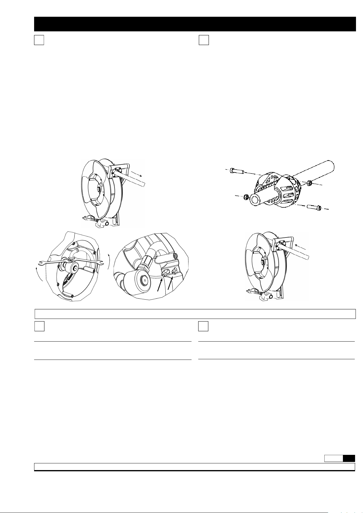
fig. 2
fig. 3 fig. 4
fig. A fig. B
fig. C fig. 5
3
R.11/09 850 819
Samson Corporation • One Samson Way • N.C. 28778 Swannanoa • Phone: 00 1 8286868511 • Fax: 00 1 8286868533
Hose installation / Instalación de la manguera
• Clamp the hose reel firmly to a work bench
• Pre tension the hose reel power spring by rotating the spool:
10m spring: 16 turns
15m spring: 19 turns
15m HD spring: 21 turns
• Introduce the hose end to fix to the hose reel through the
outlet guide and then through the opening in the drum of
the spool. Pull the hose through the drum towards the
swivel
• Fix the hose to the swivel as indicated in figure 8a and fix the
U bolt as shown in figure 8b
• Fix the hose stop to the free end of the outlet hose
• Pull out the hose slightly to free the spool latch and then
gradually release the hose to allow the hose reel to wind up the
h o s e .
• If the hose reel does not rewind satisfactorily then adjust the
tension of the power spring (see “
Spring load adjustment”
) .
• Sujetar el enrollador a una base firmemente.
• Aplicar, al enrolldor sin manguera, las vueltas de pretensión
que se indican a continuación.
resorte para 10 m: 16 vueltas
resorte para 15 m: 19 vueltas
resorte para 15 m HD: 21 vueltas
• Introducir el extremo de la manguera por la salida del
enrollador y el orificio del tambor hasta llegar a la rótula.
• Fijar la manguera a la rótula como se indica en la Figura 8a
y colocar el abarcón según la figura 8b.
• Colocar el tope de manguera en el extremo libre.
• Liberar el trinquete tirando ligeramente de la manguera y
dejar que enrolle suavemente.
• Si es necesario ajustar la tensión del resorte, seguir las
instrucciones del apartado “
Ajuste de la tensión del
r e s o r t e ” .
EEN
fig. 8a
fig. 8b
fig. 9
fig. 6
fig. 7
Hose replacement / Sustitución de la manguera
WARNING
B
EFORE REMOVING THE HOSE,CLOSE THE NEAREST SHUT OFF VALVE TO
THE REEL AND OPEN THE FLUID CONTROL GUN
TO RELEASE THE PRESSURE INSIDE THE HOSE
.
• Unwind the hose completely and then search for the ratchet
locking position (fig.6).
• Remove the hose stop (fig.7)
• Disconnect the hose as shown (fig.8a). Release the hose from
the disk by removing the clamp (fig.8b).
• Pass the new hose through the hose outlet and connect it
again to the hose reel. Assemble the clamp and assemble the
hose stop to the required length.
• Pull the hose hard enough to release the latch, and slowly
allow the hose to retract (fig.9).
ATENCIÓN
A
NTES DE RETIRAR LA MANGUERA,CERRAR LA LLAVE DE SERVICIO
MÁS CERCANA AL ENROLLADOR Y ABRIR LA PISTOLA DE SUMINISTRO
A FIN DE LIBERAR EL FLUIDO A PRESIÓN DE LA MANGUERA
.
• Desenrollar totalmente la manguera usada y buscar la
posicion de bloqueo del trinquete más proxima a esta
longitud (fig. 6).
• Aflojar entonces el tope de manguera y desmontelo (fig. 7).
• Desconectar la manguera usada según se indica en la
imagen (fig. 8a) y liberar la manguera del disco retirando el
abarcón de fijacion manguera (fig. 8b).
• Conectar la manguera nueva; para ello ntroducir el extremo de
la manguera por la salida del enrollador y el orificio del tambor
hasta llegar a la rótula y conectar de nuevo al enrollado y fijar
correctamente el abarcón. Colocar el tope manguera.
• Liberar el trinquete y acompañar lentamente la manguera al
recogerse (fig. 9).
EEN
 Loading...