

Page 1
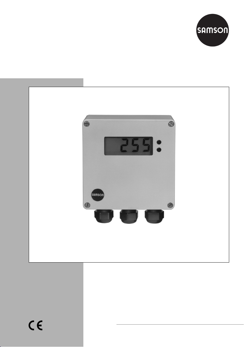
Power Supply and Indicator Unit
Type 5024-1
Fig. 1 ⋅Type 5024-1
Mounting and
Operating Instructions
EB 9539 EN
Edition October 2003
Page 2
Application
1 Application
In addition to displaying current data on the
LC display, two floating contacts indicate
The Type 5024-1 Power Supply and Indicator Unit is used to supply power to two-wire
transmitters (4 to 20 mA) such as Media 6
devices (Type 5006), Type 6051 Electrical
Transmitters for Pressure or CTMd pressure
sensors from the AB company and other devices.
when adjustable minimum and maximum
values are reached.
The direction of action of the alarm contacts
over relays that open or close when the
minimum or maximum value is reached
together with the corresponding illumination
of an LED is selectable over switches.
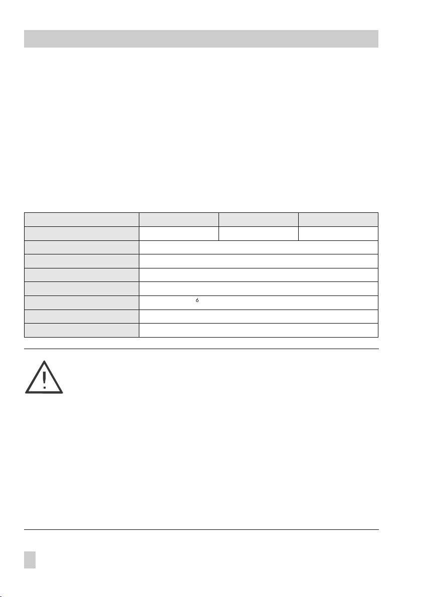
Technical data
Power Supply and Indicator Unit
Power supply 230 V, 45 to 60 Hz 115 V, 45 to 60 Hz 24 V, 45 to 60 Hz
Power consumption Approx. 1.8 VA
Measuring circuit 4 to 20 mA
Transmitter power supply 24 V at 20 mA
Output 2 floating contact alarms, max. 250 V AC/3 A
Contact rating
Perm. ambient temperature 0 to 50 °C
Degree of protection IP 54
The device may only be mounted, started up or serviced by fully trained and
qualified personnel, observing the accepted industry codes and practices.
In these mounting and operating instructions, the term experienced personnel
refers to individuals who are able to evaluate the responsibilities assigned to
them as well as recognize potential hazards due to their specialized training,
knowledge, and experience as well as their special knowledge of the relevant
standards.
Proper shipping and appropriate storage are assumed.
Type 5024-1001 5024-1002 5024-1003
$
≥
10
with AC voltage and max. 300 Ω re si sti ve lo ad
2
EB 9539
Note:
The device with a CE marking fulfills the requirements of the European Pressure Equipment Directive 97/23/EC as well as the Directive 89/336/EEC.
The declaration of conformity can be viewed and downloaded on the Internet
at http://www.samson.de.
Page 3

Installation
2Installation
Mount the device directly in the control
room or to a wall using the supplied mounting clips, nuts and bolts.
Refer to the dimensional diagram on
page 5 for the distances between holes.
2.1 Electrical connections
For electrical installation, you are required to observe the relevant electrotechnical regulations and the accident prevention regulations that
apply in the country of use.
In Germany, these are the VDE regulations and the accident prevention
regulations of the employers liability insurance.
Connect wires to terminals over the cable
glands as illustrated in Fig. 2.
2.1.1 Determining the direction of
action for the contact alarms
When connecting the relay contacts c,
and no for A1 and A2 (see Fig. 2 for switching function), the direction of action must be
set at the selector switches A1 and A2 (located at the top right-hand corner of the
lower board) as follows:
Point on switch is visible:
minimum alarm
When
is reached, the relay
is energized and the LED is illuminated.
Point on switch is not visible:
When the
maximum alarm
is reached, the
relay is energized and the LED is illuminated.
nc
_
+
Transmitter supply
LNPE
c nc no c nc no
A1 A2
Network
Fig. 2 ⋅Terminal assignment and switching function
Relay contacts
Switching function:
no
c
nc
c common connection
nc normally closed
Contact opens when the relay
is energized
no normally open
Contact closes when the relay
is energized
EB 9539
3
Page 4

Operation
3Operation
3.1 Positioning the decimal point
and selecting label with engineering units
A jumper located on the top right-hand corner of the display board can be installed at
four different positions, depending on
where the decimal point should be positioned.
Refer to Fig. 3 for the setting.
Select the required multiplication factor and
the appropriate engineering units from the
supplied adhesive label and stick them on
the front cover below the display.
Decimal point
4...20mA
Test
Δ
( )p
3.2 Setting the display
The display can be set in combination with
a rheostat of R = 10 kΩ and an ammeter
or, alternatively, a pressure transmitter or
differential pressure transmitter that has already been adjusted.
An ammeter can be connected to the TEST
terminals for the transmitters.
3.2.1 Adjusting zero
Required for this adjustment:
2-wire signal from, for example, the transmitter must be 4 mA
Turn potentiometer N on the display
board until the required initial value appears on the LC display.
I . X . X . X
Without decimal point
Direction of action
Relay
A2
A1 A2
A1
LED
mA
mA
Fig. 3 ⋅Display board
4
EB 9539
R = 10 kΩ
_
A1 A2
+
Switches and potentiometer for switching point of
max./min. alarm
NSP
Zero
Initial
Fine
Span
Page 5

Operation
3.2.2 Adjusting span:
Required for this adjustment:
2-wire signal from, for example, the transmitter must be 20 mA
First adjust the rotary switch SP (initial
adjuster), then the potentiometer SP (fine
adjuster) until the required final value appears on the LC display.
Dimensions in mm
122.5
110
3.3 Setting the contact alarms
Set the contact alarms A1 and A2 over the
selector switch and potentiometer located at
the bottom of the display board (Fig. 3).
To set the required switching point, adjust
the corresponding selector switch for A1 or
point not visible
A2 to
justed limit value then appears on the LC display.
Set the associated potentiometer until the required limit value appears on the display.
Reset the selector switch to
display value supplied by the transmitter.
. The currently ad-
point visible
to
70
90
M20x1.5
128
22
56
120.5
EB 9539
5
Page 6

SAMSON AG ⋅ MESS- UND REGELTECHNIK
Wei smül lers tra ße 3 ⋅ 60314 Frankfurt am Main ⋅ Germany
Phone: +49 69 4009-0 ⋅ Fax: +49 69 4009-1507
Internet: http://www.samson.de
EB 9539 EN
S/Z 2007-08
 Loading...