

Page 1
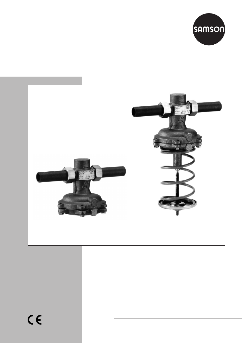
Differential Pressure Regulators
Type 45-1
Type 45-2
Type 45-3
Type 45-4
Type 45-1 Differential Pressure Regulator
Type 45-2 Differential Pressure Regulator
Mounting and
Operating Instructions
EB 3124 EN
Edition March 2008
Page 2

Contents
Contents Page
1 Design and principle of operation . . . . . . . . . . . . . . . . . . . 4
2 Installation . . . . . . . . . . . . . . . . . . . . . . . . . . . . . . 4
2.1 Mounting position . . . . . . . . . . . . . . . . . . . . . . . . . . . 4
2.2 Control line. . . . . . . . . . . . . . . . . . . . . . . . . . . . . . . 4
2.3 Strainer . . . . . . . . . . . . . . . . . . . . . . . . . . . . . . . . 4
2.4 Shut-off valves, pressure gauges. . . . . . . . . . . . . . . . . . . . . 6
3 Operation . . . . . . . . . . . . . . . . . . . . . . . . . . . . . . . 6
3.1 Start-up . . . . . . . . . . . . . . . . . . . . . . . . . . . . . . . . 6
3.2 Set point adjustment . . . . . . . . . . . . . . . . . . . . . . . . . . 6
4 Maintenance – Replacing parts . . . . . . . . . . . . . . . . . . . . . 7
4.1 Cleaning or replacing the plug . . . . . . . . . . . . . . . . . . . . . 7
4.2 Replacing the diaphragm . . . . . . . . . . . . . . . . . . . . . . . . 8
5 Troubleshooting . . . . . . . . . . . . . . . . . . . . . . . . . . . . 9
6 Nameplate . . . . . . . . . . . . . . . . . . . . . . . . . . . . . . 10
7 Dimensions and weights . . . . . . . . . . . . . . . . . . . . . . . 10
8 Customer inquiries . . . . . . . . . . . . . . . . . . . . . . . . . . 11
2 EB 3124 EN
Page 3
Safety instructions
General safety instructions
The differential pressure regulator must be installed, started up and serviced
4
only by skilled or semi-skilled staff in accordance with good engineering
practice so that employees and third persons are not exposed to danger.
All safety instructions and warnings given in these mounting and operating
instructions, particularly those concerning installation, start-up, and
maintenance, must be strictly observed.
The regulator complies with the requirements of the European Pressure
4
Equipment Directive 97/23/EC. The declaration of conformity issued for a
valve bearing the CE marking includes information on the applied
conformity assessment procedure and will be provided on request.
To ensure appropriate use, only use the regulator in applications where the
4
operating pressure and temperatures do not exceed the operating values
specified in the order.
Note that the manufacturer does not assume any responsibility for damage
caused by external forces or any other external factors.
Take appropriate safety precautions to prevent hazards that may be caused
in the regulator by the process medium, operating pressure, or moving parts.
Make sure the regulator is shipped and stored properly.
4
Note!
Depending on the field of application, allow the regulator to cool down or
4
warm up to reach ambient temperature prior to starting any work.
Always depressurize the relevant section of the plant and, if necessary, also
drain the pipeline prior to removing the regulator from the pipeline.
When controlling freezing media, protect the regulator against frost.
4
Note!
Non-electric control valves, whose valve bodies are not lined with an
insulating material coating, do not have their own potential ignition source
according to the ignition risk assessment stipulated in EN 13463-1: 2001,
section 5.2, even in the rare incident of an operating fault. Therefore, such
valve versions do not fall within the scope of Directive 94/9/EC.
EB 3124 EN 3
Page 4

Design and principle of operation
1 Design and principle of
operation
The regulators consist of a valve with a bal
anced plug and a closing actuator with an
operating diaphragm.
Types 45-1 and 45-3 have a fixed set point
determined by the set point spring inte
grated in the valve body, whereas
Types 45-2 and 45-4 allow the set point to
be adjusted by the set point springs attached
to the actuator.
The regulators are designed to maintain the
differential pressure between the high-pres
sure and low-pressure pipes at the adjusted
set point. The valve closes when the differential pressure rises.
On Types 45-1 and 45-2 installed in a flow
pipe, the medium flows through the valve in
the direction indicated by the arrow. The
high pressure in the valve outlet is transmitted through the attached control line (11) to
the high-pressure side of the operating diaphragm. The low pressure from the return
pipe is transmitted to the low-pressure side
of the diaphragm via the control line (12)
which must be routed externally on site.
On Types 45-3 and 45-4 installed in a re
turn pipe, the low pressure upstream of the
valve is directed over an internal hole (13)
to the low-pressure side of the diaphragm.
The high pressure from the flow pipe is
transmitted to the high-pressure side of the
diaphragm through the control line (11)
which must be routed externally on site.
The differential pressure acting on the oper
ating diaphragm generates a positioning
force, which positions the plug against the
force of the set point springs (8, 10).
-
-
2 Installation
2.1 Mounting position
Install the differential pressure regulator in a
horizontal pipeline with the actuator verti
cally suspended. Regulators in nominal sizes
DN 15 to 25 may also be installed in verti
cal pipelines.
For medium temperatures above 80 °C,
note that the regulator must not be installed
with the diaphragm actuator pointing up
ward.
Make sure that the medium flows through
the valve in the direction indicated by the
arrow on the valve body.
2.2 Control line
Adapt a control line with a 6 mm pipe diameter to the installation conditions on site.
Then attach it to the valve and to the pipeline according to the applicable installation
schematics (Fig. 1), making sure the control
line is free of any dirt.
2.3 Strainer
Install a strainer (e.g. SAMSON Type 1 NI)
upstream of the regulator to prevent sealing
particles, weld spatter, pipe scale, and other
impurities carried along by the process me
dium from impairing the proper operation,
especially the tight shut-off of the regulator.
Make sure that the medium flow corre
sponds with the direction indicated by the
-
arrow on the strainer body. Install the
strainer with the filter element vertically sus
pended. Ensure that ample space is avail
able to remove the filter.
-
-
-
-
-
-
-
4 EB 3124 EN
Page 5

Installation
+
Type 45-2 (45-4)
Type 45-4 only
13
12
11
Tightening
torque for
Item 3
Plug
Item 14
Screw
Legend
1 Valve body
2 Seat
3 Plug
4 Diaphragm plate
5 Nut
6 Operating diaphragm
7 Diaphragm case
8 Set point spring
9 Set point adjuster
10 Spring(s)
11 Control line, permanent (Type 45-1/-2)
Control line, external (Type 45-3/-4)
12 Control line, external (Type 45-1/-2)
13 Internal hole (Type 45-3/-4)
14 Screws
15 Spring plate
16 Bottom section of valve body
17 Support
18 Spindle
19 Manual adjuster
20 Internal excess pressure limiter
(overload protection) for Types 45-3/45-4 only
Fig. 1 · Sectional drawings
DN Nm
15...25
32...5070110
15...32
40...50818
Type 45-4 (45-2):
Set point range 0.1 to 0.5 and 0.1 to 1 bar
1
2
DN 15 to 32
Type 45-2 only
3
4
5
6
20
14
7
10
Types 45-1 and 45-2
10
9
Flow
Return flow
Flow
Return flow
–
+
–
Types 45-3 and 45-4
Type 45-1 (45-3)
Type 45-3 only
13
11
12
11
20
8
Type 45-3 only
8
4
5
6
14
15
16
17
18
19
1
2
3
4
5
6
7
14
EB 3124 EN 5
Page 6

Operation
2.4 Shut-off valves, pressure
gauges
Ideally, install hand-operated shut-off valves
both upstream of the strainer and down
stream of the differential pressure regulator.
This allows the plant to be shut down for
cleaning and maintenance routines, or when
the plant is not operated for long periods of
time.
To monitor the pressures prevailing in the
plant, install pressure gauges both upstream
and downstream of the regulator and in the
flow and return flow pipes at the pressure
tapping points.
3 Operation
3.1 Start-up
Fill the plant very slowly on start-up.
Note! When carrying out a pressure test on
the section of the plant equipped with the
pressure regulator, make sure the dia
phragm actuator cannot be damaged by the
test pressure (max. differential pressure
-
p).
Δ
On valve sizes DN 15 to 32 with set point
ranges from 0.1 to 0.5 and 0.1 to 1 bar,
the set point springs are installed in the bot
tom section of the valve body. In this case,
the set point can be directly adjusted accord
ing to the scale at the manual adjuster (19).
One turn of the set point adjuster will cause
a differential pressure change of 0.033 bar
for a pressure range of 0.1 to 1 bar and
0.02 bar for a range of 0.1 to 0.5 bar.
Note!
Do not adjust the set point to a scale value
smaller than “1”!
Under certain conditions, the set point can-
not be adjusted anymore as a result.
In this case, the following steps are recommended:
– Relieve the process pressure from both
sides of the regulator.
– Turn the adjuster counterclockwise as far
as it will go to its lowest position.
– Turn the adjuster back clockwise at least
past the scale value “1” to “2”.
– The regulator can now be readjusted.
-
-
3.2 Set point adjustment
On Types 45-2 and 45-4, adjust the re
quired differential pressure by tensioning the
spring(s) at the set point adjuster (9):
Turn the set point adjuster clockwise to
4
increase the differential pressure.
Turn the set point adjuster counterclock
4
wise to reduce the differential pressure.
6 EB 3124 EN
-
Δp
1.2
1.0
0.8
0.6
0.4
0.2
-
0
1
23
Fig. 2 · Set point adjustment according to scale value
4
0.1-1
bar
0.1-0.5
bar
6
5
Page 7

Maintenance – Replacing parts
4 Maintenance – Replacing
parts
The differential pressure regulator is mainte
nance free. Nevertheless, it is subject to nat
ural wear, particularly at the seat, plug and
operating diaphragm. Depending on the
operating conditions that prevail, inspect the
regulator at regular intervals to avoid possi
ble malfunctions.
Details on faults and the recommended ac
tion can be found in section 5. If a problem
cannot be solved with the help of the infor
mation specified in the table, contact
SAMSON.
To replace the plug and diaphragm, proceed as described in sections 4.1 and 4.2.
Caution!
Prior to carrying out any work, first
allow the relevant section of the plant
to cool down to ambient temperature
if high temperatures prevail.
Depressurize this section and drain it
depending on the medium.
We recommend that the regulator be
removed from the pipeline for carry
ing out any work on the regulator.
-
-
For Types 45-1 and 45-2, unscrew the
control line (11).
3. Remove the screws (14) and the com
-
-
plete actuator.
If applicable, remove the set point spring
(8) from the valve body.
4. For DN 15 to 25, unscrew the guide nip
-
ple of the plug assembly (3) using a socket
wrench (order no. 1280-3001).
The wrench can be made, for example
from a Gedore screwdriver bit (IN
19-19) by boring a 17 mm hole with a
17 mm diameter into the 19 mm hexa
gon bit (Fig. 3).
5. For DN 32 to 50, screw out the stopper.
Remove the plug assembly.
6. Clean the seat and plug assembly thoroughly. If the plug is damaged, replace
the entire plug assembly.
7. Check the control lines and internal bore
(of Types 45-3 and 45-4) for blockages.
To reassemble the regulator, proceed in
-
reverse order. Observe the tightening
torques specified in Fig. 1.
-
-
-
4.1 Cleaning or replacing the
plug
1. Unscrew the external control line.
Remove the regulator from the pipeline.
2. For Types 45-2 and 45-4, completely re
lease tension from the spring(s) by turn
ing the set point adjuster (9) or manual
adjuster (19) counterclockwise.
-
-
Fig. 3 · Socket wrench
17
Ø 17
SW 19
EB 3124 EN 7
Page 8

Maintenance – Replacing parts
4.2 Replacing the diaphragm
1. Unscrew the external control line. Re
move the regulator from the pipeline.
Types 45-1 and 45-2
2. For Type 45-1, unscrew the control
line (11).
3. Loosen the screws (14). Remove the
lower diaphragm case (7) including the
operating diaphragm (6) and dia
phragm plates (4) from the body.
If applicable, remove the set point
spring (8) from the valve body.
4. Unthread the nut (5). Remove the diaphragm plate. Replace the diaphragm.
To reassemble the regulator, proceed in
reverse order. Observe the tightening
torques specified in Fig. 1.
Types 45-2 and 45-4, version without
manual adjuster
2. Completely release the tension from the
spring(s) by turning the set point ad
juster (9) counterclockwise.
3. For Type 45-2, unscrew the control
line (11).
4. Loosen the screws (14). Take off the
lower diaphragm case including all ac
tuator parts as well as the diaphragm
and diaphragm plate.
5. Unthread the nut (5). Remove the dia
phragm plate. Then replace the dia
phragm.
To reassemble, proceed in reverse or
der. Observe the tightening torques
specified in Fig. 1.
-
-
-
-
-
-
Types 45-2 and 45-4, version with manual
adjuster
1. For Type 45-2, unscrew the control
line (11).
2. Completely release the tension from the
spring(s) (10) by turning the manual ad
juster (19) counterclockwise.
3. Remove the screws (14). Take off the
bottom section of the valve body (16). If
applicable, remove the set point
spring (8) from the valve body.
4. Unscrew the diaphragm assembly in
cluding the diaphragm plates, spring,
and support (17) from the spindle (18)
by turning the assembly counterclockwise. Remove it from the bottom section
of the valve body.
5. Caution! Push the spring (10) up over
the support (17) so that the spring
plate (15) is tensioned and cannot slide
off the support.
6. Fasten the bottom diaphragm plate.
Unthread the nut (5).
7. Replace the diaphragm. Tighten the
nut (5) to 22 Nm.
8. Push the complete assembly over the
-
spindle into the bottom section and
screw it onto the spindle by turning it
clockwise one turn.
9. Lift the diaphragm plate to check
whether the thread of the spring
plate (15) has engaged. If not, turn
again.
10.Hold the diaphragm stationary. Turn the
manual adjuster clockwise until the set
-
-
8 EB 3124 EN
Page 9

Troubleshooting
point spring is tensioned sufficiently to
keep the lower diaphragm plate in place
in the body and to prevent it from
moving freely.
11.If applicable, insert the set point
spring (8) into the valve body.
13. For Type 45-2, screw on the control
line.
14. Install the regulator in the pipeline.
Mount the external control line. Ad
just the differential pressure set point
as described in section 3.2.
12.Align the bottom section of the valve
body to fit the control line connections.
Thread the screws (14) evenly into the
valve body (8 Nm).
5 Troubleshooting
Fault Possible causes Recommended action
Differential
pressure
exceeds
adjusted set
point
Differential
pressure set
point not
reached
Valve too large for
Recalculate K
control task
Seat and plug untight Remove valve, clean seat and plug. If neces-
sary, replace plug (section 4.1).
Otherwise, return device for repair.
Operating diaphragm
defective
Replace diaphragm (section 4.2) or return de-
vice for repair.
Control line blocked Remove and clean control line.
Valve too small for
Check set point range and contact SAMSON.
control task
Safety device, e.g. pres
-
Check plant, unlock safety device.
sure limiter, has
been triggered
and contact SAMSON.
VS
-
Control loop
hunts
Insufficient pressure
drop across the plant
Compare existing differential pressure in the
plant with the plant’s drag.
Strainer blocked Drain and clean filter of the strainer.
Valve installed against
direction of flow
Valve too large for
Re-install valve such that direction of flow cor
responds to arrow on the body.
Recalculate KVSand contact SAMSON.
control task
-
EB 3124 EN 9
Page 10

Nameplate
6 Nameplate
1
3
2
4
2 Type designation
3 Model number
4 Date of manufacture
In the other fields:
Nominal pressure PN or ANSI Class
1 Configuration ID
or C
K
VS
V
Max. perm. temperature in °C or °F
Differential pressure set point range in bar or psi
Fig. 4 · Nameplate
Max. perm. differential pressureΔp
7 Dimensions and weights
SW SW SW
Rd
G
Types 45-2 and 45-4
L1
L
H
Rd
c
H1
ØD
G
Types 45-2 and 45-4, DN 15 to 32
0.1 to 0.5 bar and 0.1 to 1.0 bar
L1
L
H
H2
c
ØD
L1
L
dR
G
Connection nuts with welding ends
ØD
c
Types 45-2 and 45-4
H
H3
L2
L
SW
A
Connection nuts with threaded ends Connection nuts with flanges Flanged body, DN 32/40 and 50
Fig. 5 · Dimensional drawings
(Dimensions in mm)
L3 L3
L
10 EB 3124 EN
Page 11

Customer inquiries
Nominal size DN
External pipe Ø d
Connection D
Width across flats SW
Length L
Height H
Height H1
Height H2
Height H3
Diameter D
Welding ends L1
Weight 45-2/-4
App. kg 45-1/-3
Special version with threaded ends (male thread)
Length L2
Male thread A
Weight 45-2/-4
App. kg 45-1/-3
Special version with flanges PN 16/25 or version with flanged body (DN 32/40/50)
Length L3
Weight 45-2/-4
App. kg 45-1/-3
15 20 25 32 40 50
21.3 26.8 32.7 42 48 60
G ¾ G 1 G 1¼ G 1¾ G 2 G 2½
30 36 46 59 65 82
65 70 75 100 110 130
32 45 45
230 250 380
160 180 –
85 105 140
116 160
210 234 244 268 294 330
2.0 2.1 2.2 8.5 9 9.5
1.5 1.6 1.8 4.8 5.3 6.0
129 144 159 180 196 228
G ½ G ¾ G 1 G 1¼ G 1½ G 2
2.0 2.1 2.2 8.5 9 9.5
1.5 1.6 1.8 4.8 5.3 5.8
130 150 160 180 200 230
3.4 4.1 4.7 11.7 13 14.5
2.9 3.6 4.3 8 9.3 10.8
8 Customer inquiries
Should you have any inquiries, please sub
mit the following details:
Type and nominal size of the regulator
4
Threaded ends or flanges
4
Order and model numbers
4
Upstream and downstream pressures
4
Flow rate in m³/h
4
Has a strainer been installed?
4
Installation drawing
4
-
EB 3124 EN 11
Page 12

SAMSON AG · MESS- UND REGELTECHNIK
Weismüllerstraße 3 · 60314 Frankfurt am Main · Germany
Phone: +49 69 4009-0 · Fax: +49 69 4009-1507
Internet: http://www.samson.de
EB 3124 EN
S/Z 2008-03
 Loading...