

Page 1
EB 2723 EN
Translation of original instructions
Type44-7 Excess Pressure Valve
Red brass body with screwed ends
Type44-7 Excess Pressure Valve
Type44-4 and Type44-8 Safety Excess Pressure Valves (SEV)
Self-operated Pressure Regulators
Edition March 2019
Page 2
Note on these mounting and operating instructions
These mounting and operating instructions assist you in mounting and operating the device
safely. The instructions are binding for handling SAMSON devices.
Î For the safe and proper use of these instructions, read them carefully and keep them for
later reference.
Î If you have any questions about these instructions, contact SAMSON‘s After-sales Service
Department (aftersalesservice@samson.de).
The mounting and operating instructions for the devices are included in
the scope of delivery. The latest documentation is available on our website
at www.samson.de > Service & Support > Downloads > Documentation.
Denition of signal words
!
DANGER
Hazardous situations which, if not avoided,
will result in death or serious injury
!
WARNING
Hazardous situations which, if not avoided,
could result in death or serious injury
2 EB 2723 EN
!
NOTICE
Property damage message or malfunction
Note
Additional information
Tip
Recommended action
Page 3

Contents
1 Safety instructions and measures ...................................................................5
1.1 Notes on possible severe personal injury .........................................................7
1.2 Notes on possible personal injury ...................................................................8
1.3 Notes on possible property damage ................................................................9
2 Markings on the device ...............................................................................10
2.1 Regulator nameplate ....................................................................................10
2.2 Material number ..........................................................................................11
2.3 Warnings ....................................................................................................11
3 Design and principle of operation ................................................................12
3.1 Technical data .............................................................................................14
4 Measures for preparation ............................................................................18
4.1 Unpacking ..................................................................................................18
4.2 Transporting and lifting ................................................................................18
4.3 Storage .......................................................................................................18
4.4 Preparation for installation ............................................................................19
5 Mounting and start-up .................................................................................20
5.1 Mounting positions .......................................................................................20
5.2 Additional ttings .........................................................................................21
5.3 Start-up .......................................................................................................22
5.4 Gases and liquids ........................................................................................22
6 Operation ...................................................................................................22
6.1 Adjusting the set point ..................................................................................22
7 Servicing.....................................................................................................23
7.1 Cleaning and replacing the seat and plug ......................................................24
7.2 Exchanging the operating diaphragm ............................................................26
7.3 Replacing the set point springs ......................................................................28
7.4 Tightening torques and lubricant ...................................................................29
7.5 Preparation for return shipment .....................................................................30
7.6 Ordering spare parts and operating supplies .................................................30
8 Malfunctions ...............................................................................................30
EB 2723 EN 3
Page 4

Contents
9 Decommissioning and removal ....................................................................33
9.1 Decommissioning .........................................................................................33
9.2 Disposal ......................................................................................................33
10 Appendix ....................................................................................................34
10.1 After-sales service ........................................................................................34
10.2 Spare parts .................................................................................................34
10.3 Certicates ..................................................................................................37
4 EB 2723 EN
Page 5

Safety instructions and measures
1 Safety instructions and measures
Intended use
The SAMSON Type44-4, Type44-7 and Type44-8 Pressure Regulators are suitable for
pressure control of liquids and gases. The regulators are designed to operate under exactly
dened conditions (e.g. operating pressure, process medium, temperature). Therefore,
operators must ensure that the regulators are only used in operating conditions that meet the
specications used for sizing the devices at the ordering stage. In case operators intend to
use the regulators in other applications or conditions than specied, contact SAMSON.
SAMSON does not assume any liability for damage resulting from the failure to use the device for its intended purpose or for damage caused by external forces or any other external
factors.
Î Refer to the technical data and nameplate for limits and elds of application as well as
possible uses.
Reasonably foreseeable misuse
The regulators are not suitable for the following applications:
− Use outside the limits dened during sizing and by the technical data
− Use outside the limits dened by the accessories mounted on the regulator
Furthermore, the following activities do not comply with the intended use:
− Use of non-original spare parts
− Performing service and repair work not described in these instructions
− Changing parts, service or repair work on TÜV-tested Type44-4 and Type44-8
Qualications of operating personnel
The regulator must be mounted, started up, serviced and repaired by fully trained and
qualied personnel only; the accepted industry codes and practices are to be observed.
According to these mounting and operating instructions, trained personnel refers to
individuals who are able to judge the work they are assigned to and recognize possible
hazards due to their specialized training, their knowledge and experience as well as their
knowledge of the applicable standards.
EB 2723 EN 5
Page 6

Safety instructions and measures
Personal protective equipment
We recommend checking the hazards posed by the process medium being used (e.g.
uGESTIS (CLP) hazardous substance database).
Î Provide protective equipment (e.g. safety gloves, eye protection) appropriate for the pro-
cess medium used.
Î Wear hearing protection when working near the regulator.
Î Check with the plant operator for details on further protective equipment.
Revisions and other modications
Revisions, conversions or other modications of the product are not authorized by SAMSON.
They are performed at the user's own risk and may lead to safety hazards, for example.
Furthermore, the product may no longer meet the requirements for its intended use.
Warning against residual hazards
To avoid personal injury or property damage, plant operators and operating personnel must
prevent hazards that could be caused in the regulator by the process medium, the operating
pressure, the signal pressure or by moving parts by taking appropriate precautions. They
must observe all hazard statements, warning and caution notes in these mounting and operating instructions, especially for installation, start-up and service work.
We also recommend checking the hazards posed by the process medium being used (e.g.
uGESTIS (CLP) hazardous substance database).
Î Observe safety measures for handling the device as well as re prevention and explosion
protection measures.
Responsibilities of the operator
The operator is responsible for proper operation and compliance with the safety regulations.
Operators are obliged to provide these mounting and operating instructions as well as the
referenced documents to the operating personnel and to instruct them in proper operation.
Furthermore, the operator must ensure that operating personnel or third persons are not exposed to any danger.
Responsibilities of operating personnel
Operating personnel must read and understand these mounting and operating instructions as
well as the referenced documents and observe the specied hazard statements, warnings
and caution notes. Furthermore, the operating personnel must be familiar with the applicable
health, safety and accident prevention regulations and comply with them.
6 EB 2723 EN
Page 7

Safety instructions and measures
Referenced standards and regulations
The regulators comply with the requirements of the European Pressure Equipment Directive
2014/68/EU. Regulators with a CE marking have an EU declaration of conformity, which
includes information about the applied conformity assessment procedure. This EU declaration
of conformity is included in the Appendix of these instructions (see section10.3).
According to the ignition risk assessment performed in accordance with EN13463-1:2009,
section 5.2, the non-electrical regulators do not have their own potential ignition source even
in the rare incident of an operating fault. As a result, they do not fall within the scope of Directive 2014/34/EU.
Î For connection to the equipotential bonding system, observe the requirements specied in
section 6.4 of EN60079-14 (VDE0165 Part 1).
1.1 Notes on possible severe personal injury
!
DANGER
Risk of bursting in pressure equipment.
Regulators and pipelines are pressure equipment. Improper opening can lead to regulator components bursting.
Î Observe the maximum permissible pressure for regulator and plant.
Î If necessary, a suitable overpressure protection must be installed on site in the plant
section.
Î Before starting any work on the regulator, depressurize all plant sections
concerned.
Î Drain the process medium from all the plant sections concerned as well as the reg-
ulator.
Î Wear personal protective equipment.
EB 2723 EN 7
Page 8

Safety instructions and measures
1.2 Notes on possible personal injury
!
WARNING
Risk of personal injury due to preloaded springs.
Regulators in combination with preloaded set point springs are under tension. These
regulators can be identied by the red warning label on the actuator's set point springs.
Î Before starting any work on the set point springs, relieve the compression from the
preloaded springs.
Î Only use the SAMSON disassembly tool (1280-4052).
Crush hazard arising from moving parts.
The regulator contains moving parts (actuator and plug stems), which can injure hands
or ngers if inserted into the valve.
Î Do not insert hands or ngers between the set point springs while the regulator is in
operation.
Î Before performing any work on the regulator, depressurize the plant. Disconnect or
shut off the external control line.
Risk of personal injury due to residual process medium in the regulator.
While working on the regulator, residual process medium can escape and, depending
on its properties, may lead to personal injury, e.g. (chemical) burns.
Î If possible, drain the process medium from all the plant sections concerned and the
regulator.
Î Wear protective clothing, safety gloves and eyewear.
Risk of burn injuries due to hot or cold components and pipelines.
Depending on the process medium, regulator components and pipelines may get very
hot or cold and cause burn injuries.
Î Allow components and pipelines to cool down or heat up.
Î Wear protective clothing and safety gloves.
Damage to health relating to the REACH regulation.
If a SAMSON device contains a substance which is listed as being a substance of very
high concern on the candidate list of the REACH regulation, this circumstance is indicated on the SAMSON delivery note.
Î Information on safe use of the part affected uwww.samson.de/reach-en.html
8 EB 2723 EN
Page 9
Safety instructions and measures
1.3 Notes on possible property damage
!
NOTICE
Risk of regulator damage due to contamination (e.g. solid particles) in the pipeline.
The plant operator is responsible for cleaning the pipelines in the plant.
Î Flush the pipelines before start-up.
Risk of regulator damage due to unsuitable medium properties.
The regulator is designed for a process medium with dened properties.
Î Only use the process medium specied for sizing.
Risk of regulator damage due to the use of unsuitable lubricants.
The lubricants to be used depend on the regulator material. Unsuitable lubricants may
corrode and damage the surface.
Î Only use lubricants approved by SAMSON.
Risk of leakage and regulator damage due to excessively high or low tightening
torques.
Observe the specied torques on tightening regulator components. Excessively tightened
torques lead to parts wearing out quicker. Parts that are too loose may cause leakage.
Î Observe the specied tightening torques.
Risk of regulator damage due to the use of unsuitable tools.
Certain tools are required to work on the regulator.
Î Only use tools approved by SAMSON.
Note
SAMSON's After-sales Service department can support you concerning lubricant, tightening torques and tools approved by SAMSON.
EB 2723 EN 9
Page 10
Markings on the device
2 Markings on the device
2.1 Regulator nameplate
1 2 3
4 5
6 10 7
8 9
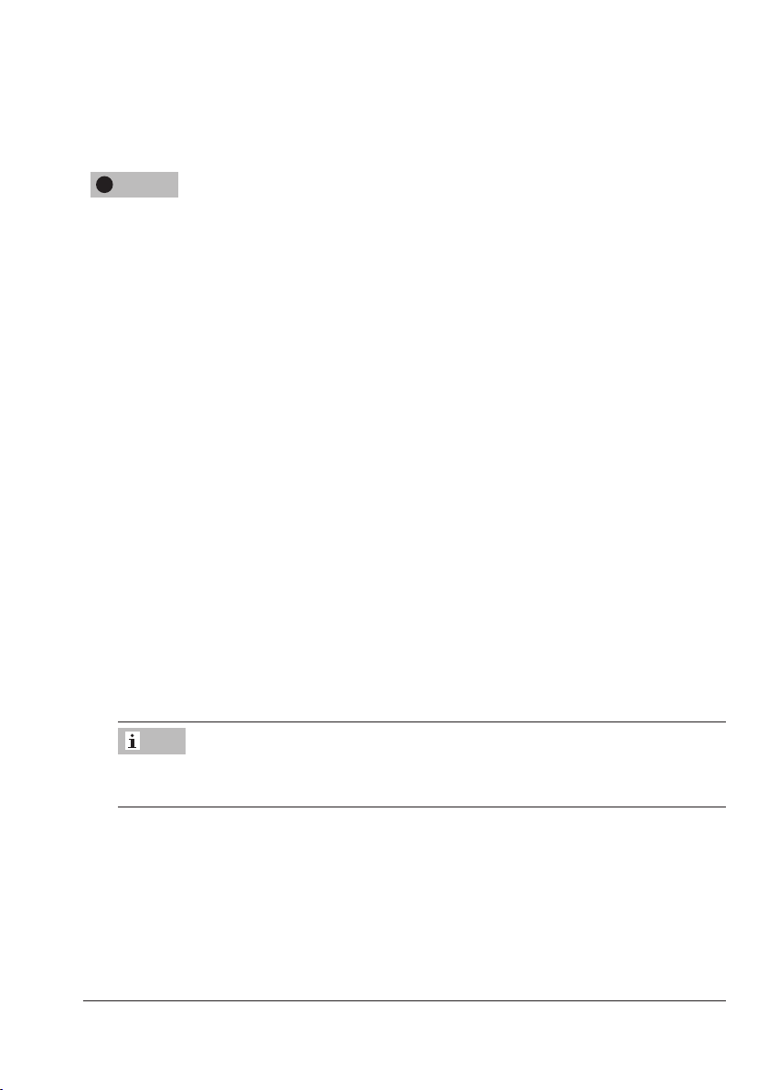
Fig.1: Nameplate
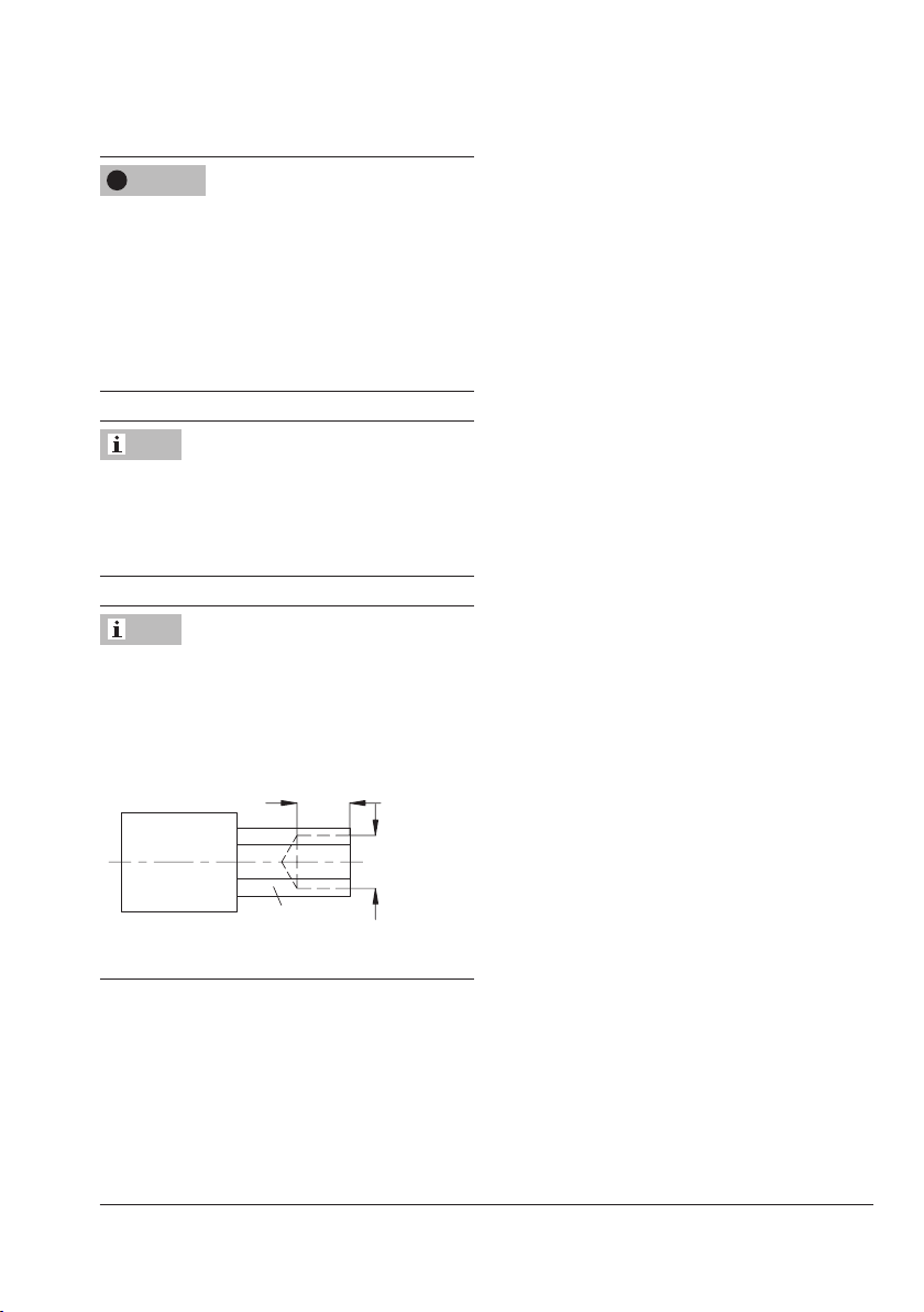
The nameplate of all sizes is afxed to the
body (see Fig.2).
1 Model number
2 Conguration ID (Var.-ID) and device index
3 Order number or year of manufacture
4 Type designation
5 Pressure rating PN
coefcient
6 K
VS
7 Perm. temperature in °C
8 Set point range in bar
9 Max. perm. differential pressure Δp in bar
10 Arrow indicating the direction of ow
Nameplate
position on
the body
Fig.2: Nameplate on the bodies
10 EB 2723 EN
Page 11

Markings on the device
2.2 Material number
Specifying the conguration ID, you can contact us to nd out which material is used. The
conguration ID is specied on the nameplate (2 (conguration ID and device index).
For more details on the nameplate, see section2.1.
2.3 Warnings
The red adhesive labels indicate hazards
that may arise while working on the regulator. Risk of personal injury.
Î Observe the warnings.
EB 2723 EN 11
Page 12

Design and principle of operation
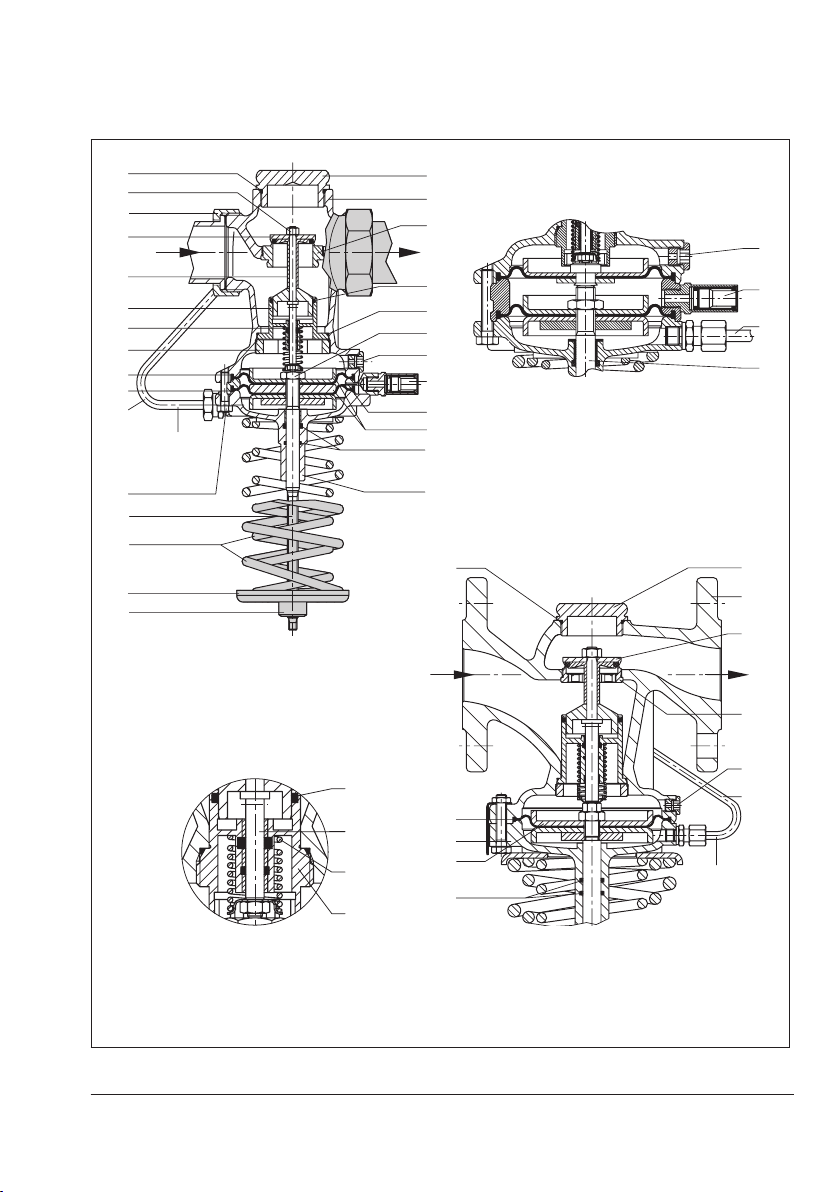
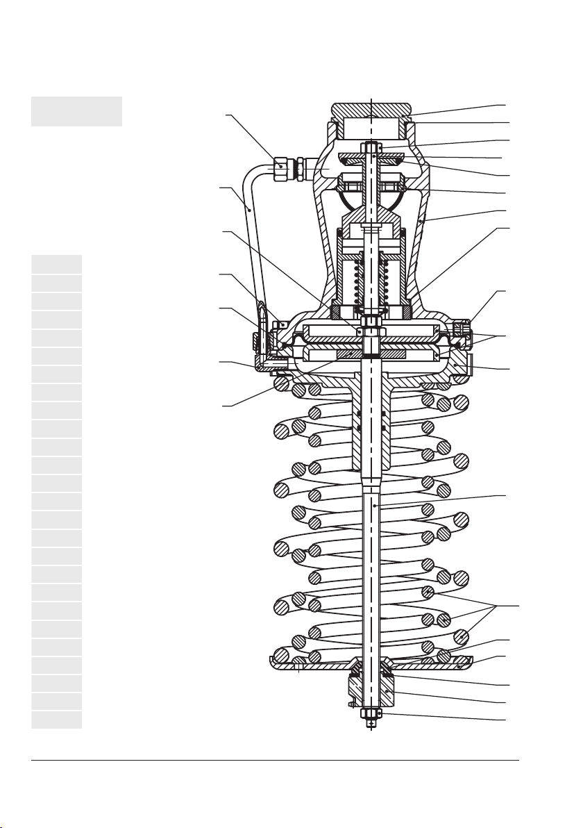
3 Design and principle of oper-
ation
Î Refer to Fig.3
The regulator are closed when relieved of
pressure. They open when the upstream
pressure rises above the adjusted set point.
The Type44-4, Type44-7 and Type44-8
Excess Pressure Valves mainly consist of the
valve (1) with seat (2) and plug (3) as well
as the actuator with operating diaphragm
(6.1), set point spring (8) and set point adjuster (10).
The excess pressure valve is used to maintain
the pressure upstream of the regulator to an
adjusted set point.
The process medium ows through the regulator between seat and plug in the direction
indicated by the arrow on the body. The position of the valve plug determines the ow
rate and, as a result, the upstream pressure.
The upstream pressure p
transmitted over the control line (11) to the
operating diaphragm (6.1) where it is converted into a positioning force. This force is
used to move the valve plug according to the
force of the set point spring (8). The spring
force can be adjusted at the set point adjuster (10).
The Type44-8 Safety Excess Pressure Valve
additionally has a second backup diaphragm (6.2). Upon failure of the rst operating diaphragm (6.1) the regulator contin-
ues to function using the backup diaphragm (6.2). In this case, the regulator
functions as a safety valve when the upstream pressure rises too far and opens the
to be controlled is
1
valve. Diaphragm failure is indicated by a
red mark in the diaphragm rupture indicator
(12) (point of response at approx. 1.5bar)
or medium escapes at the test connection.
The Type44-4 Safety Excess Pressure Valve
additionally has a second backup diaphragm (6.2). Upon failure of the rst operating diaphragm (6.1) the regulator is fully
opened. Diaphragm failure is indicated by a
red mark in the diaphragm rupture indicator
(12) (point of response at approx. 1.5bar)
or medium escapes at the test connection.
1 Valve body
1.1 Stopper
1.2 Seal
1.3 Seal
2 Seat
3 Plug with plug seal
3.1 Balancing piston
3.2 Plug nut
3.3 Plug stem
3.4 Plug spring
3.5 Plug nipple
3.6 Guide nipple
4 Coupling nut
5 Inspection bore
6 Actuator housing
6.1 Operating diaphragm
6.2 Backup diaphragm
7 Diaphragm stem
8 Set point spring(s)
9 Spring plate
10 Set point adjuster
11 Control line
12 Diaphragm rupture indicator
13 Body screws
14 Distance ring
15 Diaphragm plate nut
16 Diaphragm plate
17 O-rings
12 EB 2723 EN
Page 13
Design and principle of operation
1.1
3.3
3.4
3.5
3.2
6.2
6.1
3.1
1.2
1.3
3.6
11
12
7
2
p
1.1
6.1
1.2
3.1
3.4
3.6
3.3
4
3
p
1
11
+
Turned into the
plane of
projection
13
7
8
9
10
Type44-8 SEV (DN32 to 50),
DN15 to 25, plug section
body with screwed ends
1
2
p
2
5
15
5
12
14
Type44-4 SEV
16
17
6
1
3
p
2
5
11
+
16
17
1
6
Turned into the
plane of
projection
Type44-8 (DN32 to 50),
anged valve body
Fig.3: Functional diagram of Type44-7 Excess Pressure Valve as well as Types44-4 and 44-8
Safety Excess Pressure Valves (SEV)
EB 2723 EN 13
Page 14

Design and principle of operation
3.1 Technical data
The regulator's nameplate contains information on the regulator version (see section2.1).
Process medium and scope of application
The excess pressure valve and safety excess
pressure valve are designed to maintain the
pressure upstream of the regulator to the adjusted set point especially in district heating
systems and extended heating systems.
Type44-4, Type44-7 and Type44-8 are
suitable for controlling liquids and gases.
− Max. permissible temperatures for gases
up to 80°C
− Air/nitrogen up to 150°C
− Liquids up to 150°C
The regulator is closed when relieved of
pressure. It opens when the upstream pressure rises above the adjusted set point.
Type test
The Type44-4 and Type44-8 Regulators
have been typetested as safety excess pressure valves (SEV) by the German Technical
Inspectorate (TÜV).
The test mark is available on request.
1)
Temperature range
The Type44-4, Type44-7 and Type44-8
Regulators are designed for a temperature
range from 0 to +150°C.
Leakage class
All regulators have the leakage class I
according to IEC60534-4.
Noise emission
SAMSON is unable to make general statements about noise emission as it depends on
the regulator version, plant facilities, process
medium and operating conditions.
!
WARNING
Risk of hearing loss or deafness due to loud
noise.
Wear hearing protection when working near
the regulator.
Dimensions and weights
Table4 provides a summary of the dimensions and weights of the Type44-4, Type447 and Type44-8 Regulators. The lengths and
heights in the dimensional drawings are
shown on page17 onwards.
1)
With seals made of FKM
14 EB 2723 EN
Page 15

Design and principle of operation
Table1: Technical data · All pressures in bar (gauge)
Regulator Excess pressure valve
44-7 44-4 (SEV)·44-8 (SEV)
Red brass body Male thread DN15, 20, 25, 32, 40 and 50
Connection
Pressure rating PN 25
Max. permissible
temperature
Max. permissible differential pressure ∆p 11bar
Set point range (continuously
adjustable)
Leakage class according to IEC60534-4 ≤0.05% of K
Compliance
Max. perm. ambient temperature 60°C
1)
With seals made of FKM; without type test (Types44-4 and 44-8)
2)
Special version, without type test
Spheroidal graphite iron
body
Flanges DN32, 40 and 50
Liquids 150°C
Non-ammable gases 80°C
Air and nitrogen
1)
150°C
Type44-7 1 to 4bar·2 to 4.4bar·2.4 to 6.6bar·6 to 11bar
Type44-4 (SEV)
Type44-8 (SEV)
1 to 4bar
2)
·2 to 4.4bar·2.4 to 6.6bar·6 to 11bar
coefcient
VS
·
Table2: Materials · Material numbers according to DIN EN
Body Red brass CC499K
Seat 1.4305
Plug Brass 2.0402 and stainless steel 1.4305 with EPDM soft seal
Actuator housing/
intermediate ring
Red brass CC499K
Set point spring 1.4310
Operating diaphragm EPDM with fabric reinforcement
Seals EPDM
1)
Special version, e.g. for mineral oils: FKM
Spheroidal graphite iron
EN-GJS-400-18-LT
1)
1)
1)
EB 2723 EN 15
Page 16

Design and principle of operation
Table3: KVS coefcients
Body with screwed ends
Valve size DN 15 20 25 32 40 50
coefcients
K
VS
values 0.60 0.55 0.5 0.45
x
Fz
Standard version 4.0 6.3 8.0 12.5 16.0 20.0
Special version 1.0·2.5 —
Flanged body
Valve size DN DN32 DN40 DN50
coefcients 12.5 20.0 25.0
K
VS
values 0.55 0.5 0.45
x
Fz
Table4: Dimensions · Weights
Valve size DN 15 20 25 32 40 50
Length L mm 65 70 75 100 110 130
Pipe Ø d mm 21.3 26.9 33.7 42.4 48.3 60.3
Connection R G¾ G1 G1¼ G1¾ G2 G2½
Width across ats SW mm 30 36 46 59 65 82
Type44-7 mm 230 250 390
Height H
Type44-4 mm 235
1)
Type44-8 mm 235 250 395
Height H1 mm 41 58
Actuator housing ØD mm 116 160
393
Version with welding ends
Length L1 mm 210 234 244 268 294 330
Weight kg (approx.) 2.0 2.1 2.2 8.5 9.0 9.5
Version with threaded ends
Length L2 mm 129 144 159 192 206 228
Male thread A G½ G¾ G1 G1¼ G1½ G2
Weight kg (approx.) 2.0 2.1 2.2 8.5 9.0 9.5
Version with screwed-on anges or with anged body (DN32 to 50 only)
Length L3 mm – 180 200 230
Weight kg (approx.) – 11.7 13.0 14.5
1)
273mm with 6 to 11bar set point range
16 EB 2723 EN
Page 17

Dimensional drawings
L 1
ØD
H1
ØD
L 1
R
H1
L3
L 2
H1
Type44-7·Body: CC499K Type44-4·Type44-8·Body: CC499K
Design and principle of operation
Version with welding ends
SW
L
RØd
Version with anged valve body
Type44-4, Type44-7 and Type44-8
Body: spheroidal graphite iron
SW
L
Ød
~36
H
1)
Version with threaded ends
H
SW
RA
Fig.4: Dimensions
1)
DN32, 40 and 50
EB 2723 EN 17
Page 18

Measures for preparation
4 Measures for preparation
After receiving the shipment, proceed as follows:
1. Check the scope of delivery. Compare
the shipment received with the delivery
note.
2. Check the shipment for transportation
damage. Report any damage to
SAMSON and the forwarding agent
(refer to delivery note).
4.1 Unpacking
Note
Do not remove the packaging until immediately before installing the valve into the pipeline.
4.2 Transporting and lifting
Due to the low service weight, lifting equipment is not required to lift and transport the
regulator (e.g. to install it into the pipeline).
Transport instructions
− Protect the device against external inu-
ences (e.g. impact).
− Do not damage the corrosion protection
(paint, surface coatings). Repair any
damage immediately.
− Protect the device against moisture and
dirt.
− Observe the permissible ambient tem-
peratures (see section3.1).
4.3 Storage
!
NOTICE
Risk of regulator damage due to improper
storage.
− Observe storage instructions.
− Avoid long storage times.
− Contact SAMSON in case of different stor-
age conditions or long storage periods.
Note
We recommend regularly checking the device and the prevailing storage conditions
during long storage periods.
Storage instructions
− Protect the device against external inu-
ences (e.g. impact).
− Do not damage the corrosion protection
(paint, surface coatings). Repair any
damage immediately.
− Protect the device against moisture and
dirt. Store it at a relative humidity of less
than 75%. In damp spaces, prevent condensation. If necessary, use a drying
agent or heating.
− Make sure that the ambient air is free of
acids or other corrosive media.
− Observe the permissible ambient tem-
peratures (see section3.1).
− Do not place any objects on the device.
18 EB 2723 EN
Page 19
Measures for preparation
Special storage instructions for elastomers
Elastomer, e.g. operating diaphragm
− To keep elastomers in shape and to pre-
vent cracking, do not bend them or hang
them up.
− We recommend a storage temperature of
15°C for elastomers.
− Store elastomers away from lubricants,
chemicals, solutions and fuels.
Tip
SAMSON's After-sales Service department
can provide more detailed storage instructions on request.
4.4 Preparation for installation
Proceed as follows:
Î Flush the pipelines.
Note
The plant operator is responsible for cleaning the pipelines in the plant.
Î Check the regulator to make sure it is
clean.
Î Check the regulator for damage.
Î Check to make sure that the type desig-
nation, valve size, material, pressure rat-
ing and temperature range of the regula-
tor match the plant conditions (size and
pressure rating of the pipeline, medium
temperature etc.).
Î Check any mounted pressure gauges to
make sure they function.
EB 2723 EN 19
Page 20

Mounting and start-up
1234 51
p
2
5 Mounting and start-up
!
!
NOTICE
NOTICE
Risk of overheating due to excessive ambient
temperatures or insufcient heat dissipation
when components are insulated.
− Do not include the regulator in the insula-
tion of the pipeline.
!
NOTICE
Risk of impaired functioning of the regulator
and leakage at the joint due to installation
under tension.
− Bolt the regulator to the pipeline free of
stress.
− If necessary, support the pipelines near to
the connections.
− Do not attach supports directly to the regu-
lator.
5.1 Mounting positions
Install Type44-4, Type44-7 and Type44-8
with the actuator housing suspended downward in horizontal pipelines.
Installation conditions
Î Make sure that the regulator remains
freely accessible after the plant has been
completed.
Î Install a strainer upstream of the regula-
tor (Type44-7 only). See section5.2.
Î Make sure the direction of ow matches
the direction indicated by the arrow on
the body.
Î Install the regulator free of stress.
Î The valves are connected to the pipeline
using threaded ends, welding ends or
anged body.
1
1 Shut-off valve
2 Upstream pressure gauge
3 Strainer (Type44-7 only)
4 Excess pressure valve
5 Downstream pressure gauge
Type44-7 Excess Pressure Valve
Fig.5: Pressure control with Type44-7 (installation example)
20 EB 2723 EN
p
Page 21
Mounting and start-up
!
NOTICE
Possible malfunction and damage due to adverse weather conditions (temperature, humidity).
− Do not install the device outdoors or in
rooms prone to frost.
− Protect the regulator against frost if it is
used to control freezing media.
− Either heat the regulator or remove it from
the plant and completely drain the residual
medium after a plant shutdown.
5.2 Additional ttings
Strainer
!
NOTICE
Do not install a strainer upstream of
Type44-4 and Type44-8 Safety Excess Pressure Valves.
A strainer installed upstream in the ow pipe
holds back any dirt or other foreign particles
carried along by the medium. For example,
the SAMSON Type1NI Strainer is suitable
(uT1010).
The following points must be observed
during installation of the strainer:
− Install the strainer upstream of the
Type44-7 Regulator.
− Allow sufcient space to remove the lter.
− Observe the ow direction.
− In horizontal pipelines with gases or liq-
uids, the lter element faces downward.
The lter element faces sideways in applications with steam.
− Install strainers in vertical pipelines with
the medium owing upward with the
drain plug facing upward.
Note
Check the strainer at regular intervals and
clean it, if necessary.
Shut-off valve
Install a hand-operated shut-off valve both
upstream of the strainer and downstream of
the regulator (see Fig.5). This allows the
plant to be shut down for cleaning and
maintenance, and when the plant is not used
for longer periods of time.
Pressure gauges
Install a pressure gauge both upstream and
downstream of the regulator to monitor the
pressures prevailing in the plant (see Fig.5).
EB 2723 EN 21
Page 22

Operation
5.3 Start-up
!
DANGER
Risk of personal injury due to process medium escaping under pressure.
− First start up the regulator after mounting
all parts.
!
NOTICE
Risk of the operating diaphragm bursting
due to excessive pressure during pressure
testing.
− The pressure must not exceed the maxi-
mum permissible pressure by 1.5 times the
pressure rating.
− Remove the control line from the regulator
and seal the open connection with a blanking plug (accessories: blanking plug 83230030 and seal 8412-0771).
Once installed in the pipeline, the regulator
can be put into operation.
5.4 Gases and liquids
Î Open the shut-off valves slowly prefera-
bly starting from the downstream side.
Î Avoid pressure surges.
Î Make sure that the air contained in the
plant (when liquids are used) escapes as
quickly as possible.
6 Operation
6.1 Adjusting the set point
Î Refer to Fig.3
Adjust the required set point by turning the
set point adjuster (10) with an open-end
wrench.
Note
The following open-end wrench sizes are required to adjust the set point:
− 19mm for DN15 to 32
− 27mm for DN40 and 50
Set point adjuster
Î Undo the lock nut (for 6 to 11bar set
point range only).
Î Turn the set point screw clockwise () to
increase the pressure set point.
Î Turn the set point screw counterclockwise
() to reduce the pressure set point.
Î Tighten the lock nut (for 6 to 11bar set
point range only).
The pressure gauge (Fig.5) installed on the
downstream side on site allows the adjusted
set point to be monitored.
The set point range can be changed by exchanging the set point spring (8) (see section7.3).
22 EB 2723 EN
Page 23
Servicing
7 Servicing
The regulator does not require any maintenance. Nevertheless, it is subject to natural
wear, particularly at the seat, plug and operating diaphragm. Depending on the operating conditions, check the regulator at regular
intervals to avoid possible malfunctions. Operators are responsible for drawing up an
inspection and test plan.
Details on faults and how to remedy them
can be found in Table5.
We recommend removing the regulator from
the pipeline before performing any maintenance or service work.
!
DANGER
Risk of bursting in pressure equipment.
Regulators and pipelines are pressure equipment. Improper opening can lead to bursting
of the regulator.
− Before starting any work on the regulator,
depressurize all plant sections concerned
as well as the regulator.
− Drain the process medium from all the
plant sections concerned as well as the
regulator.
− Wear personal protective equipment.
!
WARNING
Risk of personal injury due to residual process medium in the regulator.
While working on the regulator, residual
process medium can escape and, depending
on its properties, may lead to personal in-
jury, e.g. (chemical) burns.
Wear protective clothing, safety gloves and
eyewear.
!
WARNING
Risk of burn injuries due to hot or cold components and pipeline.
Regulator components and the pipeline may
become very hot or cold. Risk of burn injuries.
− Allow components and pipelines to cool
down or heat up.
− Wear protective clothing and safety gloves.
!
NOTICE
Risk of regulator damage due to incorrect
servicing or repair.
Service and repair work must be performed
by trained staff only.
!
NOTICE
Risk of regulator damage due to excessively
high or low tightening torques.
Observe the specied torques on tightening
regulator components. Excessively tightened
torques lead to parts wearing out quicker.
Parts that are too loose may cause leakage.
Observe the specied tightening torques.
!
NOTICE
Risk of regulator damage due to the use of
unsuitable tools.
Only use tools approved by SAMSON.
EB 2723 EN 23
Page 24

Servicing
!
NOTICE
Risk of regulator damage due to the use of
unsuitable lubricants.
Only use lubricants approved by SAMSON.
Note
SAMSON's After-sales Service department
can support you concerning lubricant,
tightening torques and tools approved by
SAMSON.
Note
The regulator was checked by SAMSON
before it left the factory.
− Certain test results (seat leakage and leak
test) certied by SAMSON lose their validity when the regulator is opened.
− The product warranty becomes void if
service or repair work not described in
these instructions is performed without
prior agreement by SAMSON's After-sales
Service department.
− Only use original spare parts by
SAMSON, which comply with the original
specications.
Tip
SAMSON's After-sales Service department
can support you in drawing up an inspection
and test plan for your plant.
7.1 Cleaning and replacing the seat and plug
!
DANGER
Risk of personal injury due to preloaded
springs.
Regulators in combination with preloaded
set point springs are under tension. These
regulators can be identied by the red warning label on the actuator's set point springs.
− Before starting any work on the springs,
relieve the compression from the preloaded
springs.
− Only use the SAMSON disassembly tool
(1280-4052).
!
NOTICE
Risk of regulator damage due to excessively
high or low tightening torques.
Observe the specied torques on tightening
regulator components. Excessively tightened
torques lead to parts wearing out quicker.
Parts that are too loose may cause leakage.
Observe the specied tightening torques.
!
NOTICE
Risk of damage to the facing of the seat and
plug due to incorrect service or repair.
Always replace both the seat and plug.
24 EB 2723 EN
Page 25
Servicing
17
Ø 17
SW 19
!
NOTICE
Risk of TÜV approval (based on AGFW
worksheet FW506) for Types44-4 and
44-8 becoming void.
Consult SAMSON's After-sales Service department before you change parts or per-
form service or repair work on TÜV-tested
Type44-4 and Type44-8 Regulators.
Note
SAMSON's After-sales Service department
can support you concerning lubricant,
tightening torques and tools approved by
SAMSON.
Note
The socket wrench for DN15 to 25 can also
be made, for example from a GEDORE
screwdriver bit (IN19-19) by drilling a
17-mm-deep hole (Ø17) into a 17mm
hexagon bit.
SAMSON order no. 1280-3001
Î Refer to Fig.3
Disassembly of Type44-7
1. Put the regulator out of operation (see
section9.1).
2. Completely relieve the tension from the
set point spring (8) by turning the set
point adjuster (10) counterclockwise ().
3. Remove the device from the pipeline
4. Unscrew the control line (11).
5. Unscrew the body stopper (1.1).
6. Remove the seal (1.2).
7. Unscrew the body screws (13) and take
off the actuator housing (6) together with
the set point spring (8).
8. Unscrew the plug nut (3.2) and take the
plug (3) off the plug stem.
9. DN15 to 25: unscrew and pull out the
guide nipple (3.6) using a socket
wrench.
DN32 to 50: unscrew the plug nipple
(3.5) and pull out the guide nipple (3.6).
10. Remove the seal (1.3).
11. Thoroughly clean the seat (2), plug (3)
and balancing piston (3.1). Replace
damaged parts with new ones.
12. Check the control line (11) for any blockages.
13. Unscrew the seat (2) using a seat wrench
if the seat facing is damaged.
EB 2723 EN 25
Page 26

Servicing
Assembly of Type44-7
1. Screw in the seat using a seat wrench.
Observe the tightening torques specied
in section7.4.
2. Renew the seal (1.3) and insert it into the
body.
3. DN15 to 25: insert and screw in the
guide nipple (3.6). Observe the tightening torques specied in section7.4.
DN32 to 50: insert the the guide nipple
(3.6) and screw in the plug nipple (3.5).
Observe the tightening torques specied
in section7.4.
4. Place the plug (3) onto the plug stem and
screw on the plug nut (3.2). Observe the
tightening torques specied in section7.4.
5. Renew the seal (1.2) and insert it into the
body.
6. Screw in the body stopper (1.1). Observe the tightening torques specied in
section7.4.
7. Check the facings of the actuator housing (6) for dirt and clean them, if necessary.
8. Place the actuator housing (6) on the
valve body (1) and screw tight the body
screws (13). Observe the tightening
torques specied in section7.4.
9. Screw on the control line (11). Observe
the tightening torques specied in section7.4.
10. Put the regulator into operation (see section5.3).
7.2 Exchanging the operating diaphragm
!
DANGER
Risk of personal injury due to preloaded
springs.
Regulators in combination with preloaded
set point springs are under tension. These
regulators can be identied by the red warning label on the actuator's set point springs.
− Before starting any work on the springs,
relieve the compression from the preloaded
springs.
− Only use the SAMSON disassembly tool
(1280-4052).
!
NOTICE
Risk of regulator damage due to excessively
high or low tightening torques.
Observe the specied torques on tightening
regulator components. Excessively tightened
torques lead to parts wearing out quicker.
Parts that are too loose may cause leakage.
Observe the specied tightening torques.
!
NOTICE
Risk of TÜV approval (based on AGFW
worksheet FW506) for Types44-4 and
44-8 becoming void.
Consult SAMSON's After-sales Service
department before you change parts or
perform service or repair work on TÜVtested Type44-4 and Type44-8 Regulators.
26 EB 2723 EN
Page 27

Servicing
Note
SAMSON's After-sales Service department
can support you concerning lubricant,
tightening torques and tools approved by
SAMSON.
Note
The stem surface is roller-burnished. Do not
reface the stem.
After replacing the diaphragm stem, the
nipple (guide bushing) in the actuator case
must be replaced as well.
Tip
The associated order number is written on
the actual rolling diaphragm.
Î Refer to Fig.3
Disassembly of Type44-7
1. Put the regulator out of operation (see
section9.1).
2. Completely relieve the tension from the
set point spring (8) by turning the set
point adjuster (10) counterclockwise ().
3. Remove the device from the pipeline
4. Unscrew the control line (11).
5. Use the SAMSON disassembly tool to
unscrew the set point adjuster (10) from
the diaphragm stem (7).
6. Lift off the spring plate (9) and the set
point spring (8).
7. Unscrew the body screws (13) and take
off the actuator housing (6).
8. Unscrew the diaphragm plate nut (15)
from the diaphragm stem (7).
9. Take off the diaphragm plate (16) and
operating diaphragm (6.1).
10. Examine the diaphragm stem (7) for
score marks. Replace, if necessary.
Assembly of Type44-7
1. Place the operating diaphragm (6.1) together with the diaphragm plate (16) onto the diaphragm stem (7) and tighten
the nut (15). Observe the tightening
torques specied in section7.4.
2. Apply lubricant to the diaphragm stem
(7). See section7.4.
3. Insert the diaphragm stem (7) together
with the operating diaphragm (6.1) into
the actuator housing (6).
4. Check the facings of the actuator housing (6) for dirt and clean them, if necessary.
5. Place the actuator housing (6) on the
valve body (1) and tighten the screws
(13) evenly. Observe tightening torque
specied in section7.4.
6. Use the SAMSON disassembly tool to
screw the valve body (1) together with
spring plate (9) and the set point springs
(8).
7. Screw the set point adjuster (10) onto the
diaphragm stem (7).
8. Screw on the control line (11). Observe
tightening torque specied in section7.4.
9. Put the regulator into operation (see section5.3).
EB 2723 EN 27
Page 28
Servicing
7.3 Replacing the set point springs
!
DANGER
Risk of personal injury due to preloaded
springs.
Regulators in combination with preloaded
set point springs are under tension. These
regulators can be identied by the red warning label on the actuator's set point springs.
− Before starting any work on the springs,
relieve the compression from the preloaded
springs.
− Only use the SAMSON disassembly tool
(1280-4052).
!
NOTICE
Risk of regulator damage due to excessively
high or low tightening torques.
Observe the specied torques on tightening
regulator components. Excessively tightened
torques lead to parts wearing out quicker.
Parts that are too loose may cause leakage.
Observe the specied tightening torques.
!
NOTICE
Risk of TÜV approval (based on AGFW
worksheet FW506) for Types44-4 and
44-8 becoming void.
Consult SAMSON's After-sales Service department before you change parts or per-
form service or repair work on TÜV-tested
Type44-4 and Type44-8 Regulators.
Note
SAMSON's After-sales Service department
can support you concerning lubricant, tightening torques and tools approved by SAMSON.
Refer to Fig.3
Disassembly of Type44-7
1. Put the regulator out of operation (see
section9.1).
2. Completely relieve the tension from the
set point spring (8) by turning the set
point adjuster (10) counterclockwise ().
3. Remove the device from the pipeline
4. Unscrew the control line (11).
5. Use the SAMSON disassembly tool to
unscrew the set point adjuster (10) from
the diaphragm stem (7).
6. Lift off the spring plate (9) and the set
point spring (8).
7. Examine the diaphragm stem (7) for
score marks. Replace, if necessary. Proceed as described in section7.2.
Assembly of Type44-7
1. Use the SAMSON disassembly tool to
screw the valve body (1) together with
spring plate (9) and the set point springs
(8).
2. Screw the set point adjuster (10) onto the
diaphragm stem (7).
3. Screw on the control line (11). Observe
tightening torque specied in section7.4.
4. Put the regulator into operation (see section5.3).
28 EB 2723 EN
Page 29

Note
Change the nameplate and conguration ID
after changing the set point range.
7.4 Tightening torques and lubricant
Î Refer to Fig.3
Component Valve size Tightening torque inNm
Stopper (1.1)
Seat (2)
Plug nut (3.2)
Plug nipple (3.5) DN32 to 50 110
Guide nipple (3.6) DN15 to 25 70
Coupling nut (4)
Control line connection (11) DN15 to 50 22
Body screws (13)
Diaphragm plate nut (15)
DN15 to 25 70
DN32 to 50 110
DN15 to 25 45
DN32 to 50 110
DN15 to 25 4
DN32 to 50 8
DN15 200
DN20 250
DN25 300
DN32 400
DN40 600
DN50 800
DN15 to 32 8
DN40 to 50 18
DN15 to 25 40
DN32 to 50 80
Servicing
Lubricants Item no.
Gleitmo 591 8150-0111
EB 2723 EN 29
Page 30
Malfunctions
7.5 Preparation for return shipment
Defective devices can be returned to
SAMSON for repair. Proceed as follows to
return devices to SAMSON:
1. Put the regulator out of operation (see
section9.1).
2. Decontaminate the regulator. Remove
any residual process medium.
3. Fill in the Declaration on Contamination.
The declaration form can be downloaded from our website at
uwww.samson.de > Service & Support
> After-sales Service.
4. Send the device together with the lled-in
form to your nearest SAMSON subsidiary. SAMSON subsidiaries are listed on
our website at uwww.samson.de >
About SAMSON > Sales ofces.
7.6 Ordering spare parts and operating supplies
Contact your nearest SAMSON subsidiary
or the SAMSON After-sales Service department for information on spare parts, lubricants and tools.
Spare parts
See section10.2 for details on spare parts.
Tools
Contact the SAMSON's After-sales Service
department for more information on suitable
tools.
8 Malfunctions
The malfunctions listed in Table5 are caused
by mechanical faults and incorrect regulator
sizing. In the simplest case, the functioning
can be restored following the recommended
action. Special tools may be required for repair work.
Exceptional operating and installation conditions may lead to changed situations that
may affect the control response and lead to
malfunctions. For troubleshooting, the conditions, such as installation, process medium,
temperature and pressure conditions, must
be taken into account.
SAMSON's After-sales Service department
can help during troubleshooting. Further information is available in section10.1.
We recommend removing the regulator from
the pipeline before repairing it.
Tip
SAMSON's After-sales Service department
can support you in drawing up an inspection
and test plan for your plant.
Lubricants
Contact the SAMSON's After-sales Service
department for more information on suitable
lubricants.
30 EB 2723 EN
Note
Contact SAMSON's After-sales Service department for malfunctions not listed in the table.
Page 31

Table5: Troubleshooting
Malfunction Possible reasons Recommended action
Upstream pressure
exceeds the adjusted
set point.
Pressure drops below
the adjusted set point.
Jerky control
response
Slow control response
Insufcient pressure pulses on the
operating diaphragm.
Pressure tapped at the wrong place
(regulator with external control line).
Regulator installed against the ow. Î Install the regulator so that the direction of ow
Regulator or K
small
coefcient too
VS/CV
Foreign particles blocking the plug Î Remove foreign particles.
Defective operating diaphragm Î Replace damaged diaphragm.
Seal the inspection borehole. Î Open the inspection borehole.
Foreign particles blocking the plug Î Remove foreign particles.
Seat and plug are worn or leak. Î Replace the damaged seat and plug.
Pressure tapped at the wrong place
(regulator with external control line).
Regulator or K
large
coefcient too
VS/CV
Control line blocked Î Clean the control line and screw ttings.
Strainer blocked. Î Clean strainer.
Increased friction, e.g. due to
foreign particles between seat and
plug or in the stem guide on the
bonnet.
Control line blocked by dirt causing
the ow through it to be restricted.
Î Connect the control line on site for regulators
with external control line.
Î Clean the control line and screw ttings.
Î Reconnect the control line at another point.
Î Do not connect the control line at pipe bends or
necks.
matches the direction indicated by the arrow on
the body.
Î Check the sizing.
Î Change K
a different sized regulator.
coefcient, if necessary or install
VS/CV
Î Replace damaged parts.
Î Replace damaged parts.
Î Reconnect the control line at another point.
Î Do not connect the control line at pipe bends or
necks.
Î Check the sizing.
Î Change K
a different sized regulator.
coefcient, if necessary or install
VS/CV
Î Remove foreign particles.
Î Replace damaged parts.
Î Clean the control line.
Malfunctions
EB 2723 EN 31
Page 32

Malfunctions
Table5: Troubleshooting
Malfunction Possible reasons Recommended action
Upstream pressure
uctuates
Loud noises
Leakage at the
inspection bore
Leakage at the
diaphragm stem
Red mark appears at
the diaphragm
rupture indicator.
Regulator or K
large
Pressure tapped at the wrong place
(regulator with external control line).
The restriction in the control line for
pressure tapping is missing.
High ow velocity, cavitation. Î Check the sizing.
Defective operating diaphragm Î Replace damaged diaphragm.
Dirt in the seal of the actuator
casing and diaphragm stem
Defective operating diaphragm Î Replace damaged diaphragm.
coefcient too
VS/CV
Î Check the sizing.
Î Change K
Î Reconnect the control line at another point.
Î Do not connect the control line at pipe bends or
Î Install a restriction.
Î Install larger regulator, if necessary.
Î Replace the diaphragm stem and actuator cas-
VS/CV
a different sized regulator.
necks.
ing.
coefcient, if necessary or install
!
NOTICE
Risk of TÜV approval (based on AGFW worksheet FW506) for Types44-4 and 44-8 becoming void.
Consult SAMSON's After-sales Service department before you change parts or perform ser-
vice or repair work on TÜV-tested Type44-4 and Type44-8 Regulators.
32 EB 2723 EN
Page 33

Decommissioning and removal
9 Decommissioning and
removal
!
DANGER
Risk of bursting in pressure equipment.
Regulators and pipelines are pressure equipment. Improper opening can lead to bursting
of the regulator.
− Before starting any work on the regulator,
depressurize all plant sections concerned
as well as the regulator.
− Drain the process medium from all the
plant sections concerned as well as the
regulator.
− Wear personal protective equipment.
!
WARNING
Risk of personal injury due to residual process medium in the regulator.
While working on the regulator, residual
process medium can escape and, depending
on its properties, may lead to personal in-
jury, e.g. (chemical) burns.
Wear protective clothing, safety gloves and
eyewear.
9.1 Decommissioning
To decommission the regulator for service
and repair work or disassembly, proceed as
follows:
1. Close the shut-off valve on the upstream
side of the regulator.
2. Close the shut-off valve on the downstream side of the regulator.
3. Completely drain the pipelines and regulator.
4. Depressurize the plant. Shut off or disconnect the control line, if installed.
5. If necessary, allow the pipeline and device to cool down or heat up.
6. Remove the regulator from the pipeline.
9.2 Disposal
Î Observe local, national and internation-
al refuse regulations.
Î Do not dispose of components, lubricants
and hazardous substances together with
your household waste.
!
WARNING
Risk of burn injuries due to hot or cold components and pipeline.
Regulator components and the pipeline may
become very hot or cold. Risk of burn injuries.
− Allow components and pipelines to cool
down or heat up.
− Wear protective clothing and safety gloves.
EB 2723 EN 33
Page 34

Appendix
10.1 After-sales service
Contact SAMSON's After-sales Service department for support concerning service or
repair work or when malfunctions or defects
arise.
E-mail address
You can reach the After-sales Service Department at aftersalesservice@samson.de.
Addresses of SAMSONAG and its subsidiaries
The addresses of SAMSON, its subsidiaries,
representatives and service facilities worldwide can be found on our website
(uwww.samson.de) or in all SAMSON
product catalogs.
To assist diagnosis and in case of an unclear
mounting situation, specify the following details (so far as possible). See section2:
− Device type and nominal size
− Model number and conguration ID
− Upstream and downstream pressure
− Temperature and process medium
− Min. and max. ow rate
− Is a strainer installed?
− Installation drawing showing the exact
location of the regulator and all the additionally installed components (shut-off
valves, pressure gauge etc.)
10.2 Spare parts10 Appendix
Position numbers
2 Plug
4 Coupling nut
7 Restriction assembly
26 Stopper
28 Screw plug
30 Body
31 Threaded seat
53 Nut
56 Nut
57 Nut
58 Lock nut
70…78 Compression spring
83 Diaphragm stem
90 Diaphragm plate
95 Spring plate
105 Washer
112 Diaphragm case assembly
116 Pipe
124 Diaphragm
130 Screw
150 Axial needle bearing
155 Screw tting
186 O-ring
215 O-ring
226 Nut
234 O-ring
34 EB 2723 EN
Page 35

Appendix
26
8
15
12
11
DN15 to 25
7
6
57
4
5
186
226
2
215
31
234
30
28
90
112
130
53
70...7
83
95
105
150
56
EB 2723 EN 35
Page 36
Appendix
26
8
116
130
124
155
DN32 to 50
Position numbers
2 Plug
4 Coupling nut
7 Restriction assembly
26 Stopper
28 Screw plug
30 Body
31 Threaded seat
53 Nut
56 Nut
57 Nut
58 Lock nut
70…78 Compression spring
83 Diaphragm stem
90 Diaphragm plate
95 Spring plate
105 Washer
112 Diaphragm case assembly
116 Pipe
124 Diaphragm
130 Screw
150 Axial needle bearing
155 Screw tting
186 O-ring
215 O-ring
226 Nut
234 O-ring
7
57
53
186
226
2
215
31
30
234
28
90
112
83
70...7
105
95
150
56
58
36 EB 2723 EN
Page 37

10.3 Certicates
The EU declarations of conformity are included on the next pages.
Appendix
EB 2723 EN 37
Page 38
DN
15½ 20¾ 251 32
1004 125- 1506 2008 250
300
400
H -
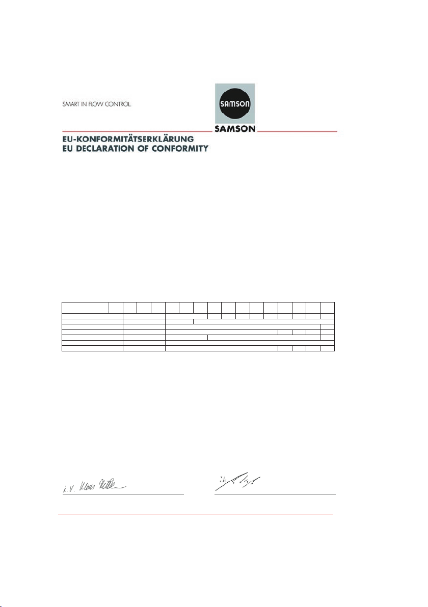
EU
Modul H/Module H, Nr./No. / N° CE-PED-H-SAM 001-13-DEU-rev-A
SAMSON erklärt in alleiniger Verantwortung für folgende Produkte:/For the following products, SAMSON hereby declares
under its sole responsibility:
Ventile für Druck-, Differenzdruck-, Temperatur- und Volumenstromregler/Valves for pressure,
temperature, flowregulators and differential pressure regulators
Typ 2336, 2373, 2375, 44-1B, 44-2, 44-3, 44-4, 44-6B, 44-9, 45-1, 45-2, 45-3, 45-4, 45-6, (Erz.-Nr. 2720), 45-9, 47-4, 2488, 2489, (2730),
2405, 2406, 2421 (2811), 2412 (2812), 2417 (2817), 2422 (2814), 2423 (2823), 2423E (2823)
die Konformität mit nachfolgender Anforderung/the conformit y with the following requirement
Richtlinie des Europäischen Parlaments und des Rates zur Harmonisierung der Rechtsvorschriften
der Mitgliedstaaten über die Bereitstellung von Druckgeräten auf dem Markt.
Directive of the European Parliament and of the Council on the harmonization of the laws of the
Member States relating of the making available on the market of pressure equipment (see also
Articles 41 and 48).
Angewandtes Konformitätsbewertungsverfahren für Fluide nach Art. 4(1)(c.i) erster Gedankenstric h.
Conformity assessment procedure applied for fluids according to Article 4(1)(c.i), first indent See table for
Nenndruck
Pressure rating
PN 16 ohne/without
PN 25 ohne/without
PN 40 ohne/without
PN 100 und PN 160 ohne/without
Class 150 ohne/without
Class 300 ohne/without
Class 600 und Class 900 ohne/ without
(1) Das auf dem Stellgerät aufgebrachte CE-Zeichen hat keine Gültigkeit im Sinne der Druckgeräterichtlinie.
The CE marking affixed to the control valve is not valid in the sense oft the Pressure Equipment Directive.
(2) Das auf dem Stellgerät aufgebrachte CE-Zeichen gilt ohne Bezeichnung der benannten Stelle (Kenn-Nr. 0062).
The CE marking affixed to the control valve is valid without specifying the notified body (ID number 0062).
(3) Die Identifikationsnummer 0062 von Bureau Veritas S.A. gilt nicht für Modul A.
The identification number 0062 of Bureau Veritas S.A. is not valid for Modul A.
Geräte, denen laut Tabelle das Konformitätsbewertungsverfahren Modul H zugrunde liegt, beziehen sich auf die
„Zulassungsbescheinigung eines Qualitätssicherungssystems“ ausgestel lt durch die benannte Stelle.
Devices whose conformity has been assessed based on Module H refer to the certificate of approval for the quality management system
issued by the notified body
Dem Entwurf zu Grunde gelegt sind Verfahren aus:/The design is based on the methods of:
DIN EN 12516-2, DIN EN 12516-3 bzw./or ASME B16.1, ASME B16.24, ASME B16.34, ASME B16.42
Das Qualitätssicherungssystem des Herstellers wird von folgender benannter Stelle überwacht:
The manufacturer’s quality management system is monitored by t he following notified body:
Bureau Veritas S.A. Nr./No. 0062, Newtime, 52 Boulevard du Parc, IIle de la Jatte, 92200 Neuilly sur Seine, France
NPS
.
Hersteller:/Manufacturer: SAMSON AG, Weismüllerstraße 3, 60314 Frankfurt am Main, Germany
1¼ 401½ 502 65- 803
(1)
(2)(3)
A
(1)
A
(1)
(1)
H - - - -
(1)
A
(1)
(1)
H - - - -
- - - - - - - - -
(2)(3)
(2)(3)
Frankfurt am Main, 08. Februar 2017/08 February 2017
2014/68/EU vom 15.05.2014
2014/68/EU of 15 May 2014
Modul siehe
Tabelle
module
H
H -
H
durch
certified by
Bureau Veritas
S. A. (0062)
10
12
16
Klaus Hörschken Dr. Michael Heß
Zentralabteilungsleiter / Head of Central Department Zentralabteilungsleiter / Head of Central Department
Entwicklung Ventile und Antriebe / R&D, Valves and Actuators P roduct Management & Technical Sales
-Konformitaetserklaerung_Blatt-08_ Modul-A_Modul-H_DE-EN_Rev.03_2017-02-08.docx
SAMSON AKTIENGESELLSCHAFT
Weismüllerstraße 3 60314 F rankfurt am Main
Telefon: 069 4009-0 · Telefa x: 069 4009-1507
E-Mail: samson@samson.de
Revision 03
38 EB 2723 EN
Page 39

DN
15½ 20¾ 251 32
1004 125- 1506 2008 250
300
400
H
H -
EU
Modul H/Module H, Nr./No. / N° CE-0062-PED-H-SAM 001-16-DEU-rev-A
SAMSON erklärt in alleiniger Verantwortung für folgende Produkte:/For the following products, SAMSON hereby declares
under its sole responsibility:
Ventile für Druck- Differenzdruck-, Volumenstrom- und Temperaturregler/Valves for pressure, differential pressure,
volume flow and temperature regulators
2333 (Erz.-Nr./Model No. 2333), 2334 (2334), 2335 (2335), 2336, 2373, 2375, 44-0B, 44-1B, 44-2, 44-3, 44-6B, 44-7, 44-8, 45-1, 45-2, 45-3,
45-4, 45-5, 45-6, 2468, 2478 (2720), 45-9, 46-5, 46-6, 46-7, 46-9, 47-1, 47-4, 47-5, 47-9, 2487, 2488, 2489, 2491, 2494, 2495 (2730), 2405,
2406, 2421 (2811), 2392, 2412 (2812), 2114 (2814), 2417 (2817), 2422 (2814), 2423 (2823)
die Konformität mit nachfolgender Anforderung/the conformit y with the following requirement.
Richtlinie des Europäischen Parlaments und des Rates zur Harmonisierung der Rechtsvorschriften
der Mitgliedstaaten über die Bereitstellung von Druckgeräten auf dem Markt.
Directive of the European Parliament and of the Council on the harmonization of the laws of the
Member States relating of the making available on the market of pressure equipment.
Angewandtes Konformitätsbewertungsverfahren für Fluide nach Art. 4(1)(c.ii) und (c.i) zweiter
Gedankenstrich.
Conformity assessment procedure applied for fluids according to Article 4(1)(c.ii) and (c.i ), second
indent
Nenndruck
Pressure rating
PN 16 ohne/without
PN 25 ohne/w ithout
PN 40 ohne/without
PN 100 und PN 160 ohne/without
Class 150 ohne/without
Class 300 ohne/without
Class 600 und Class 900 ohne/ without
(1) Das auf dem Stellgerät aufgebrachte CE-Zeichen hat keine Gültigkeit im Sinne der Druckgeräterichtlinie.
The CE marking affixed to the control valve is not valid in the sense of the Pressure Equipment Directive.
(2) Das auf dem Stellgerät aufgebrachte CE-Zeichen gilt ohne Bezeichnung der benannten Stelle (Kenn-Nr. 0062).
The CE marking affixed to the control valve is valid without specifying the notified body (ID number 0062).
(3) Die Identifikationsnummer 0062 von Bureau Veritas S.A. gilt nicht für Modul A.
The identification number 0062 of Bureau Veritas S.A. is not valid for Modul A.
Geräte, denen laut Tabelle das Konformitätsbewertungsverfahren Modul H zugrunde liegt, beziehen sich auf die
„Zulassungsbescheinigung eines Qualitätssicherungssystems“ ausgestel lt durch die benannte Stelle.
Devices whose conformity has been assessed based on Module H refer to the certificate of approval for the quality management system
issued by the notified body
Dem Entwurf zu Grunde gelegt sind Verfahren aus:/The design is based on the procedures specified in the following standards:
DIN EN 12516-2, DIN EN 12516-3 bzw./or ASME B16.1, ASME B16.24, ASME B16.34, ASME B16.42
Das Qualitätssicherungssystem des Herstellers wird von folgender benannter Stelle überwacht:
The manufacturer’s quality management system is monitored by t he following notified body:
Bureau Veritas S.A. Nr./No. 0062, Newtime, 52 Boulevard du Parc, IIle de la Jatte, 92200 Neuilly sur Seine, France
NPS
.
Hersteller:/Manufacturer: SAMSON AG, Weismüllerstraße 3, 60314 Frankfurt am Main, Germany
1¼ 401½ 502 65- 803
(1)
A
(1)
A
(1)
(2)(3)
A
(1)
H -
(1)
A
(1)
(2)(3)
A
(1)
H -
(2)(3)
(2)(3)
H
(2)(3)
H -
Frankfurt am Main, 08. Februar 2017/08 February 2017
2014/68/EU vom 15.05.2014
2014/68/EU of 15 May 2014
Modul siehe
Tabelle
See table for
module
durch
certified by
Bureau Veritas
S. A. (0062)
10
12
H
16
Klaus Hörschken Dr. Michael Heß
Zentralabteilungsleiter/Head of Central Department Zentralabteilungsleiter/Head of Central Department
Entwicklung Ventile und Antriebe/R&D, Valves and Actuators Product Managem ent & Technical Sales
-Konformitaetserklaerung_Blatt-04_ Modul-A_Modul-H_DE-EN_Rev.03_2017-02-08.docx
SAMSON AKTIENGESELLSCHAFT
Weismüllerstraße 3 60314 F rankfurt am Main
Telefon: 069 4009-0 · Telefa x: 069 4009-1507
E-Mail: samson@samson.de
Revision 03
EB 2723 EN 39
Page 40

Modul D/Module D, Nr./No. / N° CE-0062-PED-D-SAM 001-16-DEU-rev-A
SAMSON erklärt in alleiniger Verantwortung für folgende Produkte:/For the following products, SAMSON hereby declares
under its sole responsibility:
Sicherheitsüberströmventil SÜV 44-4 (2720-03)/Safety Excess Pressure Valve SEV 44-4 (2720-03)
die Konformität mit nachfolgender Anforderung/the conformit y with the following requirement.
Richtlinie des Europäischen Parlaments und des Rates zur Harmonisierung
der Rechtsvorschriften der Mitgliedstaaten über die Bereitstellung von
Druckgeräten auf dem Markt.
Directive of the European Parliament and of the Council on the
harmonization of the laws of the Member States relating of the making
available on the market of pressure equipment.
EG-Baumusterprüfbescheinigung
EC Type Examination Certificate
Angewandtes Konformitätsbewertungsverfahren
Conformity assessment procedure applied
Dem Entwurf zu Grunde gelegt sind Verfahren aus:/The design is based on the procedures specified in the following standards:
DIN EN 12516-2, DIN EN 12516-3 bzw./or ASME B16.24, ASME B16.42
Das Qualitätssicherungssystem des Herstellers wird von folgender benannter Stelle überwacht:
The manufacturer’s quality management system is monitored by t he following notified body:
Bureau Veritas S.A. Nr./No. 0062, Newtime, 52 Boulevard du Parc, IIle de la Jatte, 92200 Neuilly sur Seine, France
Hersteller:/Manufacturer: SAMSON AG, Weismüllerstraße 3, 60314 Frankfurt am Main, Germany
Frankfurt am Main, 08. Februar 2017/08 February 2017
2014/68/EU vom 15.05.2014
2014/68/EU of 15 May 2014
Modul B
Module B
Modul D
Module D
Zertifikat-Nr./Certificate no.
01 202 931-B-13-0029
Zertifikat-Nr./Certificate no.
CE-0062-PED-D-SAM-001-16-DEU-rev-A
Klaus Hörschken Dr. Michael Heß
Zentralabteilungsleiter/Head of Central Department Zentralabteilungsleiter/Head of Central Department
Entwicklung Ventile und Antriebe/R&D, Valves and Actuators Product Managem ent & Technical Sales
-Konformitaetserklaerung_Blatt-28_ Modul-B_und_Modul-D_DE-EN_Rev.03_2017-02-08.docx
SAMSON AKTIENGESELLSCHAFT
Weismüllerstraße 3 60314 F rankfurt am Main
Telefon: 069 4009-0 · Telefa x: 069 4009-1507
E-Mail: samson@samson.de
Revision 03
40 EB 2723 EN
Page 41

Modul D/Module D, Nr./No. / N° CE-0062-PED-D-SAM 001-16-DEU-rev-A
SAMSON erklärt in alleiniger Verantwortung für folgende Produkte:/For the following products, SAMSON hereby declares
under its sole responsibility:
Sicherheitsüberströmventil SAV 44-8 (2720-02)/Safety Excess Pressure Valve SSV 44-8 (2720-02)
die Konformität mit nachfolgender Anforderung/the conformit y with the following requirement.
Richtlinie des Europäischen Parlaments und des Rates zur Harmonisierung
der Rechtsvorschriften der Mitgliedstaaten über die Bereitstellung von
Druckgeräten auf dem Markt.
Directive of the European Parliament and of the Council on the
harmonization of the laws of the Member States relating of the making
available on the market of pressure equipment.
EG-Baumusterprüfbescheinigung
EC Type Examination Certificate
Angewandtes Konformitätsbewertungsverfahren
Conformity assessment procedure applied
Dem Entwurf zu Grunde gelegt sind Verfahren aus:/The design is based on the procedures specified in the following standards:
DIN EN 12516-2, DIN EN 12516-3 bzw./or ASME B16.24, ASME B16.42
Das Qualitätssicherungssystem des Herstellers wird von folgender benannter Stelle überwacht:
The manufacturer’s quality management system is monitored by t he following notified body:
Bureau Veritas S.A. Nr./No. 0062, Newtime, 52 Boulevard du Parc, IIle de la Jatte, 92200 Neuilly sur Seine, France
Hersteller:/Manufacturer: SAMSON AG, Weismüllerstraße 3, 60314 Frankfurt am Main, Germany
2014/68/EU vom 15.05.2014
2014/68/EU of 15 May 2014
Modul B
Module B
Modul D
Module D
Zertifikat-Nr./Certificate no.
01 202 931-B-13-0027
Zertifikat-Nr./Certificate no.
CE-0062-PED-D-SAM-001-16-DEU-rev-A
Frankfurt am Main, 08. Februar 2017/08 February 2017
Klaus Hörschken Dr. Michael Heß
Zentralabteilungsleiter/Head of Central Department Zentralabteilungsleiter/Head of Central Department
Entwicklung Ventile und Antriebe/R&D, Valves and Actuators Product Managem ent & Technical Sales
-Konformitaetserklaerung_Blatt-22_ Modul-B_und_Modul-D_DE-EN_Rev.03_2017-02-08.docx
SAMSON AKTIENGESELLSCHAFT
Weismüllerstraße 3 60314 F rankfurt am Main
Telefon: 069 4009-0 · Telefa x: 069 4009-1507
E-Mail: samson@samson.de
Revision 03
EB 2723 EN 41
Page 42

42 EB 2723 EN
Page 43

EB 2723 EN 43
Page 44

EB 2723 EN
SAMSON AKTIENGESELLSCHAFT
Weismüllerstraße 3 · 60314 Frankfurt am Main, Germany
Phone: +49 69 4009-0 · Fax: +49 69 4009-1507
samson@samson.de · www.samson.de
2019-03-19 · English
 Loading...