

Sammic CA-401 Installation Manual
INSTRUCCIONES - USERS MANUAL - GEBRAUCHSANWEISUNG MODE D’EMPLOI - INSTRUZIONI PER L’USO - MANUAL DE INSTRUÇÕES
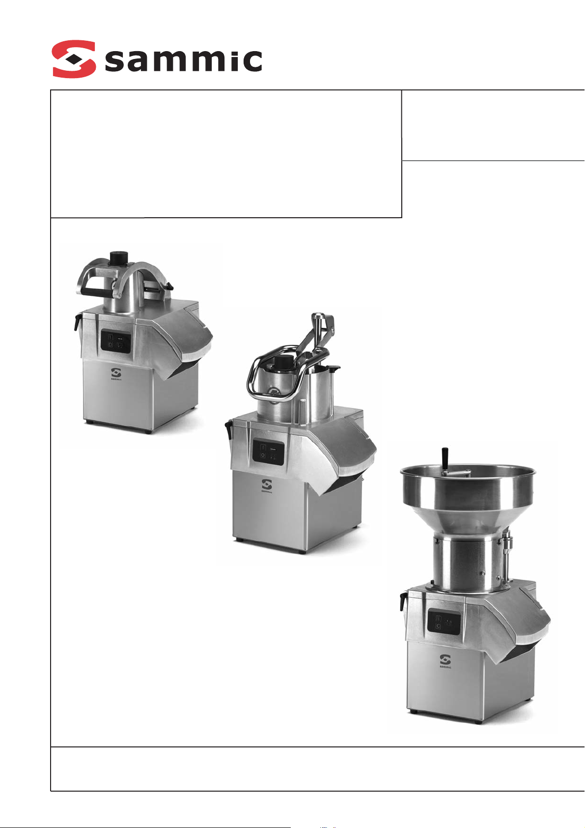
Cortadoras de hortalizas
Vegetable preparation machine
Gemüseschneidemaschine
Coupe-légumes
Tagliatrice di ortaggi
Cortadora de hortaliças
CA-301
CA-401
CA-601
Cada máquina lleva las siguientes indicaciones:
- Nombre y dirección del fabricante: SAMMIC
S.L - Basarte 1 Azkoitia. Gipuzkoa (SPAIN)
- El número de serie se indica en la hoja de
garantía y en la declaración de conformidad.
MODELOS
Este manual describe la instalación, funcionamiento y mantenimiento de las Cortadoras de
Hortalizas CA-301, CA-401 y CA-601. La referencia del modelo y sus características se indican en la placa de identificación colocada en la
máquina. Esta cortadora está diseñada y fabricada de acuerdo con las directivas Europeas:
- Directiva de máquinas 2006/42/CE.
- Directiva de baja tensión 2006/95/CE.
- Directiva de compatibilidad electromagnética
2004/108/CE.
- Directivas de materiales de aluminio y plásticos alimentarios 89/109/CEE y 90/128/CEE.
- Norma de aleaciones de aluminio moldeadas
en contacto con alimentos EN 601-2004.
- Norma de higiene y materiales alimentarios:
ANSI-NSF 8 y ANSI-NSF 51.
- Norma Cortadoras de Hortalizas: UNE-EN 1678.
- Índice de protección según la norma UNE-EN
60529: Mandos IP-55 y el resto de maquina
IP-23.
- Los modelos de 120V/60Hz/1~ cumplen con
las normas UL-763 y CSA C22.2.
INSTALACION
Para obtener las mejores prestaciones y una
buena conservación de la máquina, siga las
instrucciones contenidas en este manual.
EMPLAZAMIENTO
Se recomienda colocar la cortadora sobre una
superficie estable -que no actúe como caja de
resonancia- a una altura comprendida entre
700-900 mm para la CA-301, 600-800 mm para
la CA-401 y 500-700 para la CA-601. Colocar el
recipiente de recuperación por debajo de la
boca de salida de los alimentos. La máquina no
está sujeta y es fácilmente desplazable.
CONEXION ELECTRICA
Comprobar que las características eléctricas
de la maquina coinciden con el de la red.
Cortadoras monofásicas: 230V / 50 Hz / 1;
220V / 60 Hz / 1; 120V / 60 Hz / 1.
Preparar una toma de corriente mural, que sea
siempre accesible, con interruptor general de
seccionamiento, y con protección diferencial y
magneto-térmica de 2P de 16 A con su clavija
correspondiente.
Cortadoras trifásicas: 230-400V / 50 Hz / 3N
(conectado a 400V); 220-380V / 60 Hz / 3N
(conectado a 220V).
Preparar una toma de corriente mural, que sea
siempre accesible, con interruptor general de
seccionamiento, y con protección diferencial y
magneto-térmica de 4P de 10 A con su clavija
correspondiente.
Para cambiar de voltaje seguir las indicaciones
del esquema eléctrico.
Sentido de giro: Cuando el sentido de giro de la
cortadora no es el correcto, el disco (A) no corta.
El disco (A) debe girar en sentido antihorario. Si el
giro del disco (A) es horario, para invertirlo intercambiar dos fases en el cable de alimentación.
Características del cable.
Las Cortadoras CA-301, CA-401 y CA-601 se
suministran con un cable eléctrico de 1,5 m de
largo, con recubrimiento termo plástico.
ATENCION: ES OBLIGATORIA LA CONEXION A TIERRA. PELIGRO DE ELECTROCUCION. El hilo de toma-tierra de la máquina
es el de color amarillo-verde.
FUNCIONES DEL CONTROL ELECTRONICO
Y SU FUNCIONAMIENTO
Ver Fig. 1.
Piloto “Maquina en tensión” (1).
Al conectar la cortadora a la red, este piloto se
enciende indicando que la cortadora esta alimentada.
Ver Fig. 1.
Pulsador de “Marcha” (3) o velocidad lenta
en modelo 2 velocidades.
CA-301 y CA-401:
- Con la tapa articulada (I) cerrada y pisador (L)
abajo, si pulsamos esta tecla el motor arranca.
En los modelos de 2 velocidades arranca en la
velocidad lenta.
- Con el motor parado, tapa articulada (I) cerrada
y pisador (L) arriba, si pulsamos esta tecla, el
piloto “seguridad” (2) parpadea. Al bajar el pisador (L) el motor arranca.
- Con el motor en marcha si subimos el pisador
(L) el motor se para. Al bajar el pisador (L) el
motor vuelve a arrancar automáticamente. Si
en 30 sg no se ha bajado el pisador (L) es
necesario volver a pulsar el pulsador de
“Marcha” (3) para poder arrancar la maquina.
- Con el motor en marcha si se abre la tapa articu-
lada (I) el motor se para. Al cerrar la tapa articulada (I) es necesario volver a pulsar el pulsador
de “Marcha” (3) para poder arrancar la maquina.
- Si se deja la maquina en marcha con el pisa-
dor (L) abajo a los 30 minutos la maquina se
para automáticamente.
CA-601 y cabezal de tubos:
- Con el motor parado, la tolva montada y la
tapa articulada (I) cerrada, si pulsamos esta
tecla, el motor arranca.
- Con el motor en marcha si se abre la tapa articulada (I) el motor se para. Al cerrar la tapa articulada (I) es necesario volver a pulsar el pulsador
de “Marcha” (3) para poder arrancar la maquina.
Ver Fig. 1.
Pulsador de “Velocidad 2” (7). Velocidad
rápida. Solo modelos 2 velocidades.
El funcionamiento de esta tecla es idéntica a la
tecla de “Marcha” (3). Lo único que la maquina
arranca a velocidad rápida.
Ver Fig. 1.
Pulsador de “Parada” (4).
La pulsación de esta tecla para el motor.
Ver Fig. 1.
Piloto “Seguridad” (2).
Este piloto nos da información sobre el estado
de la cortadora.
- Con motor parado, tapa articulada (I) cerrada
y pisador (L) abajo esta apagado.
- Con motor en marcha, tapa articulada (I)
cerrada y pisador (L) abajo esta encendido.
- En la CA-301 y CA-401 con tapa articulada (I)
cerrada y pisador (L) arriba parpadea lentamente.
- Con tapa articulada (I) abierta parpadea con
rapidez.
Ver Fig. 1.
Piloto “Velocidad 1” (5). Solo modelos 2
velocidades.
Este piloto nos da información sobre el estado
de la cortadora cuando arranca a la velocidad
lenta.
- Con motor parado, tapa articulada (I) cerra-
da y pisador (L) abajo esta apagado.
- Con motor en marcha, tapa articulada (I)
cerrada y pisador (L) abajo esta encendido.
- En la CA-301 y CA-401 con tapa articulada (I)
cerrada y pisador (L) arriba parpadea lentamente.
- Con tapa articulada (I) abierta parpadea con
rapidez junto con el piloto de “velocidad 2” (6).
2
ES

3
ES
Ver Fig. 1.
Piloto “Velocidad 2” (6). Solo modelos 2
velocidades.
Este piloto nos da información sobre el estado de
la cortadora cuando arranca a la velocidad rápida.
- Con motor parado, tapa articulada (I) cerrada
y pisador (L) abajo esta apagado.
- Con motor en marcha, tapa articulada (I)
cerrada y pisador (L) abajo esta encendido.
- En la CA-301 y CA-401 con tapa articulada (I)
cerrada y pisador (L) arriba parpadea lentamente.
- Con tapa articulada (I) abierta parpadea con
rapidez junto con el piloto de “velocidad 2” (6).
NOTA: En la CA-601 no existe pisador y su
lugar en la maniobra lo ocupa la tolva (U).
PUESTA EN MARCHA CA-301 Y CA-401
- En la CA-301 y CA-401 es necesario colocar
la tapa articulada (I) según se indica en los
dibujos, fijándolos con el pasador (N).
- En la CA-301 es necesario colocar el pisador
(L) según se indica en los dibujos fijándolos
con el pasador (O).
- En la CA-301 y CA-401si se quiere utilizar el cabe-
zal de tubos es necesario colocarla según se indica en los dibujos, fijándolos con el pasador (N).
ATENCION: Antes de utilizar por primera vez
la máquina, limpiar la zona de contacto con
alimentos, los discos (A), las rejillas (B) y el
expulsor (C) con agua jabonosa (templada),
aclarar y dejarla secar.
Los discos (A) y rejillas (B) están provistos
de cuchillas muy afiladas, por tanto hay que
manipularlas cuidadosamente.
Colocación de discos (A) y rejillas (B).
- Desbloquear el cierre (H), y abrir la Tapa arti-
culada (I).
- Colocar el expulsor (C) en su alojamiento del
eje de arrastre.
- La rejilla (B) se inserta en la cavidad de la tapa
inferior (E) cuando el proceso lo requiera.
- Colocar un disco (A) en el eje de arrastre.
Para ello introducir el disco (A) en el eje y
girarlo en sentido horario hasta que queda
encajado en el eje de arrastre.
- En la CA-401 roscar en el eje de arrastre la
broca (P) o el revolvedor (R) según el producto a cortar.
- Bajar la tapa articulada (I) y bloquear el cierre (H).
Funcionamiento con la tolva normal (J) y
pisador (L) en la CA-301.
- Es necesario que el mazo (K) este alojado y
bloqueado en su orificio. Esto se hace girándolo en el sentido antihorario.
- Poner en marcha la cortadora.
- Levantar el pisador (L). El motor se para.
- Introducir los productos en la tolva normal (J).
- Al empezar a bajar el pisador (L) el motor arranca y empieza el proceso de corte. Empujar el
producto bajando suavemente el pisador (L).
Repetir la operación una y otra vez.
- Pulsar “Parada” (4) al terminar la producción.
ATENCION: Hacer una fuerza de apriete
excesiva sobre el pisador (L) puede deteriorar el producto y forzar el motor en exceso.
Funcionamiento con la tolva normal (J) de
entrada y pisador (L) en la CA-401.
- Es necesario que el mazo (K) este alojado y
bloqueado en su orificio. Esto se hace girándolo en el sentido antihorario.
- Poner en marcha la cortadora.
- Levantar el pisador (L) y girarlo en sentido
antihorario para liberar la zona de introducción
de alimentos de la tolva normal (J). El pisador
(L) se puede dejar apoyado sobre el soporte
pisador (M). El motor se para.
- Introducir los productos en la tolva normal (J).
- Al girar el pisador (L) en sentido horario el
motor arranca y empieza el proceso de corte.
Empujar el producto bajando suavemente el
pisador (L). Repetir la operación una y otra
vez.
- Pulsar “Parada” (4) al terminar la producción.
ATENCION: Hacer una fuerza de apriete
excesiva sobre el pisador (L) puede deteriorar el producto y forzar el motor en exceso.
Funcionamiento con tolva cilíndrica (K) (CA301 y CA-401)
Esta tolva de Ø55mm se utiliza para el corte de
productos cilíndricos y alargados, como las
zanahorias, endivias, pepinos, etc.
- Poner en marcha la cortadora.
- Desbloquear el mazo (K) girándolo en el sentido horario.
- Introducir los productos por el orifico y empujarlos suavemente con el mazo (K). Repetir la
operación una y otra vez.
- Pulsar “Parada” (4) al terminar la producción.
IMPORTANTE: Cuando no se utiliza la tolva
cilíndrica, dejar el mazo (K) dentro de la tolva.
PUESTA EN MARCHA CA-601
ATENCION: Antes de utilizar por primera vez
la máquina, limpiar la zona de contacto con
alimentos, los discos (A), las rejillas (B) y el
expulsor (C) con agua jabonosa (templada),
aclarar y dejarla secar.
Los discos (A) y rejillas (B) están provistos
de cuchillas muy afiladas, por tanto hay que
manipularlas cuidadosamente.
Colocación de discos (A) y rejillas (B).
- Colocar el expulsor (C) en su alojamiento del
eje de arrastre.
- La rejilla (B) se inserta en la cavidad de la tapa
inferior (E) cuando el proceso lo requiera.
- Colocar un disco (A) en el eje de arrastre.
Para ello introducir el disco (A) en el eje y
girarlo en sentido horario hasta que queda
encajado en el eje de arrastre.
- Roscar en el eje el revolvedor (R).
- Colocar la tapa articulada (I) como se indica
en los dibujos. Fijarla con el pasador (N) y bloquear la con el cierre(H).
- Colocar la tolva (U) como se indica en los
dibujos. En los tres alojamientos del cuello de
la tapa articulada (I) tienen que introducirse
los tres enganches de la tolva (U). Además
introducir el eje guía de la tolva (U) en su alojamiento, situado en la tapa articulada (I) y
bloquearla girando el pasador de seguridad.
Funcionamiento de la CA-601.
NOTA: Los agujeros de la tolva son de Ø75
mm, por tanto introducir producto (patata)
calibrado inferior a esa medida.
- Es necesario que la tolva este montada y bloqueada.
- Poner en marcha la cortadora.
- Ir introduciendo los productos por los agujeros
superiores de la tolva (J). A los 30 minutos la
CA-601 automáticamente se para. Si se quiere seguir trabajando volver a pulsar marcha.
- Si se producen atascos girar la manivela
situada en la parte superior de la tolva (U).
- Pulsar “Parada” (4) al terminar la producción.
Funcionamiento de la CA-301, CA-401 y CA601 con cabezal de tubos.
- Es necesario que el cabezal de tubos este
montado y bloqueado. Repetir todos los pasos
anteriores pero en la CA-401 y CA-601 no hay
que montar ni la broca (P) ni el revolvedor (R).
- Poner en marcha la cortadora.
- Ir introduciendo los productos por los agujeros
superiores del cabezal de tubos. A los 30
minutos la cortadora automáticamente se
para. Si se quiere seguir trabajando volver a
pulsar macha.
- Pulsar “Parada” (4) al terminar la producción.
LIMPIEZA CA-301, CA-401 Y CABEZAL DE TUBOS
ATENCION: Desconectar la cortadora de la red
antes de cualquier manipulación en su interior.
Los discos (A) y rejillas (B) están provistos
de cuchillas muy afiladas, por tanto hay que
manipularlas cuidadosamente.
Todos los elementos de la cortadora que están
en contacto con los alimentos se deben limpiar
inmediatamente después de su utilización, con
agua caliente y un detergente admitido en ali-

mentación. Después aclarar con abundante
agua caliente y desinfectar con un paño suave
impregnado en alcohol etílico (90 º).
Para ello:
- Desbloquear el cierre (H), y abrir la tapa articulada (I).
- En la CA-401, sujetando el disco (A) con la
mano sin tocar las cuchillas, utilizar la llave (S)
suministrada junto con la maquina para desmontar la broca (P) o el revolvedor (R), desenroscándolo en sentido antihorario.
- Retirar el disco (A) girándolo en sentido hora-
rio y tirando de el hacia arriba cuidadosamente. Retirar la rejilla (B) y el expulsor (C).
- En la CA-301 es posible desmontar el pisador
(L) y la lapa articulada (I) para facilitar su limpieza. Para ello desmontar los pasadores (N y O) .
LIMPIEZA CA-601
ATENCION: Desconectar la cortadora de la red
antes de cualquier manipulación en su interior.
Los discos (A) y rejillas (B) están provistos
de cuchillas muy afiladas, por tanto hay que
manipularlas cuidadosamente.
Todos los elementos de la cortadora que están
en contacto con los alimentos se deben limpiar
inmediatamente después de su utilización, con
agua caliente y un detergente admitido en alimentación. Después aclarar con abundante
agua caliente y desinfectar con un paño suave
impregnado en alcohol etílico (90 º).
Para ello:
- Quitar la tolva (U). Girar el pasador de seguridad y tirar de la tolva (U) hacia arriba.
- Desbloquear el cierre (H), tirar del pasador (N)
para quitar la tapa articulada (I).
- Sujetando el disco (A) con la mano sin tocar las
cuchillas, utilizar la llave (S) suministrada junto
con la maquina para desmontar el revolvedor
(R), desenroscándolo en sentido antihorario.
- Retirar el disco (A) girándolo en sentido horario
y tirando de el hacia arriba cuidadosamente.
- Retirar la rejilla (B) y el expulsor (C).
LIMPIEZA GENERAL
- El exterior de la máquina NO SE DEBE lim-
piar con un chorro directo de agua.
Emplear para su limpieza un paño húmedo y
cualquier detergente habitual. NO SE DEBEN
utilizar detergentes abrasivos (aguafuerte,
lejía concentrada etc..) ni estropajos o ras-
quetas que contengan acero común, pueden
causar la oxidación de la máquina.
- No introducir en un lavavajillas las piezas des-
montables como discos (A), rejillas (B), tapa
articulada (I) y pisador (L).
ATENCION: Para poder retirar los productos encajados en las rejillas (B) basta golpearlas con una patata alargada o una
zanahoria entera en el sentido de corte. De
esta forma no se daña la rejilla (B). Tener
precaución con el filo de la rejilla (B).
Nunca utilizar objetos duros para golpear
la rejilla (B).
Funcionamiento de discos (A) y rejillas (B).
Discos (A):
- Discos (A) FC-1 y FC-2 para cortar patatas
“chips” o rodajas finas de 1 y 2 mm.
- Discos (A) de FC-3 a FC-25 para obtener
rodajas de 3 a 25 mm de patatas, zanahorias,
remolachas, coles, pepinos, calabacines,
cebollas, rábanos, etc.
- Discos (A) con cuchilla curva, para productos
blandos, FCC-2, FCC-3 y FCC-5 para cortar
en rodajas tomate, naranja, limón, plátano,
manzana, etc.
- Discos (A) ralladores tipo FR, desde 2 á 7
mm, para deshilar verduras y rallar queso,
pan, nueces, almendras, etc.
- Para cortar patatas del tipo “paja” y “cerilla”,
tiras de zanahorias, apio, remolacha, etc., discos (A) FCE-2 , FCE-4 y FCE-8.
- Discos (A) FR-1 y FR-8 para rallar el pan,
queso, chocolate, etc.
Discos (A) y rejillas (B). Combinaciones
posibles:
- Los discos (A) FC-6, FC-8, FC-10 combinadas con las rejillas (B), FFC-8 y FFC-10 se
obtienen patatas del tipo “fritas”.
- Los discos (A) FC-3, FC-6, FC-8, FC-10 y FC14 combinados con las rejillas (B) FMC-8 y
FMC-10 se obtienen dados y/o cubos de 3 a
14 mm de patatas para tortillas, de hortalizas
y frutas para macedonia, ensalada rusa, etc.
- Los discos (A) FC-20 y FC-25 combinados
con las rejillas FMC-20 y FMC-25 se obtienen
dados y/o cubos de 20x20 y 25x25.
Broca (P) y Revolvedor (R). Solo en la CA-401.
- Broca (P): Es utilizada exclusivamente para
trabajos en col o similares. Gracias a ella es
posible cortar piezas enteras.
- Eje revolvedor (R): Hay que utilizarlo con
todos los productos menos la col y similares.
Expulsor alto y normal (C). Solo en la CA-401.
- Expulsor alto: Para corte de productos voluminosos como la col, la coliflor, el apio y para el
rallado de productos como queso, zanahorias...
- Expulsor normal: Resto de cortes.
MANTENIMIENTO
PRECAUCIONES IMPORTANTES
- Antes de cualquier intervención para la
limpieza, revisión o reparación de las cortadoras es obligatorio desconectar la
máquina de la red.
- No introducir NUNCA la mano ni cualquier
utensilio por las bocas de salida o tolvas (J y
K)de entrada de la cortadora, a fin de evitar
accidentes o el deterioro de las cuchillas.
- Verificar periódicamente el funcionamiento de
las seguridades de la cortadora. En caso de
detectar alguna anomalía llamar al servicio
técnico reconocido por SAMMIC.
- Verificar periódicamente el estado del reten
del eje de arrastre para preservar la estanqueidad de esta zona. Cada vez que se suelte el eje de arrastre para mantenimiento se
recomienda colocar un reten nuevo.
- Limpiar la cortadora después de cada uso tal
y como se ha descrito con anterioridad.
- Si el cable de alimentación se deteriora y es
preciso instalar uno nuevo, dicho recambio
sólo podrá ser realizado por un servicio técnico reconocido por SAMMIC.
- Nivel de ruido de la máquina, en marcha, colocada a 1,6 m de altura y 1 m de distancia, inferior a 70 dB(A). Ruido de fondo:32 dB(A).
AFILADO DE CUCHILLAS
ATENCION: Los discos (A) y rejillas (B)
están provistos de cuchillas muy afiladas,
por tanto hay que manipularlas cuidadosamente.
Las cuchillas de los discos (A) se desmontan
fácilmente para poder afilarse. Para su afilado
emplear siempre piedras blandas conservando
el ángulo de corte de la cuchilla.
INCIDENCIAS DE FUNCIONAMIENTO
Estando la tapa articulada (I) cerrada y el pisador (L) abajo pulsando marcha la cortadora no
arranca:
- La cortadora esta conectada y el piloto
“Maquina en tensión” (1) esta apagado. No
llega alimentación a la placa o la placa esta
estropeada.
- En la CA-301 y CA-401 si el piloto “Seguridad”
(2) parpadea lentamente con el pisador (L)
abajo hay algún problema en el micro de
seguridad del pisador (L). En la CA-601 y
Cabezal de tubos también puede darse este
aviso. En las maquinas de 2 velocidades el
parpadeo se da en los pilotos “Velocidad 1” (5)
o “Velocidad 2” (6).
- Si el piloto “Seguridad” (2) parpadea con rapidez con la tapa articulada (I) cerrada hay
algún problema en el micro de seguridad de la
tapa articulada (I). En las maquinas de 2 velocidades el parpadeo se da en los pilotos
“Velocidad 1” (5) o “Velocidad 2” (6).
4
ES

- Si el piloto “Maquina en tensión” (1) y
“Seguridades” (2) parpadean alternándose, la
protección térmica del motor ha actuado.
Esperar hasta que se rearme y verificar que
ha podido pasar ( carga de trabajo excesiva,
piezas agarrotadas, en modelos monofásicos
problemas del relé arranque o condensadores...). En los modelos de 2 velocidades el
parpadeo se da entre el piloto “Maquina en
tensión” (1) y “velocidad 1” (5) si la velocidad
seleccionada era la lenta. O el piloto “Maquina
en tensión” (1) y “velocidad 2” (6) si la velocidad seleccionada era la rapida.
- Para verificar que el teclado funciona correctamente, si mantenemos pulsada durante 2 sg
una de las teclas el piloto “Maquina en tensión” (1) parpadea. Si esto no se da puede
haber algún problema en el teclado.
La cortadora estaba en marcha y se ha parado
sin pulsar ninguna tecla. Si estando la maquina
en marcha sin actuar sobre el pisador (L) la
maquina se para automáticamente a los 30
minutos.
Nota: En la CA-601 no hay pisador por tanto
a los 30 minutos la maquina se para automáticamente. Para volver a arrancar la
maquina solo hay que pulsar marcha (3).
Nota: La placa electrónica tiene los siguientes pilotos e indicadores:
- Power: Se enciende si hay tensión en la placa.
- SEG: Se enciende si todas las seguridades
están cerradas.
- RL1, RL2, RL3: Se encienden cuando el relé
correspondiente cierra su contacto.
- Interruptor SW1: Posición OFF cortadora 1
velocidad. Posición ON cortadora 2 velocidades.
- Fus1-Var1: La placa tiene un fusible y un
varistor de protección.
Al bajar el pisador el motor no arranca:
- Si se deja el pisador (L) abierto mas de 30 Sg
es necesario volver a pulsar “Marcha” (3)
para rearmar la cortadora.
- En la CA-301 puede que la tolva esta demasiado llena y el pisador no actúa sobre el micro.
Vaciar parte de la tolva he intentarlo de nuevo.
Si el ruido de la cortadora es excesivo o el disco
(A) roza en alguna parte, es probable que los rodamientos del eje principal se hayan deteriorado.
OTRAS OBSERVACIONES IMPORTANTES
- Este aparato no esta destinado para ser
usado por personas (incluido niños) cuyas
capacidades físicas, sensoriales o mentales
estén reducidas, o carezcan de experiencia o
conocimiento, salvo si han tenido supervisión
o instrucciones relativas al uso del aparato por
una persona responsable de su seguridad.
- Esta maquina es de uso vigilado no dejar
nuca la maquina en marcha sin que nadie
este al cargo de ella.
5
ES
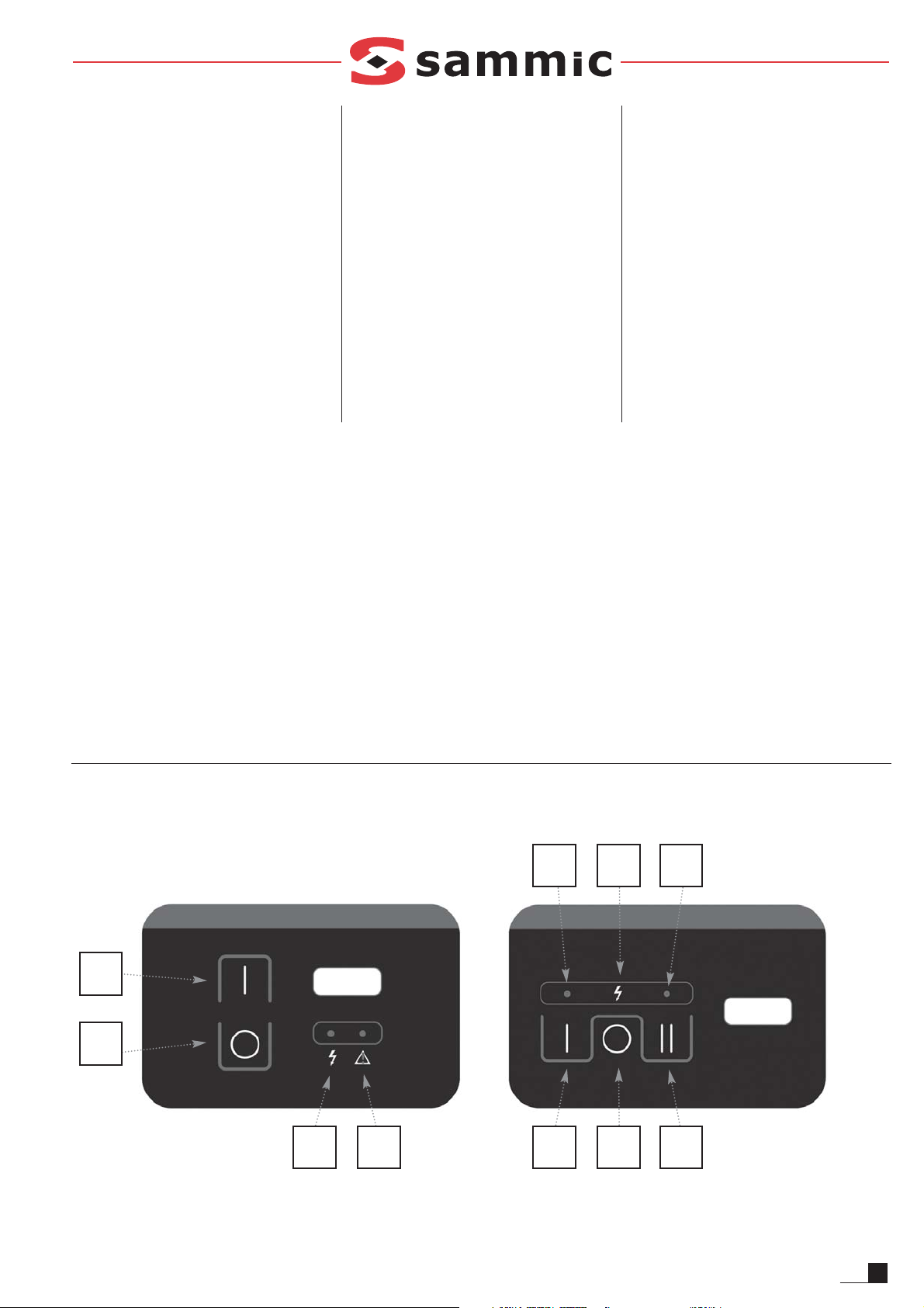
FIG. 1
3
4
1 2 3 4 7
5 1 6

Each machine is identified as follows:
- Name and address of the manufacturer: SAMMIC S.L - Basarte 1 Azkoitia. Gipuzkoa (SPAIN)
- The serial number is printed on the Guarantee
Card and in the Declaration of Conformity.
MODELS
This manual describes the installation, operation and maintenance of vegetable preparation
machines CA-301, CA-401 and CA-601. The
model reference number and its features are
specified on the name plate attached to the
machine. This preparation machine has been
designed and manufactured in accordance with
the following European directives:
- Machinery Directive 2006/42/EC.
- Low Voltage Directive 2006/95/EC.
- Electromagnetic Compatibility Directive
2004/108/EC.
- Directives 89/109/EEC and 90/128/EEC on
aluminium and plastic materials and articles in
contact with food.
- Aluminium alloys in contact with food standard
EN 601-2004.
- Hygiene and food contact materials standard:
ANSI-NSF 8 and ANSI-NSF 51.
- Vegetable Preparation Machines Standard:
UNE-EN1678
- Protection level in accordance with UNE-EN
60529: Controls IP-55 and rest of machine IP-23.
- The 120V/60Hz/1~ models comply with the
UL-763 and CSA C22.2 standards
INSTALLATION
For optimum service and maintenance, please
follow these instructions.
INSTALLATION SITE
You are advised to install the machine on a
steady surface -this must not act as a soundboard- elevated at a height of 700-900 mm for
CA-301, 600-800 mm for CA-401 and 500-700
mm for CA-601. Place the collector underneath
the food outlet. The machine is not fixed in
place and can be moved around easily.
ELECTRICAL CONNECTION
Check that the machine’s electrical characteristics match the mains power supply.
Single-phase machines: 230V / 50 Hz / 1; 220V
/ 60 Hz / 1; 120V / 60 Hz / 1.
Prepare a wall-mounted socket that is always
accessible, with a general disconnecting switch
and with a residual current and 2P, 16 A circuit
breaker, with its corresponding plug.
Three-phase machines: 230-400V / 50 Hz / 3N
(connected to 400V); 220-380V / 60 Hz / 3N
(connected to 220V).
Prepare a wall-mounted socket that is always
accessible, with a general disconnecting switch
and with a residual current and 2P, 10 A circuit
breaker, with its corresponding plug.
To change the voltage, refer to the electrical
diagram.
Direction of rotation: When the machine’s direction of rotation is incorrect, the disc (A) will not
cut. The disc (A) must rotate anti-clockwise. If
the disc (A) rotates clockwise, to reverse it
swap two phases in the power cable.
Power cable characteristics.
Vegetable preparation machines CA-301, CA401 and CA-601 are supplied with a 1.5 m thermoplastic-sheathed power cable.
WARNING: THE EARTH CONNECTION IS
OBLIGATORY. DANGER OF ELECTROCUTION.
The machine’s earth wire is yellow-green.
ELECTRONIC CONTROL FUNCTIONS AND
OPERATION
See Fig. 1.
“Machine connected to mains” warning light (1).
When the machine is plugged in, this warning
light switches on to show that the machine is
connected to the mains.
See Fig. 1.
“Start” button (3) or slow speed in the 2speed model.
CA-301 and CA-401:
- With the hinged lid (I) closed and the pusher plate
(L) down, if you push this button the motor starts.
In the 2-speed models it starts at slow speed.
- With the motor stopped, the hinged lid (I)
closed and the pusher plate (L) up, if you
press this button, the "safety" light (2) flashes.
When the pusher plate (L) is pressed down
the motor starts.
- With the motor stopped, the hinged lid (I)
closed and the pusher plate (L) up, if you
press this button, when the pusher plate is
lowered (L) the motor starts. In the 2-speed
models the pilot light “Speed 1” (5) flashes.
- With the motor on, if you lift the pusher plate
(L) the motor stops. When you lower the pusher plate (L), the motor re-starts automatically.
If the pusher plate (L) has not lowered in 30
seconds, the “Start” button (3) must be
pressed again to start the machine.
- With the motor on, if the hinged lid (I) is
opened the motor stops. When the hinged lid
(I) is closed, the “Start” button (3) needs to be
pressed again to start the machine.
- If the machine is left running with the pusher
plate (L) down, after 30 minutes the machine
stops automatically.
CA-601 and header:
- If this button is pressed whilst the motor is
switched off, the hopper mounted and the
hinged lid (I) closed, the motor starts.
- If the hinged lid (I) should open whilst the motor
is in operation the motor will stop. When closing
the hinged lid (I) the pushbutton “On” (3) must
be pressed again in order to start the machine.
See Fig. 1.
“Speed 2” button (7). Fast speed. Only 2speed models.
The operation of this button is identical to that of
the “Start” button (3). The only difference is that
the machine starts at high speed.
See Fig 1.
“Stop” button (4).
This button stops the motor.
See Fig 1.
“Safety” warning light (2).
This warning light shows the machine’s status.
- It switches off when the motor is stopped, the
hinged lid (I) is closed and the pusher plate (L)
is down.
- It switches on when the motor is stopped, the
hinged lid (I) is closed and the pusher plate (L) is up.
- In the CA-301 and CA-401 with the hinged lid (I)
closed and the pusher plate (L) up it flashes slowly.
- It flashes quickly when the hinged lid (I) is open.
See Fig. 1.
“Speed 1” pilot light (5). Only in the
2-speed models.
This pilot light provides information on the status of the vegetable preparation machine when
starting at slow speed.
- It switches off when the motor is stopped, the
hinged lid (I) is closed and the pusher plate (L)
is down.
- It switches on when the motor is on, the hinged
lid (I) is closed and the pusher plate (L) is down
- In the CA-301 and CA-401 with the hinged lid (I)
closed and the pusher plate (L) up it flashes slowly.
6
EN

7
EN
- It flashes quickly when the hinged lid (I) is
open in conjunction with the “Speed 2”pilot
light (6).
See Fig. 1.
“Speed 2”pilot light (6). Only in 2-speed
models.
This pilot light provides information on the status of the vegetable preparation machine when
starting at fast speed.
- It switches off when the motor is stopped, the
hinged lid (I) is closed and the pusher plate (L)
is down.
- It switches on when the motor is on, the hinged
lid (I) is closed and the pusher plate (L) is down
- In the CA-301 and CA-401 with the hinged lid
(I) closed and the pusher plate (L) up it flashes slowly.
- It flashes quickly when the hinged lid (I) is open in
conjunction with the “Speed 2”pilot light (6).
NOTE: In the CA-601 there is no pusher
plate and its place in the operation is taken
by the hopper (U).
START-UP CA-301 Y CA-401
- In the CA-301 and CA-401 the hinged lid (I)
must be positioned as indicated in the illustrations, being fixed with the pin (N).
- In the CA-301 the pusher plate (L) must be
positioned as indicated in the illustrations,
being fixed with the pin (O).
- In the CA-301and CA-401 if the header is to
be used it must be positioned as indicated in
the illustrations, being fixed with the pin (N).
WARNING: Before using the machine for the
first time, clean the area in contact with
food, the discs (A), the grids (B) and the
ejector (C) with (lukewarm) soapy water,
rinse and leave to dry.
Handle the discs (A) and grids (B) very carefully because they have very sharp blades.
Fitting discs (A) and grids (B).
- Release the lock (H), and open the hinged lid (I).
- Fit the ejector (C) in its housing on the trailing
axle.
- The grid (B) is inserted in the top lid (E) pock-
et at the right time during the process.
- Fit a disc (A) on the trailing axle. Insert the
disc (A) in the axle and rotate it clockwise until
it slots into place.
- In the case of the CA-401machine, screw the bit
(P) or mixer (R) into the trailing axle depending
on the product being chopped.
- Lower the hinged lid (I) and apply the lock (H).
Operation with standard hopper (J) and
pusher plate (L) in CA-301.
- The mallet (K) must be housed and locked. To
do so, rotate it anti-clockwise.
- Start the vegetable preparation machine.
- Lift the pusher plate (L). The motor stops.
- Add the products to the standard hopper (J).
- When you start to lower the pusher plate (L)
the motor starts and the cutting process
begins. Feed the product while gently lowering
the pusher plate (L). Repeat the process several times.
- Press “Stop” (4) to finish.
WARNING: Applying too much force on the
pusher plate (L) could damage the product
and strain the motor.
Operation with standard feed hopper (J) and
pusher plate (L) in CA-401.
- The mallet (K) must be housed and locked. To
do so, rotate it anti-clockwise.
- Start the vegetable preparation machine.
- Lift the pusher plate (L) and rotate it anti-clockwise to clear the standard hopper (J) feed
chute. The pusher plate (L) can be left resting
on the pusher support (M). The motor stops.
- Add the products to the standard hopper (J).
- When the pusher plate (L) is rotated clockwise
the motor starts and the cutting process
begins. Feed the product while gently lowering
the pusher plate (L). Repeat the process several times.
- Press “Stop” (4) to finish.
WARNING: Applying too much force on the
pusher plate (L) could damage the product
and strain the motor.
Operation with cylinder hopper (K) (CA-301
and CA-401).
This Ø55mm hopper is used to cut long, cylinder-shaped vegetables, such as carrot, chicory,
cucumber, etc.
- Start the vegetable preparation machine.
- Unlock the mallet (K) by rotating it clockwise.
- Feed the vegetables through the hole and
push them gently using the mallet (K). Repeat
the process several times.
- Press “Stop” (4) to finish.
IMPORTANT: When the cylinder hopper is
not in use, leave the mallet (K) inside the
hopper.
START-UP OF CA-601
WARNING: Before using the machine for the
first time, clean the area in contact with
food, the discs (A), the grids (B) and the
ejector (C) with (lukewarm) soapy water,
rinse and leave to dry.
Handle the discs (A) and grids (B) very carefully because they have very sharp blades.
Fitting discs (A) and grids (B).
- Fit the ejector (C) in its housing at the trailing
edge.
- The grid (B) is inserted in the bottom lid (E)
pocket at the right time during the process.
- Fit a disc (A) on the trailing axle. Insert the
disc (A) in the axle and rotate it clockwise until
it slots into place.
- Screw on the mixer axle (R):
- Fit the hinged lid (I) as indicated in the diagrams. Secure it with the pin (N) and block it
with the lock (H).
- Place the hopper (U) as indicated in the diagrams. The three hooks of the hopper (U)
must be inserted in the three spaces in the
neck of the hinged lid (I). Also insert the guiding axle of the hopper (U) in its housing, located on the hinged lid (I) and block it by rotating
the safety pin.
Operation of the CA-601.
NOTE: The holes in the hopper are Ø75 mm,
therefore insert products (potatos) smaller
than this size.
- The hopper must be mounted and locked.
- Start up the cutting machine.
- Gradually introduce the products via the top
holes in the hopper (J). After 30 minutes the
CA-601 stops automatically. If you wish to
continue working press “On” again.
- If there is jamming turn the handle at the top of
the hopper (U).
- Press “Off” (4) when finishing production.
Operation of the CA-301, CA-401 and CA-601
with header.
- The pipe manifold must be mounted and locked.
Repeat all the above processes. In the CA-401
and CA-601 there is no need to assemble the bit
(P) nor the mixer (R).
- Start up the cutting machine.
- Gradually introduce the products via the top
holes in the header. After 30 minutes the cutting machine stops automatically. If you wish
to continue working press “On” again.
- Press “Off” (4) when finishing production.
CLEANING CA-301, CA-401 AND PIPE HEADER
WARNING: Disconnect the machine from the
mains before handing any internal components.
Handle the discs (A) and grids (B) very carefully because they have very sharp blades.
- Any components in contact with the food must
be cleaned immediately after use, using hot
water and a food-safe detergent. Then rinse
with plenty of hot water and disinfect using an
ethyl alcohol-soaked cloth (90 º).

To do so:
- Release the lock (H), and open the hinged lid
(I).
- In the case of the CA-401 machine, while hold-
ing the disc without touching the blades, use
the Allen key supplied with the machine to
remove the bit (P) or mixer (R), unscrewing it
anti-clockwise.
- Remove the disc (A) by rotating it clockwise
and pulling it upwards carefully. Remove the
grid (B) and ejector (C).
- In the CA-301 machine the pusher plate (L)
and hinged lid (I) can be removed for cleaning.
To do so, remove the pins (N and O).
CLEANING CA-601
WARNING: Disconnect the machine from
the mains before handing any internal components.
Handle the discs (A) and grids (B) very carefully because they have very sharp blades.
Any components in contact with the food must
be cleaned immediately after use, using hot
water and a food-safe detergent. Then rinse
with plenty of hot water and disinfect using an
ethyl alcohol-soaked cloth (90 º).
To do so:
- Remove the hopper (U). Rotate the safety pin
and pull the hopper (U) upwards.
- Release the lock (H), pull the pin (N) to remove the hinged lid (I).
- Holding the disc (A) with your hand without
touching the blades, use the key (S) supplied
with the machine to remove the mixer (R),
unscrewing it anti-clockwise.
- Remove the disc (A) by rotating it clockwise
and pulling it upwards carefully.
- Remove the grid (B) and ejector (C).
GENERAL CLEANING
- NEVER power clean. Use a damp cloth and
mild detergent for cleaning. DO NOT use
abrasive detergents (nitric acid, neat
bleach, etc.) or stainless steel scourers or
scrubbers as they could cause rusting.
- Do not wash the parts, such as the discs (A),
grids (B), hinged lid (I) and pusher plate (L), in
a dishwasher.
WARNING: To remove food stuck in the
grids (B) you can knock them through
using an elongated potato or whole carrot
in the cutting direction. This avoids damaging the grid (B). Take care with the edge of
the grid (B). Never use hard objects to hit
the grid (B).
Disc (A) and grid (B) functions.
Discs (A):
- Discs (A) FC-1 and FC-2 to cut chips or fine
slices measuring 1-2 mm.
- Discs (A) FC-3 to FC-25 to cut 3-25 mm slices
of potato, carrot, beetroot, cabbage, cucumber, courgette, onion, radish, etc.
- Discs (A) with curved blade for soft food, FCC2, FCC-3 and FCC-5 to cut slices of tomato,
orange, lemon, banana, apple, etc.
- Shredding discs (A) FR, 2-7 mm, to shred vegetables and grate cheese, bread, nuts,
almonds, etc.
- Discs FCE-2, FCE-4 and FCE-8 to cut potato
“matchsticks”, carrot, celery, beetroot strips,
etc.
- Discs (A) FR-1 and FR-8 to grate bread,
cheese, chocolate, etc.
Discs (A) and grids (B). Possible combinations:
- Discs (A) FC-6, FC-8, FC-10 combined with
grids (B), FFC-8 and FFC-10, give chip-style
potatoes.
- Discs (A) FC-3, FC-6, FC-8, FC-10 and FC-14
combined with grids (B) FMC-8 and FMC-10
make 3-14 mm cubed potatoes for omelettes,
vegetables and fruit for salads and Russian
salad, etc.
- Discs (A) FC-20 and FC-25 combined with
grids FMC-20 and FMC-25 give 20x20 and
25x25 cubes.
Bit (P) and Mixer (R). Only CA-401
- Bit (P): It is only used when working with cabbage
and similar vegetables. Whole pieces can be cut.
- Mixer (R): It must be used with any food
except cabbage and similar vegetables.
High and normal ejector (C). Only in the CA-
401.
- High ejector: For cutting large products such as
cabbage, cauliflower, celery and for grating products such as cheese, carrots...
- Normal ejector: All other cutting.
MAINTENANCE
IMPORTANT PRECAUTIONS
- Before undertaking any cleaning, inspection
or repair work on vegetable preparation
machines the machine must be unplugged
from the mains.
- NEVER insert your hand or any other utensil
through the outlets or hoppers (J and K) that
feed the machine, to avoid accidents or damages to the blades.
- Regularly check that the machine safety
devices are working. If you detect any anomaly, call the SAMMIC authorised technical
service.
- Regularly inspect the trailing axle seal to
ensure that this area is properly sealed. Each
time the trailing axle is released for maintenance it is recommendable to fit a new seal.
- Clean the machine after every use, as
described above.
- Only a SAMMIC authorised technical service
can replace the power cable if this is damaged.
- Machine noise level, while running, at a height
of 1.6 m and a distance of 1 m, less than 70
dB(A). Background noise: 32 dB(A).
BLADE SHARPENING
WARNING: Handle the discs (A) and grates
(B) very carefully because they have very
sharp blades.
The disc blades (A) can be removed easily for
sharpening. Always use soft stone to keep the
blade’s cutting angle intact.
TROUBLESHOOTING
The hinged lid (I) is closed and the pusher plate
(L) down but the machine does not start when
the “Start” button is pressed:
- The machine is connected and the “Machine
connected to mains” (1) warning light is on. No
power reaches the plate or the plate is broken.
- In the CA-301 and CA-401 if the “Safety”
warning light (2) flashes slowly with the pusher plate (L) down there is a problem with the
pusher plate (L) safety microswitch. This
warning could also be triggered in the CA-601
and header. In the 2-speed machines the flashing occurs in the “Speed 1” (5) or “Speed 2”
indicators (6).
- If the “Safety” warning light (2) flashes quickly
with the hinged lid (I) closed, there is a problem with the hinged lid (I) safety microswitch.
In the 2-speed machines the flashing occurs in
the “Speed 1” (5) or “Speed 2” indicators (6).
- If the “Machine connected to mains” (1) and
“Safety” (2) warning lights flash alternately, the
motor thermal protection device has tripped.
Wait for it to reset and investigate what the
problem could have been (overload, parts
seized up, problems with starter relay or
capacitors in single-phase models etc...). In
the 2-speed models the flashing occurs
between the pilot lights “Machine connected to
the mains” (1) and “Speed 1” (5) if the speed
selected was slow. Or, the pilot light “Machine
connected to the mains” (1) and “Speed 2” (6)
if the speed selected was fast.
- To check that the keypad works properly, if
you keep one of the keys pressed down the
8
EN
“Machine connected to mains” warning light
(1) should flash. If it does not the keypad may
be malfunctioning.
The machine was on and stopped without
pressing any key. If the machine is on, without
pressing the pusher plate (L) the machine stops
automatically after 30 minutes.
Note: In the CA-601 there is no pin, therefore
after 30 minutes the machine stops automatically. To restart the machine simply
press “On” (3).
NOTE: The electronic board has the following lights and indicators:
- Power: Lights up when there is voltage in the
board.
- SEG: Lights up if all the safety devices are
closed.
- RL1, RL2, RL3: They light up when the
corresponding relay closes its contact.
- Switch SW1: Position OFF cutter 1 speed.
Position ON cutter 2 speeds.
- Fus1-Var1: The board has a fuse and a pro-
tection varistor.
The motor does not start when the pusher plate
is pressed down:
- If the pusher plate (L) is left open for more
than 30 seconds, press “Start” (3) again to
reset the machine.
- In the CA-301 machine the hopper might be
too full and the pusher plate does not activate
the microswitch. Empty part of the hopper and
try again.
If the machine makes too much noise or the
disc (A) rubs against any part, the main axle
bearings are probably damaged.
OTHER IMPORTANT INFORMATION
- This machine is not designed for use by people (including children) with reduced physical,
sensory or mental capabilities or lacking the
necessary experience or knowledge, unless
they have received supervision or instructions
from a health and safety expert.
- This machine must not be left running unsupervised.
9
EN
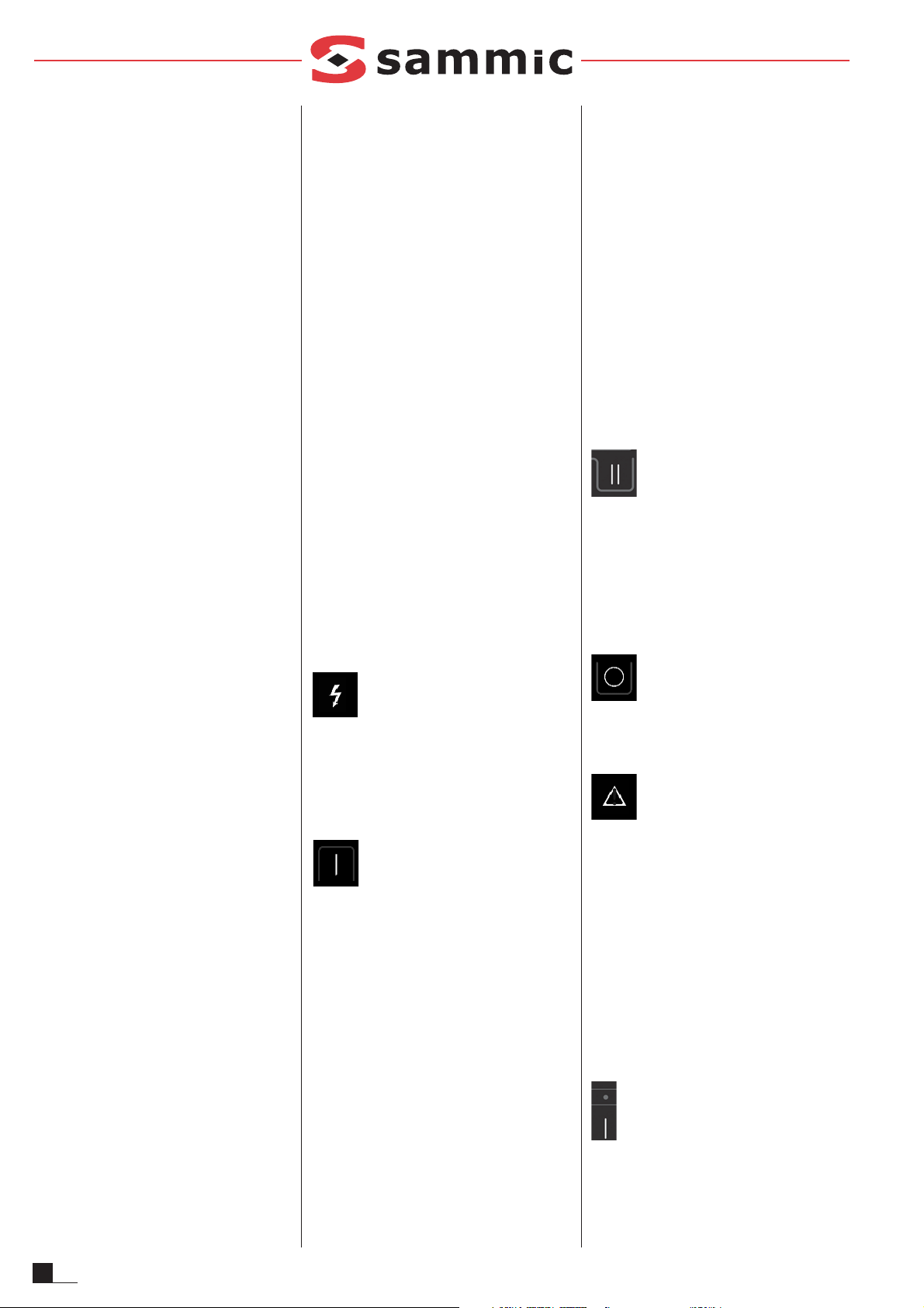
FIG. 1
3
4
1 2 3 4 7
5 1 6
Jede Maschine ist mit folgenden Angaben gekennzeichnet:
- Name und Anschrift des Herstellers: SAMMIC
S.L - Basarte 1 Azkoitia. Gipuzkoa (SPANIEN)
- Serien-Nr. auf dem Garantieschein und in der
Konformitätserklärung.
MODELLE
Dieses Handbuch enthält die Beschreibung für
das Aufstellen, den Betrieb und die Wartung der
Gemüseschneider CA-301, CA-401 und CA-601.
Die Referenznummer des Modells und seine technischen Eigenschaften sind auf dem Typenschild
des Geräts angegeben. Dieser Gemüseschneider
wurde in Einklang mit folgenden Europäischen
Richtlinien konstruiert und produziert:
- Richtlinie Maschinen: 2006/42/EU.
- Richtlinie Niederspannung: 2006/95/EU.
- Richtlinie Elektromagnetische Verträglichkeit:
2004/108/EU.
- Richtlinien Aluminium und Kunststoffe, die mit
Nahrungsmittel in Berührung kommen
89/109/EU und 90/128/EU.
- Norm für Aluminiumlegierungen, die mit
Nahrungsmitteln in Berührung kommen EN
601-2004.
- Norm für Hygiene- und Materialanforderungen
Nahrungsmittelindustrie ANSI-NSF 8 und ANSINSF 51.
- Norm für Gemüseschneider: UNE-EN 1678.
- Schutzklasse gemäß der Norm UNE-EN 60529:
Bedienelemente IP-55, übrige Teile des Geräts IP-23.
- Die Modelle mit 120V/60Hz/1~ erfüllen die
Normen UL-763 und CSA C22.2.
MONTAGE
Um die bestmögliche Leistung und eine lange
Lebensdauer der Maschine sicherzustellen, befolgen
Sie bitte genau die Hinweise dieser Betriebsanleitung.
STANDORT
Es wird empfohlen den Gemüseschneider auf
einer glatten Oberfläche abzustellen – die nicht
als Resonanzkörper wirkt – auf einer Höhe zwischen 700-900 mm für das Modell CA-301,
600-800 mm für CA-401 und 500-700 mm für
CA-601. Der Auffangbehälter muss unter dem
Nahrungsmittelauslass gestellt werden. Das
Gerät wird nicht befestigt und ist leicht an einen
anderen Ort zu bewegen.
ELEKTRISCHER ANSCHLUSS
Vergewissern Sie sich, dass die elektrischen
Anforderungen des Geräts von den
Eigenschaften des Netzes erfüllt werden.
Gemüseschneider mit Einphasenmotor: 230 V /
50 Hz / 1 ; 220 V / 60 Hz / 1 ; 120 V / 60 Hz / 1.
Sehen Sie eine stets zugängliche
Wandsteckdose mit Abschnittshauptschalter
und mit Fehlerstromschutz und thermo-magnetischem Schutzschalter mit 2P, 16 A sowie den
entsprechenden Stecker vor.
Gemüseschneider mit Dreiphasenmotor: 230-400
V / 50 Hz / 3 N (angeschlossen an 400 V); 220-380
V / 60 Hz / 3 N (angeschlossen an 220 V).
Sehen Sie eine stets zugängliche
Wandsteckdose mit Abschnittshauptschalter
und mit Fehlerstromschutz und thermo-magnetischem Schutzschalter mit 4P, 10 A sowie den
entsprechenden Stecker vor.
Nehmen Sie den Spannungswechsel wie im
elektrischen Schaltschema angezeigt vor.
Drehrichtung: Wenn die Drehrichtung des
Gemüseschneiders nicht korrekt ist, schneidet
die Scheibe (A) nicht. Die Scheibe (A) muss im
Gegenuhrzeigersinn drehen. Wenn die Scheibe
(A) im Uhrzeigersinn dreht, müssen zwei
Phasen im Netzkabel gegeneinander ausgetauscht werden.
Kabelanforderungen.
Die Gemüseschneider CA-301, CA-401 und CA601 werden mit einem 1,5 m langen Stromkabel
mit thermoplastischer Beschichtung geliefert.
ACHTUNG: DER ERDANSCHLUSS IST
PFLICHT. GEFAHR EINES STROMSCHLAGS.
Das Erdungskabel des Geräts ist gelb-grün.
FUNKTIONEN DER ELEKTRONISCHEN UND
BETRIEBSSTÖRUNGEN
Siehe Abb. 1.
Kontrolllampe “Gerät angeschlossen” (1).
Bei Anschluss des Gemüseschneiders schaltet
sich diese Kontrolllampe ein, um anzuzeigen,
dass der Gemüseschneider mit Strom versorgt
wird.
Siehe Abb. 1.
Einschalttaste (3) oder langsame
Geschwindigkeit beim Modell mit 2
Geschwindigkeitsstufen.
CA-301 und CA-401:
- Wenn die Klappe (I) geschlossen ist, sich der
Stößel (L) unten befindet und die Taste
gedrückt wird, startet der Motor. Bei den
Modellen mit 2 Geschwindigkeitsstufen erfolgt
der Start bei langsamer Geschwindigkeit.
- Wenn bei Motorstillstand die Klappe (I) geschlossen
ist, der Stößel (L) nach oben steht und die Taste
gedrückt wird, leuchtet die Kontrollleuchte
„Sicherheit“ (2) auf. Wenn der Stößel (L) nach
unten gedrückt wird, startet der Motor.
- Bei laufendem Motor stoppt der Motor, wenn der
Stößel (L) nach oben bewegt wird. Wenn der
Stößel (L) nach unten bewegt wird, startet der
Motor automatisch erneut. Wenn der Stößel (L)
innerhalb von 30 Sekunden nicht nach unten
bewegt wurde, muss die Einschalttaste (3)
gedrückt werden, damit das Gerät neu startet.
- Wenn die Klappe (I) bei laufendem Motor
geöffnet wird, stoppt der Motor. Wird die
Klappe (I) geschlossen, muss die
Einschalttaste (3) nochmals gedrückt werden,
damit das Gerät startet.
- Wenn Sie das Gerät mit dem nach unten
gedrückten Stößel (L) eingeschaltet lassen,
schaltet sich das Gerät nach 30 Minuten automatisch ab.
CA-601 und Schlauchkopfteil:
- Wenn der Trichter montiert und die Klappe (I)
geschlossen ist, und bei gestopptem Motor diese
Taste gedrückt wird, startet der Motor erneut.
- Wenn die Klappe (I) bei laufendem Motor geöffnet wird, stoppt der Motor. Wird die Klappe (I)
geschlossen, muss die Einschalttaste (3) nochmals gedrückt werden, damit das Gerät startet.
Siehe Abb. 1.
Schaltknopf für “Geschwindigkeit 2” (7).
Schnelle Geschwindigkeit. Nur bei Modellen
mit 2 Geschwindigkeitsstufen.
Die Funktion dieser Taste ist mit jener der Taste
„Betrieb“ (3) identisch. Der einzige Unterschied
besteht darin, dass die Maschine mit hoher
Geschwindigkeit startet.
Siehe Abb. 1.
Ausschalttaste (4).
Durch Drücken dieser Taste wird der Motor gestoppt.
Siehe Abb. 1.
Sicherheitskontrolllampe (2).
Diese Kontrolllampe gibt über den Zustand des
Gemüseschneiders Auskunft.
- Ist bei gestopptem Motor die Klappe (I)
geschlossen und der Stößel (L) unten, leuchtet die Kontrolllampe nicht.
- Ist bei laufendem Motor die Klappe (I)
geschlossen und der Schalter (L) unten,
leuchtet die Kontrolllampe.
- Ist bei den Modellen CA-301 und CA-401 die
Klappe (I) geschlossen und der Stößel (L)
unten, blinkt die Kontrolllampe langsam.
- Ist die Klappe (I) offen, blinkt sie schnell.
Siehe Abb. 1.
Betriebslampe “Geschwindigkeit 1” (5). Nur
bei Modellen mit 2 Geschwindigkeitsstufen.
Diese Betriebslampe dient zur Information über
den Status der Schneidemaschine, wenn diese
bei langsamer Geschwindigkeit startet.
10
DE
 Loading...