

Page 1

RT520 THERMOSTAT - FULL USER MANUAL
Page 2

TABLE OF CONTENTS
1. Introduction ...............................................................................................................................................................4
1.1 Product Compliance ......................................................................................................................................................................4
1.2 Safety Informations .......................................................................................................................................................................4
2. Product Overview .......................................................................................................................................................5
2.1 Example of boilers compatible with the OpenTherm OT+ 4.0 protocol ..........................................................................................6
2.2 Montage ........................................................................................................................................................................................7
2.3 Package content ............................................................................................................................................................................7
2.4 Proper thermostat location ...........................................................................................................................................................7
2.5 Connection description ..................................................................................................................................................................8
I A - Boiler connection ..........................................................................................................................................................8
I B - Pump / Valve connection ...............................................................................................................................................8
I C - KL08NSB underoor heating wiring center connection .................................................................................................8
3. Before you start (rst power up) ..................................................................................................................................9
3.1 LCD icon description ......................................................................................................................................................................9
3.2 Button description .........................................................................................................................................................................9
3.3 First power up sequence and conguration .................................................................................................................................10
3.4 OpenTherm - Hot Water conguration .........................................................................................................................................14
3.5 Max boiler temperature settings .................................................................................................................................................14
4. User settings ............................................................................................................................................................15
4.1 Manual mode ..............................................................................................................................................................................15
4.2 Schedule mode - programming schedule ....................................................................................................................................16
4.3 Switching between manual and schedule mode .........................................................................................................................17
4.4 BOOST mode - hourly temperature override (+Hr) ......................................................................................................................18
4.5 Control and Heat/Cool settings ....................................................................................................................................................19
4.6 OFFSET temperature calibration ..................................................................................................................................................20
4.7 Landlord settings ........................................................................................................................................................................21
4.8 Time/Date ...................................................................................................................................................................................23
4.9 Holiday mode ..............................................................................................................................................................................24
4.10 Language ..................................................................................................................................................................................25
5. Factory Reset ............................................................................................................................................................26
6. Error codes ...............................................................................................................................................................26
7. Battery change .........................................................................................................................................................26
8. Cleaning and Maintenance ........................................................................................................................................27
9. Technical Informations ..............................................................................................................................................27
10. Warranty ................................................................................................................................................................28
Page 3

Page 4

1. Introduction
1.1 Product Compliance
This product complies with the essential requirements and other relevant provisions of Directives 2014/53/EU and 2011/65/EU. The full text of the EU
Declaration of Conformity is available at the following internet address: www.saluslegal.com.
1.2 Safety Informations
• Before starting installation work and before using the product, read the entire manual.
• The information contained in the instructions is essential for proper functioning.
• To avoid accidents resulting in personal injury and material damage, please follow all safety precautions, specied in this manual.
• The device should not be used by people with limited mental, sensory or mental abilities, without experience, of insucient knowledge as well as
children.
• Do not use an unassembled device (eg without a cover).
• The device may only be opened by a qualied person.
• Keep electrical devices out of the reach of children and ensure that they do not play with it. Children should not be left unattended. If necessary,
disconnect the control system for the entire room.
• Do not leave the packaging, cabinet, or any loose parts of the device unattended, as they pose a risk to children.
WARNING!
• Installation must be carried out by a qualied person with appropriate electrical qualications in accordance with standards and regulations in force in
the given country and in the EU.
• Never try to connect the device other than as described in the manual.
• Before assembly, repair or maintenance as well as during any connection works it is absolutely necessary disconnect the mains supply and make sure
that the terminals and electric wires are not live.
• The device may not be exposed to extreme temperatures, strong vibrations or subjected to mechanical shock.
• The device should not be used in unfavorable environmental conditions or in rooms where there is a concentration of ammable gases, fumes or dust.
WARNING!
• There may be additional protection requirements for the entire installation that the installer is responsible for maintaining.
Care for the natural environment is of paramount importance to us. The awareness that we manufacture electronic devices obliges us
to dispose of used electronic components and devices safely. Therefore the company has received a registration number issued by the
Chief Inspector for Environmental Protection. The crossed out symbol the trash can on the product means that the product must not be
disposed of with ordinary waste containers. Sorting waste for recycling helps to protect the environment. It is the user’s responsibility
to surrender used equipment to a designated collection point for recycling waste from electrical and electronic equipment.
4
Page 5

2. Product Overview
The RT520 room thermostat simply switches the heating system on and o as necessary. It works by sensing the air temperature, switching on the heating
when the air temperature falls below the thermostat setting, and switching it o once this set temperature has been reached.
Turning a room thermostat to a higher setting will not make the room heat up any faster. How quickly the room heats up depends on the design of the
heating system, for example, the size of boiler and radiators. Neither does the setting aect how quickly the room cools down. Turning a room thermostat
to a lower setting will result in the room being controlled at a lower temperature, and saves energy.
The heating system will not work if a time switch or programmer has switched it o.
The way to set and use your room thermostat is to nd the lowest temperature setting that you are comfortable with, and then leave it alone to do its
job. The best way to do this is to set the room thermostat to a low temperature – say 18⁰C – and then turn it up by one degree each day until you are
comfortable with the temperature.
You won’t have to adjust the thermostat further. Any adjustment above this setting will waste energy and cost you more money.
If your heating system is a boiler with radiators, there will usually be only one room thermostat to control the whole house. But you can have dierent
temperatures in individual rooms by installing thermostatic radiator valves (TRVs) on individual radiators. If you don’t have TRVs, you should choose a
temperature that is reasonable for the whole house. If you do have TRVs, you can choose a slightly higher setting to make sure that even the coldest room
is comfortable, then prevent any overheating in other rooms by adjusting the TRVs.
Room thermostats need a free ow of air to sense the temperature, so they must not be covered by curtains or blocked by furniture. Nearby electric res,
televisions, wall or table lamps may prevent the thermostat from working properly.
Thermostat is compatibile with OpenTherm OT+ 4.0 version.
The OpenTherm protocol is an open standard communication protocol used in central heating systems for two-way communication between a central
heating boiler and a room thermostat. Thanks to the communication protocol, the boiler power is modulated, which can signicantly increase the energy
eciency of the heating system while maintaining the set temperature in the room. OpenTherm modulation, compared to standard communication (ON
/ OFF), occurs by setting the desired temperature of water from the boiler (boiler power), and not by its cyclical switching on and o.
PLEASE NOTE!
Make sure your gas combi boiler is compatible with OT + 4.0 communication protocol.
The list of compatible boilers is on the next page.
Product advantages:
• automatically detects OT + 4.0 protocol and regulates hot water temperature
• possibility to choose Hysteresis or built-in TPI algorithm for all types of heating
• works with time schedules
• service mode protected by a PIN code
• maximum / minimum temperature limitation
• can temporarily change the temperature (overwriting until the next program change)
5
Page 6

2.1 Example of boilers compatible with the OpenTherm OT+ 4.0 protocol
COMPANY MODEL
E-Tec S
E-tec Plus
Alpha Heating
E-tec
Evoke
Intec GS
iC
Atag
iC Economiser
iS
100 Combi
Baxi
200 Combi
400 Combi
600 Combi
D2CND 24Kw
Daikin
D2CND 28kw
D2CND 35kw
Ferroli
i25 Condensing Combination Boiler
i29 Condensing Combination Boiler
Independent + Combi
Independent Combi
Independent System
Logic Combi+ Combi C
Ideal
Logic Combi C24, C30, C35 (via a separate bundle set)
Logic Code Combi (via a separate bundle set)
I-mini C24, c30 (via a separate bundle set)
Vogue Combi C26,C32, C40
Logic + System
Logic + Heat
Intergas Rapid
Intergas Rapid Plus
Intergas
Combi Compact, Compact Range
ECO RF
Xtreme
Xclusive
COMPANY MODEL
Linea HE
Vokera
Mynute A
Mynute HE
Unica HE
Vitodens 100W Typ WB1A (Connection: X3.3 and X3.4)
Vitodens 100W Typ WB1B (Connection: X21.1 and
X21.2)
Vitodens 100W Typ WB1C (Connection: X21.1 and X21.2)
Viessmann
Vitodens 200-W WB2B 26+ 35 kW (via Expansion Module OT and OT-A8 + _Terminal -10 and +10 are on the
extension of the A8 boiler)
Vitodens 200-W WB2C, B2HA,B2JA, B2LA (via icm
Expander OpenTherm)
Vaillant
(via Vaillant
VR33 module)
Ecotec Pro
Ecotec Plus
Ecotec Exclusive
Ecot Pure
EMS capable boilers
Greenstar i
Greenstar i Junior (Made in July 2013)
Greenstar Si Compact
Greenstar CDi Compact
Worcester
Bosch
(via Net
EMS-OT
OpenTherm
converter)
Greenstar CDi Classic (Made after 16.01.2007 with
CF12.10 software version and newer)
Greenstar Highow CDi
Greenstar 12i System – 24i System (On condition that
an optional integrated diverter valve manufactured
after February 2011 is installed)
Greenstar 27i System – 30i System (Provided the optional Integrated Changeover Valve is installed Greenstar
CDi Classic System (provided the optional Integrated
Changeover Valve manufactured after 02/16/2007 with
software version CF12.10 and above is installed))
6
Main Eco Compact Combi 25-30
Navien Navien NCB
Avanta, Quinta Ace
Ravenheat
Quinta Pro
Gas 110 Eco
Evolve C
Evolve S
Linea One (przez OpenTherm Kit Part_1221179)
Vision Combi (requires a control interface 294501430
Compact A (requires a control interface 29450143)
Vokera
Verve (only heating mode)
Mynute I (only heating mode)
Vision System (only heating mode)
Unica I
Vibe
Vision C
Page 7

2.2 Montage
2.3 Package content
1) RT520 thermostat
2) Back housing
3) 2x AA batteries
4) Short instruction
5) Mounting screws
2.4 Proper thermostat location
1
4
5
32
Please note:
The ideal position to thermostat mounting is about 1,5m under oor level far from heating or cooling sources. Thermostat can’t be
exposed to sunlight or any extreme conditions like for example draft.
Because of re and explosion risk there is not allowed to use thermostat in atmosphere of explosive gases and ammable liquids (eg coal dust). In case
if any of listed dangers occur you have to use additional protection measures – anti-dust and explosive gases (tight cover) or prevent their formation.
Furthermore, thermostat can’t be used in condensation of water vapor conditions and be exposed to water action.
7
Page 8
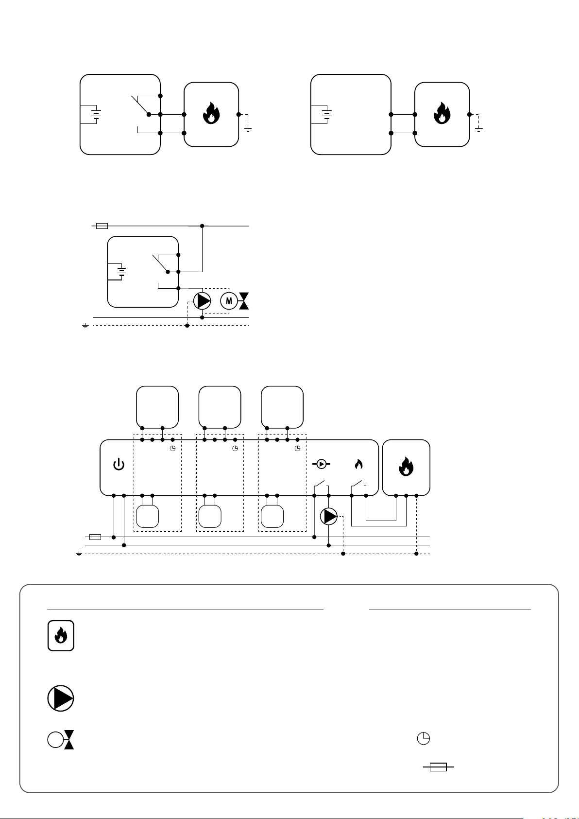
2.5 Connection description
B
A
RT520
OPENTHERM*
3V
2 x AA
AC 230V
I A - Boiler connection
RT520
NC
3V
2 x AA
COM
NO
PODŁĄCZENIE KOTŁA *
BOILER CONNECTION*
(ON / OFF) OpenTherm
I B - Pump / Valve connection
L
RT520
RT310
lub
3V
2 x AA
N
COM
NC
MAX
3 (1) A
NO
I C - KL08NSB underoor heating wiring center connection
RT520
3V
2 x AA
A
B
OPENTHERM*
Eg. Eg. Eg.
RT520 RT520 RT520
COM NO
KL08NSB
AC 230V
L
N
Power
L
L N SL
1 - 8 Zones 1 - 8 Zones 1 - 8 Zones
N
L N
T30NC
or lub
max 6
per zone
Legend: Symbols explanation:
Boiler - Boiler connection*
- Boiler’s contacts for ON/OFF
thermostat (according to the
boiler’s instructions)
COM NO
L N SL
L N
T30NC
max 6
per zone
COM NO
L N SL
L N
T30NC
max 6
per zone
Pump
1 2
Boiler
3 4
BOILER CONNECTION*
L, N - power supply 230V
NO, COM, NC - voltage-free output
A, B - OpenTherm Communication Wire
8
Pump
SL - 230V AC voltage output
M
Valve
- NSB function
- fuse
Page 9
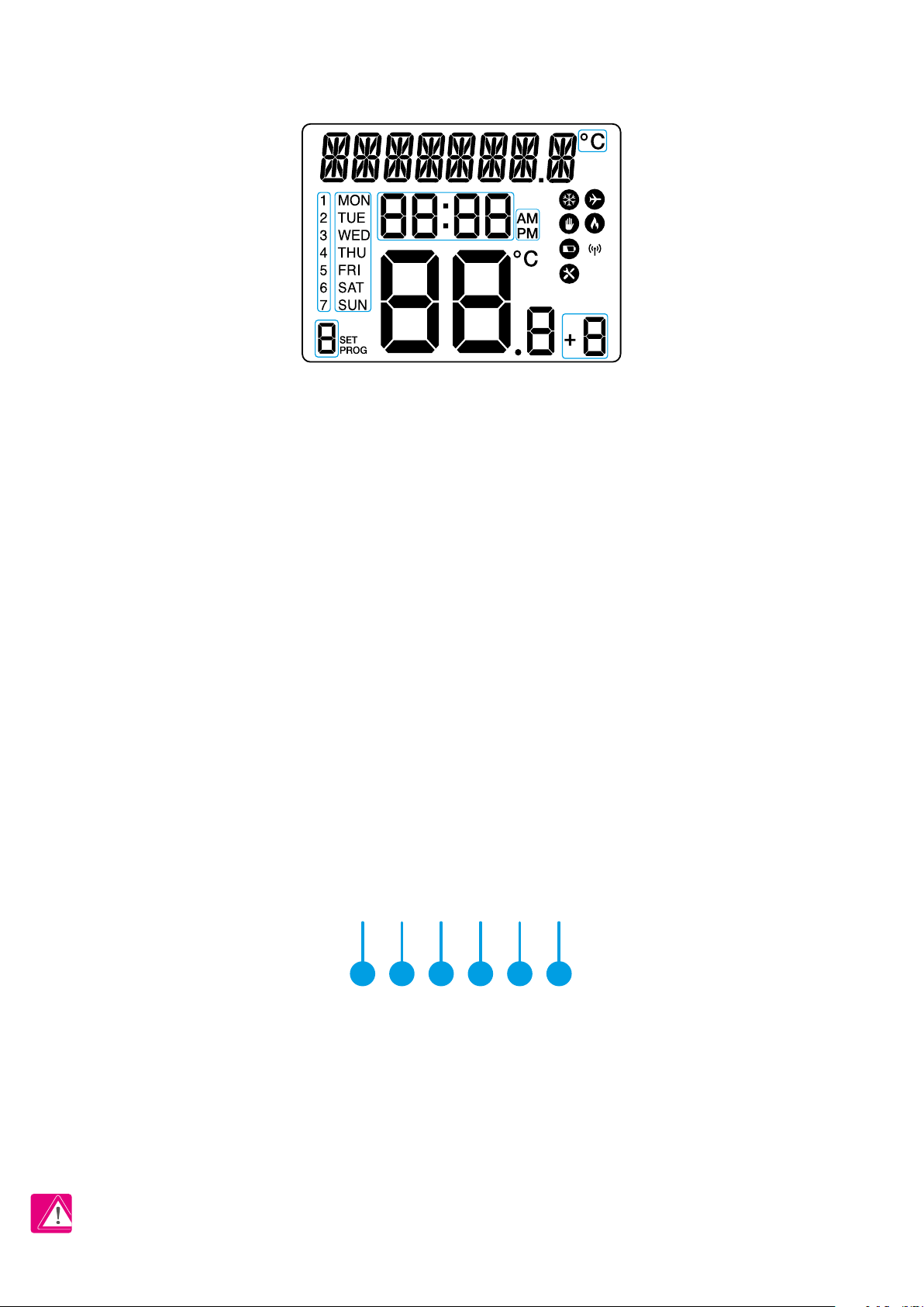
3. Before you start (rst power up)
3.1 LCD icon description
1
4
3B
3A
13
14
15
16
1. Text Bar
2. Temperature Unit
3A. Day of the week (numeric)
3B. Day of the week (alphabetic)
4. Clock
5. AM / PM
6. Cooling Mode On
7. Holiday Mode On
8. Manual Mode On
2
7
6
5
8
10
12
9
11
17
9. Heating Mode On
10. Low battery status
11. Wireless connection with the receiver
12. Service Mode On
13. Temperature measured / set
14. Program number
15. Settings
16. Program indicator
17. Boost function
3.2 Button description
1 2 3 4 5 6
1. MENU / RETURN - enter the menu options,
press and hold for 3 sec to return to main screen
or to deactivate Boost or Manual modes.
2. SELECT - conrm changes and enter menus.
3. DOWN - decrease the temperature and
move through the menus.
4. UP - increase the temperature and move
through menus.
5. BOOST - activate Boost Mode.
6. MANUAL - press once to activate / press and
hold for 3 sec to deactivate Manual Mode.
PLEASE NOTE! The LCD screen can be activated by using any button.
9
Page 10
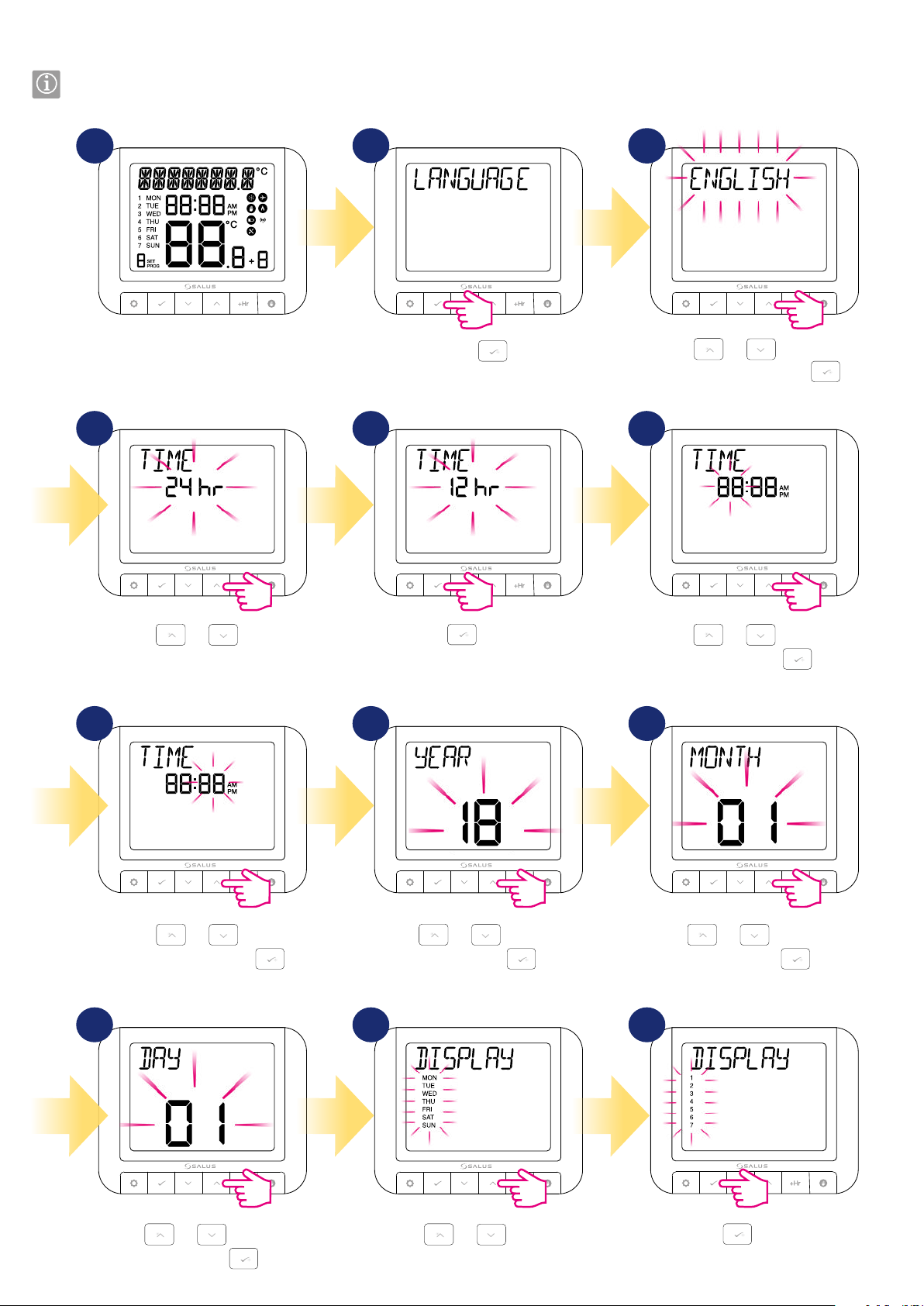
3.3 First power up sequence and conguration
Please make the receiver connections and power the receiver before inserting the batteries into the thermostat.
1
After inserting the batteries, the
thermostat will power up.
2
Press .
3
4 5 6
Using
language and then press .
or , choose your
Using
the time format.
or , choose
Press
to conrm.
7 8 9
Using
minutes and then press
or , set the
.
Using
and then press
or , set the year
.
10 11 12
Using
Using
or , set the hour
and then press
or , set the month
and then press
.
.
10
Using
and then press
or , set the day
.
Using
or , select the
week format.
Press
to conrm.
Page 11
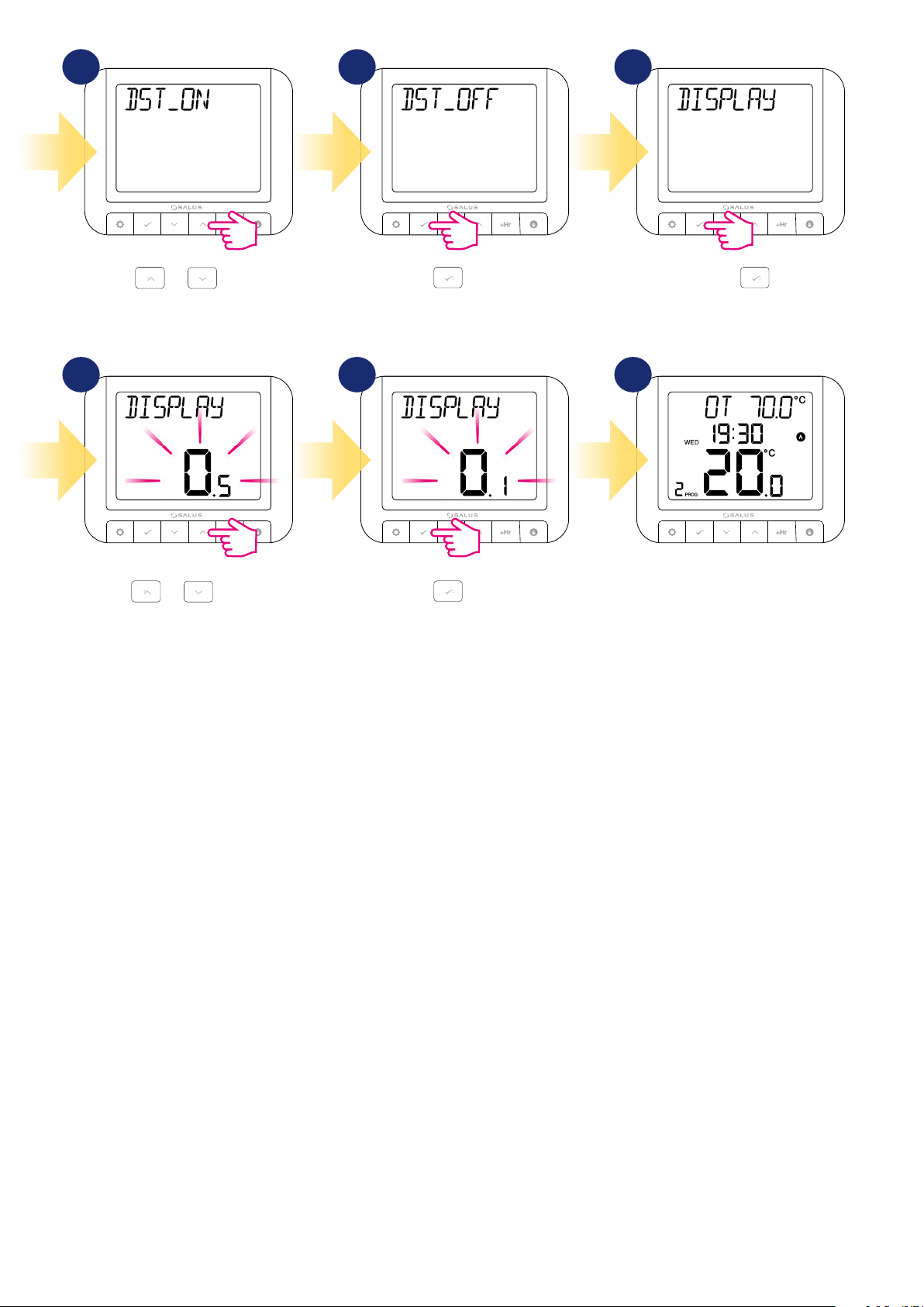
13 14 15
Using or , enable or
disable DST (Daylight Saving Time).
Using
or , select your
temperature accuracy.
Press
Press
to conrm. Press .
181716
to conrm.
When OpenTherm is connected, the
device software will automatically
adjust to the OpenTherm settings.
11
Page 12
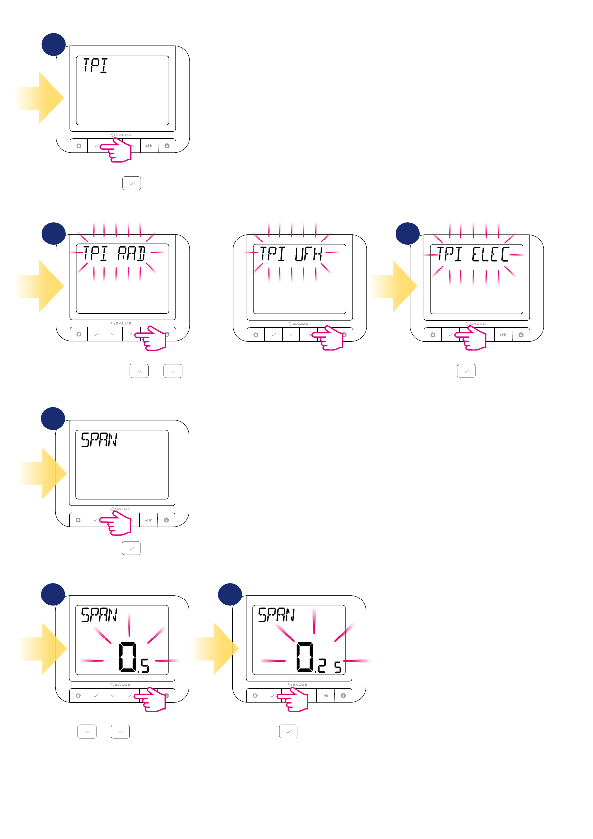
19
Press .
TPI (Time Proportional & Integral) is a self-learning, time-proportional algorithm.
TPI type of regulation ensures economical system operation through more accurate
temperature maintenance during controlling process and limits overload conditions.
In addition to the exact and stable room temperature, the advantage of this system is
the minimization of energy consumption and significant savings. RT520 offers 3 types
of TPI control: 1. for radiator (6CPH); 2. for underfloor heating (3CPH); 3. for electric
heating (9CPH).
20 21
Using
or , select the TPI type you want to use.
22
Press
.
23 24
Span is the difference between the
measured temperature and the set
temperature.
Press
to confirm.
12
Using
or , select the Span
value.
Press to confirm.
Page 13
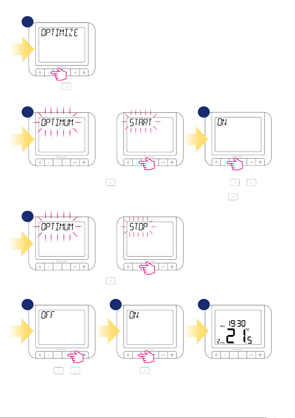
25
The optimization function is an energy-saving algorithm used for efficient control of the
heating device, ensuring better thermal comfort at certain times of the day. When the
OPTIMUM START function is active, the thermostat sends a heating signal to the heat
source beforehand so that the preset temperature in the room is reached at the time
specified in the schedule.
Press
.
25 26
Press .
27
Using or ,
select ON or OFF.
Press to confirm.
When the OPTIMUM STOP function
is active, the thermostat, taking into
account the inertia of the system,
switches off the heat source earlier,
keeping the temperature set in the
schedule.
Press
.
28 29 30
Using
select ON or OFF.
or ,
Press
to confirm.
3
The thermostat will go to
the main screen.
13
Page 14
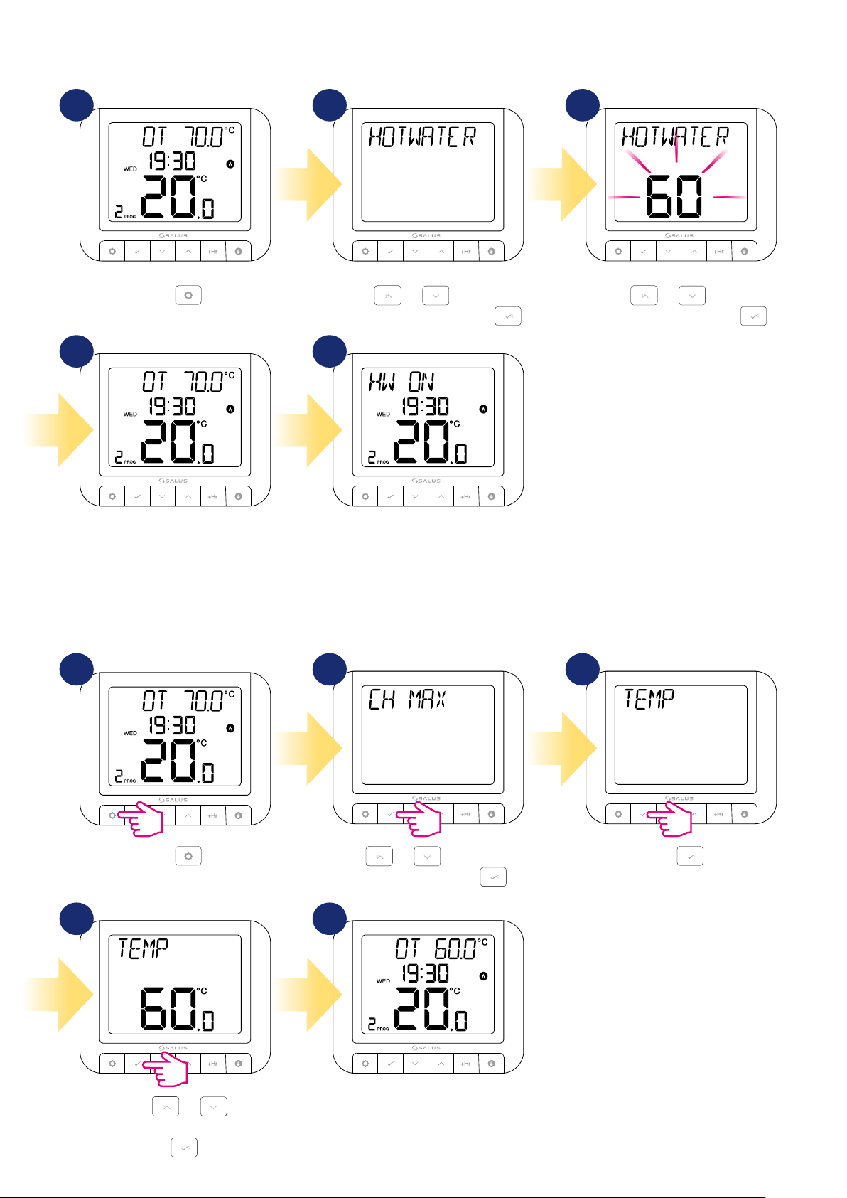
3.4 OpenTherm - Hot Water conguration
RT520 can be congured in Hot Water OPENTHERM system. To congure it follow steps below:
1 2 3
Press .
Using or , navigate to
Hot Water submenu and press .
54
3
The thermostat will return to the
main screen. Press any button.
3.5 Max boiler temperature settings
In this chapter you will learn how to set max temperature for connected boiler. Follow steps below:
1 2 3
The text bar indicates that hot water
is in operation.
Using
temperature and then press .
or , adjust the
14
Press
4 5
Using or ,
set MAX temperature for boiler.
Confirm by button.
.
Using
MAX submenu and press .
or , navigate to CH
3
Thermostat will go back to the main
screen with saving all settings.
Confirm by
button.
Page 15
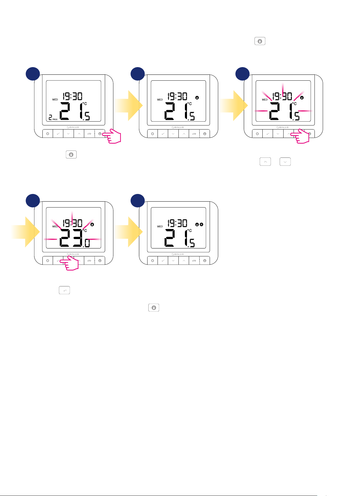
4. User settings
4.1 Manual mode
In manual mode, the thermostat maintains a constant temperature set by the user. To exit mode, press and hold button for 3 seconds. A hand icon
is displayed when manual mode is active.
1
Press button.
4 5
2 3
A hand icon will appear, which means
that thermostat is in manual mode.
To set temperature use
or button.
Confirm your choice using
button.
3
Thermostat will maintain the
temperature until manual change or
manual mode exit (press and hold
button for 3 seconds).
15
Page 16
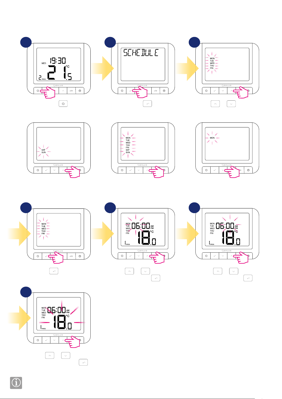
4.2 Schedule mode - programming schedule
In this mode, user can set the schedules for thermostat (temperature setpoints for specic periods of time). Programmed schedules should use all time
periods.
1 2 3
Press
+2 (schedule for the working days
and for the weekend)
.
Press
All (set one schedule for
the entire week)
.
54 6
Using
program type between: 5
Individual (set a daily schedule).
or , select the
16
Press
to confirm.
7
Using
temperature and then press .
Repeat the process for all time periods.
or , set the
3
Using
or , set the hour
and then press .
Using
minutes and then press .
or , set the
Page 17
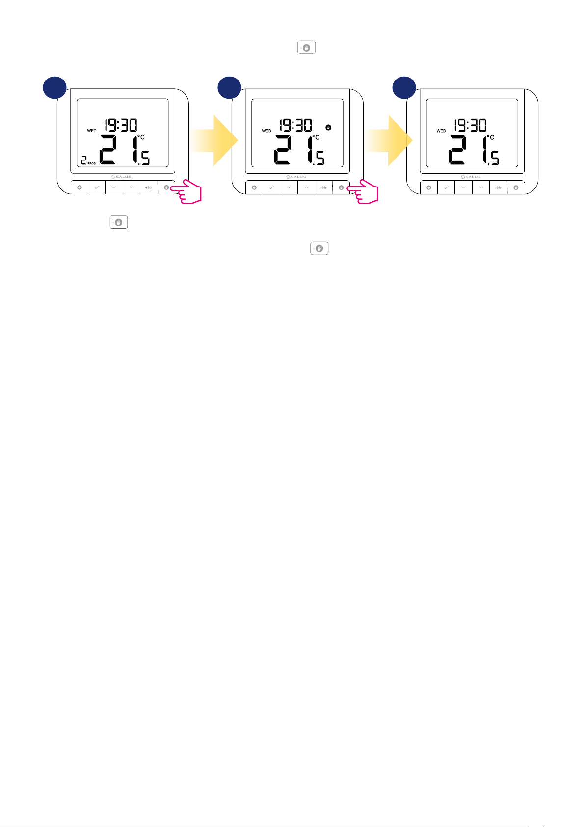
4.3 Switching between manual and schedule mode
In this option, user can switch between manual and schedule mode by using button. To do that please follow steps below:
1 2 3
Press button.
A hand icon will appear, which means
that thermostat is in manual mode.
Now press and hold
button.
3 sec.
3
Thermostat is in the shedule mode
again.
17
Page 18
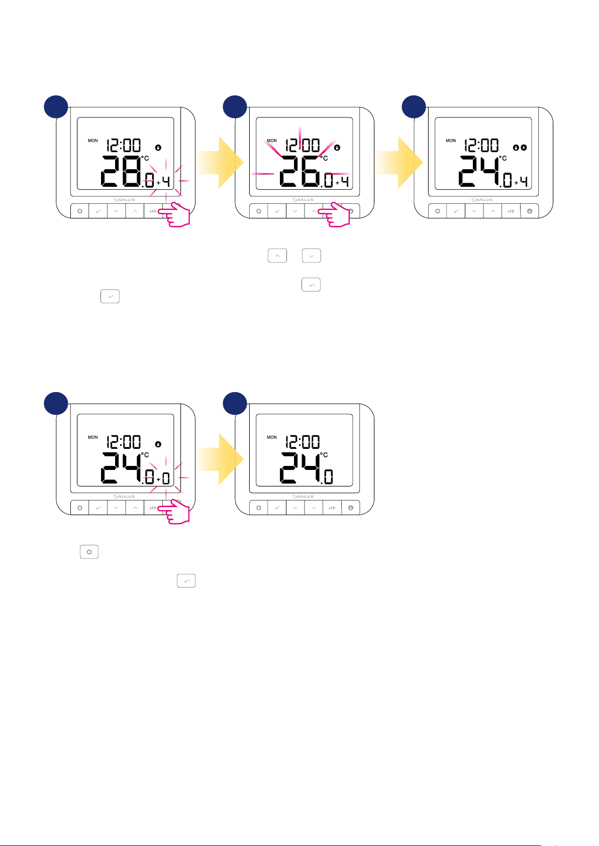
4.4 BOOST mode - hourly temperature override (+Hr)
The function is available in automatic and manual mode. Used to change the temperature to the desired value for a specied number of hours (up to 9
hours). After the elapsed time, the thermostat returns to the previous operating mode.
1
Press +Hr button to set hour for
temporary override (eg. 4 hours = 4
times button pressing). Confirm by
How to stop BOOST mode:
button.
2
Using
the temperature for BOOST mode.
or buttons set
Confirm by button.
3
3
Thermostat is working in BOOST
mode for 4 hours and it will maintain
temperature setpoint for 4 hours.
1
Hold button for 3 seconds or
press +Hr button several times until
“+0” will appear and conrm by
button.
2
3
Thermostat will go back to main
screen and previous work mode.
18
Page 19
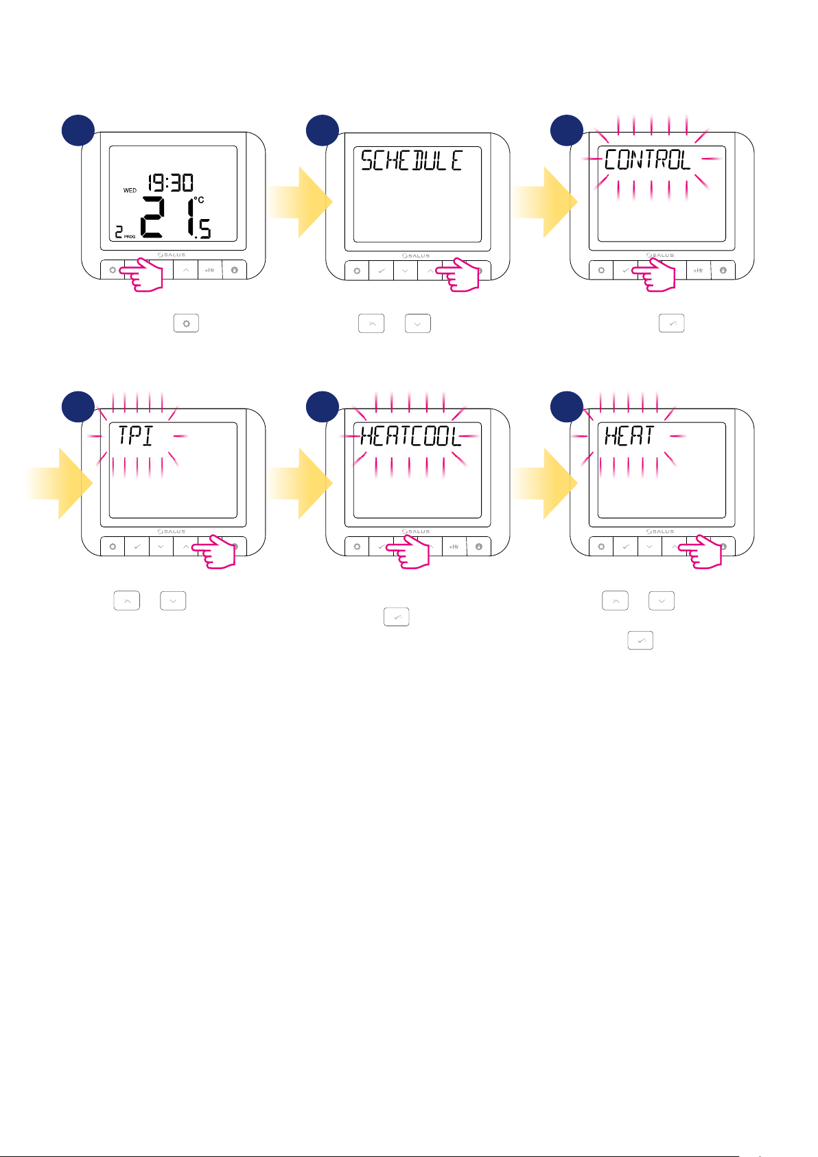
4.5 Control and Heat/Cool settings
In this option user can set control algorithm (TPI, SPAN or Optimize) and set Heat / Cool mode. Please follow the steps below:
1
Press .
4 5 6
2 3
Using
or move between
parameters.
Enter using
button.
Using
or move between
parameters.
Confirm HEAT / COOL option using
button.
3
Using
parameters. Confirm your choice by
or move between
button.
19
Page 20
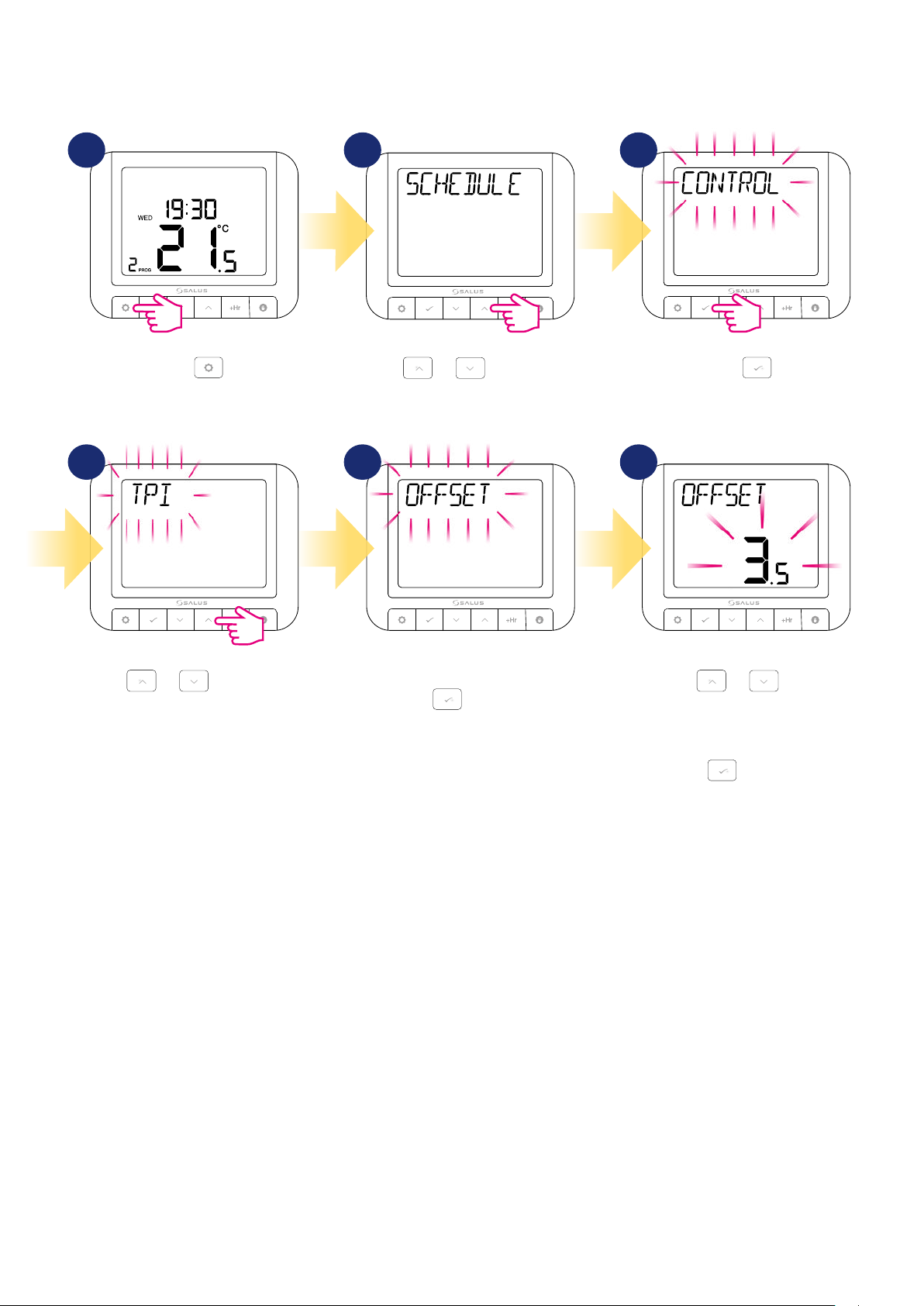
4.6 OFFSET temperature calibration
In this chapter you will learn how to properly calibrate the temperature in the RT520 thermostat. Calibration is possible in the range from -3.5°C to 3.5°C
(in steps of 0.5°C). To calibrate temperature please follow steps below:
1
Press .
4 5
2 3
Using
or move between
parameters.
6
Enter using
button.
Using
or move between
parameters.
Confirm OFFSET option using
button.
3
Using
temperature. Calibration is possible
in the range from -3.5°C to 3.5°C (in
steps of 0.5°C) Confirm your choice by
or calibrate
button.
20
Page 21
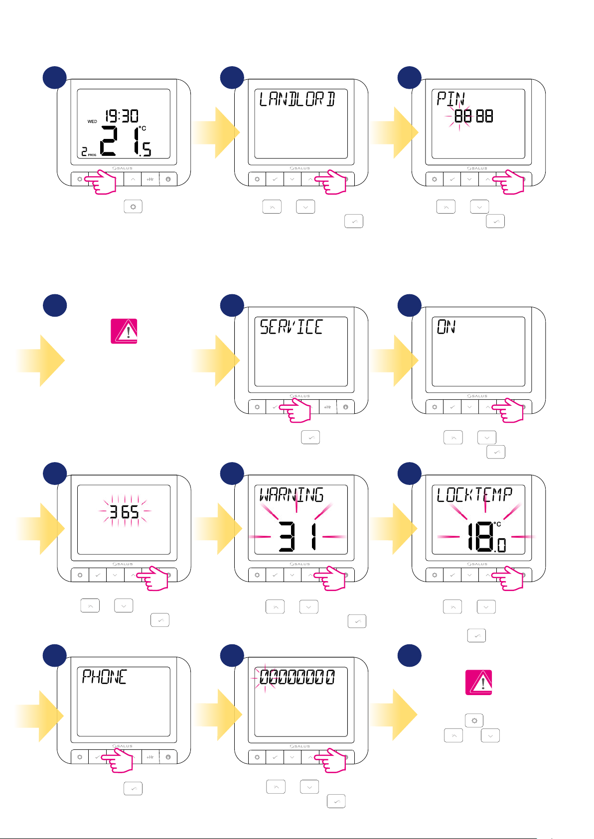
4.7 Landlord settings
Landlord settings is a pin code protected feature that allows the landlord to set a service reminder on the thermostat that will warn the tenant when the
boiler is due its annual service.
1 2 3
Press
Please remember to write
down your pin code so that
you can use the Landlord
menu later without any hassle
from losing it.
7
.
Using
Landlord submenu and press .
or , navigate to
Using or , enter the PIN
code number. Press to confirm
every digit. Note: The first PIN code
entry is also the setting of a NEW PIN
CODE which must be entered each time
to enter the LANDLORD (Admin) menu.
654
Press
.
Using
or , select ON
and press .
8 9
Using
or , select the due
date and then press .
Using
warning period and then press .
or , select the
10 11 12
Press
.
Using or , enter the
phone number. Press to
confirm every digit.
Using
lock temperature and then press
To confirm and exit this
option use
use or buttons
again to move to the next
LANDLORD options (look at
or , select the
.
button. Then
the next steps).
21
Page 22
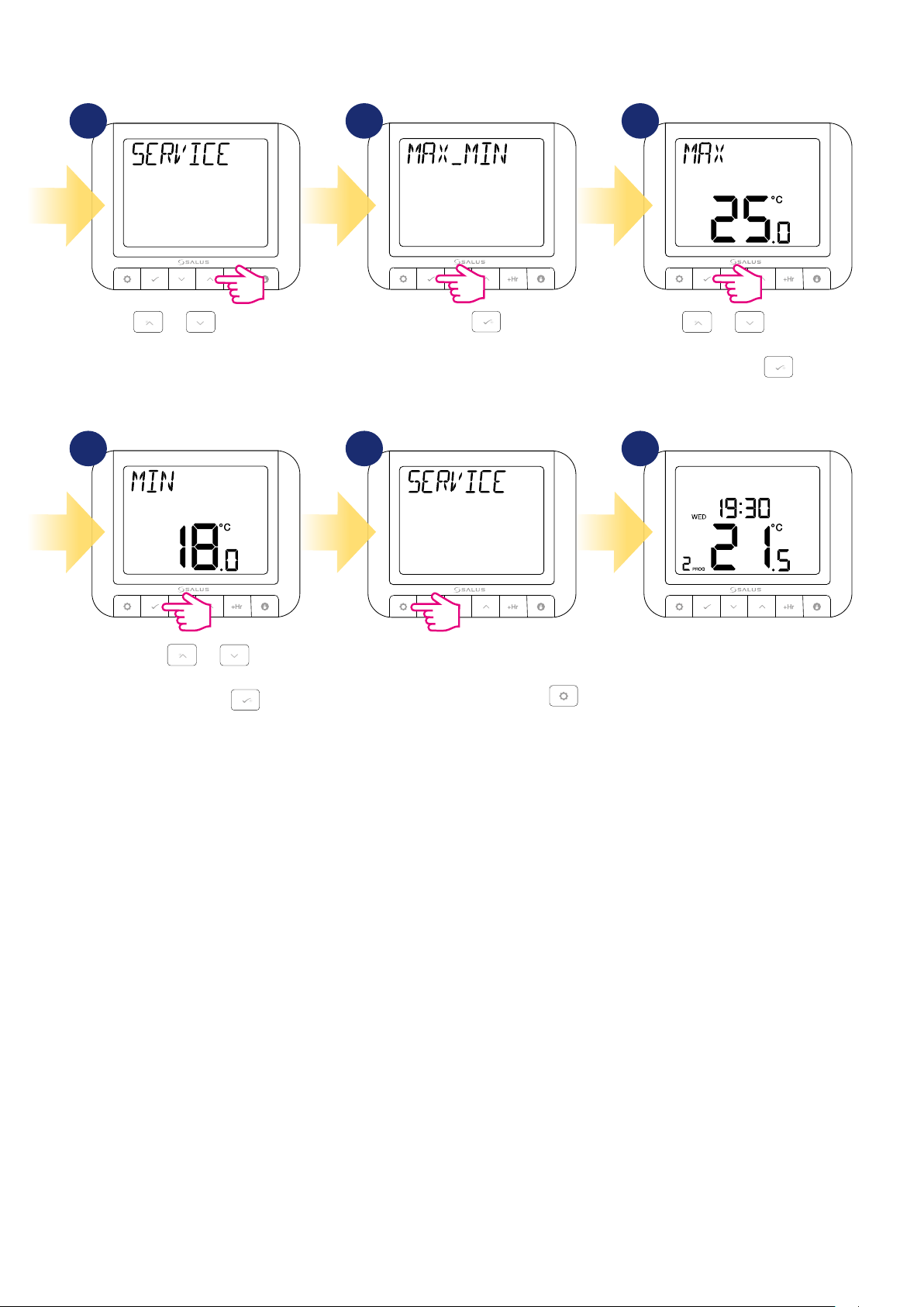
13 15
14
Using or , move to the
next option.
16 17
Now, using
correct MIN temperature setpoint
value. Confirm by .
or , select
Press
Thermostat will go back to SERVICE
option. To go back to the main
screen wait 10 seconds or press
button as long as main screen will be
displayed.
.
Using or , select correct
MAX temperature setpoint value.
Confirm by .
18
3
22
Page 23
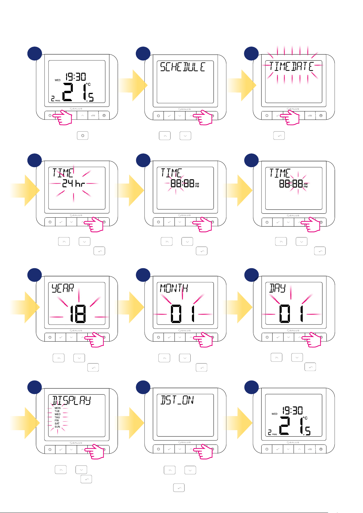
4.8 Time/Date
To set time/date follow steps below:
1 2 3
Press .
Using
or move between
parameters.
4 5 6
Using or , choose
the time format. Press
conrm.
to
Using
and then press
or , set the hour
.
7 8 9
Press
Using
minutes and then press
to enter Time/Date
settings.
or , set the
.
Using
and then press
or , set the year
.
Using
or , set the month
and then press
.
10 11 12
Using
week format. Press
or , select the
to conrm.
Using or , enable or
disable DST (Daylight Saving Time).
Press to conrm.
Using
or , set the day
and then press
.
3
Thermostat will go to the main screen
with saving all the settings.
23
Page 24
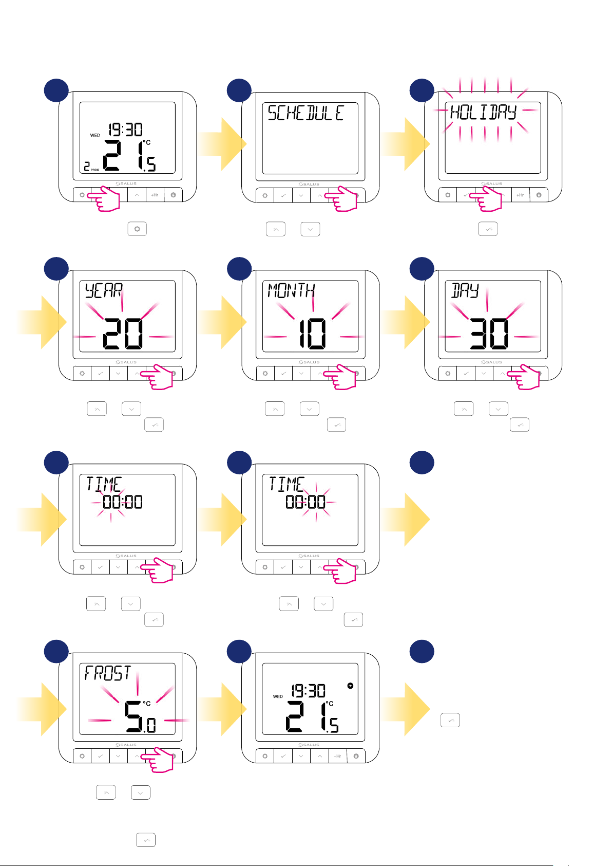
4.9 Holiday mode
Holiday mode is a special program temperature setpoint which thermostat will maintain for specied days. How to set HOLIDAY MODE:
1 2 3
Press .
Using
or move between
parameters.
4 5 6
Using
and then press
or , set the year
.
Using
or , set the month
and then press
.
Press
holiday mode settings.
Using
and then press
to enter
or , set the day
987
Now do the same steps
to set holiday mode’s final day.
.
24
Using
or , set the hour
and then press
Using
.
minutes and then press
or , set the
.
10 11 12
3
Using
temperature which should be
maintaned during holiday mode and
or , set the
then press
.
According to set period of time the
plane icon will appear on the main
screen and thermostat is working in
holiday mode.
To abort holiday mode just
press any button and then
confirm HOLIDAY STOP by
button. Plane icon will
disappear and thermostat will
go back to previous work mode.
Page 25
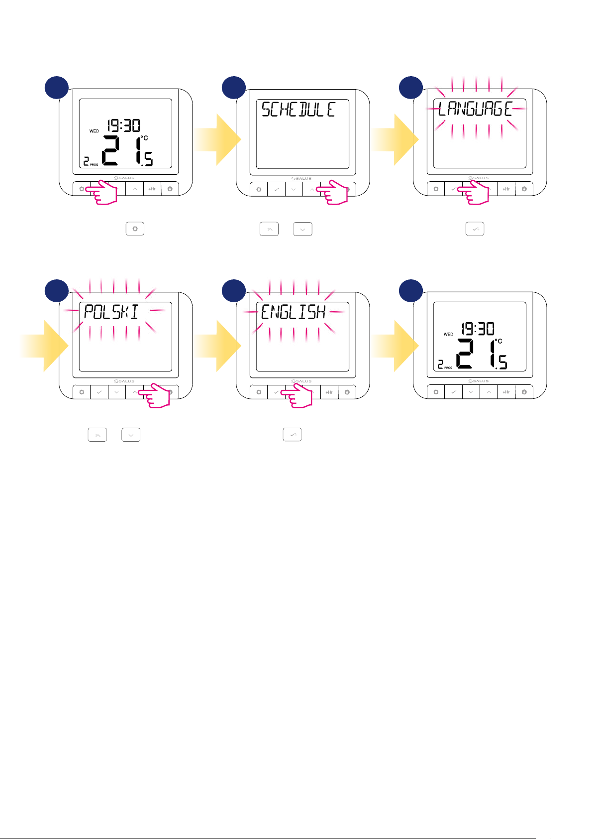
4.10 Language
To choose language follow steps below:
1 2
Press .
4 5 6
Using
or move between
parameters.
3
Press to enter
language settings.
Using
or choose your
language.
Press
to confirm.
3
Thermostat will go to the main
screen with saving the changes.
25
Page 26
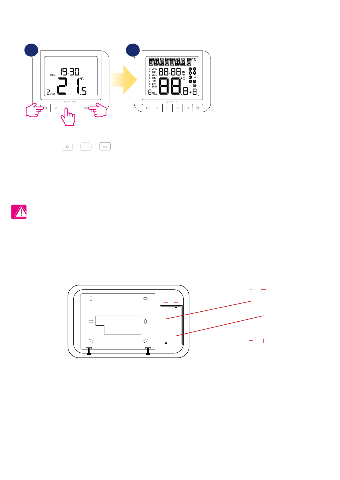
5. Factory Reset
To RESET RT520 thermostat to it’s factory default settings please follow steps below:
1 2
3
To reset the thermostat press and
hold together + +
buttons for 5 seconds.
6. Error codes
Thermostat will display errors only when it’s connected to the boiler by OPENTHERM terminals (A / B). Please refer then to boiler manual. Each
boiler can have dierent error codes.
7. Battery change
Turn the thermostat over so that the back is in front of you. Now look at the picture below:
Thermostat has been reseted.
PLEASE NOTE: User settings will not
be deleted.
26
INSERT THE BATTERIES, PAYING ATTENTION TO THEIR POLARITY!
Page 27
8. Cleaning and Maintenance
The RT520 thermostat requires no special maintenance. Periodically, the outer casing can be wiped clean using a dry cloth (please DO NOT use solvents,
polishes, detergents or abrasive cleaners, as these can damage the thermostat). There are no user serviceable parts within the unit; any servicing or
repairs could only be carried out by Salus Controls or their appointed agents.
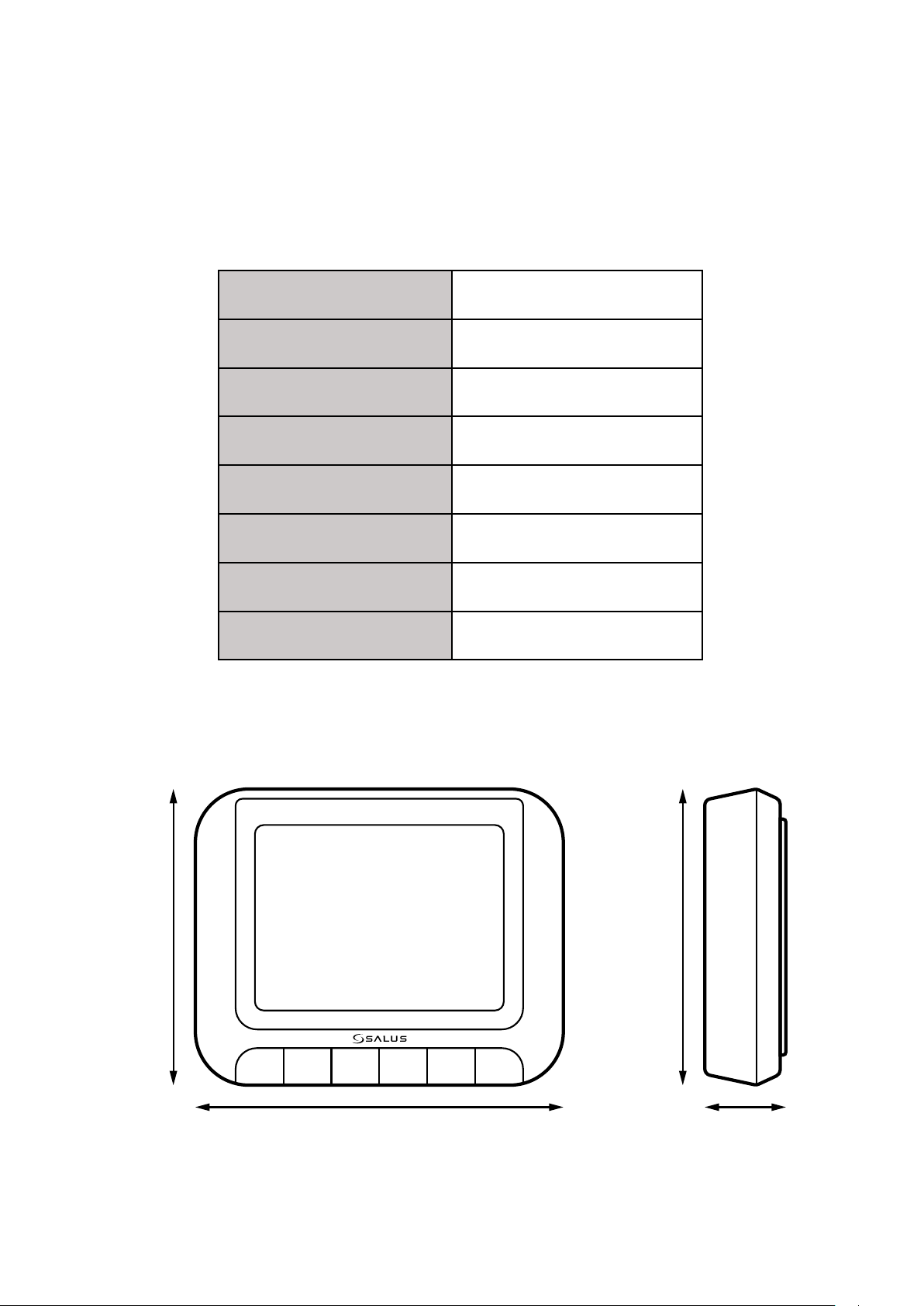
9. Technical Informations
Power supply 2 x AA batteries
Rating max 3 (1) A
Output signal
Temperature range 5 - 33.5°C
Display temperature accuracy 0.1°C or 0.5°C
Control algorithm TPI or Hysteresis: ±0.25°C or ±0.5°C
Communication Wired
Dimension [mm] 95 x 118 x 26
OpenTherm (A / B) or
voltage free relay (NC / COM / NO)
95 mm 95 mm
118 mm 26 mm
27
Page 28
10. Warranty
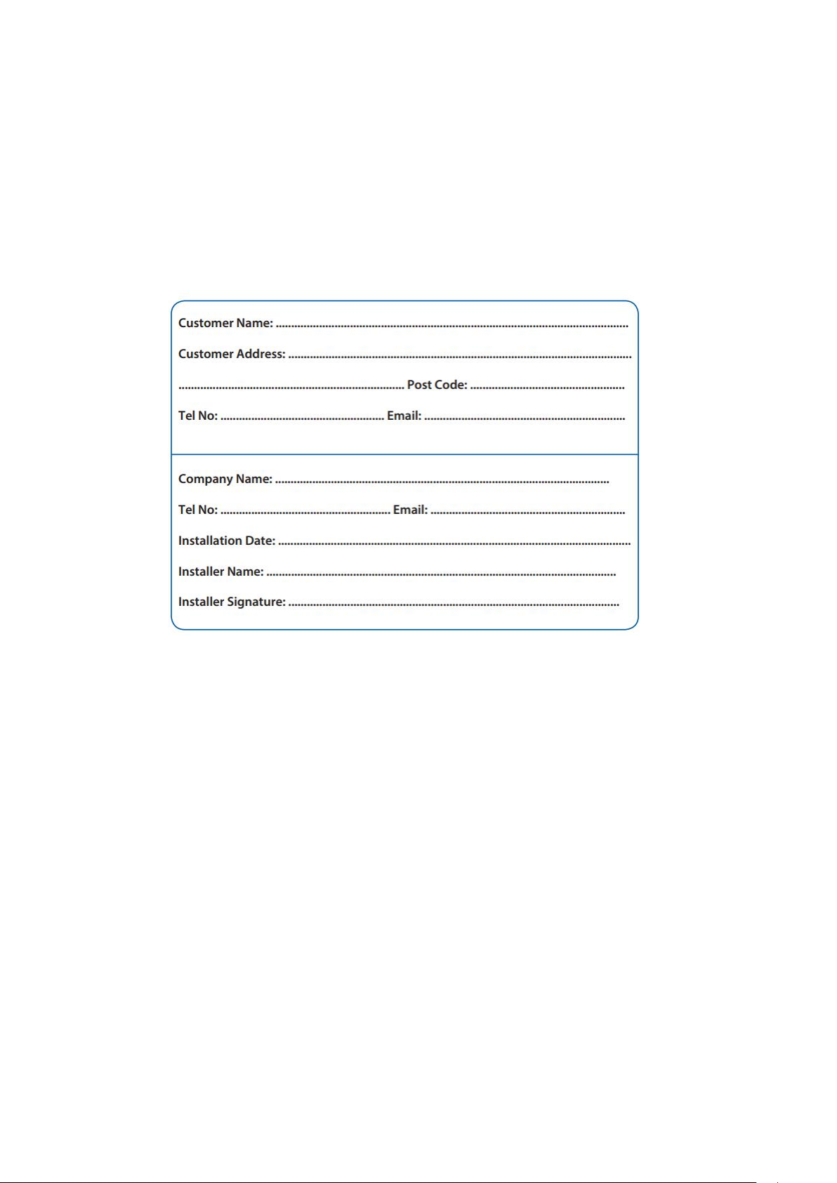
SALUS CONTROLS warrants this product to be free from any defects in material or workmanship and to perform as specied for a period of ve years from
the date of installation. SALUS CONTROLS reserves the sole responsibility for breach of this warranty by repairing or replacing the defective product. This
product includes software that matches the distributor’s identication at the time of sale. The manufacturer / distributor provides a guarantee covering
all functions and specics of the product in accordance with this marking. The distributor’s warranty does not cover the correct operation of the functions
and features available as a result of a product software update.
The full warranty conditions are available at www.salus-controls.eu
28
Page 29

Page 30

IMPORTER:
QL CONTROLS Sp. z o.o. Sp. k.
ul. Rolna 4, 43-262 Kobielice
PRODUCER:
Salus Limited
6/F, Building 20E, Phase 3, Hong Kong Science
Park, 20 Science Park East Avenue, Shatin,
New Territories, Hong Kong
www.salus-controls.eu
SALUS Controls is a member of the Computime Group.
Maintaining a policy of continuous product development SALUS Controls plc reserve the right to change
specification, design and materials of products listed in this brochure without prior notice.
Ver. 5
Issued: 04 V 2021
Soft version: 2.3
30
 Loading...