


T50
 RT5 05RFThermostat Receiver Units
05R
RXST625
RXRT505
RXWBC605
RXVBC605
This instruction manual covers the receivers above
886 MHz

RT505TX |
ST625TX |
0915FLTX
ST325TX
RT305TX
SUPPLIED SEPERATELY

RXRT505
RXST625
RXVBC605
RXWBC605

PRODUCT COMPLIANCE
This product complies with the essential requirements of the following EC Directives:
•Electro-Magnetic Compatibility directive 2004/108/EC
•Low Voltage Directive 2006/95/EEC
•EC Marking directive 93/68/EEC
SAFETY INFORMATION
These instructions are applicable to the Salus Controls model stated on the front cover of this manual only, and must not be used with any other make or model. These instructions are intended to apply in the United Kingdom only, and should be followed along with any other statutory obligations. This accessory must be fitted by a Competent person, and installation must comply with the guidance provided in the current editions of BS7671 (IEE Wiring Regulations) and Part ‘P’ of the Building Regulations. Failure to comply with the requirements of these publications could lead to prosecution. When fitting the receiver always isolate the AC Mains supply before opening or removing the unit from the wall or wall box.
4 |
RECEIVER INSTRUCTION MANUAL |

RT RECEIVER
INTRODUCTION
The RXRT505 is used for the wiring connections and on/off control. The RXRT505 is linked to your thermostat via radio frequency (RF) signal.
Features
•LED status indication
•ON / OFF switch
•868 MHz communication
CONNECTING THE RXRT505 RECEIVER
The RT Receiver should be mounted in a suitable location that is both accessible for the connection of mains and control wiring, and allows good reception of the RF signal. The receiver needs a 230V AC mains supply to operate, and this should be fused appropriately (13A max.). The receiver should be mounted in a location where it will not come into contact with water, moisture or condensation.
The receiver On/Off switch is accessible from the front face of the receiver, as shown in this picture:
RXRT505 INSTRUCTION MANUAL |
5 |
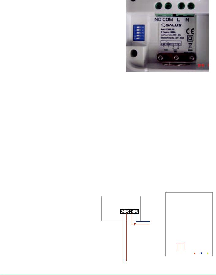
On the front cover of the receiver you will see that there is the On/Off switch and two Light Emitting diodes (LEDs). The switch allows you to turn off the receiver if necessary to prevent it calling for heat. The top LED (red) will illuminate when the switch is in the ‘On’ position and the unit is receiving power. The top LED (green) illuminates when the receiver is receiving a heat call transmission from the
thermostat. The wiring terminals and RF Address Code setting DIP switches are located on the rear of the receiver, as shown above:
RECEIVER WIRING TERMINALS
Terminal |
Identifier |
Description |
1 |
NO |
Normally Open (N/O) Volt free contacts |
2 |
COM |
Common terminal (COM) Volt free contacts |
|
|
|
3 |
L |
Live supply (230V AC) |
|
|
|
4 |
N |
Neutral |
|
|
|
TYPICAL WIRING INSTALLATIONS
The RT receiver is wired the same way no matter if you are wirings 230V or 24V, the receiver will always need a 230V Live and Neutral feed connected into L & N terminals. The COM and NO is to be connected to the boilers external loop (see diagram below), if connected in this way the receiver relay can only switch voltage supplied by the boiler.
BOILER
RECEIVER
N.O. COM L N
N MAINS
L FEED
|
|
Thermostat loop |
|
|
|
|
|
|
|
(Remove link) |
|||||||||
|
|
|
|
|
|
|
|
|
|
Live Feed |
|
|
|
|
|
|
|
||
|
|
|
|
|
|
|
|
|
|
|
|
|
|
|
|
|
|
|
|
|
|
|
|
|
|
|
|
|
|
|
|
L |
|
N |
|
E |
|
||
|
|
|
N |
|
|
L |
|
|
SL |
||||||||||
|
|
|
|
|
|
|
|
|
|
|
|
|
|
|
|
|
|
|
|
|
|
|
|
|
|
|
|
|
|
|
|
|
|
|
|
|
|
|
|
|
|
|
|
|
|
|
|
|
|
|
|
|
|
|
|
|
|
|
|
|
|
|
|
|
|
|
|
|
|
|
|
|
|
|
|
|
|
|
|
|
|
|
|
|
|
|
|
|
|
|
|
|
|
|
|
|
|
|
|
6 |
RXRT505 INSTRUCTION MANUAL |
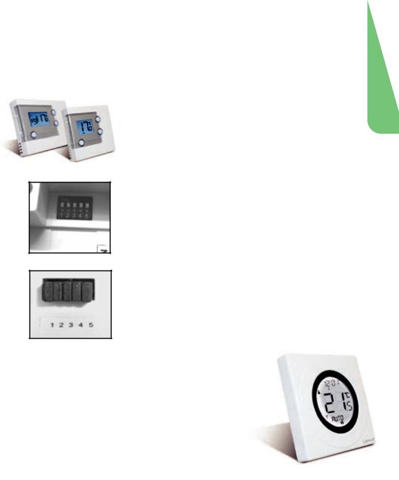
SETTING UP RF COMMUNICATION WITH YOUR THERMOSTAT
RT505TX / RT305TX
Thermostat
DIP Switches
Jumper Caps
After you have switched the receiver on, the thermostat will automatically pair* with the RT505TX and the RT305TX (only). When the red LED stops flashing, the unit has successfully paired.
If you have difficulty in pairing the thermostat, we recommend changing the address codes in the thermostat and the receiver.
To adjust the RF address code of the receiver, simply push up one or more of the 5 DIP switch levers on the DIP switch bank located on the back of the receiver (the levers are numbered 1 to 5 from bottom to top, as shown in the picture left), and then make a note of the setting of each switch:
To adjust the RF address code of the thermostat, remove one or more of the jumper caps located on the back of the unit (labelled 1,2,3,4 and 5, and shown in the picture left) so that the jumper settings match the settings made on the receiver:
ST325TX / ST625TX
1.Switch power on the receiver, the receiver will now automatically enter pairing mode.
2.Enter Pair Menu on the S-Series thermostat and start the pairing procedure*.
3.When the red LED on the receiver stops flashing, pairing has been successful.
* For full instructions on thermostat pairing see:
RT505TX Manual - Page 13 |
ST325TX Manual - Page 15 |
|
RT305TX Manual - Page 9 |
ST625TX Manual - Page 11 |
|
RXRT505 INSTRUCTION MANUAL |
7 |
|

S-SERIES RECEIVERS
INTRODUCTION
The RXST625 is used for the wiring connections and on/off control. The RXST625 is linked to your thermostat via radio frequency (RF) signal.
Features
•LED status indication
•Manual override
•868 MHz communication
CONNECTING THE RXST625 RECEIVER
The RT receiver should be mounted in a suitable location that is both accessible for the connection of mains and control wiring, and allows good reception of the RF signal. The receiver needs a 230V AC mains supply to operate, and this should be fused appropriately (13A max.). The receiver should be mounted in a location where it will not come into contact with water, moisture or condensation.
8 |
RXST625 INSTRUCTION MANUAL |

TYPICAL WIRING INSTALLATIONS
The RXST625 receiver is wired the same way no matter if you are wirings 240V or 24V, the receiver will always need a 240V Live and Neutral feed connected into L & N terminals. The COM and NO is to be connected to the boilers External Loop (see diagram below), if connected in this way the receiver relay can only switch voltage supplied by the boiler.
BOILER
RECEIVER
COM N/O |
|
|
L N |
N MAINS
L FEED
Thermostat loop (Remove link)
|
|
|
|
|
|
Live Feed |
|
|
|
|
||
|
|
|
|
|
|
|
|
|
|
|
|
|
|
|
|
|
|
|
|
L |
|
N |
|
E |
|
|
|
L |
SL |
|
|
|
|
|||||
|
|
|
|
|
|
|
|
|
|
|
|
|
|
|
|
|
|
|
|
|
|
|
|
|
|
|
|
|
|
|
|
|
|
|
|
|
|
|
|
|
|
|
|
|
|
|
|
|
|
|
|
These electrical connections are shown in the table below:
Terminal |
Function |
|||||||
|
|
|
COM |
Common Contact (volt free input) |
||||
|
|
|
NO |
Normally Open Contact (volt free output) |
||||
|
|
|
|
|
|
|
|
Earth Parking (No electrical connection) |
|
|
|
|
|
|
|
|
|
|
|
|
|
|
|
|
|
|
|
|
|
|
|
|
|
|
|
|
|
|
|
|
|
|
|
|
|
|
|
L |
Incoming Mains - Live |
||||
|
|
|
N |
Incoming Mains - Neutral |
||||
SETTING UP RF COMMUNICATION:
Ensure that the slide switches are in AUTO and ON positions and then press the sync button. Press and hold the SYNC button for at least 3 seconds, then release. The receiver will now enter pairing mode, the green LED will now turn red to indicate that the receiver is ready to pair with the thermostat*.
While the signal is being received, the red LED will stay on until the pairing is successful, when pairing is successfull the red LED will turn green.
* For full instructions on thermostat pairing see:
RT505TX Manual - Page 13 |
ST325TX Manual - Page 15 |
|
RT305TX Manual - Page 9 |
ST625TX Manual - Page 11 |
|
|
|
|
RXST625 INSTRUCTION MANUAL |
9 |
|
 Loading...