

Page 1
B220/S220 Parts Counter
Service Instructions
76103-382 Issue 1
*76103-382*
07.09.01
Page 2

Page 3

Table of Contents
Table of Contents
Removing the covers 1
Installing expansion boards 2
Installing a head-up display -3
Status display 4
Error messages 5
Configuring the scale 6
Management mode 6
Restricted service access 6
To enter restricted service access 7
Full service access 7
Verification mode 7
To go to the configuration menus 7
Exiting from full or restricted service access 7
Navigating service mode 8
Product configuration branches 9
Branch 0 - Edit counter 9
Branch 5 - Typical configurations 9
Branch 6 - Weighing functionality 10
Branch 7 - Weighing limits 12
Branch 08 - Gravity compensation 12
Branch 09 - Weight display 13
Branch 19 - Bleeper functions 13
Branch 20 - Power saving 13
Branch 29 - Key press duration 14
Branch 60 - Tares 14
Branch 100 - PLUs 14
Calibration 15
Aborting calibration 16
Replacing a head-up display 17
30kg scales 18
Stiffener plate 18
Base covers 18
Illustrated parts list 19
Head-up display 20
Wiring Diagram 21
B220/S220 Parts Counter Service Instructions i
Page 4

Page 5
Removing the covers
Removing the covers
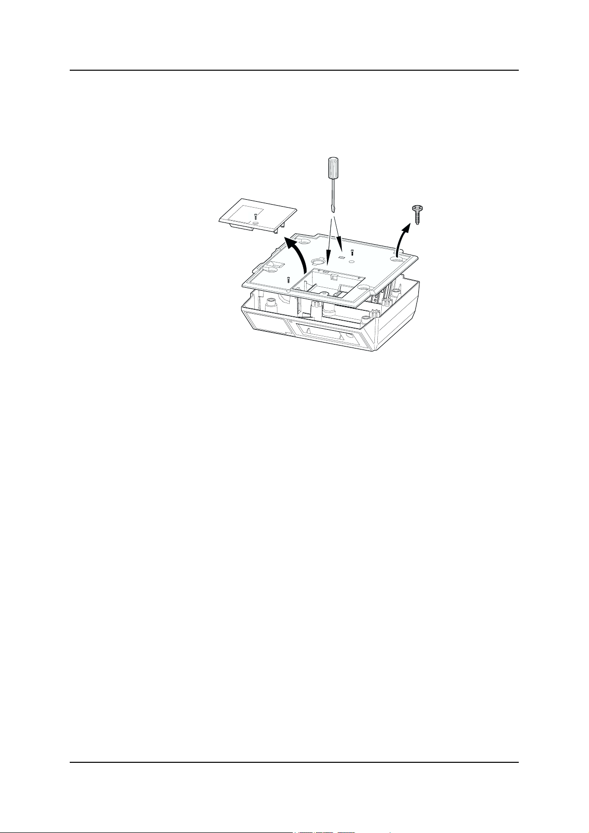
1. Disconnect the power supply from the scale.
2. Remove the weighplate.
3. Break the tamper seal.
4. Remove the screw (A) and remove the expansion board cover.
5. Remove the feet (and the springs if the scale is a 30kg machine).
6. Remove the screw (B) at the front edge of the scale.
7. Lever the clips holding the cover using a flat-bladed screwdriver.
NOTE: When replacing the cover, if either of the clips are damaged an M6 machine
or self-tapping screw (C) can be used to hold the cover in place.
B220/S220 Parts Counter Service Instructions 1
Page 6
Installing expansion boards
Installing expansion boards
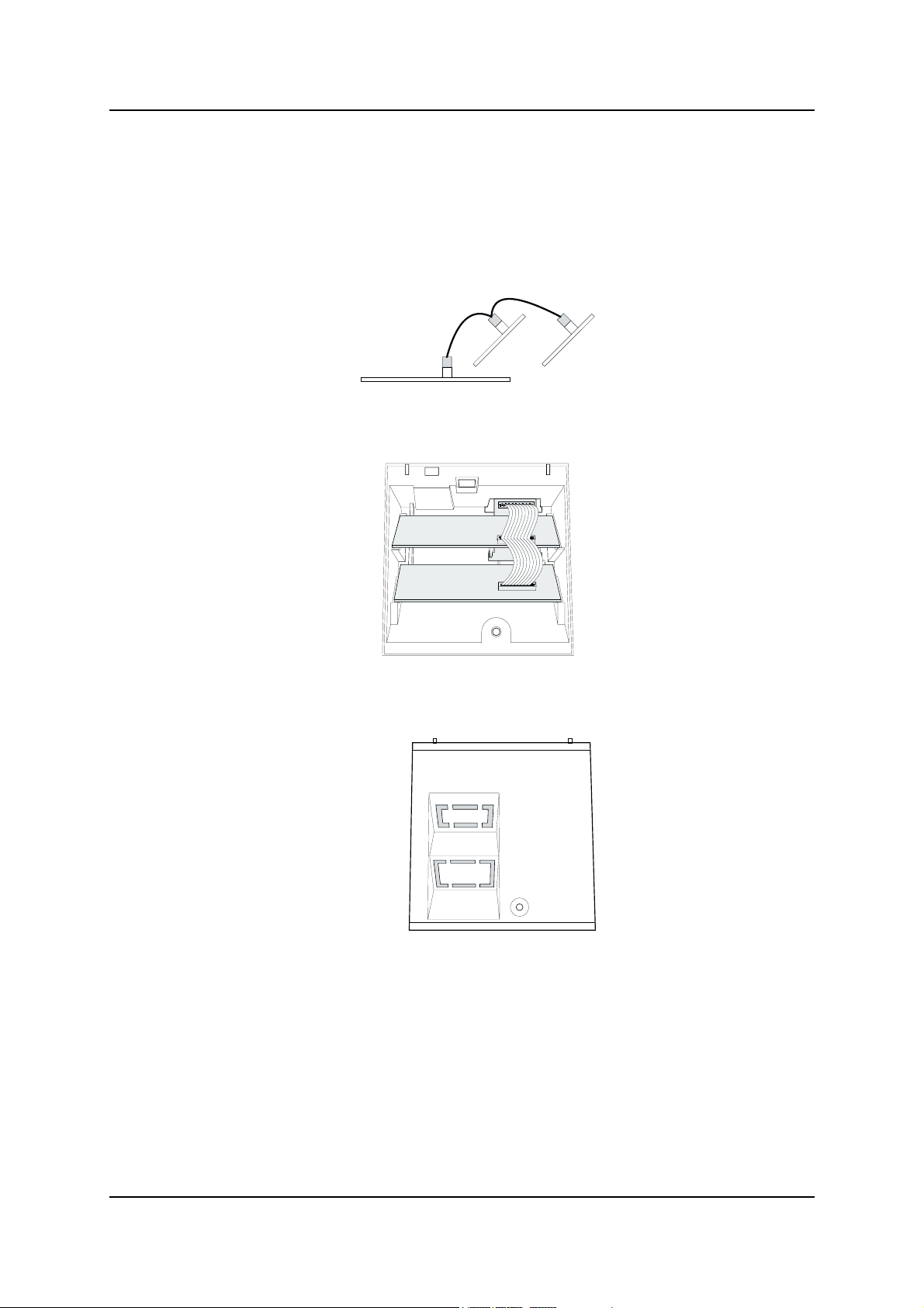
Refer to the fitting instructions included with each expansion board for details on
configuration settings.
1. Connect the wiring loom to the expansion boards.
2. Remove the cover and place the boards in their correct slots.
3. Break off the appropriate blanking plate and replace the cover.
2 B220/S220 Parts Counter Service Instructions
Page 7
Installing a head-up display
Installing a head-up display
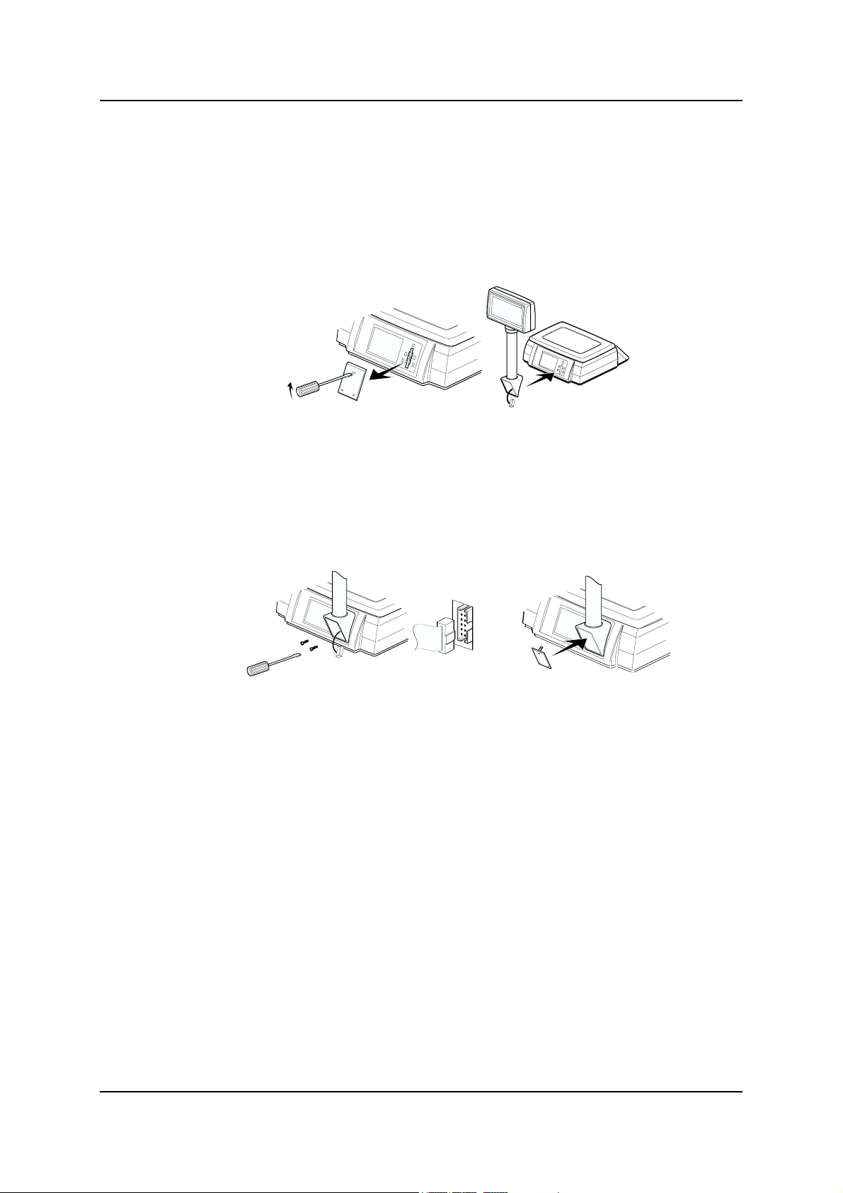
1. Disconnect the scale from the mains power supply, or remove the battery
pack.
2. Using a flat-bladed screwdriver, remove the blanking plate from the back of
the scale.
3. Attach the display using the two slotted screws. Carefully insert the plug from
the display into the socket at the back of the scale.
NOTE: Do not push the connector into the socket too hard as you may damage
the socket.
4. Replace the blanking plate, and reconnect the power supply.
B220/S220 Parts Counter Service Instructions 3
Page 8
Status display
Status display
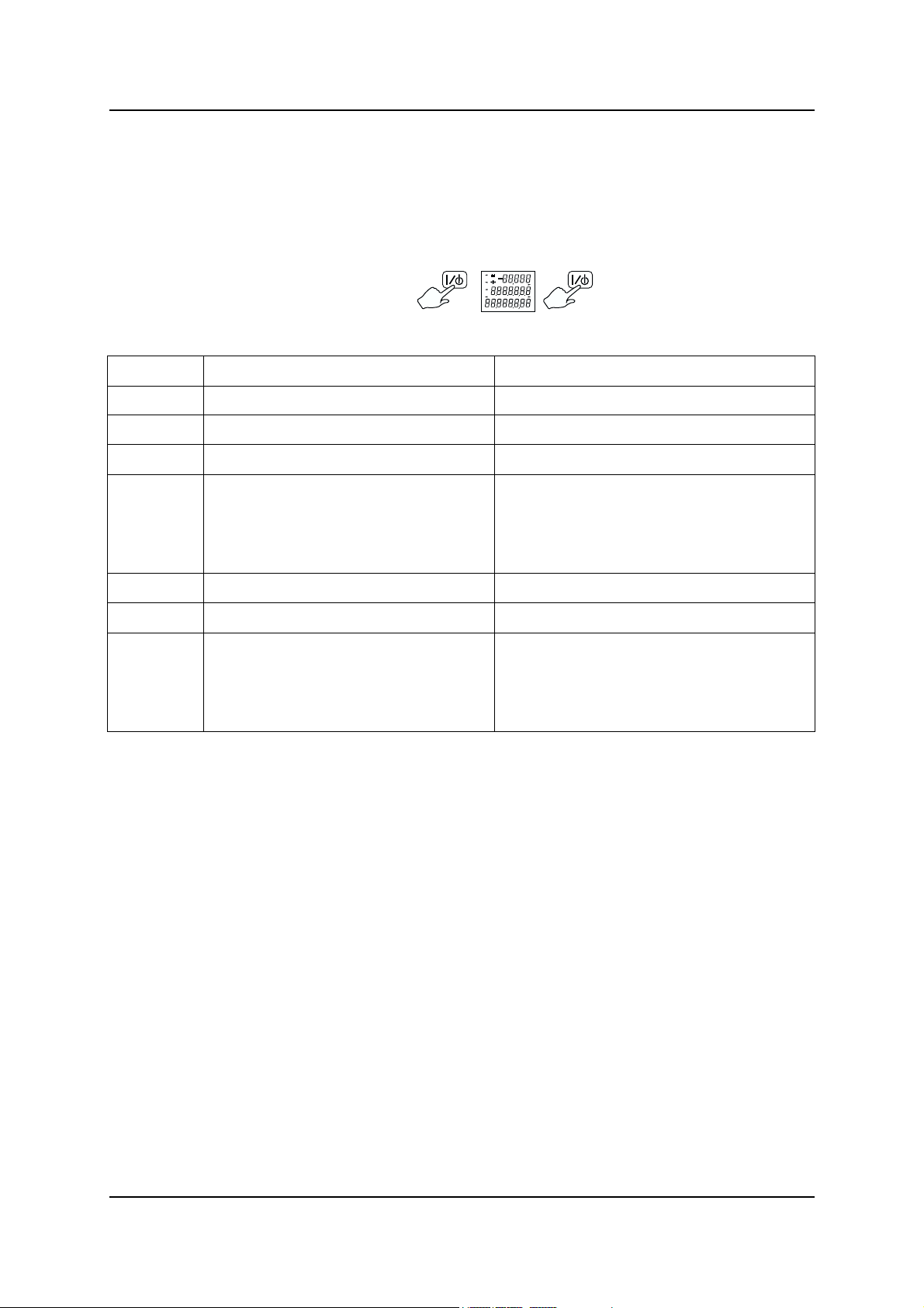
The status display shows some basic information about the scale. to view this
information, press the display test key twice:
Top row Middle row Bottom row
0 Boot block product code Boot block version number
1 Application block product code Application block version number
2 Configuration block product code Configuration block version number
3 Product configuration checksum
status:
0 - OK
1 - Checksum failed
4 Mains/battery voltage Blank
5 Secondary calibration counter Blank
6 Cause of last reset:
0 - Power down
1 - Watchdog
2 - Clock monitor
If you need to contact your authorised service agent for advice, please make a
note of all the settings shown.
Product configuration edit counter
Blank
4 B220/S220 Parts Counter Service Instructions
Page 9

Error messages
Error messages
E5 Disconnect then reconnect the power supply.
E10 Battery failure - replace the batteries (do not use NiCad batteries).
E11 Power supply voltage too high. Make sure the correct power supply is
being used (see page ).
E15 Disconnect then reconnect the power supply.
E19 Software download tool error. Try downloading the application again.
E20 Disconnect then reconnect the power supply, if the error reappears, you
will need to replace the load cell (see page ).
E21 This could be caused by excessive vibration or an incorrect service
calibration. Either adjust the filters (see page ), or re-calibrate the scale
(see page ).
E30 Management/service mode not exited correctly. Re-enter service mode,
select the value to be changed, change the value and go to the next branch
or sub-branch to accept the change.
E35 An invalid configuration for the scale has been given in branch 5, re-enter
the configurations (see page ).
E36 An invalid capacity for the scale has been given in branch 5. Re-enter the
configurations (see page ).
E40 The weight used for user-calibration is unsteady, re-calibrate the scale.
E41 An incorrect weight is being used for user-calibration, use the correct
weights
E42 User calibration is not available for this scale.
E100 Invalid PLU contents, re-program the PLU.
E101 Transaction failed.
E102 PLU write failed. The PLU has been protected in management mode.
E103 Tare failed, re-program the tare.
E110 The counting piece-weight is greater than 10% of the capacity of the scale.
E151 A change to the configuration has failed, reprogram the configuration.
E152 User does not have access to this item (in management mode).
B220/S220 Parts Counter Service Instructions 5
Page 10

Configuring the scale
Configuring the scale
There are three ways to configure the scale:
Management mode
This mode allows the user to configure a few branches of the scale. Because the
configurations can be different for each scale, refer to the User Instructions for
details on the branches available.
To enter management mode:
To exit management mode:
Restricted service access
This will allow you to see all of the scales configuration.
You will not be able to alter the branches that are marked as 'Full service access
only', if you attempt to change these configurations you will see an error message
(E 152).
6 B220/S220 Parts Counter Service Instructions
Page 11

Configuring the scale
To enter restricted service access:
The scale will now be in verification mode (see below).
Full service access
This will give full access to the scales configuration.
1. Unplug the scale from the power supply.
2. Break the security seal and remove the blanking plate.
3. Plug the service tool (part number 18165-140) into the side of the scale.
4. Replace the weighplate and re-connect the power supply. The scale will now
be in verification mode (see below).
Verification mode
Verification mode will display the weight to four decimal places, and zero tracking
will be disabled.
To go to the configuration menus:
If you need to return to verification mode at any time, press:
Exiting from full or restricted service access
To exit:
You will need to disconnect the power supply, (remove the service tool if you are
in full service access) and reconnect the power supply.
NOTE: If you do not exit service mode correctly you will see an E 30 error
message.
B220/S220 Parts Counter Service Instructions 7
Page 12

Navigating service mode
Navigating service mode
Each configuration setting consists of a value and a location, the location consists
of a Branch number and a Sub-branch number.
Function Key
Go to the next branch.
Go to the next sub-branch.
Go to the previous branch. *
Go to the previous sub-branch. *
Go to branch 00.
Select value to be changed.
Change the value.
Note: After changing a value, you must go to the next
branch or sub-branch to accept the change.
Increment the value X10.
Exit service mode.
If you are using the service tool, disconnect the power
supply from the scale and remove the tool before
reconnecting the scale to the power supply.
* This key may not be available on some products.
8 B220/S220 Parts Counter Service Instructions
Page 13

Product configuration branches
Product configuration branches
NOTE: For older application block versions (0-5-0 or earlier) some branches or
sub-branches are not available.
Branch 0 - Edit counter
Sub-branch Value
00 - Default user mode This counter is automatically incremented whenever the product
configuration has been altered.
Branch 5 - Typical configurations
Full service access only.
NOTE: If you enter an incorrect value for these configurations you will see an E 30
or E35 error - re-enter the correct values.
Sub-branch numbers
Capacity 00 01 02 03 04 05 06 07 08 09 10 11 12
6kgx1g 6000 0 0 0 3 1 0 0 0 0 0 0 100
6kgx0.2g 6000 0 0 1 4 1 0 0 0 0 0 0 100
12kgx2g 1200000131000000100
15kgx2g 15000 0 0 1 3 1 0 0 0 0 0 0 100
15kgx0.5g 15000 0 0 2 4 1 0 0 0 0 0 0 100
30kgx1g 3000000031000000100
30kgx5g 3000000231000000100
B220/S220 Parts Counter Service Instructions 9
Page 14

Product configuration branches
Branch 6 - Weighing functionality
Full service access only.
Sub-branch Value
00 - Zero indicator. This determines when the
gross zero indicator appears on the display.
01 - Zero tracking. This is used to account for
minor weight changes over time. For
example, when weighing in dusty
environments.
02 - Balance on power up. When powered up,
the scale determines if it is within its
previous balance range, if it is, it looks at
sub-branch 03. If it is not a balance failed
indicator will appear. A typical example of
an error is if the scale is powered up without
the weighplate on the scale.
03 - Automatic zero self balance. If enabled,
the scale will automatically perform a
balance.
04 - Dual capacity switching. 0 - Allowed for all weight ranges.
0 - Gross zero appears when the range
is between ±0.25 divisions.
1 - Gross zero appears when the range
is between ±0.5 divisions.
0 - Disabled.
1 - Enabled.
0 - Disabled. No test performed.
1 - -5 to 15%.
3 - -2 to 2%.
0 - Disabled.
1 - Enabled.
1 - Only allowed at gross zero.
05 - Weight return to zero. When a weight has
been removed from the scale, this
determines how near to zero the scale must
be before displaying the zero indicator.
06 - Hysteresis. This is used to prevent the
weight display from flickering between the
top of one weight increment and the bottom
of the next.
07 - Normal balance range. This is percentage
of the capacity that the zero can move away
from the power up balance due to zero
tracking, automatic or manual balance.
08 - Filters. If the scale is in an environment
where there is vibration, for example in a
mechanical workshop, filters can be applied
so that the weight display remains steady.
The stronger the filter the longer the display
will take to display a weight.
0 - Gross zero division.
1 - Between 0 and 20 divisions.
0 - Disabled.
1 - Enabled.
0 - 200 Primary capacity (%) multiplied
by 2.
For example, 200 = 100% 50 =
25%.
0 - Default filter (3).
1 -8 1 = Slight filter, 8 = Strong filter.
10 B220/S220 Parts Counter Service Instructions
Page 15

Product configuration branches
Sub-branch Value
09 - Minimum test weight for customer
calibration. Not available.
10 - Maximum correction from customer
calibration. Not available.
11 - Alternate Units. This will convert the
displayed weight into the selected units.
12 - Weight steady. The weight must remain
within the given ± range for a set amount of
time before the weight is displayed.
13 - Tare increment. This sets the tare value
that can be accepted by the scale. For
example, on a 15kg x 5g scale if the tare
increment is set to 1, then the tare weight
must be a multip le of 5g. If the tare weight is
not a multiple, then the scale will not accept
the tare.
0 - 200 Capacity (%) multiplied by 2.
0 - 255 divisions.
0 - Disable alternate units.
1 - USA decimal Pounds.
2 - Grams.
0 - ± 0.1 divisions.
1 - ± 0.25 divisions.
2 - ± 0.5 divisions.
3 - ± 1 divisions.
4 - ± 1.5 divisions.
5 - ± 2 divisions.
6 - ± 3 divisions.
7 - ± 5 divisions.
0 - Allow any tare increment.
1 - Tare increment must be a multiple
of the weight increment.
14 - Automatic re-tare. This sets the percentage
of a tare within which subsequent tares will
also be allowed without having to press the
tare key. This is generally used where there
is minor weight variation between
containers. For example, cardboard boxes.
B220/S220 Parts Counter Service Instructions 11
0 - Disable automatic re-tare.
1- 200 tare range (%) multiplied by 2.
For example, 200 = 100% 50 = 25%
Page 16

Product configuration branches
Branch 7 - Weighing limits
Full service access only.
Sub-branch Value
00 - Minimum weight. This restricts the weight
display so that it remains blank until the
minimum weight has been exceeded.
01 - Under range limit. If the scale is set to
display negative values (Branch 9 subbranch 00) the weight display remains blank
until the negative weight has been
exceeded.
Branch 08 - Gravity compensation
Full service access only.
Sub-branch Value
00 - Calibration gravity factor. This is the
gravity factor of the location where the scale
has been calibrated..
01 - Site gravity factor. This is the gravity factor
of the location where the scale is to be used.
0 - 65535 divisions.
This is the minimum weight (shown on the
overlay) divided by the minimum weight
increment (e).
0 - 65535 divisions.
As published by the support office of your
national distributor.
Minimum value = 975000
Maximum value = 985000
You must enter a six digit value as the
gravity factors are automatically set to five
decimal places.
If the scale is to be calibrated and used in the same gravity zone, then both gravity
factors should be set to 0.
If you intend to calibrate the scale and then send the scale to a different gravity
zone, you must enter the calibration and site gravity factors.
If you do not know the site gravity factor, you must enter the calibration gravity
factor and send a note with the scale stating that the site gravity factor is to be
entered and needs to be re-verified and stamped before being sold to the
customer.
NOTE: Once the calibration and site gravity factors have been entered, the scale
may not weigh correctly until the scale is at the site.
12 B220/S220 Parts Counter Service Instructions
Page 17

Product configuration branches
Branch 09 - Weight display
Full service access only.
Sub-branch Value
00 - Blank net weight display. This sets the
display to either show a negative net weight
or to blank the display when a tare is
created and then removed from the scale.
01 - Weight decimal marker type. 0 - Comma.
Branch 19 - Bleeper functions
Sub-branch Value
00 - Bleep when below zero. 0 - Disabled.
01 - Keyboard bleep. 0 - Disabled.
02 - Target bleep. 0 - Disabled.
03 - Error bleep. 0 - Disabled.
0 - Negative net weight display.
1 - Blank net weight display.
1 - Decimal point.
1 - Enabled.
1 - Enabled.
1 - Enabled.
1 - Enabled.
04 - Bleeper volume. 0 - Quiet.
1 - Loud.
Branch 20 - Power saving
Sub-branch Value
00 - Backlight timeout. This is the length of time
between the last scale activity and the
backlight being activated.
01 - Sleep timeout. This is the length of time
between the last scale activity and the scale
going into 'SLEEP' mode.
0 - Permanently off.1 - 5 seconds.
2 - 1 minute.
3 - 5 minutes.
4 - Permanently on.
0 - No sleep timeout.
1 - 1 minute.
2 - 5 minutes.
3 - 30 minutes.
B220/S220 Parts Counter Service Instructions 13
Page 18

Product configuration branches
Branch 29 - Key press duration
Sub-branch Value
00 - ’Long’ key press duration. 1 - 255 milliseconds X10
(E.g. 200 = 2sec).
Branch 60 - Tares
Sub-branch Value
NOTE: See also, branch 6 sub-branch 13 - tare increment, and branch 6 sub-branch
14 - automatic re-tare.
00 - Manual balance whilst tare active. 0 - Manual balance disabled whilst any
tare is active.
1 - Manual balance clears the tare after
a successful balance.
01 - Minimum piece weight. Weight in grams.
02 - Minimum sample size. Weight in grams.
03 - Item count thousands separator. 0 - Disabled.
1 - Enabled.
04 - Keyboard entered (graduated) tare. 0 - Disabled.
1 - Enabled.
05 - Cumulative tare. 0 - Disabled.
1 - Enabled.
06 - Stored tare. 0 - Disabled.
1 - Enabled.
Branch 100 - PLUs
The branch number for a PLU = 100 plus the PLU number
For example, PLU 5 = 105, PLU 19 = 119
Sub-branch Value
00 - Write protect. 0 - Write enabled.
1 - Write protected.
01 - Piece weight. Weight in grams.
02 - Stored tare. Weight in grams.
14 B220/S220 Parts Counter Service Instructions
Page 19

Calibration
Calibration
You will only be allowed to calibrate the scale when using full service access.
1. Unplug the scale from the power supply.
2. Break the tamper seal, remove the blanking plate and plug the service tool
into the side of the scale.
3. Replace the weighplate and re-connect the power supply.
4. Check that the gravity factors are correct (see page 12).
5. Place a full load on the scale and remove it several times in order to 'exercise
the scale'.
6. Enter calibration mode:
7. Make sure there is no load on the scale.
8. Place a half load on the scale.
9. Place a full load on the scale.
10. Remove half the load.
11. Remove all the load.
B220/S220 Parts Counter Service Instructions 15
Page 20

Calibration
12. The calibration procedure is now complete.
13. Disconnect the scale from the power supply.
14. Remove the service tool from the side of the scale and reconnect the power
Aborting calibration
If you attempt to abandon the calibration procedure you will see:
You must start the calibration procedure again.
supply.
16 B220/S220 Parts Counter Service Instructions
Page 21

Replacing a head-up display
Replacing a head-up display
1. Slide the collar down the column.
2. Gripping the headup display firmly, press hard at the two points marked A,
and break open the covers:
3. Disconnect and remove the damaged display.
4. For the new display, make sure that both dip-switches are in the ON position.
5. Fit the new display, making sure that the loom is connected to socket 'B'.
6. Snap the covers together and re-fit the collar.
B220/S220 Parts Counter Service Instructions 17
Page 22

30kg scales
30kg scales
For 30kg scales, a stiffener plate must be used.
Stiffener plate
Base covers
If you need to replace a damaged base cover, break off all four cut-outs from the
new cover before replacing.
18 B220/S220 Parts Counter Service Instructions
Page 23

Illustrated parts list
Illustrated parts list
B220/S220 Parts Counter Service Instructions 19
Page 24

Illustrated parts list
Head-up display
20 B220/S220 Parts Counter Service Instructions
Page 25

Wiring Diagram
Wiring Diagram
B220/S220 Parts Counter Service Instructions 21
Page 26

Wiring Diagram
Power supplies
COUNTRY P/N NOTE
UK 70682-256 Low current
UK 70682-259 High current
USA 70682-257 Low current
USA 70682-260 High current
Europe 70682-258 Low current
Europe 70682-261 High current
Load cells
COUNTRY P/N NOTE
Blank 70718-623 Blank 15 kg - No software
Blank 70718-385 Blank 30 kg - No software
22 B220/S220 Parts Counter Service Instructions
Page 27

Index
Index
!
30kg scales 18
30kg stiffener plate 18
B
Bleeper functions 13
C
Calibration 15
Configurations 9
Configuring the scale 6
Covers 1
E
Edit counter 9
Error messages 5
Exiting service mode 7
Expansion boards 2
F
Full service access 7
G
Gravity factors 12
H
M
Management mode 6
N
Navigating service mode 8
P
Power saving 13
Power supplies 22
S
Service access 6
Service access Full 7
Service access Restricted 6
Status display 4
T
Tares 11, 14
V
Verification mode 7
W
Weighing functionality 10
Weighing limits 12
Weight display 13
Wiring diagram 21
Head-up display 3, 20
I
Illustrated parts list 19
K
Key press duration 14
L
Load cells 22
B220/S220 Parts Counter Service Instructions i
Page 28

Page 29

Page 30

This document contains a general guide only of the product of the product and shall not form part of any contract unless specifically agreed by Salter Brecknell Weighing
in writing in each case on the Order Acknowledgement. The specification of the products described herein may vary from time to time and may be altered without notice.
PO Box 9533, Smethwick
West Midlands, B66 2TE
Tel UK: 0870 444 6132 Fax UK: 0121 623 6629
Email: sales@salterbrecknell.co.uk Tel Int: +44 (0)121 623 6675 Fax Int: +44 (0)121 623 6629
 Loading...