


USER`S MANUEL
MODEL HKM – 115
IRONWORKER MACHINE
İzmiiir Yolllu 22.km Mümiiin Gencoğlllu Cad. 16285 BURSA / TURKEY
Tell: +90-224-4700158 (6 lliines pbx) |
Fax: +90-224-4700770 |
|
l |
li |
|
Web: www.sahiiinlllermetalll.com Emaiiilll: iiinfo@sahiiinlllermetalll.com
Spare parts & serviiice: serviiice@sahiiinlllermetalll.com

C E D E C L A R A T I O N
We as
ŞAHİNLER METAL MAKİNE END. A.Ş.
İzmir Yolu 22.km
Mümin Gençoğlu Caddesi
Bursa / TÜRKİYE
confirm that the machine
HKM 115
Serial Number |
: |
Production Year |
: |
complies with
EC MACHINES DIRECTIVE 98 / 37 / EC
replllacedwiiith EC-Diiirectiiives 91///368///EWG and
93///44///EWG and 93///68///CEE
EC-LowVollltage 73///23///EWG
EC-NoiiiseLevelllDiiirectiiives86///188///EWG
EC-Diiirectiiives EMV 89///336///EWG
and the machine also harmonized with the standards
DIN EN 60204 Part 1
Name |
: Orhan ŞAHİN |
Position |
: General Director |
BURSA, on |
.............................. |
CONTENTS |
Page |
|
General notes |
1 - 2 |
|
General warranty terms |
3 |
|
Safety and accident prevention instructions |
4 |
|
Transportation |
5 |
|
Setting up the machine |
6 |
|
Adjustment of the shear blade |
7 |
|
View of the delivery side |
8 |
|
Technical properties |
9 |
|
Additional tools |
10 |
|
Five work stations |
11 |
- 12 |
Safety explanations |
13 |
- 15 |
Operation of the machine |
16 |
|
Punching table |
17 |
|
Punching tools |
18 - 19 |
|
Arrangement of the punch tools in general |
20 |
- 21 |
Punch capacity |
22 |
|
Safety precautions of the work stations |
22 |
|
Steel bar and profile cutting installation |
23 |
|
Shearing installation |
24 |
|
Angle cutting installation |
25 - 26 |
|
Grooving, grooving tools and parts |
27 |
- 28 |
Stroke adjustment |
29 |
|
Machine rod and lever readjustment |
30 |
|
Hydraulic system, maintenance, lubrication |
31 |
- 32 |
Hydraulic schema |
33 |
– 34 |
Special accessories |
35 |
|
Optional punch die and blade |
|
|
Blade adjustment and part list
Electrical

GENERAL NOTES
1. Introduction
Thank you for choosing a Şahinler Sheet / Metal Working Machine. We are proud to have you in our long list of satisfied customers all over the world.
This User’s Manual is absolutely for your safety and is essential for the machine to have a long production life. As long as you keep up with our Manual you will be able to run your machine smoothly and safely. Keep in mind that the machine is designed absolutely to perform maximum safety and for efficient working.
In this Manual you can find instructions and information about:
Correct installations of the machine
Description of the functional parts of the machine
Set-up and start-up adjustments
Correct standard and scheduled maintenance
Simple safety regulations and accident prevention.
Therefore, as far as the user’s safety is concerned, in this handbook the possible risks connected with machine operation are pointed out as follows:
Attention: Showing the risks of accident, if instructions are not followed.
Warring: Showing the probable damages to the machine or equipment, if the instructions are not strictly followed.
Note: It gives useful information.
It is certainly necessary that the operator should read and understand all the Attention, War-
ring, Note specified in this Manual before starting with operation of the machine and before any lubrication or maintenance intervention
On all steps of installation, operation and maintenance safety must be your first concern for the protection of yourself, other users and the service of the machine. In case of any failure please first refer to this Manual, and then if a solution cannot be found contact first of all the distributor where you purchased our product. Do not forget to refer to the drawings and the numbers for any spare part needed or to define any problem. Make sure you have the serial number and production year of the machine.
Our technical staff will make their best to help you in the most convenient way.
2. Transport
As soon as you receive the machine, check for any visible transport damages. Should there be any visible damages; report it straight away to the transporter company and of course Şahinler Metal Mak. End. A.Ş. or your supplier.

Remove any protective crates around the machine and read the instructions on related chapters of this Manual carefully to set up the machine. If the machine is damaged while transport, immediately take some photographs for insurance claims.
Take precautions while loading / unloading or moving the machine to avoid any injuries. Refer also to related chapter of this Manual for the best way of handling the machine.
3. Electrical Information
All necessary connection procedure can be found on this Manual. Do not try to connect the machine before reading these procedures and fully understanding the drawings. For any unclear matters get in touch with Şahinler Metal Mak. End. A.Ş. or any of the Şahinler distributors. Have the machine connected by a qualified electric technician. For, as we made clear in the “general conditions of guarantee”, under no circumstances installing mistakes, including electrical connection mistake, can not be covered by guarantee agreement. Always turn off power before making any connections or disconnecting the machine.
4. Maintenance
Your machine is designed and produced to work efficiently and smoothly. To achieve this you should also take care while operating the machine. Regard Maintenance sections to have the longest life from your machine. Try and use original spare parts where necessary and most importantly do not overload the machine or do not make any unauthorized modifications.
5. Safety
Take all precautions possible to avoid any personal injury while using the machine. Keep in mind to protect the third party people around the machine. Refer to safety directives.

GENERAL WARRANTY TERMS
Your machine is covered by manufacturer’s guarantee for a period of 12 months from the date of purchase against manufacture defects. The warranty period does not exceed 18 months from the date of delivery from the manufacturer’s factory.
Warranty covers only manufacture defective parts and / or components that are reported as “defective” by a Sahinler Technician or the Agent Technician and must be reported to Sahinler in writing by fax or email.
The manufacturer is responsible for the supply of free of charge spares only and cannot be held responsible for loss of work.
Shipping and customs fees for the spare part must be paid by the end-user.
If a technician travel is necessary Sahinler will not charge for labor and workmanship costs but the customer must pay traveling and accommodation charges.
A Warranty claim does not relieve the Customer from payment obligations.
The Customer can not ask or demand any reimbursement of damage nor the Customer will have the right to extend or delay payment obligations nor the cancellation of order and the refunding of damages as the guarantee is given for the defective parts of the machine and not for the job.
 Note: All warranty claims must be applied with the Model, Serial Number and the Manufacture Year of the machine.
- 4 -

SAFETY AND ACCIDENT PREVENTION INSTRUCTIONS
General Safety Instructions
Following instructions are meant for the operator of the machine and it is the End-User’s responsibility to make sure the operator reads and understands the following and the User’s Manual for safe operation.
Read the User’s manual before operating the machine.
Always inform electric faults to electric technicians.
Keep your working dress or long hair or necklace etc away from rotating parts.
Make sure you know the position of Emergency Stop Buttons on the machine.
Switch off the machine when NOT working.
Work with necessary safety clothes if necessary (safety shoes, glasses , earplugs etc).
Control the Safety features before working and ensure they are working properly.
See and understand Safety Labels on the machine.
Perform periodic maintenance.
DO NOT overload the machine.
If you see abnormal behavior of the machine, stop the machine and inform your supervisor immediately.
Be careful of other people around the machine during operation.
Never modify electric unit.
Never remove any mechanic or electronic safety features from the machine.
Be extremely careful during transport or re-placement of the machine and follow transport instructions in the manual to safety handle the machine.
Machine Specific Safety Instruction
Safety Features
Position of Emergency Stops.
Position of Safety Labels.
Position of the operator during operation.
Danger zones
We recommend you to use upper listed rules. If you use upper listed rules, we hope you will not take industrial accident. Shows danger zones below the picture and these zones workstation of the machine. You don’t touch into the danger zones
- 4 -

SAFETY AND ACCIDENT PREVENTION INSTRUCTIONS
General Safety Instructions
Following instructions are meant for the operator of the machine and it is the End-User’s responsibility to make sure the operator reads and understands the following and the User’s Manual for safe operation.
Read the User’s manual before operating the machine.
Never touch rotating or moving parts.
Always inform electric faults to electric technicians.
Keep your working dress or long hair or necklace etc away from rotating parts.
Make sure you know the position of Emergency Stop Buttons on the machine.
Switch off the machine when NOT working.
Work with necessary safety clothes if necessary (safety shoes, glasses , earplugs etc).
Control the Safety features before working and ensure they are working properly.
See and understand Safety Labels on the machine.
Perform periodic maintenance.
DO NOT overload the machine.
If you see abnormal behavior of the machine, stop the machine and inform your supervisor immediately.
Be careful of other people around the machine during operation.
Never modify electric unit.
Never remove any mechanic or electronic safety features from the machine.
Be extremely careful during transport or re-placement of the machine and follow transport instructions in the manual to safety handle the machine.
Machine Specific Safety Instruction
Safety Features
Position of Emergency Stops.
Position of Safety Labels.
Position of the operator during operation.
Danger zones
We recommend you to use upper listed rules. If you use upper listed rules, we hope you will not take industrial accident. Shows danger zones below the picture and these zones workstation of the machine. You don’t touch into the danger zones
- 4 -
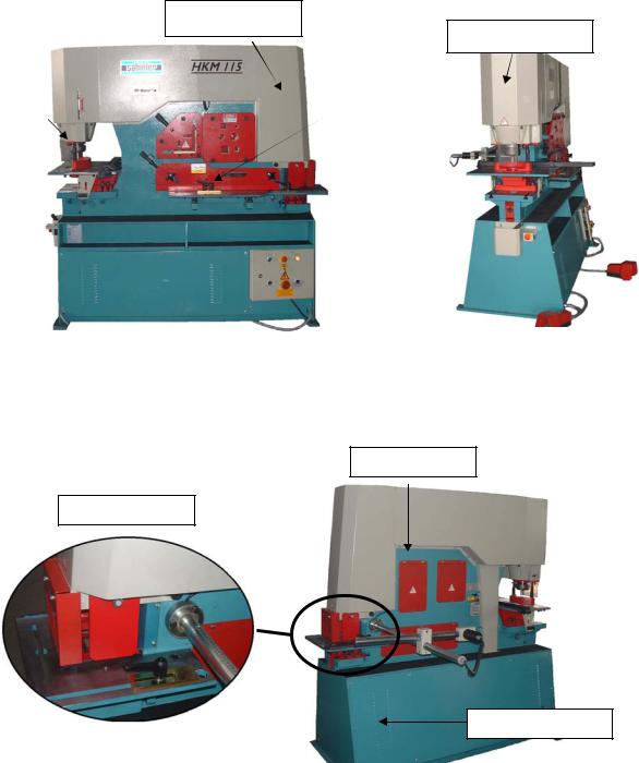
VIEW OF THE DELIVERY SIDE
Shear cylinder
Punch cylinder
Punch Unit |
|
Shear Unit |
|
|
|
VIEW OF THE NOTCHING SIDE
Lever Group
Notching Unit
Hydraulic Unit
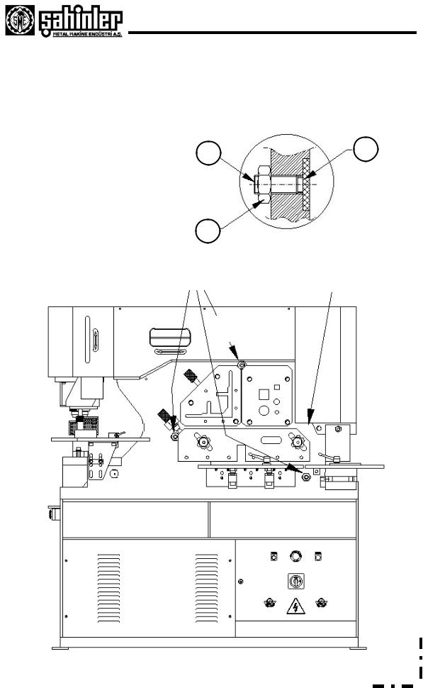
Adjustment of the shear blade
The adjustment of the shear levers should be carried out before any adjustment of the shear blade. The adjustment explain as shown below.
Explanation of figure |
1 |
3 |
|
|
1.Adjustment screw
2.Safety nut
3.Bronze pressure plate
2
Shear lever adjustment |
|
Not to tension |
|
|
|
HKM115
- 3 -
Adjustment of the shear blade
The adjustment of the shear levers should be carried out before any adjustment of the shear blade. The adjustment explain as shown below.
Explanation of figure |
1 |
3 |
|
|
1.Adjustment screw
2.Safety nut
3.Bronze pressure plate
2
Shear lever adjustment |
Not to tension |
|
- 3 -

SETTING UP THE MACHINE
Ask for the help of an experienced and qualified technician while setting up the machine.
1-) Fundamental Plan of the Machine
Four holes (Refer to the drawing below) Dia.15mm
2-) Instructions
For an effective machine, the position and the base of the machine are important. Be careful on these points while placing the machine:
The machine must be placed on a flat, preferably cement base. To fix the machine use bolts. There must be plenty of room all around the machine for easy working.
The machine height is ideal for any workingman.
There must be plenty of Light on top of the machine
855
1830
1870

|
|
|
|
|
|
|
|
|
|
DELİK ZIMBASI |
|
PUNCHING |
|
|
HKM 45 |
HKM 60 |
HKM 65 |
HKM 85 |
HKM 115 |
HPM 65 |
HPM 85 |
|||
|
|
|
|
|
|
|
|
|
|
|
|
|
|
|
|
Ø22x15mm |
Ø28x15mm |
Ø26x20mm |
Ø33x20mm |
Ø34x26mm |
Ø26x20mm |
Ø33x20mm |
||
|
|
|
|
|
|
|
|
|
|
Max. Kalınlıkta çap |
|
Diameter |
x max. thickness |
|||||||||||
|
|
|
|
|
|
|
|
|
|
Çap x kalınlık (Øxt) |
Diameter |
x |
thickness |
Ø38x8mm |
Ø38x11mm |
Ø57x10mm |
Ø55x12mm |
Ø55x16mm |
Ø55x10mm |
Ø55x12mm |
||||
|
|
|
|
|
|
|
|
|
|
Min. Kalınlıkta çap (Özel) (*) |
Diameter |
x min. Thickness Optional) (*) |
Ø100x3mm |
Ø110x3mm |
Ø110x3mm |
Ø110x5mm |
Ø110x5mm |
Ø110x3mm |
Ø110x5mm |
|||||
|
|
|
|
|
|
|
|
|
|
|||||||||||||||
|
|
|
|
|
|
|
|
|
|
|||||||||||||||
|
|
|
|
|
|
|
|
|
|
|
|
|
|
|
|
|
50mm |
55mm |
55mm |
80mm |
80mm |
55mm |
80mm |
|
|
|
|
|
|
|
|
|
|
|
İş kursu |
|
|
|
Stroke |
|
|
|
|||||||
|
|
|
|
|
|
|
|
|
|
Kurs adeti (20mm) |
|
Stroke count in (20mm) |
x 20 |
x26 |
x 25 |
x25 |
x25 |
x25 |
x25 |
|||||
|
|
|
|
|
|
|
|
|
|
|
|
|
|
|
|
175mm |
220mm |
305mm |
355mm |
355mm |
625mm |
625mm |
||
|
|
|
|
|
|
|
|
|
|
Oluk derinliği |
|
|
|
Throat depth |
|
|
||||||||
|
|
|
|
|
|
|
|
|
|
Çalışma yüksekliği |
|
Working height |
940mm |
940mm |
1030mm |
1050mm |
1050mm |
1075mm |
1050mm |
|||||
|
|
|
|
|
|
|
|
|
|
|
|
|
|
|
|
|
|
|
|
|
||||
|
|
|
|
|
|
|
|
|
|
MAKAS |
|
|
|
SHEET METAL SHEAR |
|
|
|
|
|
|
|
|||
|
|
|
|
|
|
|
|
|
|
Düz sac |
|
|
|
Sheet metal |
|
|
200x15mm |
200x20mm |
300x20mm |
380x20mm |
380x25mm |
|
|
|
|
|
|
|
|
|
|
|
|
|
|
|
|
|
|
|
|
||||||||
|
|
|
|
|
|
|
|
|
|
Düz sac |
|
|
|
Sheet metal |
|
|
300x12mm |
300x15mm |
375x15mm |
480x15mm |
600x15mm |
|
|
|
|
|
|
|
|
|
|
|
|
|
|
|
|
|
|
|
|
||||||||
|
|
|
|
|
|
|
|
|
|
Bıçak uzunluğu |
|
|
Blade lenght |
|
|
316mm |
317mm |
380mm |
482mm |
610mm |
|
|
||
|
|
|
|
|
|
|
|
|
|
Açılı Kesim |
|
|
|
Shearing with angle |
80x10mm |
80x10mm |
100x15mm |
120x15mm |
120x15mm |
|
|
|||
|
|
|
|
|
|
|
|
|
|
Çalışma yüksekliği |
|
Working height |
940mm |
940mm |
890mm |
900mm |
900mm |
|
|
|||||
|
|
|
|
|
|
|
|
|
|
PROFİL KESME MAKASI |
ANGLE SHEAR |
|
|
|
|
|
|
|
||||||
|
|
|
|
|
|
|
|
|
|
Dik köşebent (90º) |
|
Angle section (90º) |
100x100x10mm |
120x120x12mm |
130x130x13mm |
150x150x15mm |
150x150x18mm |
|
|
|||||
|
|
|
|
|
|
|
|
|
|
|
|
|
||||||||||||
|
|
|
|
|
|
|
|
|
|
Açılı köşebent (45º) |
|
Angle section (45º) |
70x6mm |
80x8mm |
70x10mm |
80x8mm |
80x10mm |
|
|
|||||
|
|
|
|
|
|
|
|
|
|
Çalışma yüksekliği |
|
Working height |
1140mm |
1140mm |
1130mm |
1155mm |
1160mm |
|
|
|||||
|
|
|
|
|
|
|
|
|
|
|
|
|
|
|
|
|
|
|
||||||
|
|
|
|
|
|
|
|
|
|
DOLU MALZEME MAKASI |
STEEL BAR SHEARING |
|
|
|
|
|
|
|
||||||
|
|
|
|
|
|
|
|
|
|
Yuvarlak / Dörtköşe |
|
Round / Square |
Ø30mm-25mm |
Ø40mm-35mm |
Ø45mm-45mm |
Ø50mm-50mm |
Ø55mm-50mm |
|
|
|||||
|
|
|
|
|
|
|
|
|
|
|
|
|
|
|
|
|
|
|
|
|||||
|
|
|
|
|
|
|
|
|
|
ÇENTİK AÇMA |
|
NOTCHING |
|
|
|
|
|
|
|
|
||||
|
|
|
|
|
|
|
|
|
|
Malzeme kalınlığı |
|
Thickness |
|
|
|
8mm |
10mm |
10mm |
13mm |
13mm |
|
|
||
|
|
|
|
|
|
|
|
|
|
Genişlik |
|
|
|
Width |
|
|
|
35mm |
42mm |
45mm |
52mm |
60mm |
|
|
|
|
|
|
|
|
|
|
|
|
|
|
|
|
|
|
|
|
|||||||
|
|
|
|
|
|
|
|
|
|
Derinlik |
|
|
|
Depth |
|
|
|
75mm |
100mm |
90mm |
100mm |
100mm |
|
|
|
|
|
|
|
|
|
|
|
|
V Derinliği |
|
|
|
V Depth |
|
|
|
60mm |
60mm |
60mm |
70mm |
80mm |
|
|
|
|
|
|
|
|
|
|
|
|
Köşe flanşı |
|
|
|
Angle flange |
|
|
80x8mm |
100x10mm |
100x10mm |
100x13mm |
100x13mm |
100x10mm |
100x10mm |
|
|
|
|
|
|
|
|
|
|
|
Çalışma yüksekliği |
|
Working height |
940mm |
940mm |
890mm |
890mm |
900mm |
|
|
|||||
|
|
|
|
|
|
|
|
|
|
|
|
|
|
|
|
|
|
|
|
|||||
|
|
|
|
|
|
|
|
|
|
ÖZEL KALIPLAR |
|
OPTIONAL TOOLS |
|
|
|
|
|
|
|
|||||
|
|
|
|
|
|
|
|
|
|
|
|
|
|
|
|
|
|
|
|
|||||
|
|
|
|
|
|
|
|
|
|
U - I profil bıçakları |
|
U-I Section blades |
80x45mm |
80x45mm |
130x65mm |
160x90mm |
200x100mm |
|
|
|||||
|
|
|
|
|
|
|
|
|
|
|
|
|
|
|
|
|
|
|
|
|
||||
|
|
|
|
|
|
|
|
|
|
T profil bıçakları |
|
|
T Section blades |
40x6mm |
80x10 |
90x12mm |
100x12mm |
120x12mm |
|
|
||||
|
|
|
|
|
|
|
|
|
|
|
|
|
|
|
|
|
|
|
|
|||||
|
|
|
|
|
|
|
|
|
|
Özel çentik takımı |
|
Special V-notching tooling |
100x100x8mm |
100x100x10mm |
100x100x10mm |
100x100x13mm |
100x100x13mm |
100x100x10mm |
100x100x13mm |
|||||
|
|
|
|
|
|
|
|
|
|
|
|
|
|
|
|
|
|
|
|
|
|
|
||
|
|
|
|
|
|
|
|
|
|
V kıvırma |
|
Lama kıvırma |
V bending |
|
Bar bend. max. |
100x12mm |
150x12mm |
250x15mm |
250x20mm |
250x22mm |
250x15mm |
250x20mm |
||
|
|
|
|
|
|
|
|
|
|
|
|
max. |
Press brake |
|
Capacity |
|||||||||
|
|
|
|
|
|
|
|
|
|
|
|
|
|
|
|
|
|
|
|
|
||||
|
|
|
|
|
|
|
|
|
|
|
|
Sac kıvırma |
|
|
|
Sheet bend. |
|
|
500x3mm |
500x3mm |
700x3mm |
500x3mm |
500x3mm |
|
|
|
|
|
|
|
|
|
|
|
|
|
|
max. |
|
|
|
max.capacity |
|
|
|||||
|
|
|
|
|
|
|
|
|
|
|
|
|
|
|
|
|
|
|
|
|
|
|
||
|
|
|
|
|
|
|
|
|
|
|
|
|
|
|
|
|
|
|
|
|
|
|
|
|
|
|
|
|
|
|
|
|
|
|
Çentik |
|
|
Çene |
Punching on |
|
Bar bend. max. |
85mm |
110mm |
125mm |
125mm |
125mm |
125mm |
125mm |
|
|
|
|
|
|
|
|
|
|
|
kısmında |
|
|
|
|||||||||||
|
|
|
|
|
|
|
|
|
|
|
|
derinliğ |
notcher |
|
Capacity |
|||||||||
|
|
|
|
|
|
|
|
|
|
zımba |
|
|
|
|
|
|
|
|
|
|
||||
|
|
|
|
|
|
|
|
|
|
|
|
|
|
|
|
|
|
|
|
|
|
|
|
|
|
|
|
|
|
|
|
|
|
|
|
|
max. Kapasite |
|
|
|
max capacity |
18x12mm |
20x12mm |
38x8mm |
38x10mm |
38x12mm |
|
|
|
|
|
|
|
|
|
|
|
|
|
|
|
|
|
|
|
|
|
|
|
|
||||
|
|
|
|
|
|
|
|
|
|
TEKNİK ÖZELLİKLER |
TECHNICAL DATA |
|
|
|
|
|
|
|
||||||
|
|
|
|
|
|
|
|
|
|
Motor gücü |
|
|
Motor power |
4kW |
4kW |
5.5kW |
7.5kW |
7.5kW |
5.5kW |
7.5kW |
||||
|
|
|
|
|
|
|
|
|
|
Ağırlık |
|
|
|
Weight |
|
|
|
1300kg |
1250kg |
1600kg |
2430kg |
3100kg |
1900kg |
2900kg |
|
|
|
|
|
|
|
|
|
|
|
|
|
|
|
|
|||||||||
|
|
|
|
|
|
|
|
|
|
|
|
|
|
|
|
|
|
|
|
|
|
|
|
|
|
|
|
|
|
|
|
|
|
|
Makine ölçüleri |
Machine dimensions |
1200x600x1400mm |
1510x590x1570mm |
1625x750x1800mm |
1900x790x1910mm |
1880x790x1990mm |
1450x850x1614mm |
1670x855x1763mm |
||||||
|
|
|
|
|
|
|
|
|
|
|||||||||||||||
|
|
|
|
|
|
|
|
|
|
|
|
|
|
|
|
|
|
|
|
|
||||
|
|
|
|
|
|
|
|
|
|
Basınç |
|
|
|
Power (Pressure) |
45 ton |
60ton |
65ton |
85ton |
115ton |
65ton |
85ton |
|||
7

ADDITIONAL TOOLS
PUNCHING AT THREADING STATION |
|
|
Maximum capacity ( Diameter x Max. thickness ) |
34x26 |
[mm] |
Maximum capacity (Max. diameter x thickness ) |
110x5 |
[mm] |
Throat depth |
355 |
[mm] |
PROFILE CUTTING |
|
|
U – I Section blades |
200x100 |
[mm] |
T Sections blades |
120x12 |
[mm] |
NOTCHING |
|
|
Thickness |
13 |
[mm] |
Width |
60 |
[mm] |
Depth |
100 |
[mm] |
V Depth |
80 |
[mm] |
Working height |
900 |
[mm] |
Special V-notching tooling |
100x100x13 |
[mm] |
Sheet bending max. capacity |
700x3 |
[mm] |
Based on material strength 45 [kg/mm2]
The maximum punching pressure of this machine is 1150 kN ( 115 ton )
The following tools are included in the basic equipment of the machine;
1 C – Spanner 120/130
4,5,6,8,10,14,19 mm. Allen keys
Punch adapter
Punch holder
Stamp and matrix ( 26 mm )
Scraper
Round square blade ( 1 set )
Angle cutting blade ( 1 set )
Profile cutting blade ( 1 set )
Notching tools
- 7 -

FIVE WORK STATIONS
1.1-PUNCHING STATION
All punching operating are processed by means of hydraulic power thus giving the machine the ability to punch very efficiently and silently. It can either be used to punch thick materials or thin materials in layers together. Punching is silent, powerful, efficient. The waste materials in layers together. The punching table consists two parts. First is the punching flange. The second is holder. The holder is a device that holds the material after punching not to come back with the punch. It must be equally adjusted or it can break the punch. There are different holders for different materials. However the standard holder which we supply is suitable for punching is between 6-55 mm.
SAFETY PRECAUTIONS
All power and depth and other adjustment must be done under full control of an experienced technician
Please check all the moving parts before working
Check the punch and die that they are in the same direction
Adjust the holder equally and according to the material
always use the protective plastics
on small and accuracy needing works use special protection
while replacing the punch or die or holder shut the main switch
never leave the machine unattended
do NOT overload the machine
2.SHEARING STATION
The shearing unit has been equipped with a simple and robust fixing installation, which can be adjusted for any material thickness within the cutting the cutting capacity of the machine. A shearing up to 450 for flat bars or the cutting of the flanges of angle profiles, which have previously been cut at inclined-angle cutting stations.
The shearing blades constructed for mass production can be used on both sides ( the upper blade has 2 cutting edges, the lower blade has 4 cutting edges ) and ensure a clean cutting with the minimum deformation, from the full capacity till a material thickness of only 2 mm.
SAFETY PRECAUTIONS
Always use the bolder
Never place any part of your body under the blade
Do NOT overload the machine
3.CUTTING STATION
This station enables the cutting of big angles with a capacity of up to 900 and smaller angles up to 450. The angle between 450and 900 will be obtained, these will be cut first at 900and then at the shearing station of the flange will be cut at the required angle. The fixing installation supports the material in a manner to provide a correct cutting.
SAFETY PRECAUTIONS
Never place your hand or fingers inside the blade.
Do NOT overload the machine
Use holder fitted on this station for a better work

4.PROFILE CUTTING STATION
The machine are equipped as standard with the blades for cutting round and quadrangle bars. Through additional equipment, it is possible to cut at the machine U-section, I-section and T- section profiles in this clearance. The blades are held by simple squeezing jaws which ensure an easy equipment arrangement at the machine without any detailed adjustment.
SAFETY PRECAUTIONS
Never place your hand or fingers inside the blade.
Do NOT overload the machine
Use holder fitted on this station for a better work
5.NOTCHING STATION
The notching station has been equipped as standard with a rectangle unit and threading table having adjustable counter holders, which enable a repeatable positioning. Additional installations are available for narrow widths or V notching of angles up to 450 (V). Furthermore, it is possible to have units for forming at bar ends and for easy notching works.
SAFETY PRECAUTIONS
Never put any part of your body under the blade
Use protective gloves or protective cages for very small works
Do NOT overload the machine
SHOWS OF THE FIVE WORK STATIONS
STANDARD SPECIFICATIONS
Punch and die Ø26
Punch holder
Flange cutting blade
Notching blade
Centralized lubrication
Crescent key
User’s manual
 Loading...