

Page 1
253 329 475-A
Edition of may 2010
Reference Manual
F@ST™ 2804v2
Page 2

Page 3

F@st™ 2804v2 Reference Manual - 253329475-A
Sagemcom document. Reproduction and disclosure prohibited Page 0-1
Sagemcom assiduously monitors technical developments and is constantly seeking to improve
its products in order to let its clients take full advantage of them. It therefore reserves the right to
modify its documentation accordingly without notice.
All brands mentioned in this guide are registered by their respective owners:
- F@st™ is a registered trademark.
- Windows
TM
and Internet Explorer
TM
are registered brands of Microsoft Corporation.
The purpose of this reference manual is to give users the functions for operating and managing
the equipment. The only access level required (Administrator) is protected by a password and
allows one to access these functions in read and write mode for all the user and network
parameters (Login: admin; password: admin).
Configuration of the router by HTTP is described in detail (cf. section 5).
To ease legibility of the reference manual, the term "router" will be used throughout the
document to designate F@st
TM
2804v2 equipment.
Guide to symbols used in this manual
Warns you not to do an action, or commit a serious omission.
Gives you important information which you must take into account
Page 4

F@st™ 2804v2 Reference Manual - 253329475-A
Page 0-2 Sagemcom document. Reproduction and disclosure prohibited
How should the document be used?
This reference manual is organised into sections and annexes. These sections and annexes
cover the following subjects.
Section 1
Presentation of F@st
TM
2804v2 equipment
Section 2
Description of F@st
TM
2804v2 equipment
Section 3
Installation of F@st
TM
2804v2 equipment
Section 4
Configuration of network parameters
Section 5
Configuration of the router by HTTP
Section 6
Description of Internet access service
Section 7
Description of TV over ADSL service
Section 8
Updating the application
Annex A
Troubleshooting
Annex B
CE compliance declaration
Annex C
Environment
Annex D
Technical Characteristics
Annex E
Default configuration
Annex F
Glossary
Annex G
Connection technology
Page 5

F@st™ 2804v2 Reference Manual - 253329475-A
Sagemcom document. Reproduction and disclosure prohibited Page 0-3
Contents
Pages
Guide to symbols used in this manual 0-1
How should the document be used? 0-2
Contents 0-3 to 0-6
List of figures 0-7
1. Introduction 1-1
1.1 Presentation 1-2
1.2 Composition of router pack 1-4
1.3 (Minimum) prerequisites 1-5
2. Description and connection of your router 2-1
2.1 Description 2-2
2.1.1 Connectors 2-3
2.1.2 LEDs 2-4
2.2 Connecting the ports of your router 2-5
2.3 Installing your F@st
TM
2804v2 2-6
2.3.1 Powering up 2-6
2.3.2 Connecting the ADSL cable 2-6
2.3.3 Connecting to your computer 2-8
2.3.3.1 Connecting the Ethernet interface of your router to your computer 2-8
2.3.3.2 Connecting the Wi-Fi interface of your router to your computer 2-9
2.3.4 Connecting the Ethernet interface of your router to your TV decoder 2-10
2.4 Installation instructions 2-11
3. Installing and configuring the F@stTM 2804v2 router 3-1
4. Configuration of network parameters 4-1
5. Information / Configuration 5-1
5.1 Accessing the welcome screen 5-2
5.2 Recommendations 5-4
5.3 ADSL connection status 5-5
5.4 Display frame 5-5
Page 6

F@st™ 2804v2 Reference Manual - 253329475-A
Page 0-4 Sagemcom document. Reproduction and disclosure prohibited
5.5 Status 5-6
5.5.1 Summary 5-6
5.5.2 Diagnostics 5-7
5.6 Internet Connection 5-9
5.7 Wireless 5-10
5.7.1 Basic 5-10
5.7.1.1 Wireless - Basic 5-11
5.7.1.2 Quick Wireless - Security - Configuration 5-12
5.7.2 Security 5-15
5.7.2.1 Network Authentication 5-17
5.7.3 MAC Filter 5-33
5.7.4 Advanced 5-35
5.7.5 Quality of Service 5-39
5.8 NAT 5-42
5.8.1 Port forwarding 5-42
5.8.2 Port Triggering 5-47
5.8.3 DMZ Host 5-50
5.8.4 ALG 5-51
5.9 Advanced Setup 5-52
5.9.1 WAN 5-52
5.9.2 LAN 5-78
5.9.2.1 Advanced 5-80
5.9.3 Security 5-83
5.9.3.1 IP Filtering 5-83
5.9.3.2 Block Sites 5-87
5.9.4 Quality of Service 5-89
5.9.4.1 Queue Config 5-91
5.9.4.2 QoS Classification 5-93
5.9.5 Routing 5-98
5.9.5.1 Default Gateway 5-98
5.9.5.2 Static Route 5-99
5.9.5.3 RIP 5-101
5.9.6 DNS 5-103
5.9.6.1 DNS Server 5-103
5.9.6.2 Dynamic DNS 5-104
5.9.7 DSL 5-107
5.9.8 Port Mapping 5-110
5.9.9 Certificate 5-115
5.9.9.1 Local 5-115
5.9.9.2 Trusted CA 5-118
5.10 Advanced Status 5-120
5.10.1 WAN 5-120
5.10.2 Statistics 5-121
5.10.2.1 LAN 5-121
5.10.2.2 WAN 5-122
5.10.2.3 ATM 5-123
5.10.2.4 ADSL 5-124
5.10.3 Route 5-126
5.10.4 ARP 5-127
5.10.5 DHCP 5-128
5.10.6 Station Info 5-129
Page 7

F@st™ 2804v2 Reference Manual - 253329475-A
Sagemcom document. Reproduction and disclosure prohibited Page 0-5
5.11 Management 5-130
5.11.1 Settings 5-130
5.11.1.1 Backup 5-131
5.11.1.2 Update 5-133
5.11.1.3 Restore Default 5-134
5.11.2 System Log 5-135
5.11.3 SNMP Agent 5-140
5.11.4 TR-069 Client 5-142
5.11.5 Internet Time 5-144
5.11.6 Access Control 5-146
5.11.6.1 Services 5-146
5.11.6.2 IP Address 5-147
5.11.6.3 Passwords 5-149
5.11.7 Update Software 5-150
5.11.8 System Info 5-151
5.11.9 Save/Reboot 5-153
6. Internet access service 6-1
7. TV over ADSL service 7-1
7.1 Introduction 7-2
7.2 Access to the optional TV over ADSL service 7-2
8. Updating the firmware 8-1
A. Annex A - Troubleshooting A-1
A.1 Checking the assignment of an IP address A-2
A.2 Front panel LEDs A-3
A.3 Supervising your router A-4
A.4 "Diagnostics" tool A-5
A.5 Interpreting the LEDs A-7
A.5.1 The "ADSL" LED blinks slowly A-7
A.5.2 "Wi-Fi" LED off A-7
A.5.3 All LEDs are off A-7
A.6 Restarting your router A-8
A.7 Returning to the factory configuration A-8
A.8 Offline mode A-9
B. Annex B - Warnings for safety B-1
B.1 Warnings for safety B-2
B.1.1 Safety levels in relation to the case B-2
B.2 EC compliance declaration B-2
Page 8

F@st™ 2804v2 Reference Manual - 253329475-A
Page 0-6 Sagemcom document. Reproduction and disclosure prohibited
C. Annex C - Environment C-1
C.1 Directive E 2002/96/CE C-2
D. Annex D - Technical Characteristics D-1
D.1 Mechanics; Display D-2
D.2 Characteristics of the different interfaces D-3
D.3 Environmental characteristics D-5
D.4 Application and protocols D-6
E. Annex E - Default configuration E-1
E.1 Default username and password E-2
E.2 Default configuration for the local network (LAN) E-2
E.3 Default configuration for the local wireless network (WLAN) E-3
F. Annex F - Glossary F-1
G. Annex G - Connector Technology G-1
G.1 Pinouts of the " ADSL" connector G-2
G.2 Pinouts of the "PWR" connector G-2
G.3 Pinouts of the "ETH1", "ETH2", "ETH3" and "ETH4" connectors G-3
G.4 Pinouts of the "USB" connector G-4
Page 9

F@st™ 2804v2 Reference Manual - 253329475-A
Sagemcom document. Reproduction and disclosure prohibited Page 0-7
List of figures
Figure 1.1 - Supervising your router.......................................................................................................... 1-2
Figure 2.1 - Overview of case.................................................................................................................... 2-2
Figure 2.2 - Interconnection of ports of F@st
TM
2804v2............................................................................ 2-5
Figure 2.3 - ADSL line / Power Supply Connection................................................................................... 2-7
Page 10

F@st™ 2804v2 Reference Manual - 253329475-A
Page 0-8 Sagemcom document. Reproduction and disclosure prohibited
Page 11

F@st™ 2804v2 Reference Manual - 253329475-A
Sagemcom document. Reproduction and disclosure prohibited Page 1-1
1. Introduction
This section covers ¾ presentation of the F@st™ 2804v2 range § 1.1
¾ composition of the packaging § 1.2
¾ required hardware and software § 1.3
Page 12
1 - Introduction
F@st™ 2804v2 Reference Manual - 253329475-A
Page 1-2 Sagemcom document. Reproduction and disclosure prohibited
1.1 Presentation
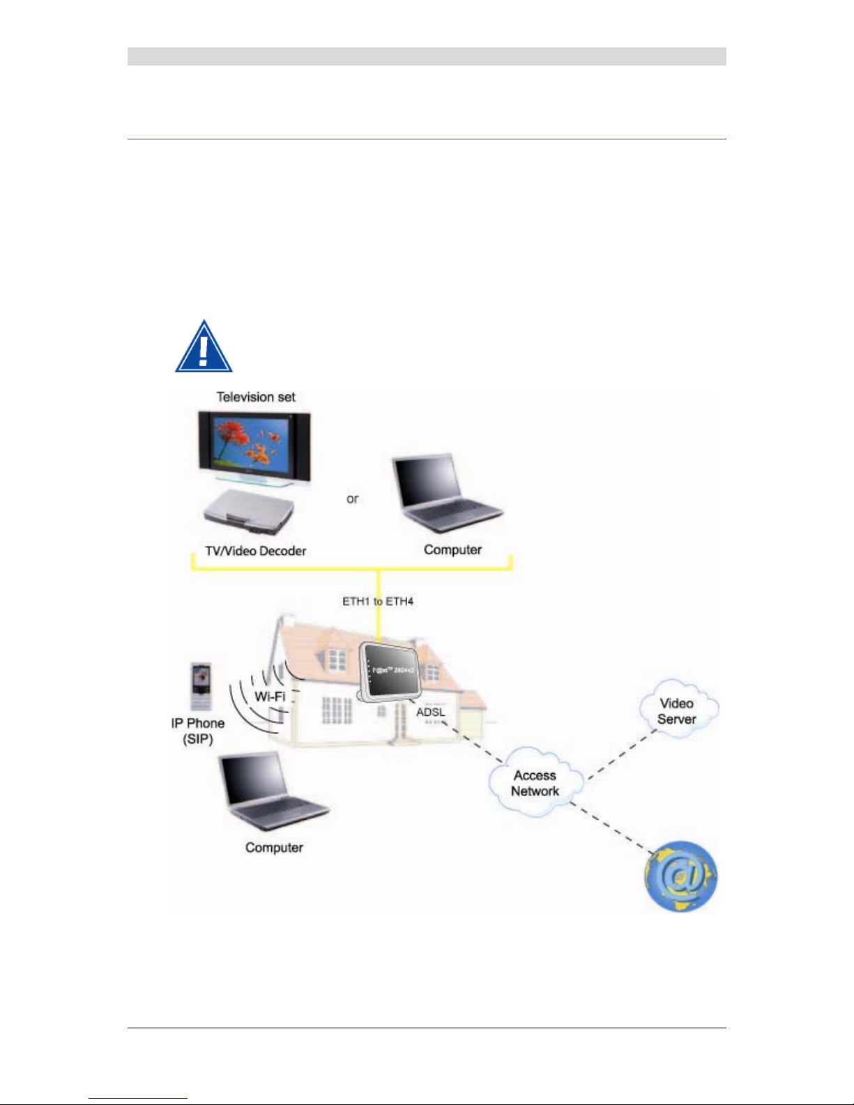
This reference manual is dedicated to the F@st™ 2804v2 product range. These products are
routers which give users, broadband Internet access from their computer or their games
console by various Ethernet (10 or 100 BASE-T) or Wi-Fi (IEEE 802.11b/g/n) interfaces via an
ADSL/ADSL2/ ADSL2+ network.
Using these interfaces, this router enables you both to surf the Internet and to watch television.
It also lets you telephone over the Internet from an IP SIP telephone linked by Wi-Fi to your
router.
F@st™ 2804v2 products adapt the ADSL function for POTS (UIT G.992.1/3/5 Annex A).
Figure 1.1 - Supervising your router
Page 13

1 - Introduction
F@st™ 2804v2 Reference Manual - 253329475-A
Sagemcom document. Reproduction and disclosure prohibited Page 1-3
Its principal characteristics and functions are as follows:
¾ High-performance secure Bridge/Router with ADSL/ADSL2/ADSL2+ interface,
¾ User access:
• 4 x 10/100BT Ethernet ports,
• 1 Wi-Fi port (802.11b/g/n) by mini-PCI,
• 1 USB “Master” port.
¾ DHCP Client/Server/Relay,
¾ DNS Server/ Relay,
¾ Access control (FTP/TELNET/HTTP/SSH Client),
¾ NAT/PAT router - FTP Compatibility, IRC, Net2Phone, Netbios, DNS, Netmeeting, VPN
passthrough (IPSec, IKE, PPTP, L2TP), CUSeeMe, RealAudio, Microsoft IM and others,
¾ Security,
¾ Firewall,
¾ Spanning tree,
¾ Multi-VC ATM and ATM Quality of service (CBR, UBR, VBR),
¾ UpnP,
¾ TR069,
¾ QoS,
¾ Upgrade Firmware (Local and Remote),
¾ Backup/Restore and Upgrade configuration file (Loca l and Remote).
Page 14
1 - Introduction
F@st™ 2804v2 Reference Manual - 253329475-A
Page 1-4 Sagemcom document. Reproduction and disclosure prohibited
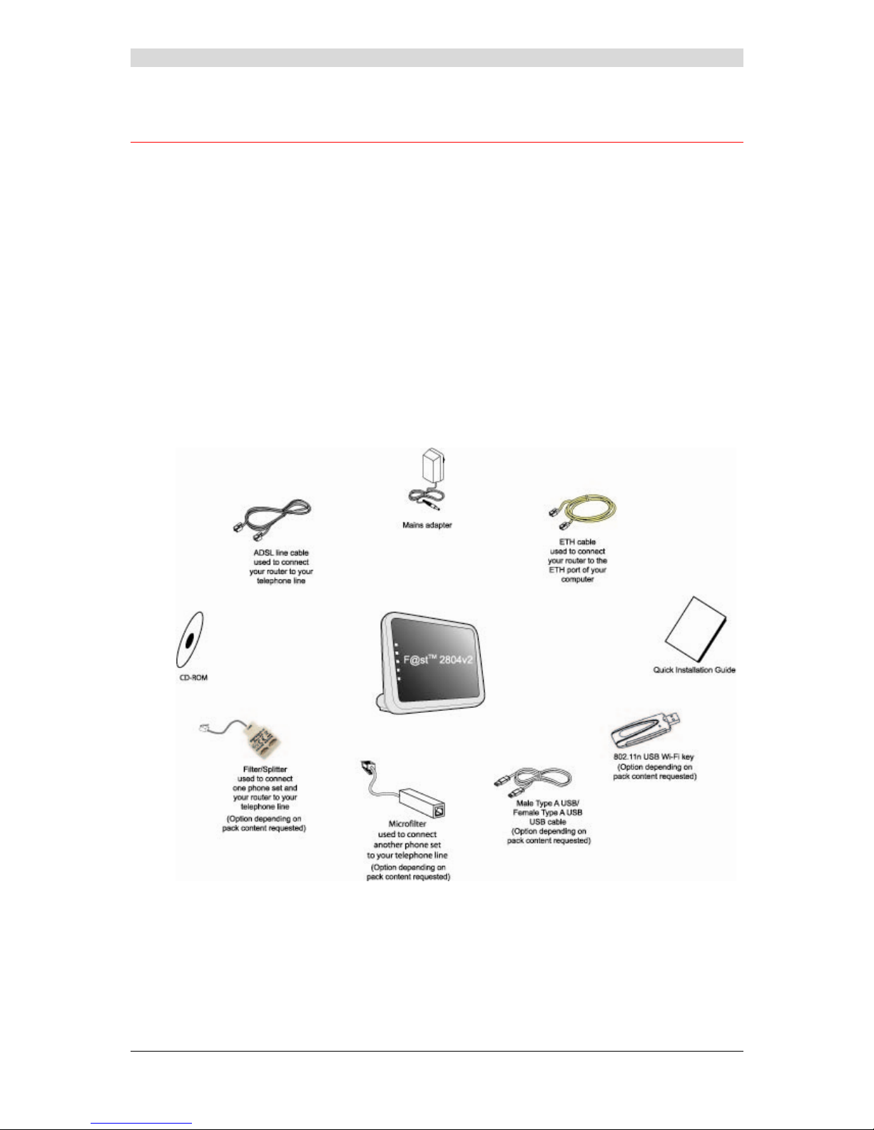
1.2 Composition of router pack
The router is supplied in a pack described below:
¾ 1 F@st™ 2804v2,
¾ 1 mains adapter unit,
¾ 1 Gray ADSL RJ11/RJ11 FDT line cord (length = 3 m),
¾ 1 Yellow Ethernet RJ45/RJ45 linking cord (length = 1.75 m),
¾ 1 Quick Installation Guide,
¾ 1 Installation CD-ROM,
¾ 1 USB Wi-Fi key (optional),
¾ 1 USB Type A male/Type A female cable (length = 1.5 m) (optional),
¾ microfilter(s) (optional),
¾ 1 filter/splitter (optional).
Page 15

1 - Introduction
F@st™ 2804v2 Reference Manual - 253329475-A
Sagemcom document. Reproduction and disclosure prohibited Page 1-5
The CD ROM contains:
• the Reference Manual (F@st™ 2804v2) in PDF format file.
• the CE declaration.
Incomplete or damaged supply. If on its receipt the equipment is damaged or
incomplete, contact your supplier.
1.3 (Minimum) prerequisites
Using a router requires a minimum of:
¾ a computer equipped with:
• a Wi-Fi 802.11b/g/n interface,
or
• an Ethernet interface (10BASE-T or 10/100BASE-T).
¾ a WEB browser (Internet Explorer version 5 or higher recommended).
The minimum configuration of your computer must be:
¾ for Windows: Pentium II, 400 MHz, RAM: 128 MB,
¾ a monitor of minimum resolution: 1024 x 768.
If you wish to use the Wi-Fi function (standard IEEE 802.11b/g/n), you must have the Wi-Fi
Standard pack (see annex G for use of Wi-Fi).
Before installing the router, we advise you to uninstall any modem or other router
(for example, an ADSL router).
Page 16

1 - Introduction
F@st™ 2804v2 Reference Manual - 253329475-A
Page 1-6 Sagemcom document. Reproduction and disclosure prohibited
Page 17

F@st™ 2804v2 Reference Manual - 2533329475-A
Sagemcom document. Reproduction and disclosure prohibited Page 2-1
2. Description and connection
of your router
This section covers ¾ the description of your router § 2.1
¾ connecting the ports of your router § 2.2
¾ installing your router § 2.3
¾ installation instructions § 2.4
Page 18
2 - Description and connection of your router
F@st™ 2804v2 Reference Manual - 2533329475-A
Page 2-2 Sagemcom document. Reproduction and disclosure prohibited
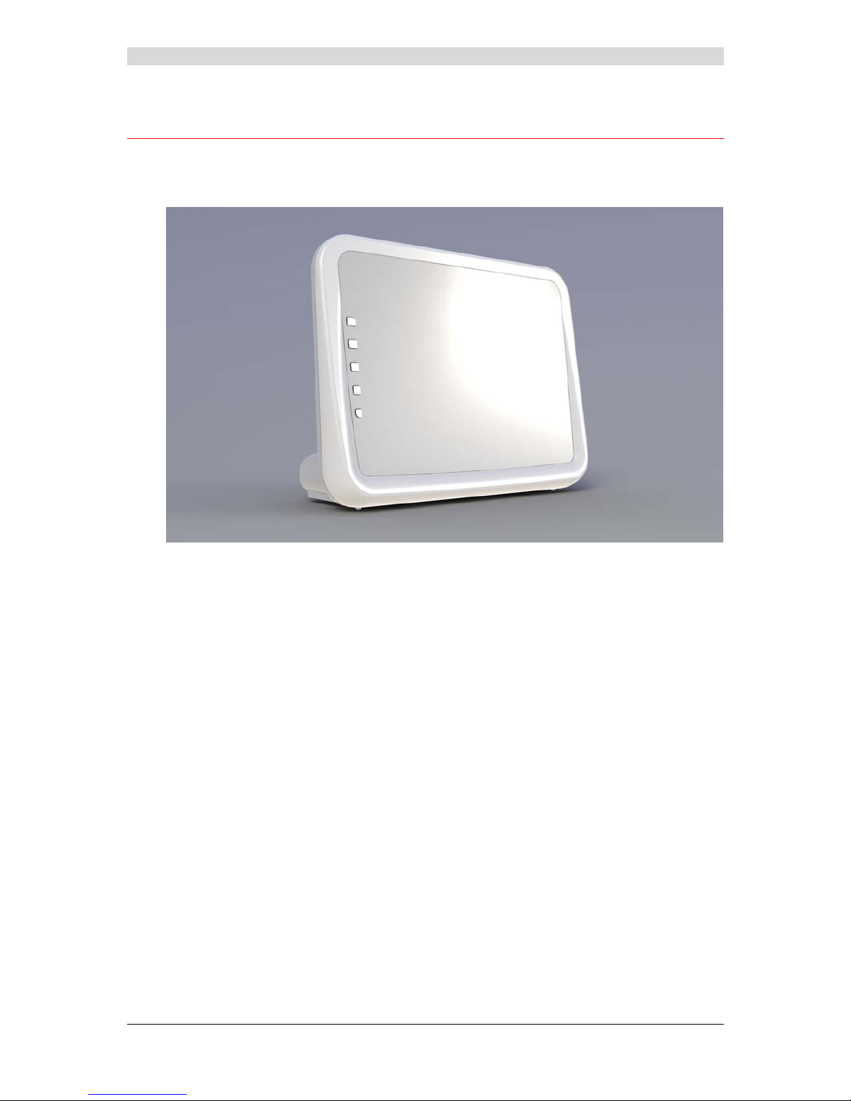
2.1 Description
Figure 2.1 gives an overview of the router (F@stTM 2804v2).
Figure 2.1 - Overview of case
This case consists principally of a lid and a base. Inside is a printed circuit equipped with
electronic components.
The front face of the lid has five display LEDs (see § 2.1.2).
The base has the LED ideograms, manufacturer's logo or the operator' s logo.
Below the base is a label on which the product's identification code, series number and barcode
are shown.
Page 19
2 - Description and connection of your router
F@st™ 2804v2 Reference Manual - 253329475-A
Sagemcom document. Reproduction and disclosure prohibited Page 2-3
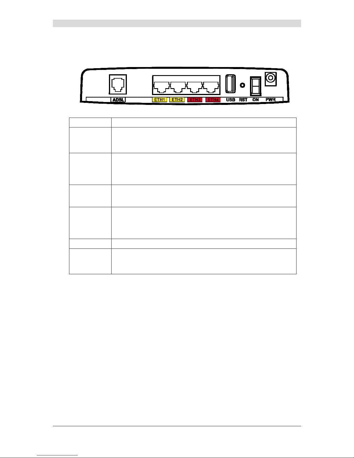
2.1.1 Connectors
Marking Meaning
ADSL
RJ11 connector - 6 pts. This connector is identified by a grey line on the
base (F@st
TM
2804v2).
It is used for the connection to an ADSL line (WAN interface).
ETH1 to ETH4
RJ45 connectors - 8 pts (10/100BASE-T Ethernet Interface). These
connectors are identified by a yellow and a red line on the base.
They are used to connect to a computer or a television set (via a TV/Video
Decoder).
USB
“Master” USB type A female connector (USB Interface) used to “Memory
Sharing” and “Printer Sharing”. This connector is identified by a green line
on the base.
RST
This button allows the router to be reset to the factory configuration
(see § A.7).
Note: It is in shift compare to the other elements, to prevent an
accidental loss of configuration.
ON
On/Off switch.
PWR
Miniature jack fixed connector.
This connector enables the router to be supplied with direct current from a
mains adapter unit.
Page 20
2 - Description and connection of your router
F@st™ 2804v2 Reference Manual - 2533329475-A
Page 2-4 Sagemcom document. Reproduction and disclosure prohibited
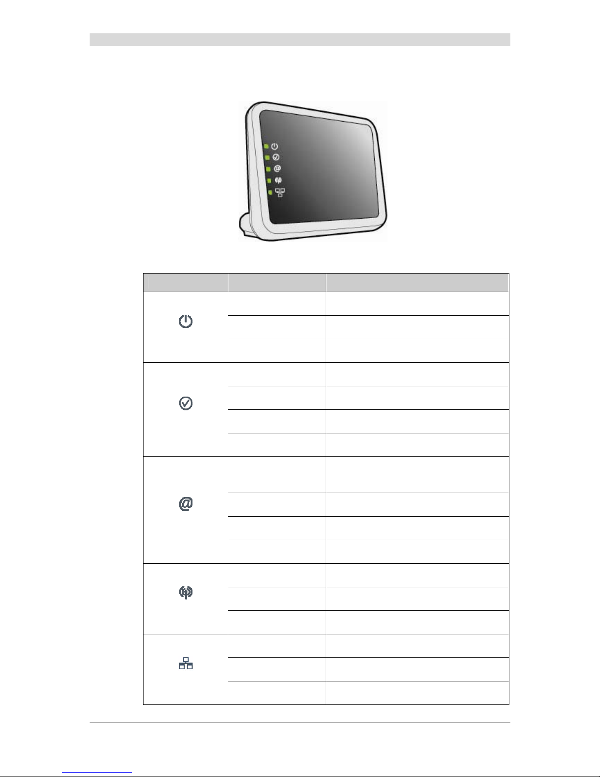
2.1.2 LEDs
The different LEDs of the figure above are described in the following table:
LED Status Meaning
Off
Power Off
Green
Power On - Normal operation
Power
Red
Boot failure - Recovery Mode active
Off
ADSL function off
Green steady
ADSL Showtime
Green blinking Slow
ADSL Line not detected
DSL
Green blinking Fast
ADSL Training in progress
Off
- Power Off
or
- The Internet account must be configured
Green steady
The Internet account is configured
Green blinking
Tx/Rx traffic
Internet
Red
Invalid or unauthorised Internet account
Off
Wi-Fi deactivated
Green steady
WI-Fi activated
WLAN
Green blinking
Wi-Fi Tx/Rx traffic
Off
No link detected on the Ethernet port
Green steady
Ethernet port has detected a link with a device
ETH
Green blinking
Tx/Rx traffic detected on the Ethernet port
Page 21
2 - Description and connection of your router
F@st™ 2804v2 Reference Manual - 253329475-A
Sagemcom document. Reproduction and disclosure prohibited Page 2-5
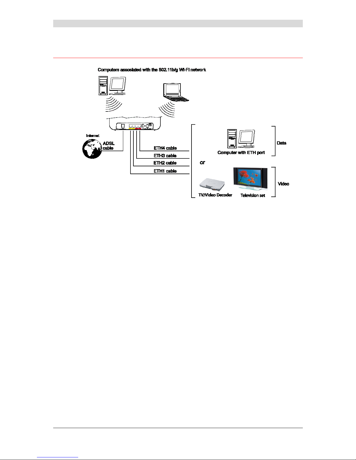
2.2 Connecting the ports of your router
Figure 2.2 - Interconnection of ports of F@st
TM
2804v2
Page 22

2 - Description and connection of your router
F@st™ 2804v2 Reference Manual - 2533329475-A
Page 2-6 Sagemcom document. Reproduction and disclosure prohibited
2.3 Installing your F@stTM 2804v2
2.3.1 Powering up
¾ First connect the end of the mains adapter lead, supplied with the equipment, to the PWR
socket on your Residential Gateway,
¾ Connect the adapter to a nearby power outlet,
¾ Switching on,
¾ The
LED will light up first, followed by the four Ethernet LEDs (1 to 4), then these last
four LEDs will be off. The
and Ethernet (which corresponds to the connected interface)
LEDs should be steady and the
LED blinks during the establishment of the ADSL link,
then steadies like the
LED. The LED should be steady and turn from "Red" to
"Green" when a PPP session has been created.
Note: It lasts around one minute.
2.3.2 Connecting the ADSL cable
¾ Connect one end of the RJ11/RJ11 cable supplied with the equipment to the ADSL socket
of your Residential Gateway.
¾ Connect the other end of this cable as shown in the Figure 2.3.
Page 23
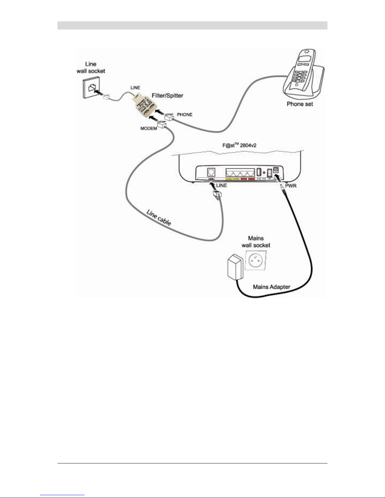
2 - Description and connection of your router
F@st™ 2804v2 Reference Manual - 253329475-A
Sagemcom document. Reproduction and disclosure prohibited Page 2-7
Figure 2.3 - ADSL line / Power Supply Connection
Page 24
2 - Description and connection of your router
F@st™ 2804v2 Reference Manual - 2533329475-A
Page 2-8 Sagemcom document. Reproduction and disclosure prohibited
2.3.3 Connecting to your computer
Two connections may need to be made:
¾ Connection of the Ethernet interface of your router to y our computer.
¾ Connection of the WLAN (Wi-Fi) interface to your computer.
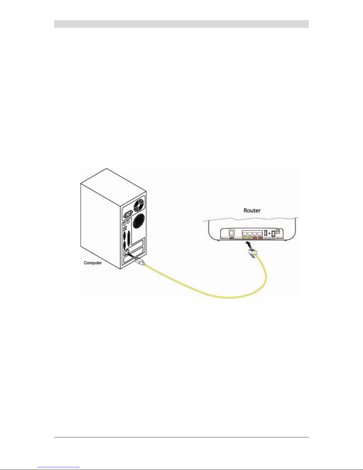
2.3.3.1 Connecting the Ethernet interface of your router to
your computer
¾ Connect the end of the yellow Ethernet cable (RJ45/RJ45) supplied in the pack to the
Ethernet fixed connector (marked ETH1, ETH2, ETH3 or ETH4 in the case of the F@st
TM
2804v2) of your router,
¾ Connect the other end of the cable to your computer.
Page 25

2 - Description and connection of your router
F@st™ 2804v2 Reference Manual - 253329475-A
Sagemcom document. Reproduction and disclosure prohibited Page 2-9
2.3.3.2 Connecting the Wi-Fi interface of your router to
your computer
Wireless linking enables the router to be connected to your computer.
To make this connection you must have a Wi-Fi pack (option). This pack comprises the
following elements:
• 1 Wi-Fi 188470912 key (Dongle) in an anti-static plastic bag,
• 1 USB adapter cord for Dongle,
• 1 CD-ROM.
Inserting a USB Wi-Fi key in your computer
This key should only be connected to your computer during installation of the Wi-Fi drivers
(standard 802.11b/g/n)(see Quick Installation Guide).
You can also use the wifi adapter incorporated in your computer.
Page 26
2 - Description and connection of your router
F@st™ 2804v2 Reference Manual - 2533329475-A
Page 2-10 Sagemcom document. Reproduction and disclosure prohibited
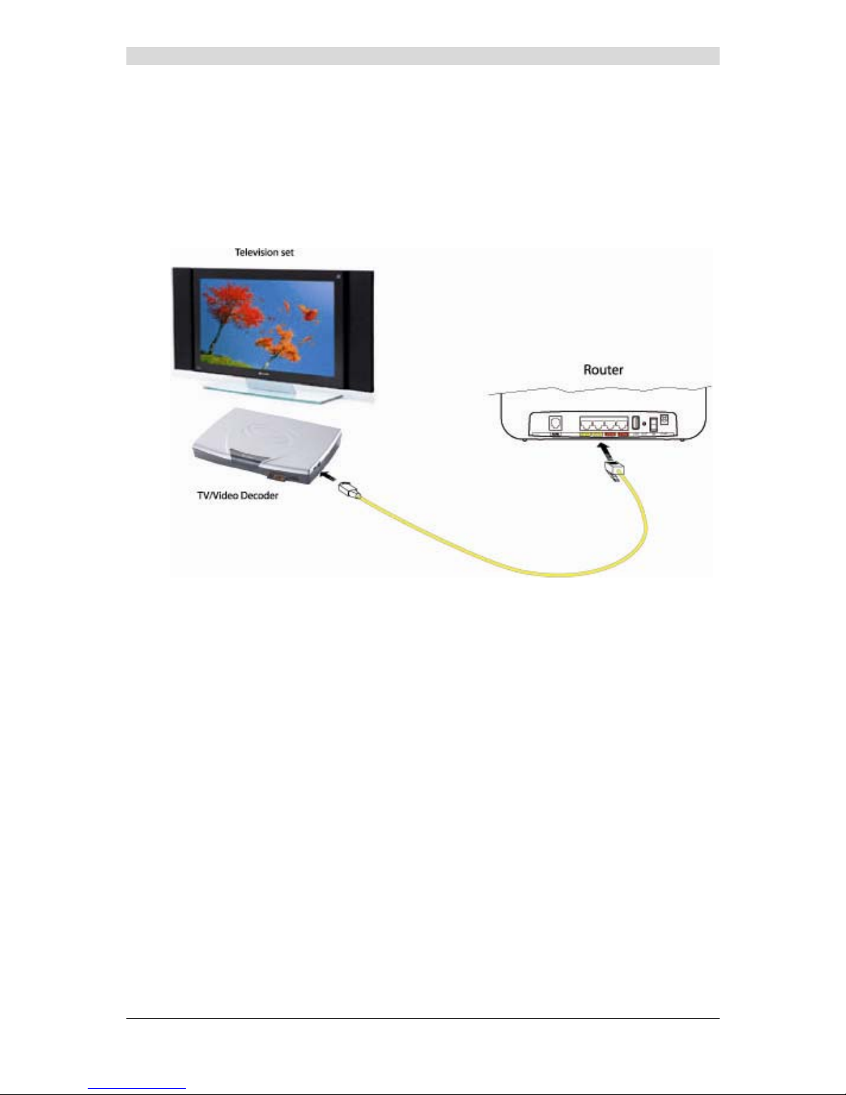
2.3.4 Connecting the Ethernet interface of your router to
your TV decoder
¾ Connect the end of the yellow Ethernet cable (RJ45/RJ45) supplied in the pack to the
Ethernet fixed connector (marked ETH1, ETH2, ETH3 or ETH4) of your router.
¾ Connect the other end of the cable to a TV decoder.
Note: For connection to the decoder, refer to the manufacturer's documentation.
Page 27

2 - Description and connection of your router
F@st™ 2804v2 Reference Manual - 253329475-A
Sagemcom document. Reproduction and disclosure prohibited Page 2-11
2.4 Installation instructions
Environment
¾ The router must be installed and used inside a buildin g.
¾ The ambient temperature must not exceed 45°C.
¾ The router must not be exposed to direct strong sunlight nor to an intense heat source.
¾ The router must not be placed in an environment subject to vapour condensation.
¾ The router must not be exposed to water projections.
¾ The router unit must not be covered.
Power source
¾ Use a network socket with easy access, which is close to the equipment. The power cord is
2 m in length.
¾ Arrange the power cord so as to prevent any accide ntal cutoff of the router.
¾ The router is designed to be connected to a TT or TN type power network.
¾ The router is not designed to be connected to an electrical installation with an IT type
diagram (neutral connected to earth through an impedance).
¾ Protection against short circuits and inter-phase leakages, neutral and earth must be
ensured by the building's electrical installation. The power circuit of this equipment must be
fitted with a 16 A protection against power surges, and with a differential protection.
Maintenance
¾ It is prohibited to open the case. Only qualified personnel approved by your supplier may do
so.
¾ Do not use liquid or spray cleaning agents.
Page 28

2 - Description and connection of your router
F@st™ 2804v2 Reference Manual - 2533329475-A
Page 2-12 Sagemcom document. Reproduction and disclosure prohibited
Page 29

F@st™ 2804v2 Reference Manual - 253329475-A
Sagemcom document. Reproduction and disclosure prohibited Page 3-1
3. Installing and configuring the F@st™ 2804v2
router
Page 30

3 - Installing and configuring the F@st™ 2804v2 router
F@st™ 2804v2 Reference Manual - 253329475-A
Page 3-2 Sagemcom document. Reproduction and disclosure prohibited
For the installation of the F@st™ 2804v2,
please refer to the Quick Installation Guide of this product
Page 31

F@st™ 2804v2 Reference Manual - 253329475-A
Sagemcom document. Reproduction and disclosure prohibited Page 4-1
4. Configuration of network parameters
This section covers ¾ configuring as a DHCP client Page 4-3
¾ reading status of the DHCP server Page 4-4
¾ reading data of the DHCP client Page 4-5
Page 32

4 - Configuration of network parameters
F@st™ 2804v2 Reference Manual - 253329475-A
Page 4-2 Sagemcom document. Reproduction and disclosure prohibited
The aim of this section is:
1) to configure your computer so that it is able to communicate with your router.
2) and to display the "Networks" parameters of your router.
Your router implements the DHCP (Dynamic Host Configuration Protocol) server, relay and
client functions in accordance with RFC 2131 and RFC 3132, whereas the computer connected
directly to the router or via a local network by its LAN interface implements only the DHCP client
function.
On receipt of a DHCP query from your computer (see
), whether or not it is connected to
your router, the latter responds by indicating:
• an address from the range defined in the configuration,
• the sub-network mask,
• the default gateway (address of your router),
• the address of the gateway as DNS server. The "DNS Relay" function is activated
automatically.
The configured range of IP addresses must be the same in the sub-network as in
the LAN interface.
It is imperative that your computer is configured as a DHCP client or that it has a
fixed IP address in the configuration range defined by the DHCP server.
Configuration as a DHCP client is the more commonly used solution.
Page 33

4 - Configuration of network parameters
F@st™ 2804v2 Reference Manual - 253329475-A
Sagemcom document. Reproduction and disclosure prohibited Page 4-3
1) Configuring as a DHCP client
In Windows XP
• click Start/Control Panel/Network Connections.
• right-click the appropriate network, and then select Properties; the
Local Area Connection Properties appears.
• select the protocol TCP/IP of the network card, and then click the Properties button; the
screen Internet Protocol (TCP/IP) Properties appears.
• select the general tab, then the case "Obtain an IP address automatically" and the case
"Obtain the addresses of the DNS servers automatically".
• click the OK button to confirm your choice.
Page 34
4 - Configuration of network parameters
F@st™ 2804v2 Reference Manual - 253329475-A
Page 4-4 Sagemcom document. Reproduction and disclosure prohibited
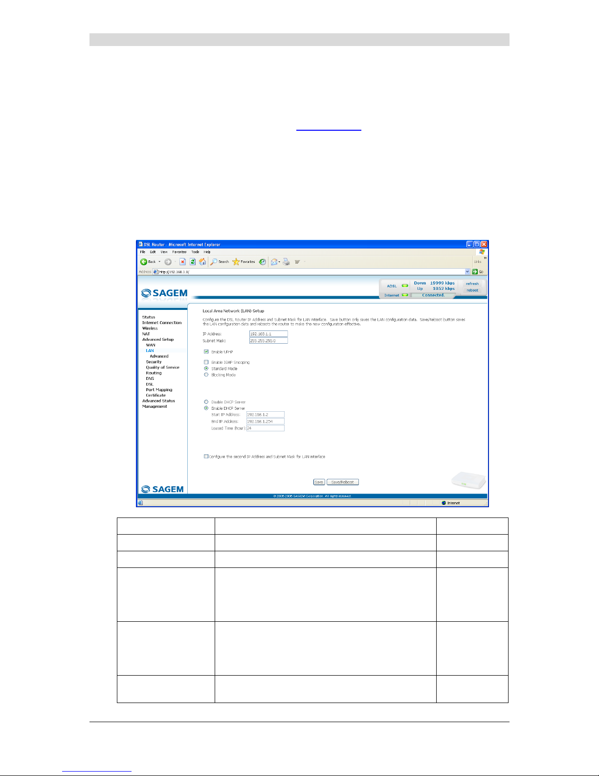
2) Status of the DHCP server
To obtain this status:
• Open your browser and then enter http://myrouter
or http://192.168.1.1 (default
IP address of your Residential Gateway) to access the welcome screen,
• Enter "admin" in the "User Name" field (see note).
• Enter "admin" in the "Password" field (see note).
• Then click on the "OK" button to validate.
Note: This value depends on the level of security. The ISP gives users this one.
• Click the "LAN" menu of the heading Advanced Setup; the following screen appears:
Field Meaning Display
IP Address
Displays the sub-network address 192.168.1.1
Subnet Mask
Displays the sub-network mask of the IP network. 255.255.255.0
Start IP Address
Displays the first address attributed by the DHCP
server.
Note : This IP addres s must belong to the same
sub-network as that of the local network.
192.168.1.2
End IP Address
Displays the last address attributed by the DHCP
server.
Note : This IP addres s must belong to the same
sub-network as that of the local network.
192.168.1.254
Leased Time (hour)
Displays the period for obtaining (in hours) an IP
address for a terminal.
24
Page 35

4 - Configuration of network parameters
F@st™ 2804v2 Reference Manual - 253329475-A
Sagemcom document. Reproduction and disclosure prohibited Page 4-5
3) Data of the DHCP client
To obtain this data:
In Windows XP, 2000 and Me
¾ Click the Start button, select Execute, enter cmd and then click OK; the command prompt
screen appears. Enter ipconfig /all (or ipconfig/all) then confirm by pressing Enter.
Page 36

4 - Configuration of network parameters
F@st™ 2804v2 Reference Manual - 253329475-A
Page 4-6 Sagemcom document. Reproduction and disclosure prohibited
Page 37

F@st™ 2804v2 Reference Manual - 253329475-A
Sagemcom document. Reproduction and disclosure prohibited Page 5-1
5. Information / Configuration
This section covers ¾ Accessing the welcome screen § 5.1
¾ Recommendations for using the configuration screens § 5.2
¾ The ADSL connection status §.5.3
¾ Indications displayed on the display frame locate d in the
HTTP configurer window
§ 5.4
¾ The "Status" section § 5.5
¾ The "Internet Connection" section § 5.6
¾ The "Wireless" section § 5.7
¾ The "NAT" section § 5.8
¾ The "Advanced Setup" section § 5.9
¾ The "Advanced Status" section § 5.10
¾ The "Management" section § 5.11
Page 38

5 - Information / Configuration
F@st™ 2804v2 Reference Manual - 253329475-A
Page 5-2 Sagemcom document. Reproduction and disclosure prohibited
5.1 Accessing the welcome screen
To access this screen, you must have configured one of your computer's interfaces
using the installation CD-ROM provided with your router:
• F@st
TM
2804v2 see chapter 3.
If you are using your computer's Ethernet card to configure your router, connect it to an Ethernet
port (ETH1 to ETH4)).
Your router is then configured using a simple Web browser (e.g. Internet Explorer).
The router's DHCP server function is activated by default with an address range
defined as indicated in subsection.5.9.2.
To access the configurer, proceed as follows:
1
In the Start menu, select All Programs / F@st 2804v2, then left click on
.
2
The following screen asks you to connect.
Enter admin by default in the "Username" field.
Enter admin by default in the "Password" field.
Then click on OK to confirm.
Note: The equipment's IP address (192.168.1.1) appears in the bar at the top of the
screen.
Page 39

5 - Information / Configuration
F@st™ 2804v2 Reference Manual - 253329475-A
Sagemcom document. Reproduction and disclosure prohibited Page 5-3
3
Your computer's Web browser opens and displays the router's welcome screen.
The equipment's name is displayed in title (F@st
TM
2804v2).
Equipment configuration sections appear in the left hand side of the welcome
screen.
This screen displays:
) in the centre, an area which shows the current ADSL connection status (see
subsection 5.3).
) in the top right, a display box which lets you know the status of the ADSL line, lets you
refresh the window displayed and restart your router at any time (see subsection 5.4).
) to the left, a list of 7 sections (see subsection 5.5 to 5.11) made up of menus and sub-
menus. These let you view and configure your router's parameters.
You can modify the password to access your router's configurer to optimise the
safety of your network.
Page 40

5 - Information / Configuration
F@st™ 2804v2 Reference Manual - 253329475-A
Page 5-4 Sagemcom document. Reproduction and disclosure prohibited
5.2 Recommendations
The meaning of the main buttons most commonly present in all the configuration windows is
provided in the table below.
Click on this button to add a new window to fill in the fields used to add
an object.
Click on this button to return to the previous screen.
Click on this button to close the active window and return to the main
screen.
Click on this button to display a new window to modify the fields that can
be accessed for a previously selected object.
Click on this button to display the next screen.
Click on this button to remove a selected object from a list.
Note: You must check the "Remove" box to delete this object.
Click on this button to save the entry in the router's non-volatile (flash)
memory.
Note: This value will only be taken into account when you restart your
router.
Click on this button to save the entry in the router's non-volatile (flash)
memory.
Note: This value will be taken into account immediately without you
having to restart your router.
Click on this button to save the entry in the router's non-volatile (flash)
memory then restart your computer.
Basic principles
1) To make this guide easier to read and understand, it does not state that each time you enter
information into a screen you must click on Save or Save/Apply or Save/Reboot (except,
of course, if this is necessary).
2) When you select a section, the screen for the first menu in the section is displayed. In the
same way, when you select a menu, the screen for the first sub-menu is displayed.
3) All the fields in the different screens are explained in a table.
Page 41

5 - Information / Configuration
F@st™ 2804v2 Reference Manual - 253329475-A
Sagemcom document. Reproduction and disclosure prohibited Page 5-5
5.3 ADSL connection status
Refer to subsection 5.5.1 - Status/Summary.
5.4 Display frame
This supervision box is displayed permanently at the top right of each HTTP configurer window .
The objects it contains are explained below.
LEDs
Green
Synchronised ADSL line
Yellow
ADSL line synchronising
Red
ADSL line not connected
Green Connected
Public address (WAN) distributed to the
router.
Yellow Waiting for ISP
ADSL line synchronising or public address
(WAN) not distributed to the router
ADSL Down
Public address (WAN) not distributed to the
router, or ADSL line not synchronised.
Not configured
No VC (Virtual Channel) configured
Off
Router Rebooting
Router restarted
Red Access denied
Wrong Login and/or Password
Transmission rates
Displays the nominal down line transmission rate
Displays the nominal up line transmission rate
Buttons
Allows data displayed on the screen to be refreshed
Allows your router to be started
Page 42
5 - Information / Configuration
F@st™ 2804v2 Reference Manual - 253329475-A
Page 5-6 Sagemcom document. Reproduction and disclosure prohibited
5.5 Status
Clicking on this heading displays the following menus:
• Summary (see subsection 5.5.1),
• Diagnostics (see subsection 5.5.2).
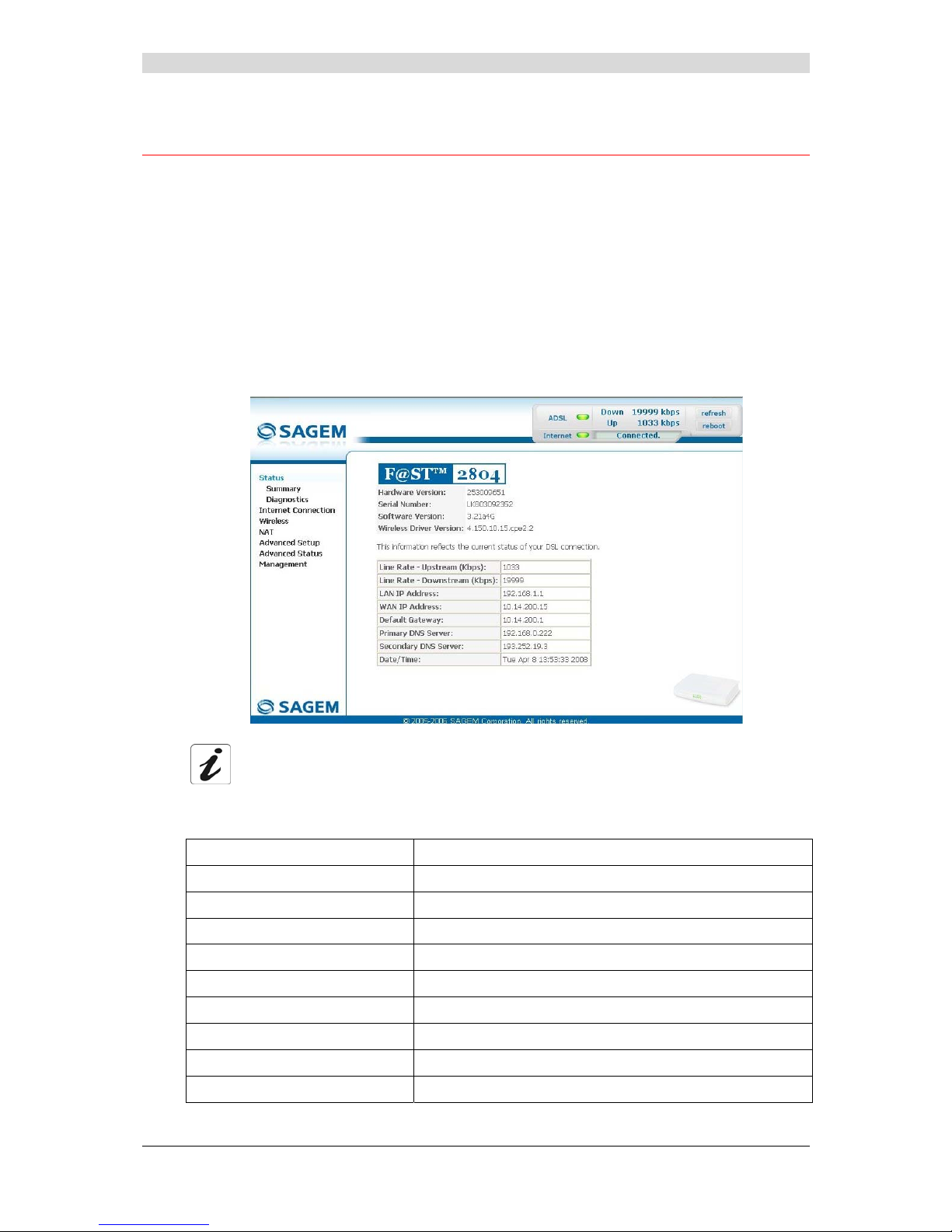
5.5.1 Summary
Object: This menu lets you display the current status of your Internet connection.
• Select the Summary menu in the Status section; the following screen opens:
This screen also appears in the welcome screen (see subsection 5.1).
The following table provides the meaning of the different fields which are displayed.
Field Meaning
Software Version
Software version currently installed.
Line Rate - Upstream (kbps)
Nominal up line rate
Line Rate - Downstream (kbps)
Nominal down line rate
LAN IP Address
Local network IP address (LAN)
WAN IP Address
Remote network IP address (WAN)
Default Gateway
Default gateway address
Primary DNS Server
Primary DNS server address
Secondary DNS Server
Secondary DNS server address
Date / Time
Date and Time (see Note)
Page 43

5 - Information / Configuration
F@st™ 2804v2 Reference Manual - 253329475-A
Sagemcom document. Reproduction and disclosure prohibited Page 5-7
Note: This field only appears if the "Automatically synchronize with Internet time
servers" box is checked in the "Management / Internet Time" menu
(see subsection 5.11.5).
5.5.2 Diagnostics
Object: This menu is used to display all the tests performed on the connections made from
your router to your Internet Service Provider (ISP). These tests concern:
• connection to your local network (LAN),
• connection to your "DSL Service Provider",
• connection to your "Internet Service Provider".
A hypertext link (help) enables the user to access context-related help. This help
gives an explanation concerning the state of the connection (PASS in green, DOWN
in orange and FAIL in red) and supplies the appropriate troubleshooting procedures.
The ADSL line translates the three statuses detailed in the table below.
State Colour Meaning
PASS Green
Indicates that the test was completed successfully.
DOWN Orange
Indicates that an interface (ETH, Wi-Fi) has not been detected.
FAIL Red
Indicates that the test has failed, or that it is impossible to start a
command.
If a test displays a "FAIL" status, click on "Help" and then the button
"Rerun Diagnostic Tests" at the bottom of the "Help" page, to check that the test
has been conclusive. If the test still displays "FAIL", you must follow the
troubleshooting procedure displayed on this page.
Page 44

5 - Information / Configuration
F@st™ 2804v2 Reference Manual - 253329475-A
Page 5-8 Sagemcom document. Reproduction and disclosure prohibited
• Select the Diagnostics menu in the Status section; the following screen opens:
Page 45
5 - Information / Configuration
F@st™ 2804v2 Reference Manual - 253329475-A
Sagemcom document. Reproduction and disclosure prohibited Page 5-9
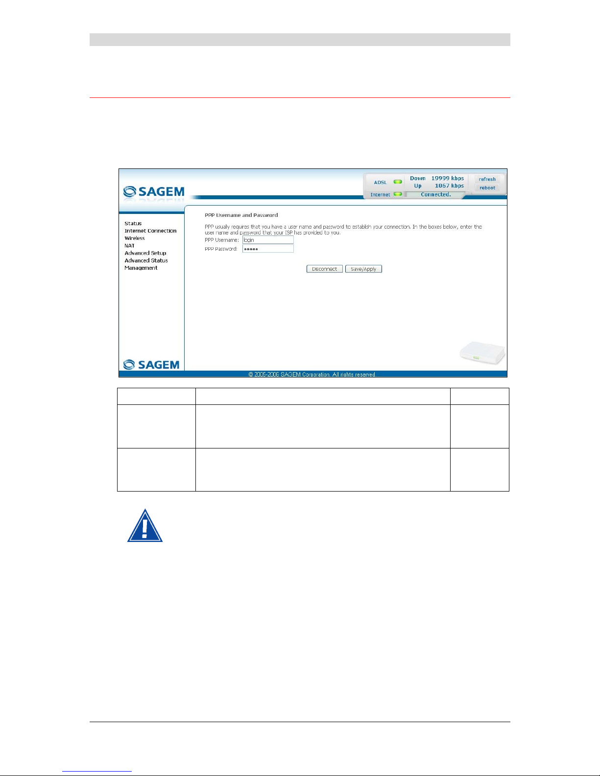
5.6 Internet Connection
Object: This menu lets you enter your connection ID and your connection password.
• Select the Internet Connection heading to display the following connection configuration
screen:
Field Action Default:
PPP Username
Enter your connection ID.
This information is provided to you by your Internet Service
Provider (ISP).
Empty
PPP Password
Enter your connection password.
This information is provided to you by your Internet Service
Provider (ISP).
Empty
If the message "There is no ppp connection" appears, this means that the
remote network (WAN) parameters have not been filled in (see subsection 5.9.1 Advanced Setup / WAN).
Disconnect
When you click on the button “Disconnect”:
• Internet access is no longer possible.
• In the supervision box, indicator “Internet” passes from the green to the yellow and the text
“Connected” is replaced by “Waiting for ISP”.
• On the front panel, the indicator @ goes out.
Page 46
5 - Information / Configuration
F@st™ 2804v2 Reference Manual - 253329475-A
Page 5-10 Sagemcom document. Reproduction and disclosure prohibited
5.7 Wireless
Object: This menu lets you activate a network and also allows you to configure all the basic
and advanced parameters of a wireless network.
This section contains the following five menus:
• Basic (see subsection 5.7.1),
• Security (see subsection 5.7.2),
• MAC Filter (see subsection 5.7.3),
• Advanced (see subsection 5.7.4),
• Quality of Service (see subsection 5.7.5).
The Security, MAC Filter, Advanced and Quality of Service menus are used
to configure the advanced parameters in the Wireless section. These menus are
only displayed if, in the Basic menu, the "Enable Advanced Wireless
Configuration" box is checked (not checked by default).
These menus must only be accessed/modified by experienced users.
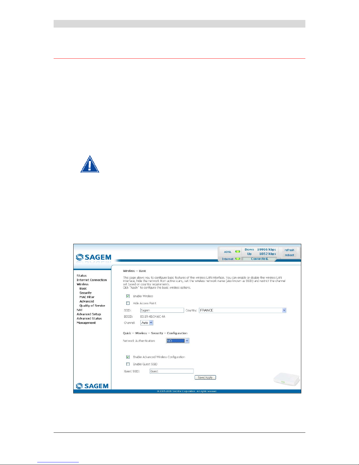
5.7.1 Basic
• Select the Basic menu in the Wireless section to display the following wireless network
configuration screen:
Page 47

5 - Information / Configuration
F@st™ 2804v2 Reference Manual - 253329475-A
Sagemcom document. Reproduction and disclosure prohibited Page 5-11
5.7.1.1 Wireless - Basic
Field Action/Meaning Default:
Enable Wireless
Check the appropriate box to activate the wireless
network (Wi-Fi).
Note: The steady "Wi-Fi" LED on the front of the
router shows that the wireless network (Wi-Fi)
is activated.
Box
checked
Hide Access Point
Check the appropriate box to mask the broadcast of the
SSID and prevent any Wi-Fi connection on your router.
Note: When this box is checked, the router's SSID is
absent from the Wi-Fi adaptor user's own list of
monitored sites (Access Point).
Box not
checked
SSID
Enter your router's SSID.
Note: This is indicated on the label stuck to the box.
Sagem
Country
Select the country of your choice from the scroll down
list.
FRANCE
BSSID
This is the MAC address of the router's Wi-Fi interface
(Access Point). In the "Structure" mode, this address
identifies a cell (BSS in English Basic Service Set).
This cell is a set formed by the access point and the
stations located in its coverage area.
Non modifiable
_
Channel
This is the radio channel used by the router and
its Wi-Fi clients to communicate with each other. This
channel must be the same for the router and all its
Wi-Fi clients.
Select the channel you want from the scroll down list
(auto, channels 1 to 13).
Note: Channel 11 corresponds to frequency
2462 MHz.
Note: If you select "Auto", the Wi-Fi equipment will
select the access point channel (router) which
will emit the strongest signal.
You will find an identical "Channel" field in the
"Advanced" menu of this same section. Any
modifications are carried over from one field to
another.
Conform to the CE Declaration of conformity / Radio
rules list in appendix B to paragraph B.2.
Auto
Page 48

5 - Information / Configuration
F@st™ 2804v2 Reference Manual - 253329475-A
Page 5-12 Sagemcom document. Reproduction and disclosure prohibited
5.7.1.2 Quick Wireless - Security - Configuration
Field Action/Meaning Default:
Network
Authentication
From the scroll down list, select the security adapted
to your router's wireless network. The list suggests the
following choices:
• NO : There is no protection for the wireless
network,
• WEP : Activation of WEP (Wired
Equivalent Privacy) encryption
• WPA-PSK : Activation of the WPA
(Wireless Protected Access)
• WPA2-PSK : Activation of the WPA2
(Wireless Protected Access)
• Other (see subsection 5.7.2.1).
NO
Note: The router may or may not be secured, at the request of the customer. This level of
security is indicated on the label pasted to the box.
This choice will modify the Wireless configuration screen.
Page 49
5 - Information / Configuration
F@st™ 2804v2 Reference Manual - 253329475-A
Sagemcom document. Reproduction and disclosure prohibited Page 5-13
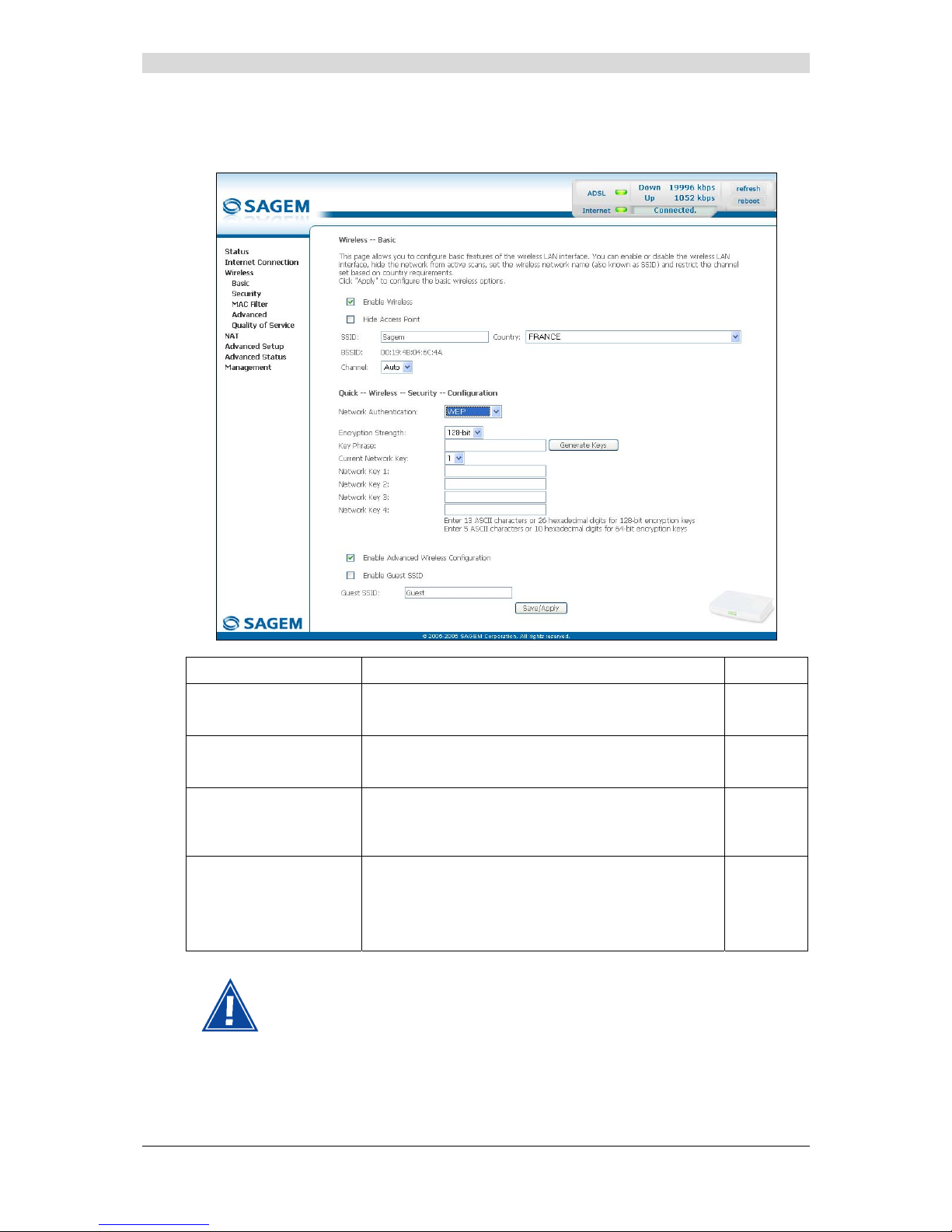
WEP
• Select the "WEP" encryption mode from the scroll down list; the following screen appears:
Field Action/Meaning Default:
Encryption Strength
Select 64-bit or 128-bit for an encryption at 64 bits or
128 bits respectively.
128-bit
Key phrase
Enter a phrase that consists of up to 15 alphanumeric
characters then click the Generate Keys button.
Empty
Current network key
Select a key from the four suggested. The emission
key is used to encrypt the data sent by your
computer.
1
Network key x (1 to 4)
The WEP key is customised for your router.
You may modify the keys by entering them directly
into the boxes.
The characters are "0" to "9" and "A" to "F".
Empty
Store the key phrase and the keys in a safe location.
Do not write them in a file on your computer.
Page 50

5 - Information / Configuration
F@st™ 2804v2 Reference Manual - 253329475-A
Page 5-14 Sagemcom document. Reproduction and disclosure prohibited
You may automatically generate encryption keys or manually enter the keys.
The "Key phrase" can consist of up to 15 alphanumeric characters.
To manually configure the encryption key, enter five hexadecimal pairs of digits for
each 64-bit key, or enter 13 pairs for the single 128-bit key (A hexadecimal digit is
a number or letter in the range 0-9 or A-F). Note that the WEP key protects data
transmitted between wireless nodes, but does not protect any transmissions over
your wired network (LAN) or over Internet (WAN) using Internet Explorer 5.0 or
above.
WPA-PSK
See subsection 5.7.2.1 - WPA-PSK
WPA2-PSK
See subsection 5.7.2.1 - WPA2-PSK
Other
See subsection 5.7.2.1.
Advanced Wireless
Field Meaning Default
Enable advanced
Wireless Configuration
Check the appropriate box to be able to display the
Security, MAC Filter, Advanced and
Quality of Service menus in the "Wireless" section.
Note: If you check this box, the "Enable Guest SSID"
and "Guest SSID" fields appear.
Box not
checked
Enable Guest SSID
Check the appropriate box to activate the "Guest SSID".
Box not
checked
Guest SSID
Enter a name for the "Guest SSID".
Guest
Page 51

5 - Information / Configuration
F@st™ 2804v2 Reference Manual - 253329475-A
Sagemcom document. Reproduction and disclosure prohibited Page 5-15
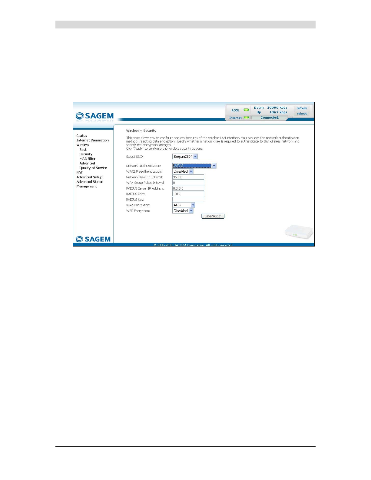
5.7.2 Security
Object: The purpose of this menu is to secure your wireless network (Wi-Fi). All types of
ingenious solutions have been deployed to combat attacks from hackers. Encryption
modes have been implemented to secure your wireless network. Among these, two
are commonly used:
¾ WEP (Wired Equivalent Protocol),
¾ WPA (Wi-Fi Protected Access) and its derivatives (WPA-PSK, WPA2 etc.).
The WPA encryption mode is the most robust and the best adapted to correctly
securing your wireless network.
• Select the Security menu in the Wireless section to display the following screen:
Page 52

5 - Information / Configuration
F@st™ 2804v2 Reference Manual - 253329475-A
Page 5-16 Sagemcom document. Reproduction and disclosure prohibited
Field Meaning Default
Select SSID
Select the "SSID" of your choice from the scroll
down list (sagem or Guest).
sagem
Network Authentication
From the scroll down list, select the security
adapted to your router's wireless network. The list
suggests the following choices:
• Open : There is no protection for the wireless
network (Open System).
• Shared :
• 802.1x : Activation of the 802.1x standard,
• WPA : Activation of WPA (Wireless Protected
Access),
• WPA-PSK : Activation of WPA-PSK,
• WPA2 : Activation of WPA2,
• WPA2-PSK : Activation of WPA2-PSK,
• Mixed WPA2/WPA : Activation of
Mixed WPA2/WPA,
• Mixed WPA2/WPA-PSK : Activation of
Mixed WPA2/WPA-PSK,
This choice will modify the Wireless configuration
screen.
Open
WEP Encryption
Select from the scroll down list:
• Disabled to not use WEP encryption.
• Enabled to use WE encryption
(see subsection 5.7.1.2 - WEP).
Disabled
Page 53

5 - Information / Configuration
F@st™ 2804v2 Reference Manual - 253329475-A
Sagemcom document. Reproduction and disclosure prohibited Page 5-17
5.7.2.1 Network Authentication
The scroll down list in the "Network Authentication" field shows 9 possible
authentication types:
• Open,
• Shared,
• 802.1x,
• WPA,
• WPA-PSK,
• WPA2,
• WPA2-PSK,
• Mixed WPA2/WPA,
• Mixed WPA2/WPA-PSK.
A different screen appears for each authentication type.
Open
Object: The "Open System" authentication enables all users of the Wi-Fi network to
authenticate themselves with the router. No restrictions concerning security are
demanded.
In this authentication mode, only the WEP key may be used to encrypt data.
Page 54

5 - Information / Configuration
F@st™ 2804v2 Reference Manual - 253329475-A
Page 5-18 Sagemcom document. Reproduction and disclosure prohibited
Shared
Object: This level of security enables users of the Wi-Fi network to be authenticated using
their SSID or their WEP key.
In this authentication mode, the WEP key is used to encrypt data.
• Select the "Shared" security from the scroll down list; the following screen appears:
Field Action Default
WEP Encryption
Note: This field is always active (Enabled).
Enabled
(non modifiable)
Encryption Strength
See subsection 5.7.1.2 - WEP.
128-bit
Key Phrase
See subsection 5.7.1.2 - WEP.
Empty
Current Network Key
See subsection 5.7.1.2 - WEP.
2
Network Key x (1 to 4)
See subsection 5.7.1.2 - WEP.
Empty
Page 55

5 - Information / Configuration
F@st™ 2804v2 Reference Manual - 253329475-A
Sagemcom document. Reproduction and disclosure prohibited Page 5-19
802.1x
Object: The "802.1x" standard is based on the EAP protocol (Extensible Authentication
Protocol). This enables users of the Wi-Fi network to be authenticated using a
"RADIUS" authentication server (Remote Authentication Dial-in User Service).
In this case, the WEP key is used exclusively for data encryption.
• Select the security according to the "802.1x" protocol from the scroll down list; the following
screen appears:
Field Action Default
RADIUS Server IP Address
Enter the IP address of the "RADIUS"
authentication server.
0.0.0.0
RADIUS Port
Enter the port used for the "RADIUS"
authentication server.
1812
RADIUS Key
Enter the secret key shared between the
authentication server and its clients
_
WEP Encryption
Note: This field is always active (Enabled).
Enabled
Encryption Strength
See subsection 5.7.1.2 - WEP.
128-bit
Key Phrase
See subsection 5.7.1.2 - WEP.
Empty
Current Network Key
Select key 2 or 3
(see subsection 5.7.1.2 - WEP).
2
Page 56
5 - Information / Configuration
F@st™ 2804v2 Reference Manual - 253329475-A
Page 5-20 Sagemcom document. Reproduction and disclosure prohibited
Field Action Default
Network Key x (1 to 4) 1
This field is empty or displays the key
value entered earlier (greyed out)
Non modifiable
2
Enter the encryption on the key you
selected in the "Current Key"
(see subsection 5.7.1.2- WEP).
3
Enter the encryption on the key you
selected in the "Current Key"
(see subsection 5.7.1.2- WEP).
4
This field is empty or displays the key
value entered earlier (greyed out)
Non modifiable
Page 57

5 - Information / Configuration
F@st™ 2804v2 Reference Manual - 253329475-A
Sagemcom document. Reproduction and disclosure prohibited Page 5-21
WPA
Object: This encryption mode applies the functionalities of the WPA protocol and requires the
use of a "RADIUS" authentication server.
• Select the "WPA" security from the scroll down list; the following screen appears:
Field Action Default
WPA Group Rekey Interval
Enter a value (in seconds) which determines
the period after which the WPA key will be
regenerated (Renewing) in broadcast /
multicast (LAN broadcast).
0
RADIUS Server IP Address
Enter the IP address of the "RADIUS"
authentication server.
0.0.0.0
RADIUS Port
Enter the port used by the "RADIUS"
authentication server.
1812
RADIUS Key
Enter the secret key shared between the
authentication server and its clients
_
WPA encryption
Select the WPA encryption required from the
scroll down list:
• TKIP (Temporal Key Integration
Protocol),
• AES (Advanced Encryption Standard),
• TKIP+ AES.
TKIP
Page 58

5 - Information / Configuration
F@st™ 2804v2 Reference Manual - 253329475-A
Page 5-22 Sagemcom document. Reproduction and disclosure prohibited
Field Action Default
WEP encryption
Select from the scroll down list:
• Disabled to use WPA encryption only.
• Enabled to use both WPA and WEP
encryption
(see subsection 5.7.1.2 - WEP).
Disabled
Page 59

5 - Information / Configuration
F@st™ 2804v2 Reference Manual - 253329475-A
Sagemcom document. Reproduction and disclosure prohibited Page 5-23
WPA-PSK
Object: This encryption mode applies the functionalities of the WPA protocol with a pre-shared
key, but does not require an authentication server. The key is regenerated after a
period which can be configured (WPA Group Rekey Interval).
• Select the "WPA-PSK" security from the scroll down list; the following screen appears:
Field Action Default
WPA Pre-Shared Key
Enter the secret shared key. This may contain 8
to 63 ASCII characters or 64 hexadecimal
symbols (256 bits).
Click on the "Save/Apply" button to validate the
entry.
Note: You may display your secret phrase by
clicking on "Click here to display".
Empty
WPA Group Rekey Interval
Enter a value (in seconds) which determines
the period after which the WPA key will be
regenerated (Renewing) in broadcast /
multicast (LAN broadcast).
0
WPA encryption
Select the WPA encryption required from the
scroll down list:
• TKIP,
• AES,
• TKIP+ AES.
TKIP
Page 60

5 - Information / Configuration
F@st™ 2804v2 Reference Manual - 253329475-A
Page 5-24 Sagemcom document. Reproduction and disclosure prohibited
Field Action Default
WEP encryption
Select from the scroll down list:
• Disabled to use WPA encryption only.
• Enabled to use both WPA and WEP
encryption
(see subsection 5.7.1.2 - WEP).
Disabled
Page 61
5 - Information / Configuration
F@st™ 2804v2 Reference Manual - 253329475-A
Sagemcom document. Reproduction and disclosure prohibited Page 5-25
WPA2
Object: This encryption mode applies the functionalities of the WPA2 protocol and requires
the use of a "RADIUS" authentication server.
• Select the "WPA2" security from the scroll down list; the following screen
appears:
Page 62

5 - Information / Configuration
F@st™ 2804v2 Reference Manual - 253329475-A
Page 5-26 Sagemcom document. Reproduction and disclosure prohibited
Field Action Default
WPA2 Preauthentication-
Select from the scroll down list:
• Disabled to deactivate the
WPA2 pre-authentication,
• Enabled to activate the
WPA2 pre-authentication,
Disabled
Network Re-auth Interval
Enter a value (in seconds) which determines
the period after which the WPA key will be
certified.
36000
WPA Group Rekey Interval
Enter a value (in seconds) which determines
the period after which the WPA key will be
regenerated (Renewing) in broadcast /
multicast (LAN broadcast).
0
RADIUS Server IP Address
Enter the IP address of the "RADIUS"
authentication server.
0.0.0.0
RADIUS Port
Enter the port used by the "RADIUS"
authentication server.
1812
RADIUS Key
Enter the secret key shared between the
authentication server and its clients.
_
WPA encryption
Select the WPA encryption required from the
scroll down list:
• TKIP,
• AES,
• TKIP+ AES.
AES
WEP encryption
Select from the scroll down list:
• Disabled to use WPA encryption only.
• Enabled to use both WPA and WEP
encryption
(see subsection 5.7.1.2 - WEP).
Disabled
Page 63

5 - Information / Configuration
F@st™ 2804v2 Reference Manual - 253329475-A
Sagemcom document. Reproduction and disclosure prohibited Page 5-27
WPA2-PSK
Object: This encryption mode uses the WPA2 protocol with a pre-shared key, but does not
require an authentication server. The key is regenerated after a period which can be
configured (WPA Group Rekey Interval).
• Select the "WPA2-PSK" security from the scroll down list; the following screen
appears:
Field Action Default
WPA Pre-Shared Key
Enter a secret phrase. This may contain 8 to 63
ASCII characters or 64 hexadecimal symbols
(256 bits).
Click on the "Save/Apply" button to validate the
entry.
Note: You may display your secret phrase by
clicking on "Click here to display".
Empty
WPA Group Rekay Interval
Enter a value (in seconds) which determines
the period after which the WPA key will be
regenerated (Renewing) in broadcast /
multicast (LAN broadcast).
0
WPA encryption
Select the WPA encryption required from the
scroll down list:
• TKIP,
• AES,
• TKIP+ AES.
AES
Page 64

5 - Information / Configuration
F@st™ 2804v2 Reference Manual - 253329475-A
Page 5-28 Sagemcom document. Reproduction and disclosure prohibited
Field Action Default
WEP encryption
Select from the scroll down list:
• Disabled to use WPA encryption only.
• Enabled to use both WPA and WEP
encryption
(see subsection 5.7.1.2 - WEP).
Disabled
Page 65

5 - Information / Configuration
F@st™ 2804v2 Reference Manual - 253329475-A
Sagemcom document. Reproduction and disclosure prohibited Page 5-29
Mixed WPA2/WPA
Object: This encryption mode applies the functionalities of the WPA2 and WPA protocols. It
needs a "RADIUS" authentication server.
• Select the "Mixed WPA2/WPA" security from the scroll down list; the following screen
appears:
Field Action Default
WPA2 Preauthentication-
Select from the scroll down list:
• Disabled to deactivate the
WPA2 pre-certification,
• Enabled to activate the
WPA2 pre-certification,
Disabled
Network Re-auth Interval
Enter a value (in seconds) which determines
the period after which the WPA key will be
certified.
36000
WPA Group Rekey Interval
Enter a value (in seconds) which determines
the period after which the WPA key will be
regenerated (Renewing) in broadcast /
multicast (LAN broadcast).
0
RADIUS Server IP Address
Enter the IP address of the "RADIUS"
authentication server.
0.0.0.0
RADIUS Port
Enter the port used by the "RADIUS"
authentication server.
1812
RADIUS Key
Enter the secret key shared between the
authentication server and its clients
_
Page 66

5 - Information / Configuration
F@st™ 2804v2 Reference Manual - 253329475-A
Page 5-30 Sagemcom document. Reproduction and disclosure prohibited
Field Action Default
WPA encryption
Select the WPA encryption required from the
scroll down list:
• TKIP,
• AES,
• TKIP+ AES.
TKIP+AES
WEP Encryption
Select from the scroll down list:
• Disabled to not use WEP encryption.
• Enabled to use WE encryption
(see subsection 5.7.1.2 - WEP).
Disabled
Page 67

5 - Information / Configuration
F@st™ 2804v2 Reference Manual - 253329475-A
Sagemcom document. Reproduction and disclosure prohibited Page 5-31
Mixed WPA2/WPA-PSK
Object: This encryption mode applies the functionalities of the WPA2-PSK and WPA-PSK
protocols. It does not need a "RADIUS" authentication server.
• Select the "Mixed WPA2 /WPA-PSK" security from the scroll down list; the following screen
appears:
Field Action Default
WPA Pre-Shared Key
Enter a secret phrase. This may contain 8 to
63 ASCII characters or 64 hexadecimal symbols
(256 bits).
Click on the "Save/Apply" button to validate the
entry.
Note: You may display your secret phrase by
clicking on "Click here to display".
Empty
Page 68

5 - Information / Configuration
F@st™ 2804v2 Reference Manual - 253329475-A
Page 5-32 Sagemcom document. Reproduction and disclosure prohibited
Field Action Default
WPA Group Rekey Interval
Enter a value (in seconds) which determines
the period after which the WPA key will be
regenerated (Renewing) in broadcast /
multicast (LAN broadcast).
0
WPA encryption
Select the WPA encryption required from the
scroll down list:
• TKIP,
• AES,
• TKIP+ AES.
TKIP+ AES
WEP Encryption
Select from the scroll down list:
• Disabled to not use WEP encryption.
• Enabled to use WE encryption
(see subsection 5.7.1.2 - WEP).
Disabled
Page 69
5 - Information / Configuration
F@st™ 2804v2 Reference Manual - 253329475-A
Sagemcom document. Reproduction and disclosure prohibited Page 5-33
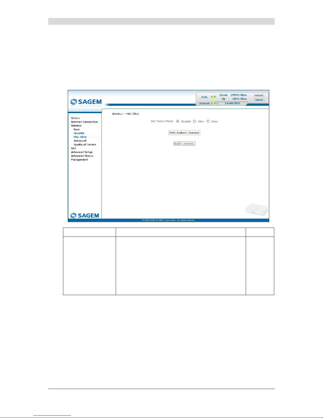
5.7.3 MAC Filter
Object: The "MAC Filter" function is used to limit the number of computers which can access
your wireless network.
• Select the MAC Filter menu in the Wireless section to display the following screen:
Field Meaning Default
MAC Restrict Mode
Select the command by checking the appropriate box:
Disabled : Deactivates the MAC filtering,
Allow : Enables computers whose MAC address
is in the list to use your wireless network,
Denied : Refuses computers whose MAC address
is in the list to use your wireless network.
Disabled
Page 70

5 - Information / Configuration
F@st™ 2804v2 Reference Manual - 253329475-A
Page 5-34 Sagemcom document. Reproduction and disclosure prohibited
Add
• Click on the Add button to add a MAC address to be filtered (address of a computer
authorised to connect to a wireless network).
Note: The MAC address can be added automatically at the time of the Wi-Fi installation, by
a short push on button “REG”.
After approximately 5 minutes, the new address fits in the list and F@st
TM
2604
passes in mode of filtering (MAC Restrict Mode) “Allow” to authorize only the
computers whose MAC address appears in the list to be connected to your router.
Page 71
5 - Information / Configuration
F@st™ 2804v2 Reference Manual - 253329475-A
Sagemcom document. Reproduction and disclosure prohibited Page 5-35
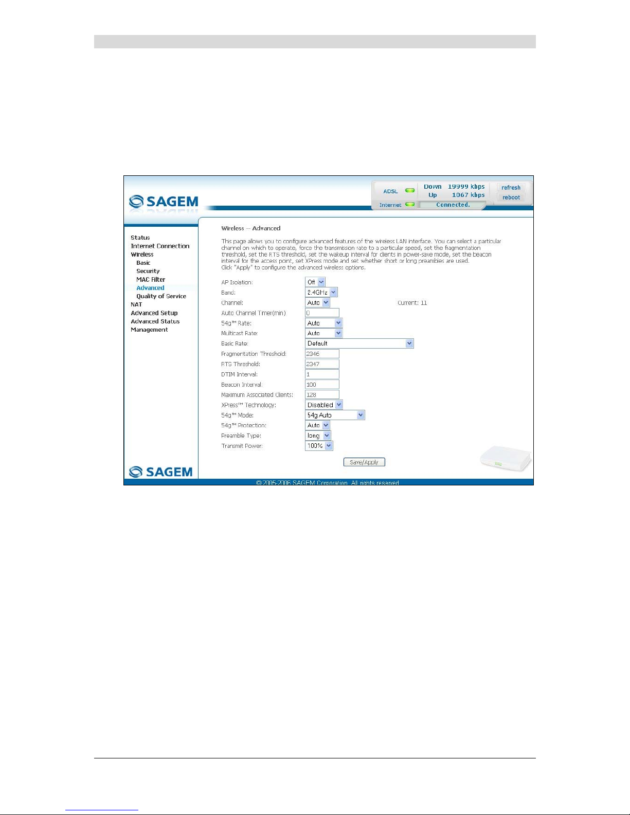
5.7.4 Advanced
Object: This menu is used to configure the essential parameters of your wireless network
(WLAN) 802.11 and configure certain security parameters.
• Select the Advanced menu in the Wireless section to display the following screen:
Page 72

5 - Information / Configuration
F@st™ 2804v2 Reference Manual - 253329475-A
Page 5-36 Sagemcom document. Reproduction and disclosure prohibited
The table below indicates in more detail how to access your Wi-Fi port
(or Access Point).
Nevertheless, it is best to leave the default values for easier usage.
Field Meaning Default
AP Isolation
Select from the scroll down list:
Off : to not isolate the Access Point i.e.
authorise machines connected to the
router to communicate with each other.
On : to isolate the Access point, i.e. prohibit
machines connected to the router to
communicate with each other.
Off
Band
Select the 2.4 GHz band for the IEEE 802.11g
standard.
2.4GHz-
802.11g
Channel
See Wireless/Basic subsection 5.7.1.1.
Auto
Auto Channel Timer (min)
Configure the duration, in minutes, during which
the router must seek the best wireless channel.
This option is only available when the selection of
the channel is configured in “Auto” (Automatic).
0
54gTM Rate
In the scroll down list, select the transmission rate
at which the information (data or video) will be
transmitted or received on your wireless network
(Auto, 1, 2, 5.5, 6, 9, 11, 12, 18, 24, 36, 48 or
54 Mbps).
Note: If you select "Auto", the information will
be transmitted at an optimised rate
which takes account of the transmission
constraints.
Auto
Multicast Rate
From scroll down list, select the transmission rate
at which the "Multicast" packets are transmitted
(Auto, 1, 2, 5.5, 6, 9, 11, 12, 18, 24, 36, 48 or
54 Mbps).
Note: If you select "Auto", the information will
be transmitted at an optimised rate
which takes account of the transmission
constraints.
Video conferencing and teleconferencing are
"Multicast" applications.
Auto
Basic Rate
From the scroll down list, select the basic rate at
which the information will be transmitted or
received over your wireless network (Default, All,
1 & 2 Mbps or 1 & 2 & 5.5 & 6 & 11 & 12 &
24 Mbps).
Default
Fragmentation Threshold
This packet fragmentation mechanism is used to
limit errors and repetitions.
It is recommended not to reduce the packet size
too much to avoid reducing the bandwidth.
Enter a threshold value (in bytes) between 256
and 2347.
2346
Page 73

5 - Information / Configuration
F@st™ 2804v2 Reference Manual - 253329475-A
Sagemcom document. Reproduction and disclosure prohibited Page 5-37
Field Meaning Default
RTS Threshold
The RTS/CTS protocol (Request To Send / Clear
To Send) is used to reduce the probability of
collisions between stations.
Note: As packet size is set by default to 2346,
the RTS/CTS protocol is inhibited as its
value is set by default to 2347.
Enter a threshold value (in bytes) between 1 and
2347.
2347
DTIM Interval
The DTIM counting area (Delivery Traffic Indication
Message) enables Wi-Fi clients to listen to
broadcast and multicast messages saved in your
router's "Buffer" memory.
Enter an interval value (in seconds) between 1
and 255.
1
Beacon Interval
Enter a time interval value between two beacon
signals which shows the activity of the wireless
network.
This interval value (in milliseconds) is between 1
and 1000.
100
Maximum Associated
Clients
Enter the maximum number wireless customers
for your router.
128
XPressTM Technology
From the scroll down list, select Enabled to apply
the "XPress
TM
" technology or Disabled to not
apply it.
Disabled
54gTM Mode
In the scroll down list, select (54g Auto, 54g
Performance, 54g LRS or 802.11b Only)
54g Auto
54g Protection
Select Auto to improve the quality in the mixed
802.11 environments (g and b for example) or Off
to improve the quality only on the 802.11g
environments but degrade it on other
environments (802.11b for example).
Auto
Page 74

5 - Information / Configuration
F@st™ 2804v2 Reference Manual - 253329475-A
Page 5-38 Sagemcom document. Reproduction and disclosure prohibited
Field Meaning Default
Preamble Type
In the IEEE 802.11 standard, the "preamble" is
used to synchronise the Emitter and Receiver
correctly. The "long preamble" is generally
commonly used. For reasons of bandwidth gain,
this standard proposes reducing the length of the
"preamble".
“Preamble Type” defines the length of block CRC
(Cyclical Redundancy Checking).
If your network does not include any peripheral
802.11b, you can configure the type of preamble
on “short” for an optimal result.
The type of preamble “long” must be used if the
peripherals 802.11g and 802.11b are both present
on the network.
In the scroll down list, select long to keep a
128 bit "preamble" or short to reduce it to 56 bits.
long
Transmit Power
If 802.11 h is selected, in the scroll down list
select the cyclical emission ratio (20%, 40 %,
60 %, 80 % or 100 %) at which you want to
transmit.
Note: The power rate will be selected according
to your environment.
100%
Page 75

5 - Information / Configuration
F@st™ 2804v2 Reference Manual - 253329475-A
Sagemcom document. Reproduction and disclosure prohibited Page 5-39
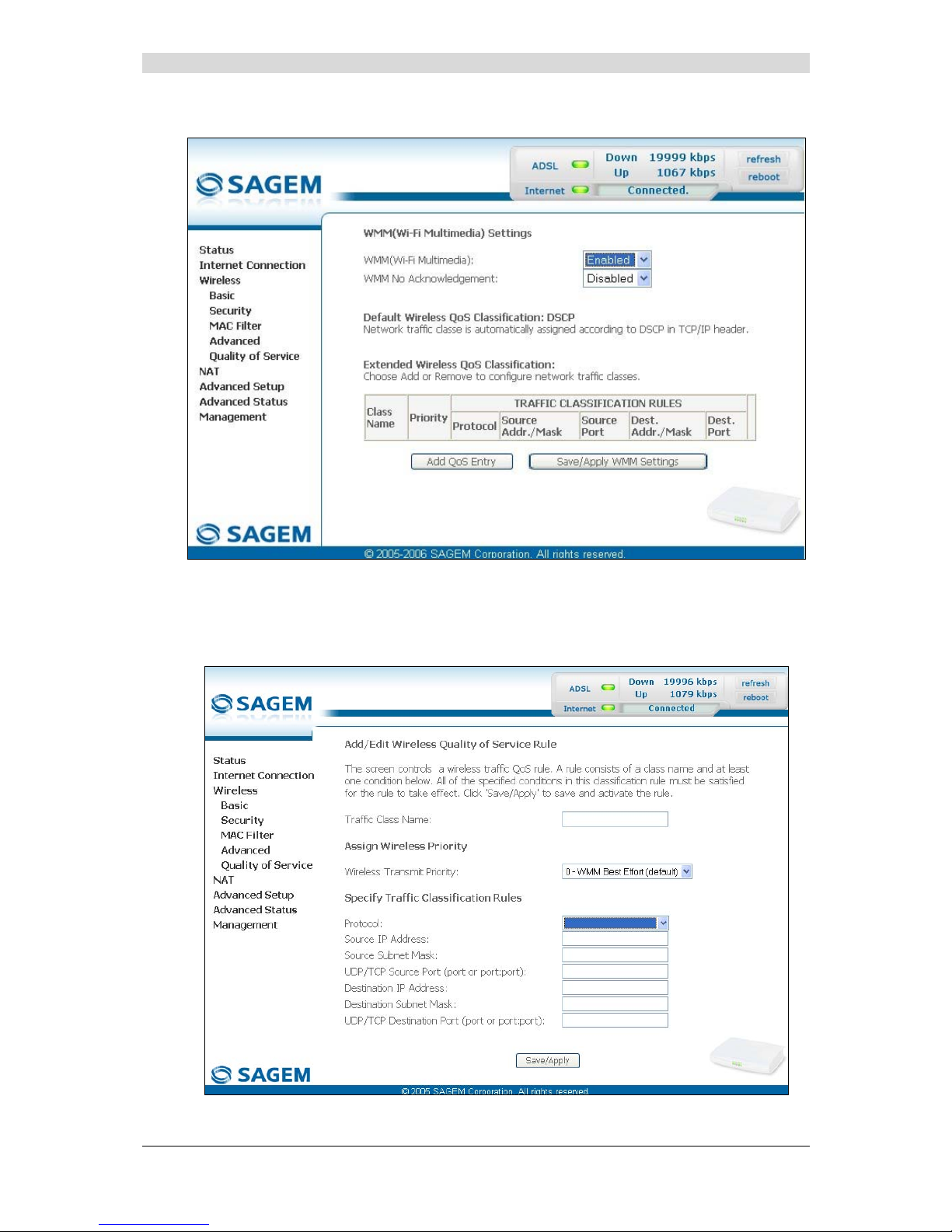
5.7.5 Quality of Service
Object: The Wi-Fi quality of service for your router conforms to the WMM (Wifi MultiMedia)
specification. This standard improves the performances of Wi-Fi links by acting on
the data flows (packet size, bit rates, etc.) and the length of queues while respecting
bandwidth requirements (managed by the router).
• Select the Quality of Service menu in the Wireless section to display the following screen:
Field Meaning Default
WMM (Wi-Fi Multimedia)
In the scroll down list, select the activation
(Enabled) or deactivation (Disabled) of the
WMM support.
Disabled
WMM No Acknowledgement
Note: The scroll down list may only be
operational if the "WMM (Wi-Fi
Multimedia)" field is activated.
In the scroll down list, select Enabled or
Disabled to permit or prohibit a more effective
bit rate of the data flow with, on the other hand,
a higher error rate.
Greyed
out
Page 76
5 - Information / Configuration
F@st™ 2804v2 Reference Manual - 253329475-A
Page 5-40 Sagemcom document. Reproduction and disclosure prohibited
The following screen appears as soon as you activate "WMM".
Add
• Click on the Add QoS Entry button to add a Wi-Fi Quality of Service (wifi QoS) rule; the
following screen appears.
Page 77

5 - Information / Configuration
F@st™ 2804v2 Reference Manual - 253329475-A
Sagemcom document. Reproduction and disclosure prohibited Page 5-41
Field Action Default
Traffic Class Name
Enter a name for the traffic class you want to
create.
Empty
Wireless Transmit Priority
In the scroll down list, select the priority you
want to allocate to the traffic class you
selected (see table below).
0 - WMM
Best Effort
(default)
Protocol
Select the appropriate protocol from the scroll
down list (TCP/UDP, TCP, UDP, ICMP).
Empty
Source IP Address
Enter a Source IP address (LAN).
Empty
Source Subnet Mask
Enter a sub-net mask associated with the
"Source" IP address.
Empty
UDP/TCP Source Port
(port or port:port)
Enter a "Source" port or range of ports.
Note: For one port, for example, enter 80.
For a range of ports, enter 80:90.
Empty
Destination IP Address
Enter a "Destination" IP address (WAN).
Empty
Destination Subnet Mask
Enter a sub-net mask associated with the
"Destination" IP address.
Empty
UDP/TCP Destination Port
(port or port:port)
Enter a "Destination" port or range of ports.
Note: For one port, for example, enter 80.
For a range of ports, enter 80:90.
Empty
Transmission priority Meaning
0 - WMM Best Effort (default)
This is the lowest priority. This provides no guarantee of
data transmission.
1 - WMM Background
2 - WMM Background
These are intermediate priorities. These provide routing
without too much data flow loss.
3 - WMM Best Effort
This priority provides no guarantee of data transmission.
4 - WMM Video priority
5 - WMM Video priority
These are intermediate priorities. They provide a correct
routing for "Video".
6 - WMM Voice priority
7 - WMM Voice priority
These are higher priorities. They provide complete routing
for voice
Click on the
button to save the parameters.
Page 78

5 - Information / Configuration
F@st™ 2804v2 Reference Manual - 253329475-A
Page 5-42 Sagemcom document. Reproduction and disclosure prohibited
5.8 NAT
Object: NAT is a configurable IP address translation function which will be applied to the
interfaces of your router which you will have activated for this function.
Several translation function configurations, the NAT actions, can be configured and
may be activated as indicated in the 5.8.1 - Add paragraph.
This section contains the following four menus:
• Port forwarding (see subsection 5.8.1),
• Port Triggering (see subsection 5.8.2),
• DMZ Host (see subsection 5.8.3),
• ALG (see subsection 5.8.4).
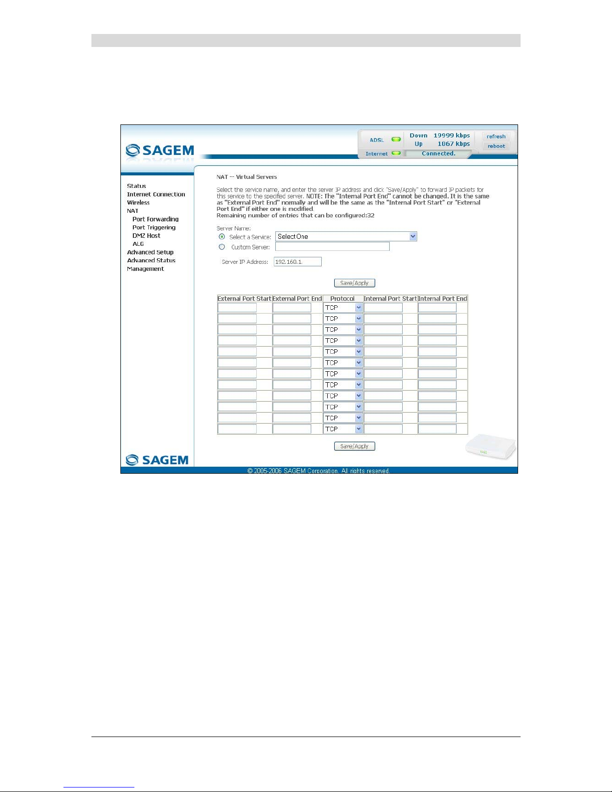
5.8.1 Port forwarding
Object: This menu is used to route directly to the External Ports the incoming data from a
Service server (such as, for example, FTP Server, SNMP, TFTP etc.) of the remote
network (WAN) to computers on the local network (LAN) via the Internal Ports.
• Select the Port forwarding menu in the NAT section to display the following screen:
Page 79

5 - Information / Configuration
F@st™ 2804v2 Reference Manual - 253329475-A
Sagemcom document. Reproduction and disclosure prohibited Page 5-43
Field Meaning
Server Name
Select a Service
Service available over Internet (such as, for example FTP Server,
SNMP, TFTP etc.).
Custom Server
Name you want to allocate to a local server.
External Port Start
Internal start port (WAN side).
External Port End
Internal end port (WAN side).
Protocol
Transport protocol (TCP, UDP or TCP/UDP).
Internal Port Start
Internal start port (LAN side).
Internal Port End
This internal end port (LAN side) is associated with the external
end port (WAN) side.
Note: This cannot be modified.
Server IP Address
Computer address delivered by your router's DHCP server.
Page 80
5 - Information / Configuration
F@st™ 2804v2 Reference Manual - 253329475-A
Page 5-44 Sagemcom document. Reproduction and disclosure prohibited
Add
• Click on the Add button; the following screen appears:
Page 81

5 - Information / Configuration
F@st™ 2804v2 Reference Manual - 253329475-A
Sagemcom document. Reproduction and disclosure prohibited Page 5-45
Proceed as follows:
¾ Check the "Select a Service" box, then select the service of your choice from the scroll
down list, for example "SNMP".
The "External Port Start", "External Port End", "Internal Port Start", "Internal Port End"
and Protocol fields (transport protocol associated with this service) are automatically filled
in the table.
Note: You may complete the table by adding other ports associated with a protocol.
or
¾ Check the "Custom Server" box, enter the name of the serve r you want to connect to, then:
• Complete the ID Host of your computer's IP address (this is attributed by your router's
DHCP server).
• Fill in the "External Port Start", "External Port End", "Internal Port Start",
"Internal Port End" and "Protocol" fields.
A few rules for entering values:
¾ When you want to select a single port, the start port ("External Port Start" or "Internal
Port Start") and the end port ("External Port End" or "Internal Port End") must be
identical.
¾ When you want to select a range of ports, the start port number must be lower than
the end port number.
¾ You must always start entering with the "External Port Start" and "External Port End"
ports,
¾ When you allocate a number to an "External Port Start", the same number is
automatically allocated to the "Internal Port Start" and identically for
"External Port End",
Page 82

5 - Information / Configuration
F@st™ 2804v2 Reference Manual - 253329475-A
Page 5-46 Sagemcom document. Reproduction and disclosure prohibited
The following diagram contains an example:
The "Delta Force 2" service is available on your computer via the external ports 3568 and 3569
(WAN side) and via the internal ports 3568 and 3569 (LAN side).
Page 83
5 - Information / Configuration
F@st™ 2804v2 Reference Manual - 253329475-A
Sagemcom document. Reproduction and disclosure prohibited Page 5-47
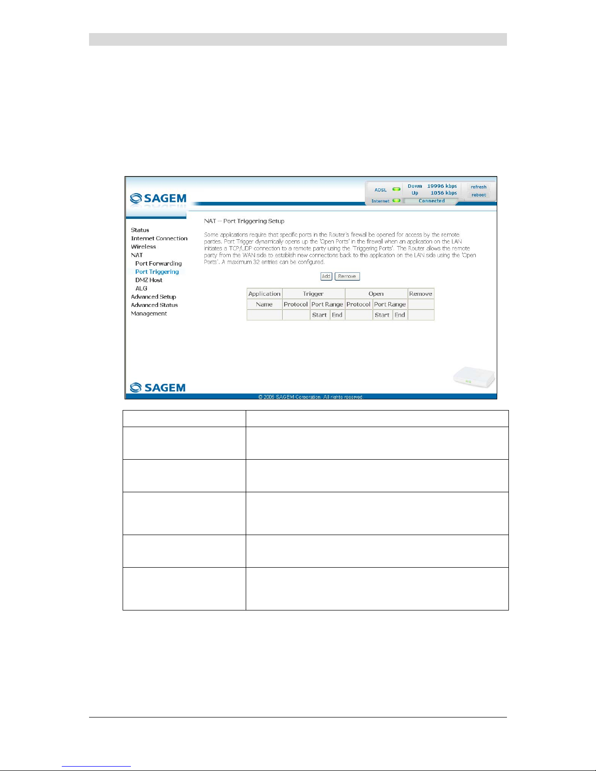
5.8.2 Port Triggering
Object: The purpose of this menu is to open dynamically the firewall ports (open ports) via
"Trigger Ports" when an application (such as games or video) opens a connection via
the transport layer (TCP or UDP).
• Select the Port Triggering menu in the NAT sect ion to display the following screen:
Field Meaning
Application
Name
Application name
Trigger
Protocol
Transport protocol (TCP, UDP or TCP/UDP).
Port Range
A port range contains a Start port and an End port.
Note: A single port is characterised by an identical start port
and end port.
Open
Protocol
Transport protocol (TCP, UDP or TCP/UDP).
Port Range
A port range contains a Start port and an End port.
Note: A single port is characterised by an identical start port
and end port.
Page 84

5 - Information / Configuration
F@st™ 2804v2 Reference Manual - 253329475-A
Page 5-48 Sagemcom document. Reproduction and disclosure prohibited
Add
• Click on the Add button; the following screen appears:
To configure "Trigger Port" and "Open Port", proceed as follows:
¾ Check the "Select an application" box, then select the service of your choice from the
scroll down list, for example "Aim Talk".
The "Trigger Port Start", "Trigger Port End", "Trigger Port Start", "Trigger Port End"
and Protocol fields (transport protocol associated with this service) are automatically filled
in the table.
Note: You may complete the table by adding other ports associated with a protocol.
or
¾ Check the "Custom Server" box then enter the name of the server you want to connect to,
then:
• Complete the ID Host of your computer's IP address (this is attributed by your router's
DHCP server).
• Fill in the "Trigger Port Start", "Trigger Port End", "Trigger Port Start",
"Trigger Port End" and "Protocol" fields.
Page 85

5 - Information / Configuration
F@st™ 2804v2 Reference Manual - 253329475-A
Sagemcom document. Reproduction and disclosure prohibited Page 5-49
A few rules for entering values:
¾ When you want to select a single port, the start port ("Trigger Port Start" or "Open
Port Start") and the end port ("Trigger Port End" or "Open Port End") must be
identical.
¾ When you want to select a range of ports, the start port number must be lower than
the end port number.
The following diagram contains an example:
Using the "Trigger" 3568 port (WAN side), the "Delta Force" service server triggers the opening
of port range 3100 to 3999 for your computer to access this service.
Page 86
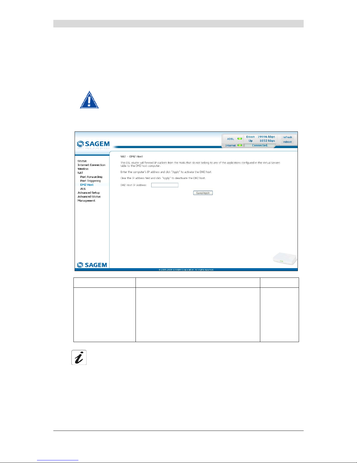
5 - Information / Configuration
F@st™ 2804v2 Reference Manual - 253329475-A
Page 5-50 Sagemcom document. Reproduction and disclosure prohibited
5.8.3 DMZ Host
Object: This "DMZ" (DeMilitarized Zone) lets you access the server you selected directly via
the Internet without going through the "Firewall".
Caution, this process presents an intrusion risk. It is therefore vital that
you take precautions so that no connections may be initiated to the private
network.
• Select the DMZ Host menu in the NAT section to display the following screen:
Field Action Default
DMZ Host IP Address
Enter the IP address of a server to activate the
"DMZ" and therefore access it directly from the
Internet.
To deactivate the "DMZ" zone, erase the address
entered in the field.
Note: Click on the Save/Apply button to take
account of the address or its erasure.
Empty
The "DMZ" zone is deactivated by default.
Page 87

5 - Information / Configuration
F@st™ 2804v2 Reference Manual - 253329475-A
Sagemcom document. Reproduction and disclosure prohibited Page 5-51
5.8.4 ALG
Object: The ALG (Application Layer Gateway) service is used to take charge of the SIP
protocol via the Wi-Fi or Ethernet interfaces in the telephony over IP (VoIP)
context.
• Select the ALG menu in the NAT se ction to display the following screen:
Field Meaning Default
SIP Enabled
Check the box to permit telephoning in VoIP via the
Wi-Fi or Ethernet interfaces using the SIP protocol.
Checked
Page 88

5 - Information / Configuration
F@st™ 2804v2 Reference Manual - 253329475-A
Page 5-52 Sagemcom document. Reproduction and disclosure prohibited
5.9 Advanced Setup
Object: This menu is used to configure the specific parameters for your router.
This menu must only be used by experienced users.
This section contains the following nine menus:
• WAN (see subsection 5.9.1),
• LAN (see subsection 5.9.2),
• Security (see subsection 5.9.3),
• Quality of Service (see subsection 5.9.4)(see note),
• Routing see subsection 5.9.5),
• DNS (see subsection 5.9.6),
• DSL (see subsection 5.9.7),
• Port Mapping (see subsection 5.9.8),
• Certificate (see subsection 5.9.9).
Note: This menu only appears if you checked the "Enable Quality Of Service" box in the
WAN interface configuration screen (see Advanced Setup/WAN –
subsection 5.9.1/Add).
5.9.1 WAN
Object: This menu is associated with the remote network. It is used to display the list of all the
configured PVCs, to add PVCs or remove them.
• Select the WAN menu in the Advanced Setup section to display the following screen:
Page 89

5 - Information / Configuration
F@st™ 2804v2 Reference Manual - 253329475-A
Sagemcom document. Reproduction and disclosure prohibited Page 5-53
Field Meaning
VPI/VCI
PVC identifier to configure.
Con. ID
Connection Identification. This is used to identify the different
PPP connections which belong to the same PVC. To do so,
you need only increment the "VC number" in the "Service" field
when adding a new "PVC".
Category
ATM type of service
Service
Name of the ATM service. This name is made up as follows:
Protocol_VPI_VCI_Index
For example: pppoe_0_35_1.
Interface
Name, allocated automatically, associated with the service
name (for example, ATM interface "ppp_0_35_1" associated
with the ATM service pppoe_0_35_1).
Protocol
Data flow encapsulation mode.
Igmp
Status (Enabled or Disabled) of the IGMP function. (see Note).
QoS
Status (Enabled or Disabled) of the Quality of Service (QoS).
State
Status (Enabled or Disabled) of the WAN interface.
Note: This function enables the distribution of Multicast datagrams over the local network
(LAN) and interaction between the router and the local network hosts.
Add
• Click on the Add button to display the following screen:
Page 90

5 - Information / Configuration
F@st™ 2804v2 Reference Manual - 253329475-A
Page 5-54 Sagemcom document. Reproduction and disclosure prohibited
ATM PVC Configuration
Field Action Default
VPI
Enter a VPI value
1
between 0 and 255.
0
VCI
Enter a VPI value
1
between 32 and 65535.
35
Service Category
Select the type of service adapter to the traffic
from the scroll down list:
UBR without PCR : Unspecified Bit Rate
UBR with PCR : Unspecified Bit Rate
CBR : Constant Bit Rate
Non Realtime VBR : Variable Bit Rate
Realtime VBR : Variable Bit Rate
UBR
without
PCR
Peak Cell Rate2 Enter a maximum number of cells transmitted
per second, between 1 and 2491.
0
Sustainable Cell Rate3 Enter an average number of cells transmitted
per second.
Note: This number must be lower than the
Peak Cell Rate (PCR).
0
Maximum Burst Size3 Enter the maximum number of cells emitted in
burst (value between 1 and 1000 000).
0
Enable Quality Of Service
Field Action Default
Enable Quality Of Service
Check the box to activate the quality of
service and display the new "Quality of
Service" menu in the Advanced Setup
section.
Not checked
1
This value is delivered to you by your Internet Service Provider (ISP).
2
This field only appears when the "UBR with PCR", "CBR", "Non Realtime VBR" or "Realtime VBR" type of
service is selected.
3
This file only appears when the "Non Realtime VBR" or "Realtime VBR" type of service is selected.
Page 91

5 - Information / Configuration
F@st™ 2804v2 Reference Manual - 253329475-A
Sagemcom document. Reproduction and disclosure prohibited Page 5-55
• Click on the Next button to continue configuring the remote network (WAN) and display the
following screen:
Depending on the type of network protocol selected, the encapsulation modes
suggested in the scroll down list in the appropriate field are different.
Therefore, and to provide more clarity, a summary table will be presented
below for each type of protocol.
PPP over ATM (PPPoA)
Field Action Default
Encapsulation Mode
Select the encapsulation of your choice from the
scroll down list.
• VC/MUX,
• LLC/ENCAPSULATION.
VC/MUX
Page 92

5 - Information / Configuration
F@st™ 2804v2 Reference Manual - 253329475-A
Page 5-56 Sagemcom document. Reproduction and disclosure prohibited
PPP over Ethernet (PPPoE)
Field Action Default
Encapsulation Mode
Select the encapsulation of your choice from the
scroll down list.
• LLC/SNAP-BRIDGING,
• VC/MUX.
LLC/SNAP-
BRIDGING
MAC Encapsulation Routing (MER)
Field Action Default
Encapsulation Mode
Select the encapsulation of your choice from the
scroll down list.
• LLC/SNAP-BRIDGING,
• VC/MUX.
LLC/SNAP-
BRIDGING
IP over ATM (IPoA)
Field Action Default
Encapsulation Mode
Select the encapsulation of your choice from the
scroll down list.
• LLC/SNAP-ROUTING,
• VC/MUX.
LLC/SNAP-
ROUTING
Bridging
Field Action Default
Encapsulation Mode
Select the encapsulation of your choice from the
scroll down list.
• LLC/SNAP-BRIDGING,
• VC/MUX.
LLC/SNAP-
BRIDGING
PPPoE/PPPoA
The encapsulation mode field will be selected automatically with PPPoE/PPPoA
protocol type.
Page 93
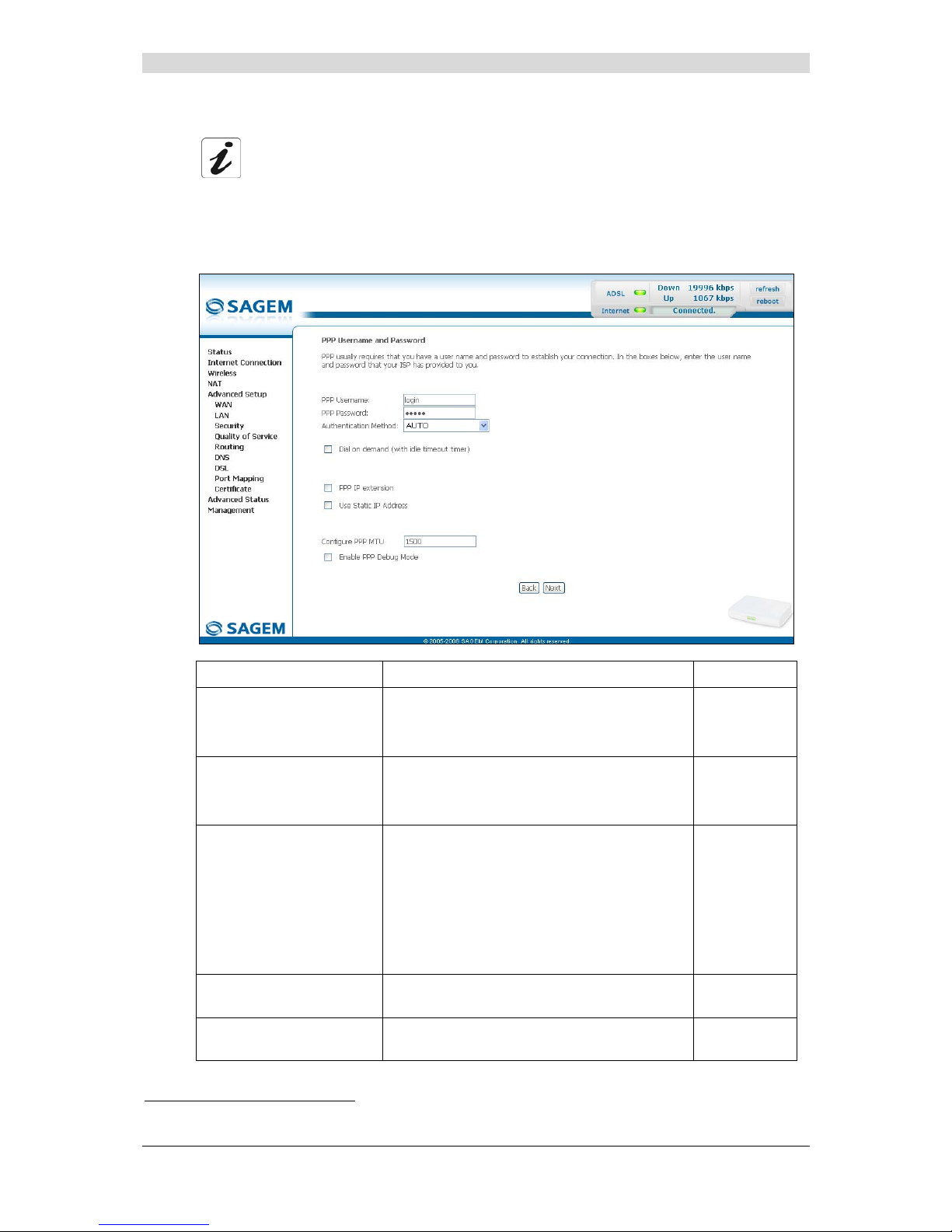
5 - Information / Configuration
F@st™ 2804v2 Reference Manual - 253329475-A
Sagemcom document. Reproduction and disclosure prohibited Page 5-57
• Click on the Next button to continue configuring the remote network (WAN).
Depending on the type of network protocol (PPPoA, PPPoE, MER, IPoA or Bridging)
selected earlier, the content of the following WAN interface configuration screens
differs.
Therefore, and for more clarity, each type of protocol will be dealt with
separately (screens + associated summary tables) below.
PPP over ATM (PPPoA)
Field Action Default
PPP Username
Enter your connection ID.
This information is provided to you by your
Internet Service Provider (ISP).
Empty
PPP Password
Enter your connection password.
This information is provided to you by your
Internet Service Provider (ISP).
Empty
Authentification Method
Select the authentication method of your
choice from the scroll down list:
• AUTO,
• PAP,
• CHAP,
• MSCHAP.
AUTO
Dial on demand
(with idle timeout timer)
Check the box to connect to Internet only for
"Traffic" on the ADSL line.
Not checked
Inactivity Timeout
(minutes) [1-4320]:
4
Enter a value (in minutes) between 1 and
4320 (i.e. 72 hours).
0
4
This field only appears when the "Dial on demand (with idle timeout timer)" field is activated (box checked).
Page 94

5 - Information / Configuration
F@st™ 2804v2 Reference Manual - 253329475-A
Page 5-58 Sagemcom document. Reproduction and disclosure prohibited
Field Action Default
PPP IP extension
Check the box to allocate your computer the
public address obtained from the DHCP
server of your Internet Service Provider (ISP).
Your router will then act as a bridge between
the server and your computer.
Not checked
Use Static IP Address
Check the box to use the static IP address.
Not checked
IP Address:5 Enter the static IP address
0.0.0.0
Configure PPP MTU
Enter an MTU (Maximum Transfer Unit) value
between 38 and 1492 (see Note).
1492
Enable PPP Debug mode
Check the box to use the PPP Debug mode.
In the event of connection failure, this option
will enable you to trace a possible problem in
the SYSLOG file.
Box
Not checked
Note: The MTU specifies the maximum size of the data used for packets expressed as a
number of bytes.
• Click on the Next button to continue configuring the remote network (WAN) in PPPoA
mode.
5
This field only appears when the "Use Static IP Address" field is activated (box checked).
Page 95

5 - Information / Configuration
F@st™ 2804v2 Reference Manual - 253329475-A
Sagemcom document. Reproduction and disclosure prohibited Page 5-59
Field Action Default
Enable NAT
Check the box to activate the NAT
function.
Checked
Enable Firewall
Check the box to activate the Firewall
service.
Checked
Enable IGMP Multicast
Check the box to activate the IGMP
function.
Not checked
Enable WAN Service
Check the box to activate the remote
network service (WAN).
See the note of information below.
Checked
Service Name
Displays the name of the service being
configured. This name, which is allocated
automatically, is made up as follows:
Protocol_VPI_VCI_Index
For example: pppoa_0_35_1.
Note: You may enter another service
name.
pppoa_0_35_1
The “Enable WAN Service” function makes it possible to disable connection types in
a list to use only the selected connection type. The "WAN" menu of the
"Advanced Status" section shows the "State is disable" if “Enable WAN Service”
has not been selected.
• Click on the Next button to continue configuring the remote network (WAN) in PPPoA
mode.
Page 96

5 - Information / Configuration
F@st™ 2804v2 Reference Manual - 253329475-A
Page 5-60 Sagemcom document. Reproduction and disclosure prohibited
Field Action
VPI/VCI
Displays the VPI/VCI specific to the "PPPoA" connection
Connection Type
Displays the "PPPoA" protocol
Service Name
Displays the name of the service: pppoa_0_35_1
Service Category
Displays the type of service adapted to the traffic required.
IP Address
Indicates that the IP address is allocated automatically:
Automaticaly Assigned
Service State
Displays the status of the service: Enabled
NAT
Displays the status of the NAT: Enabled
Firewall
Displays the status of the firewall: Enabled
IGMP Multicast
Displays the status of the IGMP function: Disabled
Page 97

5 - Information / Configuration
F@st™ 2804v2 Reference Manual - 253329475-A
Sagemcom document. Reproduction and disclosure prohibited Page 5-61
PPP over Ethernet (PPPoE)
Field Action Default
PPP Username
Enter your connection ID.
This information is provided to you by your
Internet Service Provider (ISP).
Empty
PPP Password
Enter your connection password.
This information is provided to you by your
Internet Service Provider (ISP).
Empty
PPPoE Service Name
Enter the name of the PPPoE service.
This information is provided to you by your
Internet Service Provider (ISP).
Empty
Authentification Method
Select the authentication method of your
choice from the scroll down list:
• AUTO,
• PAP,
• CHAP,
• MSCHAP.
AUTO
Dial on demand
(with idle timeout timer)
Check the box to only connect to the Internet
on "Traffic".
_
Inactivity Timeout
(minutes) [1-4320]:
4
Enter the inactivity time. This value (in
minutes) is between 1 and 4320
(i.e. 72 hours).
If there is no traffic for a certain period of time,
the PPPoE session is interrupted.
0
Page 98
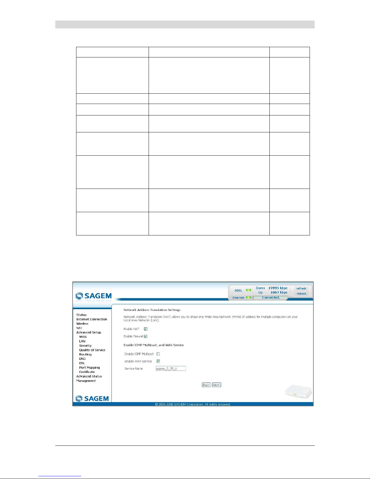
5 - Information / Configuration
F@st™ 2804v2 Reference Manual - 253329475-A
Page 5-62 Sagemcom document. Reproduction and disclosure prohibited
Field Action Default
PPP IP extension
Check the box to allocate the public address
obtained from the DHCP server of your
Internet Service Provider (ISP) to your
computer. Your router will then act as a bridge
between the server and your computer.
_
Use Static IP Address
Check the box to use the static IP address.
_
IP Address:5
Enter the static IP address.
0.0.0.0
Retry PPP password on
authentication error
Check the box, PPP can be retried again and
again while authentication fails
Box
Not checked
Configure PPP MTU
Enter an MTU (Maximum Transfer Unit) value.
This value (in bytes) is between 38 and 1492
(see Note).
1492
Enable PPP Debug mode
Check the box to use the PPP Debug mode.
In the event of connection failure, this option
will enable you to trace a possible problem in
the SYSLOG file.
Box
Not checked
Bridge PPPoE frames
between WAN and local
ports
Check the box to enable the router when
bridging the frames between WAN and local
Ethernet ports
Checked
Only Bridge PPPoE
Frames
Check the box to filter out all the non-PPPoE
packets when bridging the frames between
WAN and local ports.
Checked
Note: The MTU specifies the maximum size of the data used (IP packets) expressed as a
number of bytes.
• Click on the Next button to continue configuring the remote network (WAN) in PPPoE
mode.
Page 99
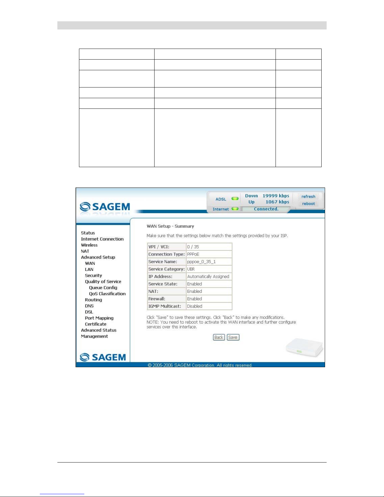
5 - Information / Configuration
F@st™ 2804v2 Reference Manual - 253329475-A
Sagemcom document. Reproduction and disclosure prohibited Page 5-63
Field Action Default
Enable NAT
Check the box to activate the NAT function.
Checked
Enable Firewall
Check the box to activate the Firewall
service.
Checked
Enable IGMP Multicast
Check the box to activate the IGMP function.
Not checked
Enable WAN Service
Check the box to activate the WAN service.
Checked
Service Name
Displays the name of the service being
configured. This name, which is allocated
automatically, is made up as follows:
Protocol_VPI_VCI_Index
For example: pppoe_0_35_1.
Note: You may enter another service
name.
pppoe_0_35_1
Click on the Next button to continue configuring the remote network (WAN) in PPPoE mode.
Page 100

5 - Information / Configuration
F@st™ 2804v2 Reference Manual - 253329475-A
Page 5-64 Sagemcom document. Reproduction and disclosure prohibited
Field Action
VPI/VCI
Displays the VPI/VCI specific to the "PPPoE" connection
Connection Type
Displays the "PPPoE" protocol
Service Name
Displays the name of the service: pppoe_0_35_1
Service Category
Displays the type of service adapted to the traffic required.
IP Address
Indicates that the IP address is allocated automatically:
Automaticaly Assigned
Service State
Displays the status of the service: Enabled
NAT
Displays the status of the NAT: Enabled
Firewall
Displays the status of the firewall: Enabled
IGMP Multicast
Displays the status of the IGMP function: Disabled
 Loading...