

Page 1

HiLoNC 3GPS Interface Board User
Guide
URD1 OTL 5696.1-025 72772 ed 01
HiLoNC 3GPS Interface Board user guide
22/09/2011
Page 2

Table of Content
1. Revision History
2. Function description of all key components
3. Jumpers setting
External document | URD1 OTL 5696.1-025 72772 ed 01 | 22 September 2011
This document and the information contained are Sagemcom property and shall not be copied or disclosed to any third party without Sagemcom prior written authorization
2
Page 3
1 Revision History
Revision Description Date
V1 First draft release Sept 22 2011
Note: This User guide may also refer the HiAllNC, a 2G automotive M2M module with e-Call capabilities
compliant in its early version (until sample version B1) with this Interface board.
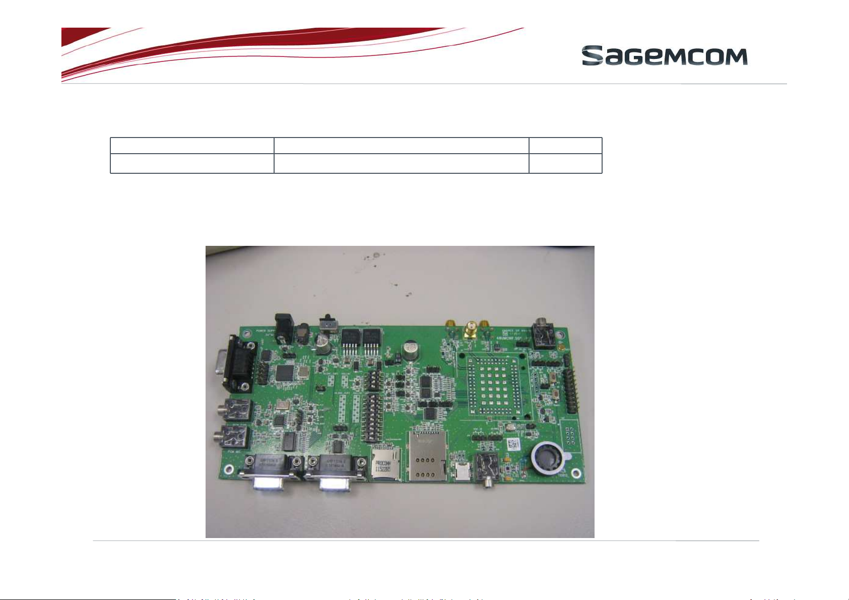
2 Function description of all key components
External document | URD1 OTL 5696.1-025 72772 ed 01 | 22 September 2011
This document and the information contained are Sagemcom property and shall not be copied or disclosed to any third party without Sagemcom prior written authorization
3
Page 4
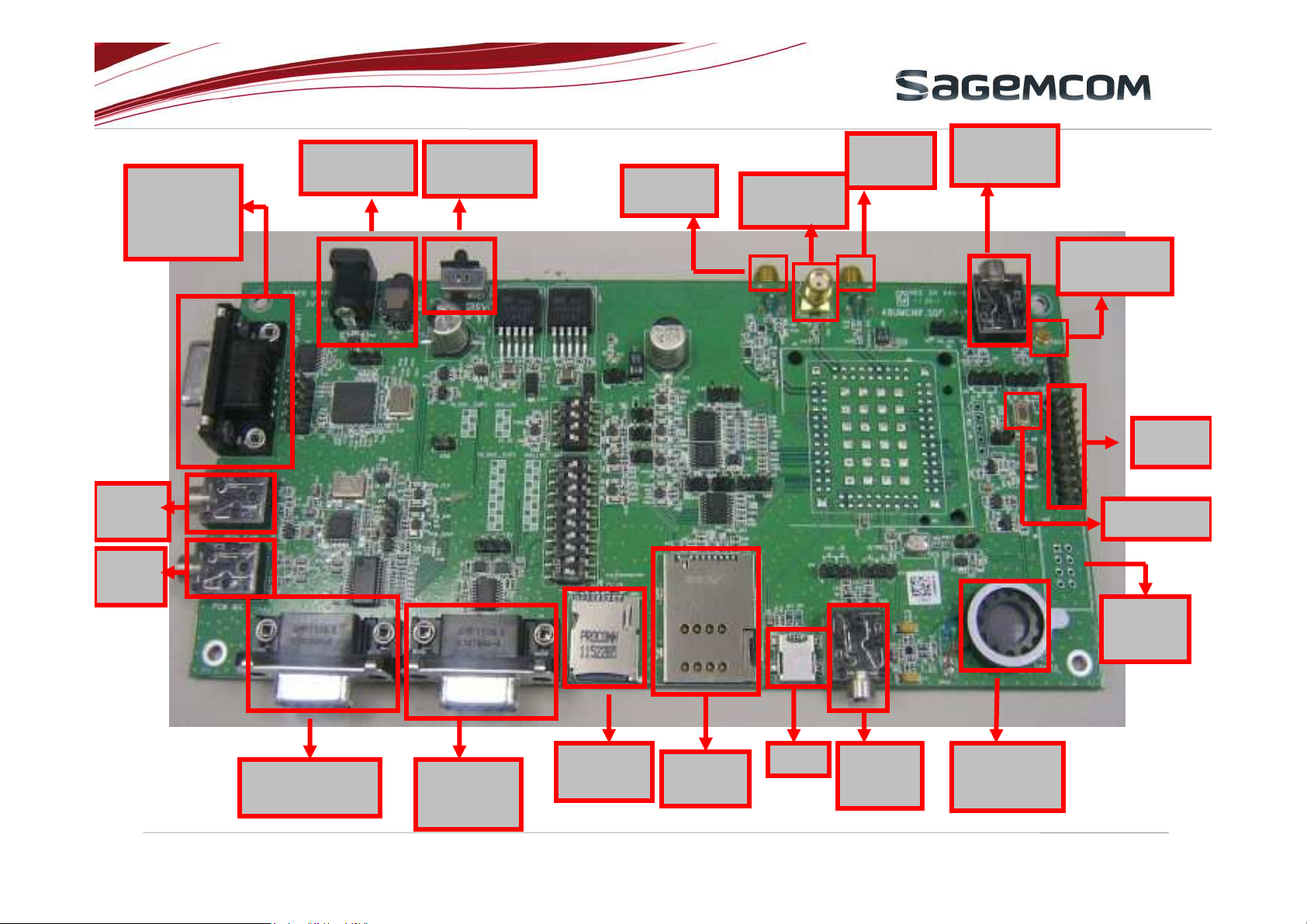
UART for
micro
processor
PCM
CODEC
output
PCM
CODE
C input
DC jack
5V~16V in
DC power
switch
GPS
Ant. in
Diversity
RF in.
Primar
y RF in
Audio in
(Cable)
Audio in
(Mic
)
Power key
SPI
HE10
Conn.
JTAG
Conn
.
USB
RS232 for
HiLoNC3GPS
RS232
for
T-Flash
card
USIM
socket
HIALLNC
External document | URD1 OTL 5696.1-025 72772 ed 01 | 22 September 2011
This document and the information contained are Sagemcom property and shall not be copied or disclosed to any third party without Sagemcom prior written authorization
Audio
output
(cable)
Audio
output
(Speaker)
4
Page 5
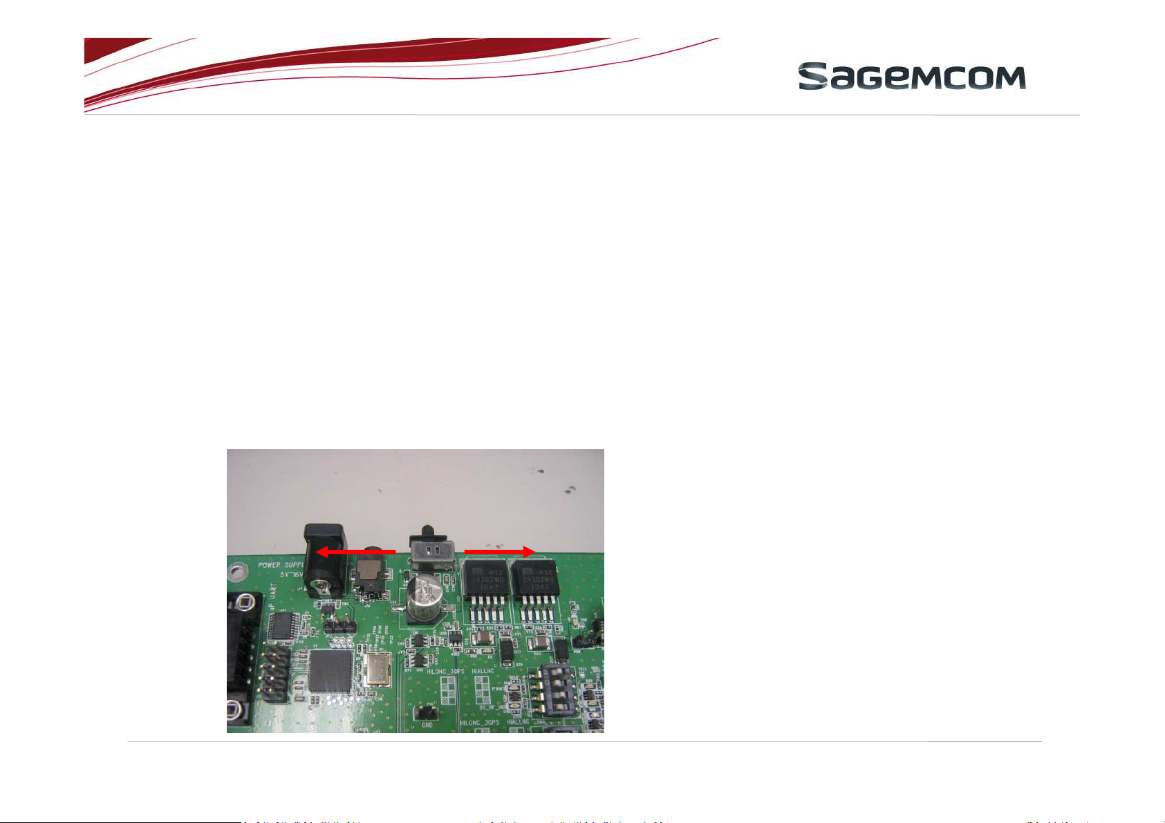
a. DC jack
The adapter must be in the range 5V~16V and can supply over 1.5A.
b. DC power switch
Switch to right direction to power on HiLoNC3GPS module and other function on the
interface board.
Otherwise, switch to left direction to power off all power including module and
interface board.
RightLeft
External document | URD1 OTL 5696.1-025 72772 ed 01 | 22 September 2011
This document and the information contained are Sagemcom property and shall not be copied or disclosed to any third party without Sagemcom prior written authorization
5
Page 6

c. Primary RF in
This is for the purpose of connecting interface board and base station (ex: CMU200,
8960, real antenna)
d. Diversity RF in
This is for the purpose of connecting interface board and base station (ex: CMU200,
8960, real antenna)
e. GPS Antenna in
This is for the purpose of connecting interface board and satellite.
f. USB
This USB has two main function:
download firmware
send AT command
External document | URD1 OTL 5696.1-025 72772 ed 01 | 22 September 2011
This document and the information contained are Sagemcom property and shall not be copied or disclosed to any third party without Sagemcom prior written authorization
6
Page 7

g. Audio in (cable)
HiLoNC3GPS does not support analog audio. So this audio jack is not used for
HiLoNC3GPS .
For HIALLNC module, this path connected to the microphone signal. The audio
generator can output a tone to HIALLNC module through this jack.
h. Audio in (Mic)
The purpose is the same as item “g” and we can switch the audio path by different
location of jumps (JP4/JP6).
i. Power key
Press this key to power on/off HiLoNC3GPS. For the new version of interface board , In
case of shorting the jump (location P8) , the module will power on automatically.
j. Audio output (Cable)
This audio jack is used only for HIALLNC module.
External document | URD1 OTL 5696.1-025 72772 ed 01 | 22 September 2011
This document and the information contained are Sagemcom property and shall not be copied or disclosed to any third party without Sagemcom prior written authorization
7
Page 8

k. Audio output (Speaker)
The purpose is the same as item “j” and we can switch the audio path by different
location of jumps (JP7/JP8).
l. USIM socket
The purpose is to Insert SIM card.
m. RS232 for HiLoNC3GPS
This is a full function of RS232 standard including TX/RX/CTS/RTS/DCD/DSR/DTR/RI
from HiLoNC3GPS. Use a straight (none cross) RS232 cable to connect it.
Another, the indicator LEDs on the interface board show the signals are active or
not.(light means active)
n. RS232 for HIALLNC
This DSUB-9 connector is used only for HIALLNC module.
o. UART for micro processor
This UART is reserved to control micro processor.
External document | URD1 OTL 5696.1-025 72772 ed 01 | 22 September 2011
This document and the information contained are Sagemcom property and shall not be copied or disclosed to any third party without Sagemcom prior written authorization
8
Page 9

p. PCM CODEC output
HiLoNC3GPS PCM signals are decoded by PCM CODEC(TLV320AIC1110) and output
from this audio jack.
q. PCM CODEC input
Analog audio pass through this jack and encoded by PCM CODEC(TLV320AIC1110).
r. T-Flash socket
This is a T-Flash card socket with SDIO interface.
s. SPI HE10 connector
This connector is used for HIALLNC software trace.
External document | URD1 OTL 5696.1-025 72772 ed 01 | 22 September 2011
This document and the information contained are Sagemcom property and shall not be copied or disclosed to any third party without Sagemcom prior written authorization
9
Page 10

3. JUMP setting
3.1 3.7V power for HiLoNC3GPS module:
Short this jump (location P26) to supply module 3.7V. If remove this jump , all device
will be turned on beside module.
External document | URD1 OTL 5696.1-025 72772 ed 01 | 22 September 2011
This document and the information contained are Sagemcom property and shall not be copied or disclosed to any third party without Sagemcom prior written authorization
10
Page 11
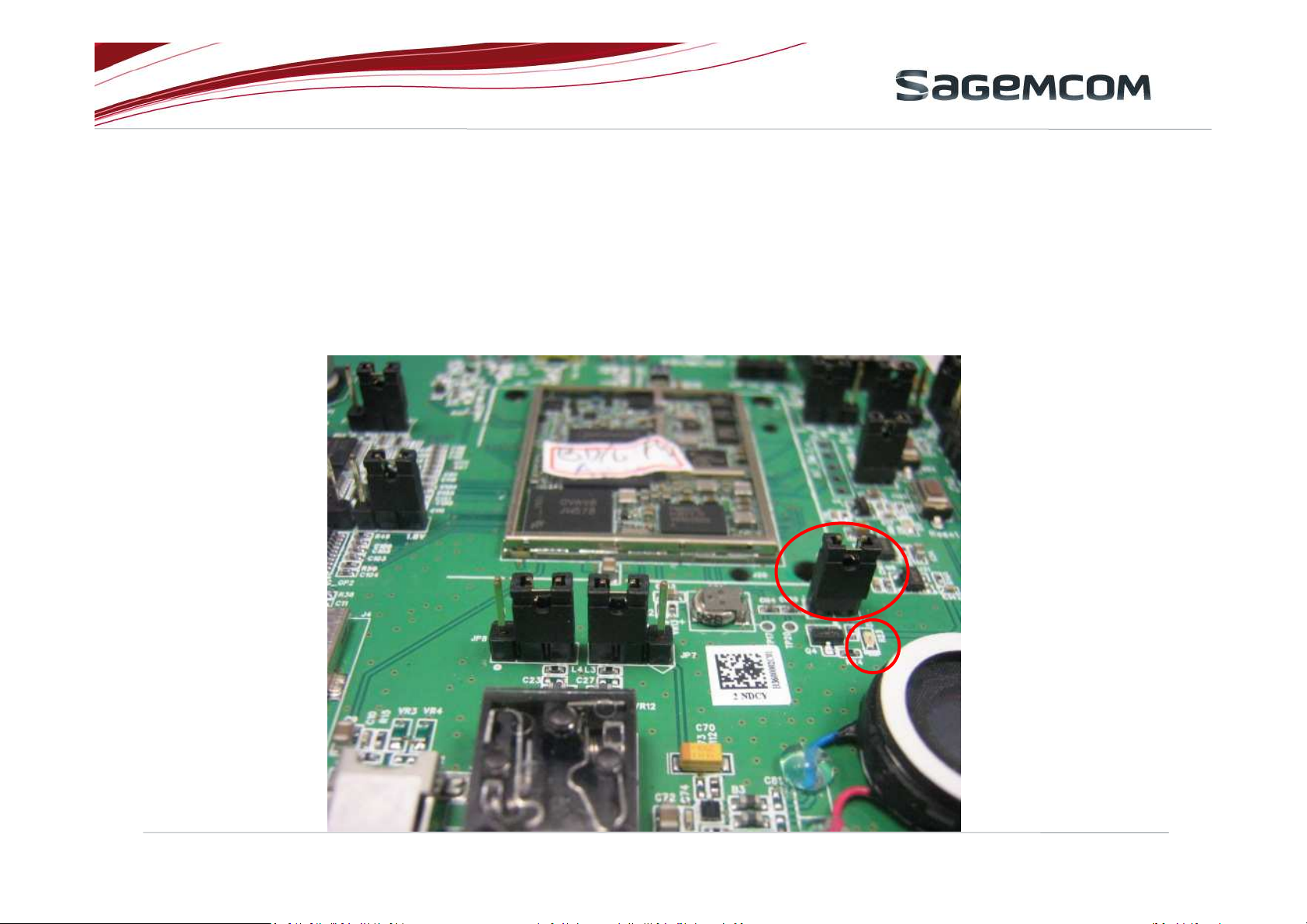
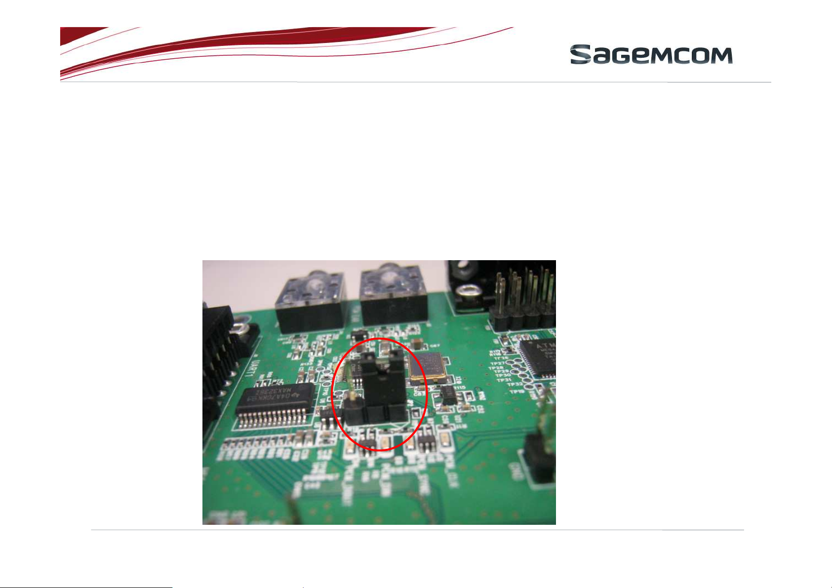
3.2 VGPIO indictor
If shorting this jump (location P12), the LED (location D7) will light when VGPIO output
2.85V.
External document | URD1 OTL 5696.1-025 72772 ed 01 | 22 September 2011
This document and the information contained are Sagemcom property and shall not be copied or disclosed to any third party without Sagemcom prior written authorization
11
Page 12

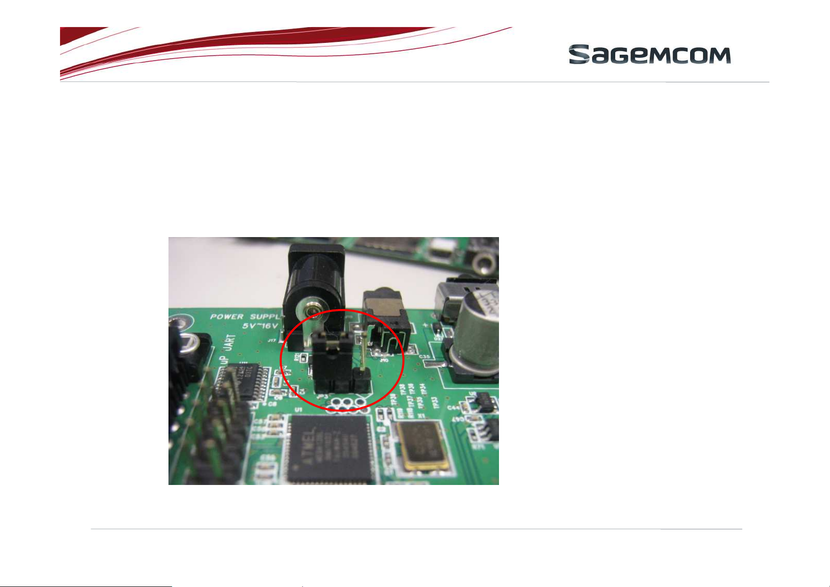
3.3 Power key
Short this jump (P8) will make module power on automatically after supplying 3.7V.
External document | URD1 OTL 5696.1-025 72772 ed 01 | 22 September 2011
This document and the information contained are Sagemcom property and shall not be copied or disclosed to any third party without Sagemcom prior written authorization
12
Page 13

3.4 Microphone signal
JP4.1 short to JP4.2 / JP6.2 short to JP6.3 Microphone input from J5
JP4.2 short to JP4.3 / JP6.1 short to JP6.2 Microphone input from MIC1
External document | URD1 OTL 5696.1-025 72772 ed 01 | 22 September 2011
This document and the information contained are Sagemcom property and shall not be copied or disclosed to any third party without Sagemcom prior written authorization
13
Page 14

3.5 Speaker signal
JP7.1 short to JP7.2 / JP8.1 short to JP8.2 Speaker output to Speaker
JP7.2 short to JP7.3 / JP8.2 short to JP8.3 Speaker output to J6
External document | URD1 OTL 5696.1-025 72772 ed 01 | 22 September 2011
This document and the information contained are Sagemcom property and shall not be copied or disclosed to any third party without Sagemcom prior written authorization
14
Page 15
3.6 Micro processor power
JP3.2 short to JP3.3 3Vin for Micro processor
JP3.1 short to JP3.2 3.7Vin for Micro processor
External document | URD1 OTL 5696.1-025 72772 ed 01 | 22 September 2011
This document and the information contained are Sagemcom property and shall not be copied or disclosed to any third party without Sagemcom prior written authorization
15
Page 16
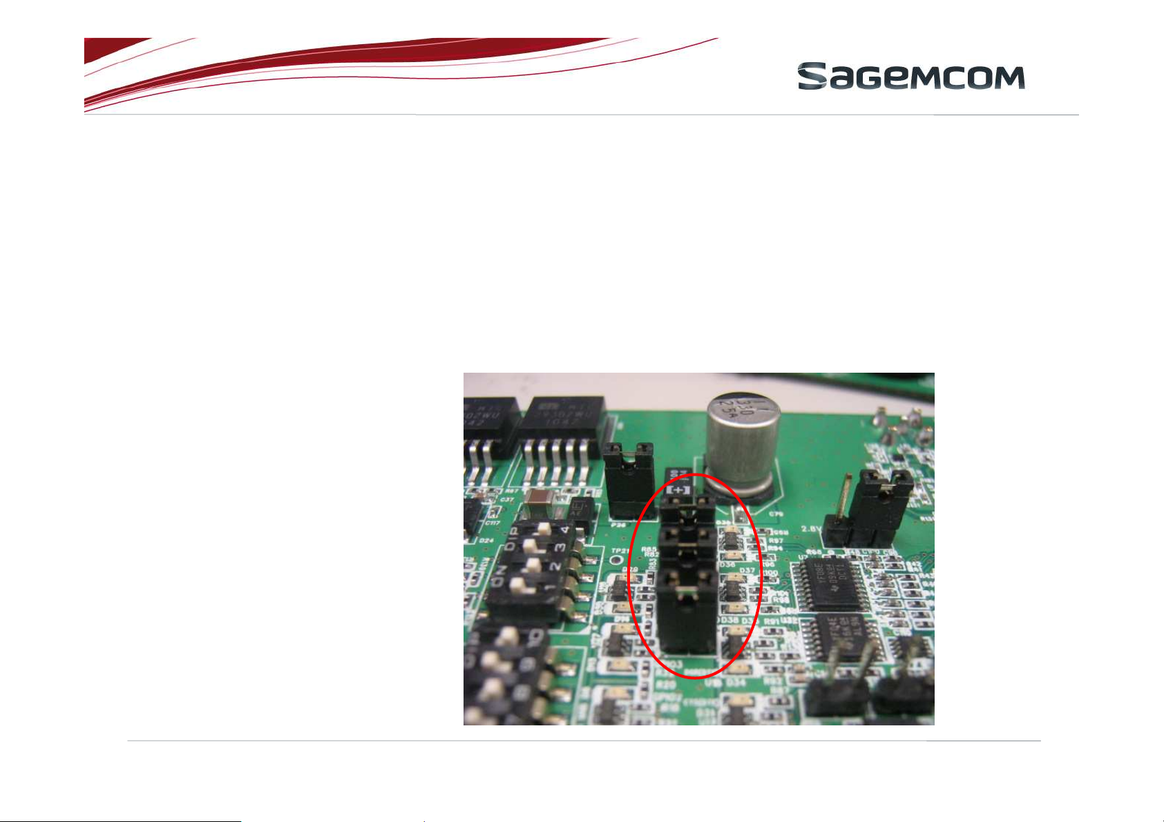
3.7 PCM CODEC
JP2.1 short to JP2.2 PCM CODEC power up in the default mode when power is
applied.
JP2.2 short to JP2.3 PCM CODEC goes to a power-down state when power is applied.
In this mode , an I2C interface is required to power up PCM
CODEC.
External document | URD1 OTL 5696.1-025 72772 ed 01 | 22 September 2011
This document and the information contained are Sagemcom property and shall not be copied or disclosed to any third party without Sagemcom prior written authorization
16
Page 17
3.8 GPIO4/GPIO5/GPIO6
P27 GPIO4. This is a jump that connect GPIO4 to LED indicator. Customer can
remove this jump for debug.
P30 GPIO5. This is a jump that connect GPIO5 to LED indicator. Customer can
remove this jump for debug.
P31 GPIO6. This is a jump that connect GPIO6 to LED indicator. Customer can
remove this jump for debug.
P31
P30
P27
External document | URD1 OTL 5696.1-025 72772 ed 01 | 22 September 2011
This document and the information contained are Sagemcom property and shall not be copied or disclosed to any third party without Sagemcom prior written authorization
17
Page 18
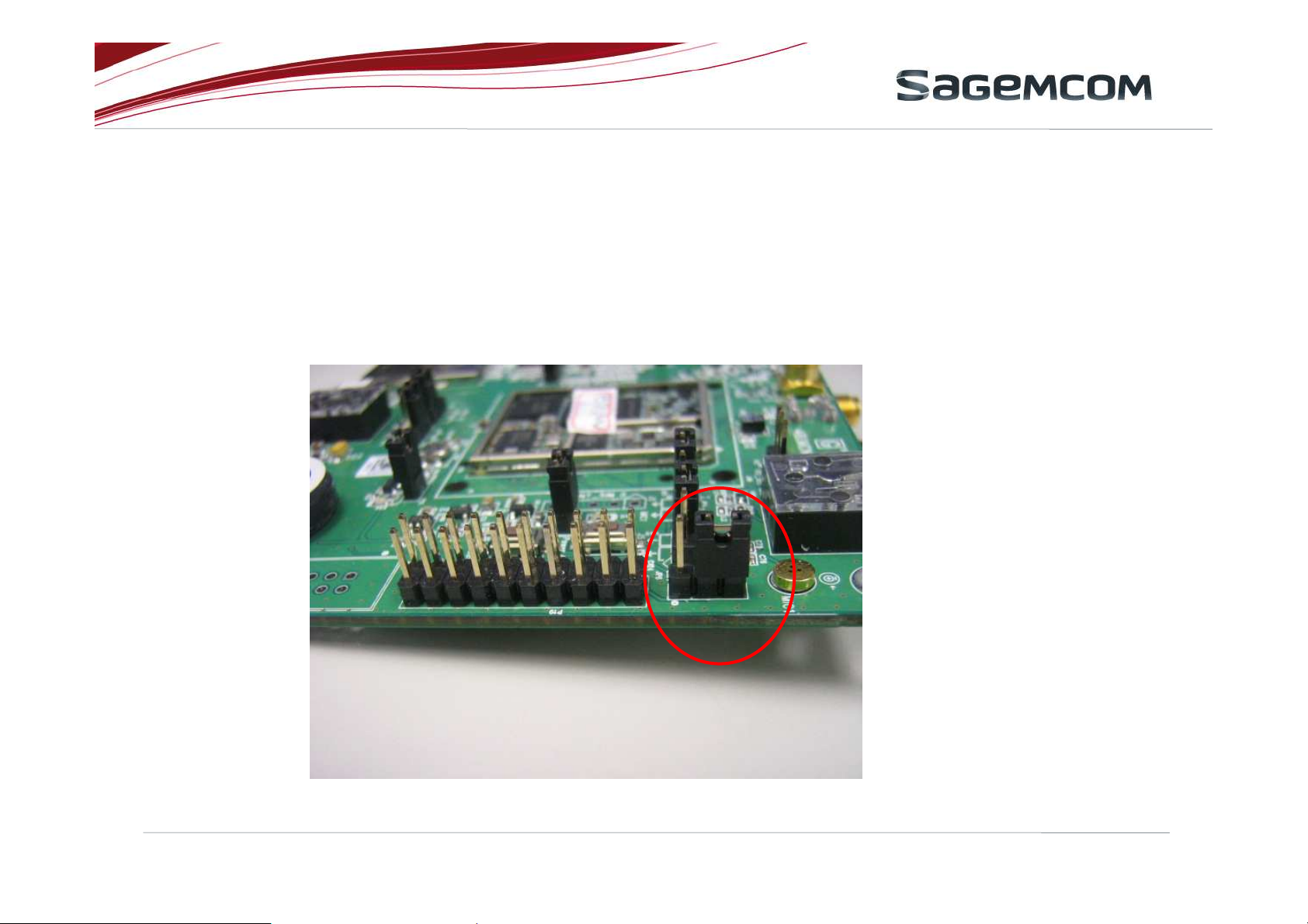
3.9 JTAG
JP13.1 short to JP13.2 2.8V power supply to JTAG.
JP13.2 short to JP13.3 1.8V power supply to JTAG (HiLoNC3GPS)
External document | URD1 OTL 5696.1-025 72772 ed 01 | 22 September 2011
This document and the information contained are Sagemcom property and shall not be copied or disclosed to any third party without Sagemcom prior written authorization
18
Page 19

3.10 VIO_SEL (for HIALLNC only)
JP5.1 short to JP5.2 VIO_SEL=HiZ .
JP5.2 short to JP5.3 VIO_SEL=0
External document | URD1 OTL 5696.1-025 72772 ed 01 | 22 September 2011
This document and the information contained are Sagemcom property and shall not be copied or disclosed to any third party without Sagemcom prior written authorization
19
Page 20

3.11 UART1 level shifter
JP10.1 short to JP10.2 Under the condition of HIALLNC VIO_SEL=HiZ , put the
jumps on JP10 pin1/2 to select 2.8V voltage supply.
JP10.2 short to JP10.3 put the jump on JP10 pin2/3 for HiLoNC3GPS.
JP11 For HiLoNC3GPS, keep JP11 open.
For HIALLNC (VIO_SEL=HiZ), keep JP11 open.
For HIALLNC (VIO_SEL=0), put jump on JP11.
JP12 For HiLoNC3GPS, keep JP12 open.
For HIALLNC (VIO_SEL=HiZ), keep JP12 open.
For HIALLNC (VIO_SEL=0), put jump on JP12.
External document | URD1 OTL 5696.1-025 72772 ed 01 | 22 September 2011
This document and the information contained are Sagemcom property and shall not be copied or disclosed to any third party without Sagemcom prior written authorization
20
Page 21

JP10
JP11 JP12
External document | URD1 OTL 5696.1-025 72772 ed 01 | 22 September 2011
This document and the information contained are Sagemcom property and shall not be copied or disclosed to any third party without Sagemcom prior written authorization
21
Page 22

3.12 UART0 level shifter (for HIALLNC RTC/CTS only)
JP14.1 short to JP14.2 Under the condition of HIALLNC VIO_SEL=HiZ , put the
jumps on JP14 pin1/2 to select level shifter 2.8V voltage
supply.
JP14.2 short to JP14.3 Under the condition of HIALLNC VIO_SEL=0 , put the
jumps on JP14 pin2/3 to select level shifter 1.8V voltage
supply.
Keep JP14 open for HiLoNC3GPS.
External document | URD1 OTL 5696.1-025 72772 ed 01 | 22 September 2011
This document and the information contained are Sagemcom property and shall not be copied or disclosed to any third party without Sagemcom prior written authorization
22
Page 23

3.13 PCM level shifter
JP9.1 short to JP9.2 Select 2.8V voltage level for PCM level shift. This setting is for
HIALLNC module.
JP10.2 short to JP10.3 Select 1.8V voltage level for PCM level shift. This setting is for
HiLoNC3GPS module.
External document | URD1 OTL 5696.1-025 72772 ed 01 | 22 September 2011
This document and the information contained are Sagemcom property and shall not be copied or disclosed to any third party without Sagemcom prior written authorization
23
Page 24

3.14 SDIO(HiLoNC3GPS)/UART0(HIALLNC)
SW5 Due to HiLoNC3GPS and HIALLNC share some pads but for different function,
SW5 configuration is mandatory.
The silkscreen on PCB also indicates the setting for HiLoNC3GPS and HIALLNC.
Below shows the HiLoNC3GPS setting.
External document | URD1 OTL 5696.1-025 72772 ed 01 | 22 September 2011
This document and the information contained are Sagemcom property and shall not be copied or disclosed to any third party without Sagemcom prior written authorization
24
Page 25

3.15 PWM & 2G_IND(HiLoNC3GPS)/ANT DIANOSTIC(HIALLNC)
SW6 Due to HiLoNC3GPS and HIALLNC share some pads but for different function,
SW6 configuration is mandatory.
The silkscreen on PCB also indicates the setting for HiLoNC3GPS and HIALLNC.
Below shows the HiLoNC3GPS setting.
External document | URD1 OTL 5696.1-025 72772 ed 01 | 22 September 2011
This document and the information contained are Sagemcom property and shall not be copied or disclosed to any third party without Sagemcom prior written authorization
25
 Loading...