

Page 1

COMPACT
155 Mbit/s
ADD-DROP
MULTIPLEXER
MULTIPLEXEUR ADD-DROP
à 155 Mbit/s COMPACT
ADR 155C
Installation and User Guide
Guide d'Installation et d'Utilisation
N56717020101
Issue : April 2000
Edition : Avril 2000
Page 2

Page 3

COMPACT
155 Mbit/s
ADD-DROP
MULTIPLEXER
MULTIPLEXEUR ADD-DROP
à 155 Mbit/s COMPACT
ADR 155C
Installation and User Guide
Guide d'Installation et d'Utilisation
N56717020101
Issue : April 2000
Edition : Avril 2000
Page 4

LIST OF CHANGES
REPERTOIRE DES MISES A JOUR
(A new edition replaces any previous versions)
(Une nouvelle édition annule et remplace la précédente)
No/
N°
0101 April 2000/
Remarque importante : La version logicielle actuelle n'offre pas la fonction RIP décrite dans ce
Important remark : The current software version does not offer the RIP function described
Date/
Date
Avril 2000
guide.
in this guide
Change description
mise à jour
Creation of original user guide/
Création du document à l'édition originale
/Description de la
Page
/Page
All pages/
Toutes pages
Page 5

COMPACT 155 Mbit/s
ADD-DROP MULTIPLEXER
ADR 155C
Installation and User Guide
Installation and User Guide - N56717020101
Reproduction and communication in any form prohibited without the written permission of
(
Page A0-1
Page 6

PORTS SECURITY LEVEL
Port safety level for the 19" subrack access
The connectors are identified on the front panels of the equipment (cards or motherboard).
Connectors Function
Security
level
PWRA/PWRB Power supply
PWR Power supply SELV
Motherboard
SYNC G.703 2 Mbit/s synchronization Ports SELV
E1 INPUT & E1 OUTPUT G.703 2 Mbit/s Ports SELV
MNGT Other equipment connection SELV
COMM VT100 local supervision SELV
ETH Ethernet LAN remote supervision SELV
LOOPS Loops and remote signaling SELV
ADR ICI 1.x Card
TR and REC G.957 and G.958 STM-1 IC1.1 or IC1.2 Optical Laser class 1
Dangerless
EOW and AUX Engineering Order Wire SELV
ADR LAN1 Card
ETH Ethernet Port SELV
ADR 21E120 Card
E1 INPUT & E1 OUTPUT G.703 2 Mbit/s Ports SELV
SELV
1
)
The 19" subrack must be mounted only in racks with a bottom part that is
closed or fitted with a class V1 or HF1 or better air filter, or that stand on a
non-flammable floor..
Safe earth requirement
This equipment m us t be ins talled only by skilled personnel. For compliance, the protective earth
terminal must be connected to a safe earth with an impedance Z of less than 5 Ohms.
)
Handling precaution: For any work to be carried out inside the equipment, an
antistatic wrist strap must be worn.
Lithium Battery
)
Warning : If the battery is incorrectly replaced there is a risk of explosion.
Only replace with same type battery or equivalent type recommanded by the
manufacturer
Dispose of used battery according to manufacturer instructions
In ADR155C, battery replacement may only be done by return Supply Support Department.
1
Safety Extra Low Voltage Circuit
Installation and User Guide - N56717020101
Page A0-2
Reproduction and communication in any form prohibited without the written permission of
(
Page 7

CONTENTS
CHANGE LIST 0-2
SECTION A : Installation and user guide...................... A0-1 to AA-6
PORTS SECURITY LEVEL A0-2
CONTENTS A0-3 to A0-4
1. INSTALLATION AND COMMISSIONING
1.1 - General A1-1
1.2 - Subrack
1.3 - Connecting ports A1-4
1.3.1 - Connecting Power Supply A1-4
1.3.2 - Connecting on motherboard
1.3.3 - Connecting on the ADR IC1.x card
1.3.4 - Connecting on ADR LAN1 card
1.3.5 -
1.3.6 - 75 Ω connecting strip A1-18
1.4 - Commissioning
1.4.1 - Configuration required A1-22
1.4.2 - Parameterizing the communication function A1-22
1.4.3 - Using HTTP navigator
Figure 1-1 ADR155C Subrack Installation A1-2
Figure 1-2 Connecting power supply ports A1-5
Figure 1-3 Connecting motherboard inputs A1-6
Figure 1-4 Connecting ADR IC1.x card inputs A1-12
Figure 1-5 Connecting ADR LAN1 card input A1-16
Figure 1-6 Connecting ADR 21E120 card input A1-17
Figure 1-7 75 Ω connecting strip A1-18
Figure 1-8 Commissioning procedure for ADR155C network A1-19
Figure 1-9 Examples of the communication function configuration A1-21
Figure 1-10 Menu structure A1-27
installation A1-3
Connecting on ADR 21E120 card
........................................................... A1-1 to A1-28
A1-7
A1-13
A1-16
A1-17
A1-20
A1-26
2. OPERATION......................................................................................................... A2-1 to A2-20
2.1 - Functional description A2-1
2.2 - General A2-2
2.3 - Operational parameters A2-2
2.4 - Predefined functions A2-9
2.5 - Alarms processing A2-12
2.6 - Performance processing A2-17
2.7 - Procedure for replacing subassemblies A2-19
Installation and User Guide - N56717020101
Reproduction and communication in any form prohibited without the written permission of
(
Page A0-3
Page 8

Figure 2-1 Synchronization from the 2 MHz external sync input (T3) A2-10
Figure 2-2 Synchronization from the 2 MHz port A2-10
Figure 2-3 Remote loopback function (registering alarms on central site) A2-11
Tables 2-1 to 2-6 Configuration parameters A2-2 to A2-7
Tables 2-7 to 2-8 Commands A2-8 to A2-9
Tables 2-9 to 2-10 Alarms and severity A2-13 to A2-14
3. SPARE PARTS....................................................................................................... A3-1 to A3-2
4. SPECIFICATIONS.................................................................................................. A4-1 to A4-2
ANNEX A - CONSTRUCTING AN IP NETWORK ADDRESSING PLAN AA-1 to AA-6
A.1 - Preamble AA-1
A.2 - Addressing IP AA-2
A.3 - Adressing plan AA-3
A.4 - Use of static tables AA-3
A.5 - Use of RIP routing demon AA-5
SECTION B : Guide d'installation et d'utilisation............ B0-1 à BA-6
Installation and User Guide - N56717020101
Page A0-4
Reproduction and communication in any form prohibited without the written permission of
(
Page 9

1 - INSTALLATION AND COMMISSIONING
1. INSTALLATION AND COMMISSIONING
1.1 - General
The ADR 155C is an optical STM-1 add-drop multiplexer used to build STM-1 point-to-point
links, STM-1 rings, or mesh networks with conduct (SNC) or line (MSP) protection, so
performing the conveyance of links at 2 Mbit/s, Ethernet, STM-1.
The ADR 155C can be used as:
STM-1 terminal multiplexer with maximum capacity of 63 VC12 and capability of 1+1
protection,
STM-1 repeater, capability of regenerating 2 VC4,
STM1 multiplexer with insertion/extraction, with maximum capacity of 4 STM-1 and
insertion/extraction of 21 VC12
LAN interconnection point (in exclusive function up to 3 remote links totalling 3 VC3 used).
This equipment is managed from a HTTP navigator:
either locally, via its dedicated Ethernet interface
or remotely by teleoperation
or from the IONOS- ANM network manager; in this last case, us ing the SNMP protocol also
allows global network supervision.
Using a local terminal with VT100 emulation is necessary on the first commissioning, for the
configuration of communication parameters.
Management network connections are performed via DCC D1 to D3 (or D4 to D12) of the STM1
or on Ethernet (ETH) or P (MNGT) interfaces of the equipment.
The ADR155C is placed in 19" racks or ETSI frames. It consists of:
a 2U subrack fitted with a motherboard grouping together the basic functions of the
equipment, a backplane and a secured 48V DC power supply,
an ADRFAN module, consisting of two redundant ventilation units,
four traffic cards:
IC1.1 or IC1.2 STM1 optical card (ADR IC1.1 or ADR IC1.2 card) allowing a VC4
connection or 3 VC3 connections or 63 VC12 connections or a com bination of VC3/VC12
connections
21 x 2 Mbit/s card, G.703, (ADR21E120 card), allowing 21 VC12 connections
Ethernet 10/100 card (LAN1 ADR card), allowing 2 VC3 connections.
Installation and User Guide - N56717020101
No reproduction or communication without the written cons ent of
SAGEM SA
Page A1-1
Page 10
1 - INSTALLATION AND COMMISSIONING
g
g
B
A
V
P
D
76 ,2 mm
Left uprights
of rack
ADR 155C
19" SUBRACK
2U
C
M
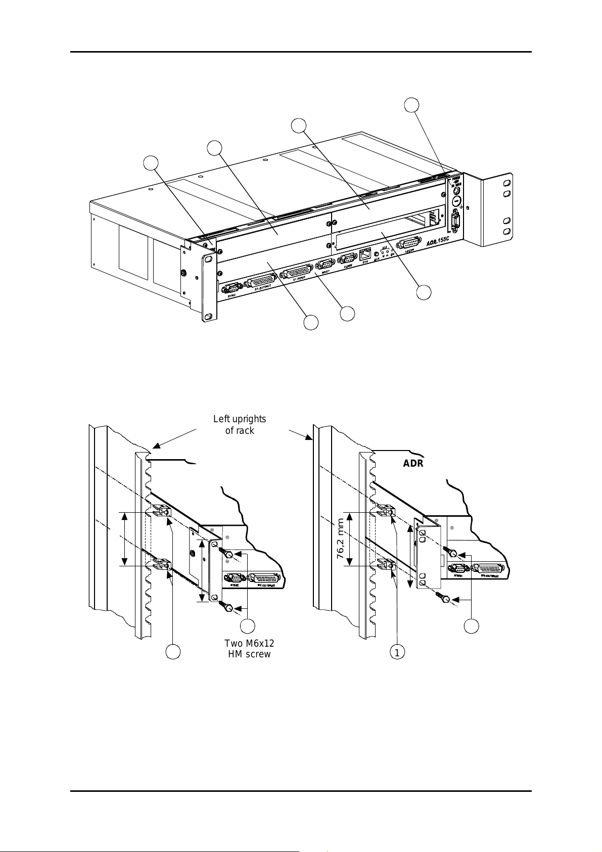
ADR 155C Subrack
ADR 155C
ETSI RACK
76 ,2 mm
6
(
6<1&
(
<1&
2
28
873
7387
87
2U
6
(
6<1&
(
<1&
2
28
873
7387
87
2 2
Two M6x12
1
HM screw
Two M6
cage nuts
19" rack mountin
Figure 1-1- ADR155C Subrack Installation
Installation and User Guide - N56717020101
Page A1-2
No reproduction or communication without the written cons ent of
1
Two M6
cage nuts
ETSI rack moutin
SAGEM SA
Two M6x12
HM screw
Page 11

1 - INSTALLATION AND COMMISSIONING
- Subrack
1.2
The ADR 155C subrack can be installed in 19" rack or ETSI fram e (see Figure 1-1). It consists
of:
a motherboard located in the lower part (item M),
four non-dedicated slots (items A to D), designed to accommodate the traffic cards,
a slide located on the left of the subrack designed to accom modate the ventilation module
(item V),
a power supply (item P).
All connections are performed on front panel, either on the subrack, or on the modules.
Installation in a 19" rack
Elements attaching the subrack in 19" rack (brackets, cage nuts and attaching screws), are
provided in its package.
The ADR155C has a system of therm al contr ol by ventilation ; during the installation, provide for
sufficient space for the ventilation aperture on the left of the subrack , and also f or the aeration,
at the top and right of the subrack. On the other hand, never hinder the natur al air convec tion on
the right side.
installation
Perform the following operations:
provide a 2U place in the rack for each equipment and a 1U space between equipments,
secure the attaching brackets for mounting in 19" rack, on either side of the subrack,
clip, on either side of the rack, two M6 cage nuts (item 1),
position the 19" subrack back in front of the rack,
slide the 19" subrack until attaching brackets are in contact with uprights, opposite the 4 cage
nuts, and then secure the subrack with 4 M6x12 hex head screws (item 2).
Installation in an ETSI rack
The installation of the subrack in ETSI rack is identical with that in 19" rack.
In this case, use the set of attaching brackets specific for mounting in ETSI rack.
Installation of cards
RECALL: Prior to any operation on the cards, the operator must be provided with an
antistatic bracelet.
ADR155C slots are non-dedicated. However, in order to make wiring easier and ensure the
homogeneity among sites, it is advisable to proceed as follows:
position the tributary cards from C clockwise
position the agregate cards from D counter-clockwise
check the ventilation module presence in its reserved slide,
secure each card through M3 screws of Torx type (6-branch star), using a suited screwdriver.
Installation and User Guide - N56717020101
No reproduction or communication without the written cons ent of
SAGEM SA
Page A1-3
Page 12

1 - INSTALLATION AND COMMISSIONING
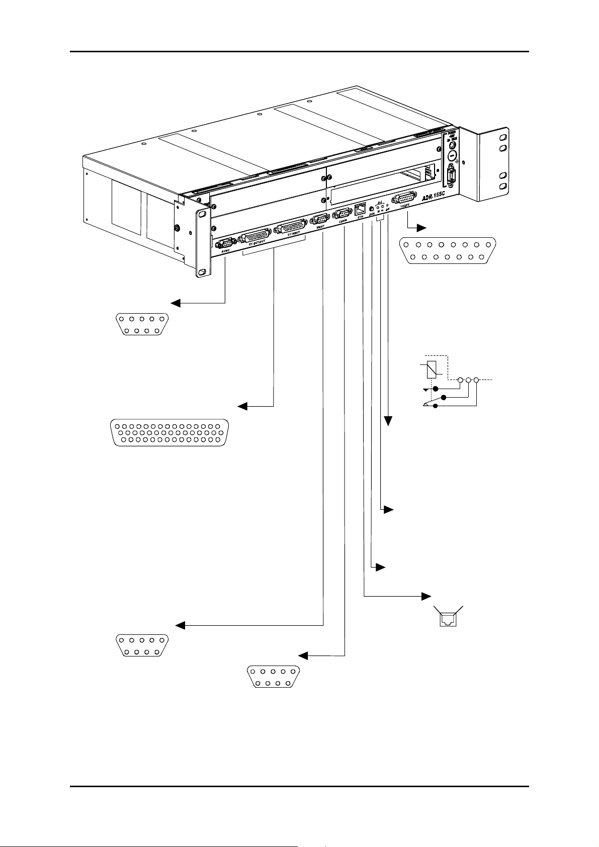
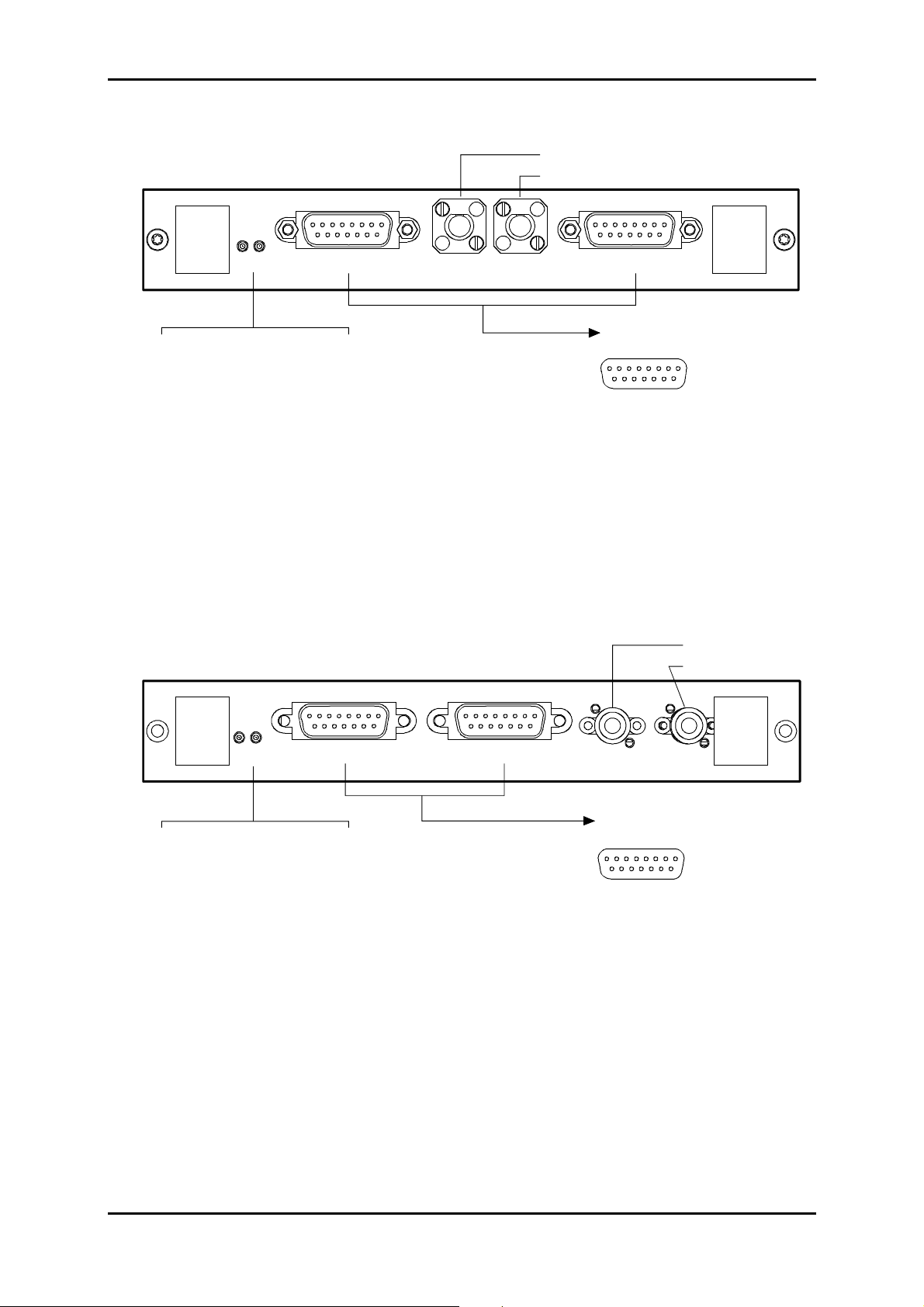
1.3 - Connecting ports
The connections to be performed on the equipment depend on the configuration chosen:
On the power supply card:
poser supply ports: "
PWR
" or "
PWRA
" and/or "
PWRB
",
On the subrack motherboard strip:
management ports : "
Remote indication, remote control and station alarm port : "
2Mbit/s G.703 synchronization port : "
21x2Mbit/s G.703 traffic ports: "
COMM
ETH"
", "
E1 INPUT
and/or "
SYNC
" and "
MNGT
"
E1 OUTPUT
"
LOOPS
"
".
Depending on the traffic modules used
optical STM-1 ports and order wire channels ports,
Ethernet port
21x2Mbit/s G.703 traffic ports.
Connection requirements :
Ö
For a right distribution of cords on either side of the subr ack, the connections of slots A and
C, the 21 2Mbit/s accesses and synchronization access are oriented leftward. All other
connections are oriented leftward.
Ö
The run of cords must not hinder the extraction of a module; in particular, connecting
cables of the left subrack half is to be secured to the frame with enough backlash to
enable the ventilation module to be extracted during a maintenance operation.
1.3.1 - Connecting Power Supply
"PWRA" and/or "PWRB" ports, when the equipment is powered from one or two 48 V
sources, the power source(s) should be limited to 100 VA.
. "PWR" port when the equipment is powered from a mains voltage (230 V AC), via an
optional 110-240//48V 60W/ transformer.
Observe the following connection requirements :
Ö
"PWR" and "PWRA" and/or "PWRB" Power supply ports can be connected simultaneously.
Ö
The power cord or the 110-240//48V 60W/ transf orm er m us t not be connected to the prim ar y
source prior to being connected to the equipment.
Ö
The 110-240//48V 60W/ transformer must be mounted far from any heat source, and no
traction must be exerted on its connecting wires.
Installation and User Guide - N56717020101
Page A1-4
No reproduction or communication without the written cons ent of
SAGEM SA
Page 13
1 - INSTALLATION AND COMMISSIONING
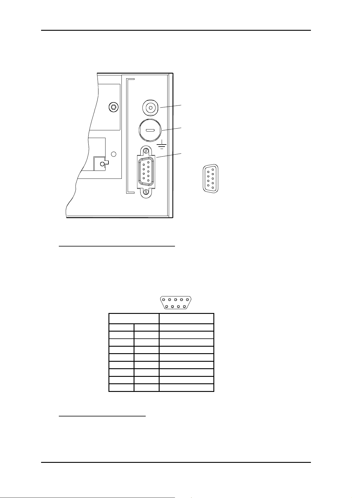
Description of power supply ports
POWER
- 48V
2A MAX
"PWR" Jack type connector
F4AL250V Fuse 4A Quick fuse
low power shutdown
250V
PWRA and PWRB
1 - 48 B1
5
9
6
1
2 - 48 B1 6 OB1
3 - Reserved 7 OB1
4 - 48 B2 8 OB2
5 - 48 B2 9 OB2
ADR-155C
Figure 1-2 – Connecting power supply ports
"PWRA"/"PWRB" power supply interface:
Input voltage : One or two Safety Extra Low Voltage (SELV) type – 48V sources
Voltage range allowed: - 36 V to - 60 V
Maximum voltage range : - 36 V to - 72 V
Power 100 VA maximum
Connector Male 9-way HE5
5
9
Pin N° Signal name
1 -48B1
6OB1
2 -48B1
7OB1
3 Reserved
8OB2
4 -48B2
9OB2
5 -48B2
1
6
NOTA : The shielding of the connector is connected to the equipment ground
"PWR" power supply interface:
Port Connecting transformer 110-240//48V 60W/
Connector Jack (core = OB1 and shield = - 48 V1).
Installation and User Guide - N56717020101
No reproduction or communication without the written cons ent of
SAGEM SA
Page A1-5
Page 14
1 - INSTALLATION AND COMMISSIONING
"SYNC"
5
9
1 : GND
2 : TX1_TIP 6 : TX1_RING
3 : RX1_TIP 7 : RX2_TIP
4 : RX2_RING 8 : RX1_RING
5 : RESERVED 9 : RESERVED
1
6
LOOPS
8
15
1 : Break B
2 : Make B 9 : Common B
3 : Common A 10 : Break A
4 : Gnd 11 : Make A
5 : R-MON 4 N 12 : R-MON 4 P (OB)
6 : R-MON 3 N 13 : R-MON 3 P (OB)
7 : R-MON 2 N 14 : R-MON 2 P (OB)
8 : R-MON 1 N 15 : R-MON 1 P (OB)
Schematic diagram
of a dry loop
M
CB
1
9
"E1 OUTPUT"and "E1 INPUT"
15 1
30
44 31
1 : Tx(Rx) 1A
2 : Tx(Rx) 3B
3 : Tx(Rx) 4A
4 : Tx(Rx) 6B
5 : Tx(Rx) 7A
6 : Tx(Rx) 9B
7 : Tx(Rx) 10A
8 : Tx(Rx) 12B
9 : Tx(Rx) 13A
10 : Tx(Rx) 15B
11 : Tx(Rx) 16A
12 : Tx(Rx) 18B
13 : Tx(Rx) 19A
14 : Tx(Rx) 21B
15 : GND
16 : GND
17 : Tx(Rx) 2B
18 : Tx(Rx) 3A
19 : Tx(Rx) 5B
20 : Tx(Rx) 6A
21 : Tx(Rx) 8B
22 : Tx(Rx) 9A
23 : Tx(Rx) 11B
24 : Tx(Rx) 12A
25 : Tx(Rx) 14B
26 : Tx(Rx) 15A
27 : Tx(Rx) 17B
28 : Tx(Rx) 18B
29 : Tx(Rx) 20B
30 : Tx(Rx) 21A
31 : Tx(Rx) 1B
32 : Tx(Rx) 2A
33 : Tx(Rx) 4B
34 : Tx(Rx) 5A
35 : Tx(Rx) 7B
36 : Tx(Rx) 8A
37 : Tx(Rx) 10B
38 : Tx(Rx) 11A
39 : Tx(Rx) 13B
40 : Tx(Rx) 14A
41 : Tx(Rx) 16B
42 : Tx(Rx) 17A
43 : Tx(Rx) 19B
44 : Tx(Rx) 20A
"MNGT"
5
9
1 : GND
2 : RXPA 6 : RXPB
3 : TXPA 7 : TXPB
4 : TXCLKPA 8 : TXCLKPB
5 : RXCLKPA 9 : RXCLKPB
1
6
16
COMM
5
9
1 : DCD
2 : RX 6 : DSR
3 : TX 7 : RTS
4 : DTR 8 : CTS
5 : Gnd 9 : NC *
Green "ON" LED
On
Flashing
Off
or not run software
"ALA" LEDs
Red "M" LED
ON : major alarm
Yellow "m" LED
OFF : minor alarm
"ACK"
alarm acquittement
In service card
Autotest default
No powered equipment
Push button
ETH
Pin 8Pin 1
1 : TX_ETH_TIP 5 : NC
2 : TX_ETH_RING 6 : RX_ETH_RING
3 : RX _ETH _TIP 7 : NC
4 : NC * 8 : NC
1
6
Yellow LED
ON : correct link
Green LED
ON : on reception
NC * : Reserved
: link status
: traffic status
Figure 1-3 – Connecting mother board inputs
Installation and User Guide - N56717020101
Page A1-6
No reproduction or communication without the written cons ent of
SAGEM SA
Page 15
1 - INSTALLATION AND COMMISSIONING
1.3.2 - Connecting on motherboard
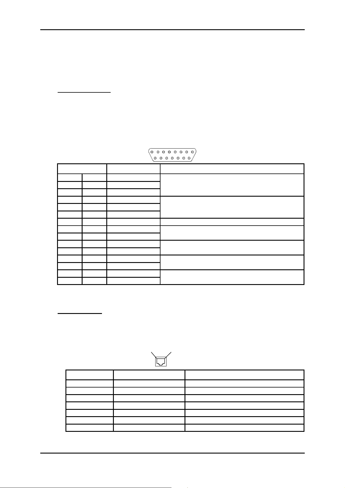
1.3.2.1 - Remote indication, remote control and station alarm port
("LOOPS")
"LOOPS" Interface:
Ports 4 remote indication inputs for floating contacts (
-48 V internally, active when closed and with electrical isolation
(loop current = from 1 to 10 mA),
2 dry loop outputs (common, normally closed and normally open) (
outputs
) for station alarm or remote control use (maximum current = 100 mA
on resistive load),
Connector Female 15-way HE5
8
15
Pin N° Signal name Comments
1 BREAK B Normally closed contact of dry loop B
9 COMMON B Common contact of dry loop B
2 MAKE B Normally open contact of dry loop B
10 Break A Norm al l y closed contact of dry loop A
3 COMMON A Common contact of dry l oop A
11 Make A Normally open contact of dry l oop A
4 GND Ground
12 R- MON 4 P (OB) User imput N°4
5R-MON 4 N
13 R- MON 3 P (OB) User imput N°3
6R- MON 3 N
14 R- MON 2 P (OB) User imput N°2
7R- MON 2 N
15 R- MON 1 P (OB) User imput N°1
8R- MON 1 N
NOTE: OB is the result of a logical "OR" between signals OB1 and OB2 on the "PW R", "PWRA" and "PWRB"
power supply interfaces.
1
9
Local user inputs
), biased to
Local user
"ETH" Interface:
Port Ethernet management interface operating at 10 Mbit/s in half-duplex or full-
duplex mode according to the mode used by the interlocutor (dynamic
adaptation of the Ethernet port on each new log-in of the interlocutor),
Connector RJ48 Type (RJ45 shielded).
Pin 1
Pin N° Signal name Comments
1 TX_ETH_TIP Output (hot point)
2 TX_ETH_RING Output (cold point)
3 RX_ETH_TIP Input (hot point)
4 NC Reserved
5 NC Reserved
6 RX_ETH_RING Input (cold point)
7 and 8 NC Reserved
Pin 8
Front view
Installation and User Guide - N56717020101
No reproduction or communication without the written cons ent of
SAGEM SA
Page A1-7
Page 16
1 - INSTALLATION AND COMMISSIONING
NOTE: Two LEDs are linked to the "ETH" port:
• LED, "Activity", green colour : Trafic status indicator,
• LED, "Link", yellow colour : Link status indicator.
1.3.2.2 - Management and Administration ports
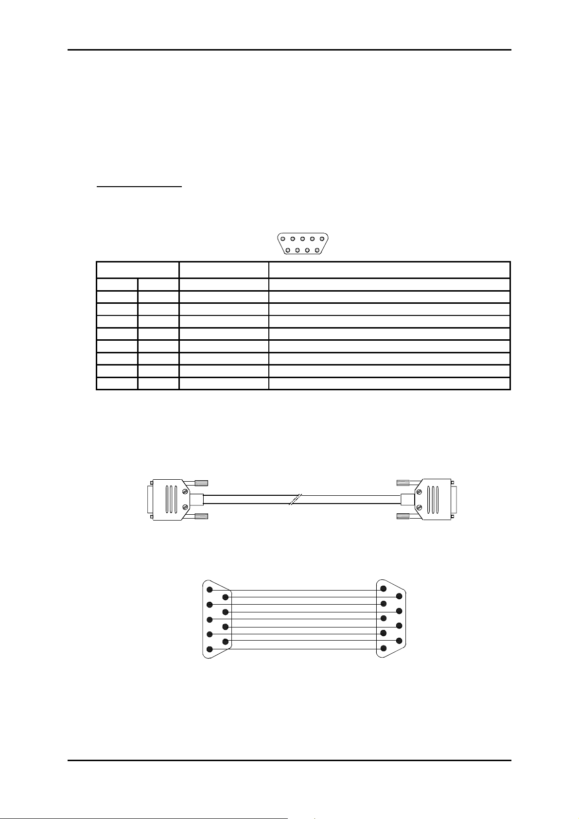
"COMM" Interface:
Ports RS232, connecting VT100 standard console or emulation
Bit rate 19200 bauds (8 data bits, no parity bit and 1 stop bit),
Connector Female 9-way HE5
5
9
Pin N° Signal name Comments
1 DCD Connected to DSR
6 DSR Data Set Ready (to DCE)*
2 RX Received dat a (to DCE)*
7 RTS Request To Send (from DCE)*
3 TX Transmitted data (from DCE)*
8 CTS Clear To Send (to DCE)*
4 DTR Data Terminal Ready (from DCE)*
9 RI Ring Indicator (not connect ed)
5 GND Ground
* The ADR155C is seen as DCE
1
6
Connection cable See below.
Equipment side
"COMM"
Male 9-way connector
1
6
9
5
Wiring diagram
VT100 or PC
side
Female 9-way connector
1
6
9
5
Installation and User Guide - N56717020101
Page A1-8
No reproduction or communication without the written cons ent of
SAGEM SA
Page 17
1 - INSTALLATION AND COMMISSIONING
)
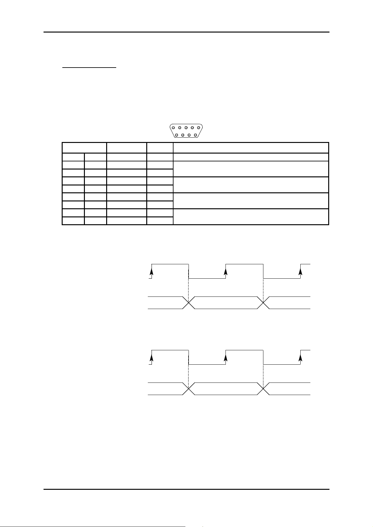
"MNGT" Interface:
Port V.11 synchronous (differential) interconnection possible with other SAGEM
equipment ADR155C, FOT 155C, through serial synchronous links used in
codirectional mode at 64 kbit/s or master contra-directional mode (rate
defined by the ADR 155C)
Bit rate 64 kbit/s,
Connector Female 9-way HE5.
5
9
Pin N° Signal name Polarity Comments
1 GND Ground (no connected)
6RXPB(+)
2 RXPA (-)
7TXPB(+)
3 TXPA (-)
8 TXCLKPB (+)
4 TXCLKPA (-)
9 RXCLKPB (+)
5 RXCLKPA (-)
Input for data received over the P interface and sampled on the
rising edge of receive cloc k RXCLKP (B-A)
Output for data sent over the P interface on the falling edge of
transmit clock TXCLKP (B-A)
Output for transmit cloc k; in codirectional mode, the transm it clock
timing is derived from the equipment's i nt ernal timing
Receive clock input
1
6
*In slave contradirectional mode (coming) TXCLK signals are inputs.
Timing diagram for the "MNGT" interface in codirectional mode (64 kbit/s synchronous use):
TXCLKP (B-A)
(codirectional transmit
clock output)
TXP (B-A)
(output for data transmitted
over P interface)
B8 B1 B2
RXCLKP (B-A)
(receive clock input)
RXP (B-A)
(input for data received
over the P interface
B8 B1 B2
Installation and User Guide - N56717020101
No reproduction or communication without the written cons ent of
SAGEM SA
Page A1-9
Page 18

1 - INSTALLATION AND COMMISSIONING
1.3.2.3 - G.703 2 Mbit/s Synchronization port
"SYNC" Interface
Ports Two G.703 2MHz external synchronization inputs (T3) and one G.703 2MHz
clock output (T4) compliant with ITU-T G.703 Recommendation
(§ 10.3 for input port, § tab.10 for output port)
Bit rate 2,048 Mbit/s ± 50 ppm,
Impedance 120 Ω balanced,
Connector Female 9-way HE5 (120 Ω).
5
9
Pin N° Signal name Comments
1 GND Ground
6 TX1 RING (T4-) Output T4-1 (cold point)
2 TX1 TIP (T4+) Output T4-1 (hot point)
7 RX2 TIP (T3+) Input T3-2 (hot point)
3 RX1 TIP (T3+) Input T3-1 (hot point)
8 RX1 RING (T3-) Input T3-1 (cold point)
4 RX2 RING (T3-) Input T3-2 (cold point)
9 NC Reserved
5 NC Reserved
1
6
NOTA : The shielding of the connector case is connected to the subrack front panel ground
1.3.2.4 - G.703, 21 x 2 Mbit/s traffic port
"E1 INPUT" and "E1 OUTPUT" Interface
ports 21 x 2 Mbit/s traffic ports compliant with the ITU-T G.703 Recommendation
(§ 6.3 for input port, § tab.6 for output port)
Bit rate 2,048 Mbit/s ± 50 ppm,
Code HDB3,
Impedance 120 Ω balanced,
Connector SUB D HD female 44 pins supporting L907 cable (21 ports).
This interface uses two connectors : E1 INPUT connector for inputs (named RX) and
E1 OUTPUT connector for outputs (named TX)
15
30
44 31
1
16
Installation and User Guide - N56717020101
Page A1-10
No reproduction or communication without the written cons ent of
SAGEM SA
Page 19

1 - INSTALLATION AND COMMISSIONING
Pin N°
16
31
1
17
2
32
18
33
3
19
4
34
20
35
5
21
6
36
22
37
7
23 11
8
38
12
24
39
9
25 14
10
40
15
26
41
11
27
12
42
28
13
43
29
14
44
30
15
Ports Signal name
GND
1
2
3
4
5
6
7
8
9
10
13
16
17
18
19
20
21
TX(RX) 1B
TX(RX) 1A
TX(RX) 2B
TX(RX) 2A
TX(RX) 3B
TX(RX3A
TX(RX) 4B
TX(RX) 4A
TX(RX) 5B
TX(RX) 5A
TX(RX) 6B
TX(RX) 6A
TX(RX) 7B
TX(RX) 7A
TX(RX) 8B
TX(RX) 8A
TX(RX) 9B
TX(RX) 9A
TX(RX) 10B
TX(RX) 10A
TX(RX) 11B
TX(RX) 11A
TX(RX) 12B
TX(RX) 12A
TX(RX) 13B
TX(RX) 13A
TX(RX) 14B
TX(RX) 14A
TX(RX) 15B
TX(RX) 15A
TX(RX) 16B
TX(RX) 16A
TX(RX) 17B
TX(RX) 17A
TX(RX) 18B
TX(RX) 18A
TX(RX) 19B
TX(RX) 19A
TX(RX) 20B
TX(RX) 20A
TX(RX) 21B
TX(RX) 21A
GND
Comments
ground
Output (Input) 2 Mbit/s (hot poi nt)
Output (input) 2 Mbit/s (cold poi nt)
Output (Input) 2 Mbit/s (hot poi nt)
Output (input) 2 Mbit/s (cold poi nt)
Output (Input) 2 Mbit/s (hot poi nt)
Output (input) 2 Mbit/s (cold poi nt)
Output (Input) 2 Mbit/s (hot poi nt)
Output (input) 2 Mbit/s (cold poi nt)
Output (Input) 2 Mbit/s (hot poi nt)
Output (input) 2 Mbit/s (cold poi nt)
Output (Input) 2 Mbit/s (hot poi nt)
Output (input) 2 Mbit/s (cold poi nt)
Output (Input) 2 Mbit/s (hot poi nt)
Output (input) 2 Mbit/s (cold poi nt)
Output (Input) 2 Mbit/s (hot poi nt)
Output (input) 2 Mbit/s (cold poi nt)
Output (Input) 2 Mbit/s (hot poi nt)
Output (input) 2 Mbit/s (cold poi nt)
Output (Input) 2 Mbit/s (hot poi nt)
Output (input) 2 Mbit/s (cold poi nt)
Output (Input) 2 Mbit/s (hot poi nt)
Output (input) 2 Mbit/s (cold poi nt)
Output (Input) 2 Mbit/s (hot poi nt)
Output (input) 2 Mbit/s (cold poi nt)
Output (Input) 2 Mbit/s (hot poi nt)
Output (input) 2 Mbit/s (cold poi nt)
Output (Input) 2 Mbit/s (hot poi nt)
Output (input) 2 Mbit/s (cold poi nt)
Output (Input) 2 Mbit/s (hot poi nt)
Output (input) 2 Mbit/s (cold poi nt)
Output (Input) 2 Mbit/s (hot poi nt)
Output (input) 2 Mbit/s (cold poi nt)
Output (Input) 2 Mbit/s (hot poi nt)
Output (input) 2 Mbit/s (cold poi nt)
Output (Input) 2 Mbit/s (hot poi nt)
Output (input) 2 Mbit/s (cold poi nt)
Output (Input) 2 Mbit/s (hot poi nt)
Output (input) 2 Mbit/s (cold poi nt)
Output (Input) 2 Mbit/s (hot poi nt)
Output (input) 2 Mbit/s (cold poi nt)
Output (Input) 2 Mbit/s (hot poi nt)
Output (input) 2 Mbit/s (cold poi nt)
Ground
NOTA : The shielding of the connector case is connected to the subrack front panel ground
Installation and User Guide - N56717020101
No reproduction or communication without the written cons ent of
SAGEM SA
Page A1-11
Page 20
1 - INSTALLATION AND COMMISSIONING
ADR IC1
STM1 transmission port
STM1 reception port
STATUS
LED STATUS
Green Red
ON OFF Card in service
ON ON Card in alarm
OFF OFF Hardware default (fuse)
OFF ON Card out of service
Flashing Autotest default
ADR IC1.1
TR REC
Version 1
AUXEOW
"
EOW and "AUX
81
15
1 : NC
2 : TA 9 : TB
3 : TOF PA 10 : TOF PB
4 : RA 11 : RB
5 : ROF PA 12 : ROF PB
6 : R64 A 13 : R64 B
7 : T64 A 14 : T64 B
8 : GND 15 : NC
"
9
STM1 transmission port
STM1 reception port
STATUS
LED STATUS
Green Red
ON OFF Card in service
ON ON Card in alarm
OFF OFF Hardware default (fuse)
OFF ON Card out of service
Flashing Autotest default
EOW AUX
Figure 1-4 - Connecting ADR IC1.x card inputs
Version 2
TR REC
"
EOW and "AUX
81
15
1 : NC
2 : TA 9 : TB
3 : TOF PA 10 : TOF PB
4 : RA 11 : RB
5 : ROF PA 12 : ROF PB
6 : R64 A 13 : R64 B
7 : T64 A 14 : T64 B
8 : GND 15 : NC
"
9
NC: Reserved
Installation and User Guide - N56717020101
Page A1-12
No reproduction or communication without the written cons ent of
SAGEM SA
Page 21

1 - INSTALLATION AND COMMISSIONING
1.3.3 - Connecting on the ADR IC1.x card
Each ADR IC1.x module provides connection for:
an STM1 interface ("TR" transmission port and "
two order wire channels at 64 kbit/s (named "EOW" and "AUX"), which, by default, are
conveyed in E1 and F1 bytes of the SOH, respectively.
REC
1.3.3.1 - Connecting STM1 interface
Remove the contact protection connector,
Connect STM-1 interface to front panel FC/PC connectors:
Ö
Transmission TR Connector
Ö
Reception REC Connector
"TR" and "REC" ports:
" reception port)
Interface Type IC 1.1 = L 1.1 + S 1.1 or IC 1.2 = L 1.2 + S 1.2,
Bit rate 155.520 Mbit/s ± 15 ppm,
Standart ITU-T G.957/G.958,
Encoding Not encoded (NRZ),
Optical fiber* Single mode (1300 nm (IC1.1) or
1550 nm (IC1.2), ITU-T G.652),
Transmit optical power -5 to 0 dBm
Max. receive power 0 dBm
Sensibility at 10
garanteed Attenuation 0 - 28 dB with no external attenuator,
Typical range 0 - 60 km (IC1.1) or 0 - 90 km (IC1.2),
Connector all ceramic FC/PC
* : It is pos sible to use a multi-mode optical fiber with diameter sm aller than or equal to 62.5
microns. The optic al budget is then reduced to 25 % of the optical budget obtained with a
mono-mode optical f iber . T he tr ansmission optical fiber is mono-mode type and the reception
optical fiber is multi-mode type.
-10
- 34 dB
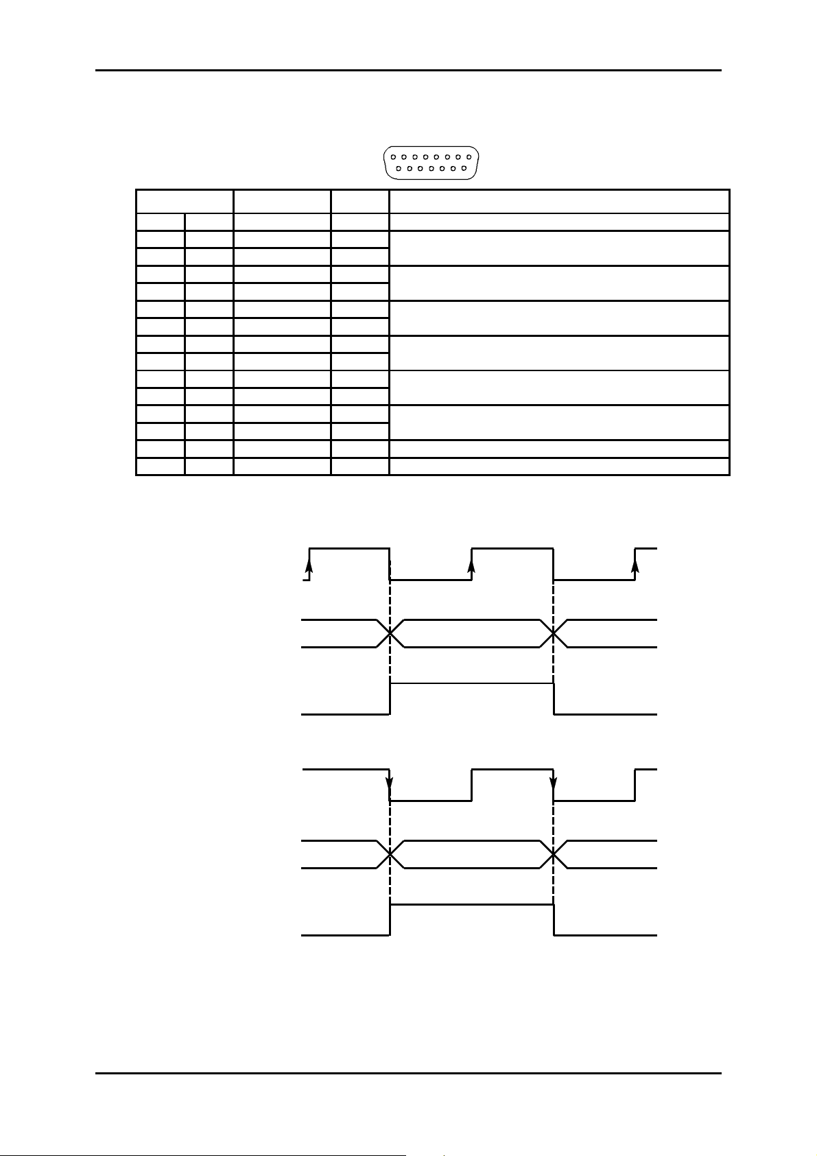
1.3.3.2 - Connecting order-wire channels
"EOW" and "AUX" Interface:
Port synchronous V.11 (differential),
Bit rate 64 kbit/s,
Installation and User Guide - N56717020101
No reproduction or communication without the written cons ent of
SAGEM SA
Page A1-13
Page 22
1 - INSTALLATION AND COMMISSIONING
9
)
Connector Female 15-way HE5.
81
15
Pin N° Signal name Polarity Comments
1 - Not connected
9TB(+)
2 TA (-)
10 TOFPB (+)
3 TOFPA (-)
11 RB (+)
4 RA (-)
12 ROFPB (+)
5 ROFPA (-)
13 R64B (+)
6 R64A (-)
14 T64B (+)
7 T64A (-)
15 - Not connected
8 Ground
Input for data to send over the STM-1 line and sampled on the
rising edge of clock T64 (B-A)
Transmit mode byte sync output indicating the positioning of bit 1
and sent on the rising edge of clock T64 (B-A)
Output for data extracted from STM-1 line and sampled on the
falling edge of clock T64 (B -A)
Receive mode byte sync output indicating the setting of bit 1 and
sent on the falling edge of cl ock T64 (B-A)
64 kHz receive clock output
64 kHz transmit cl ock output
Timing diagram f or the "EOW /AUX" interfac e in contra-directional m ode (64 k bit/s synchronous
use):
T64 (B-A)
(transmit clock output)
T (B-A)
(input for data to transmit
over STM1 line)
TOFP (B-A)
(transmit synchro byte
pulse output)
R64 (B-A)
(receive clock output)
R (B-A)
(output for data received
from STM1 line)
B8 B1 B2
B8 B1 B2
ROFP (B-A)
(receive synchro b yte
pulse output
Installation and User Guide - N56717020101
Page A1-14
No reproduction or communication without the written cons ent of
SAGEM SA
Page 23
1 - INSTALLATION AND COMMISSIONING
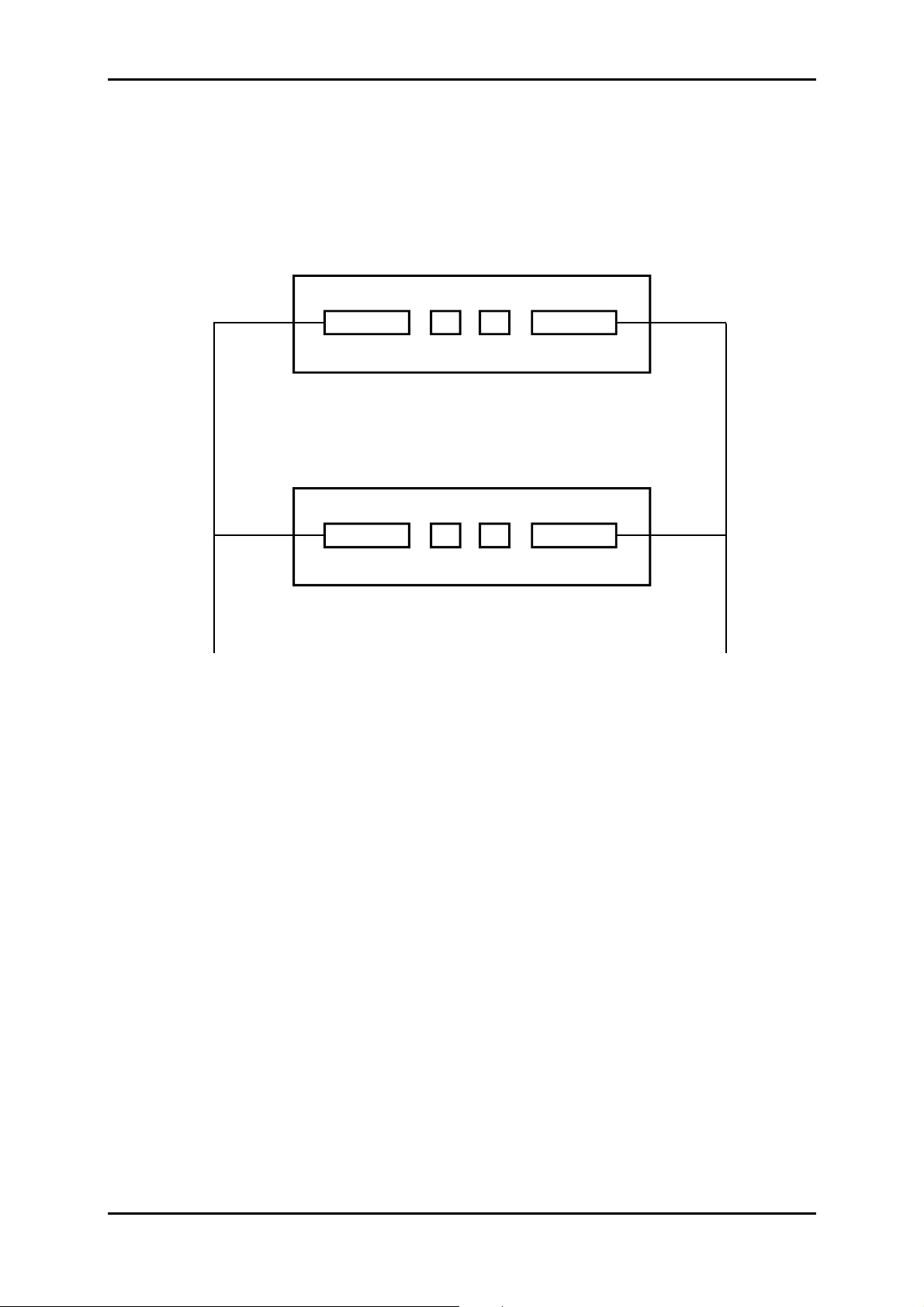
1.3.3.3 – Connecting with MSP operati on
As EOW and AUX ports are physically integral with ADR IC1.x, operating the order wire and
auxiliary channels with MSP protection requires the use of a "Y" cord elec tr ically connecting, one
by one, identically, the signals of EOW and AUX connectors.
EOW
ADR IC1.x Working
EOW
ADR IC1.x Prot ection
"Y" cord for
order wire
channel operation
TRTRREC
REC
AUX
AUX
"Y" cord for
auxiliar y wire
channel operation
Likewise, in order to ensure a good behaviour during the changeover from one m odule to the
other, the operator should take care to k eep identical c onfigur ations on both ADR IC1.x cards ; a
warning message appears in case of modification.
Only the connections are not identical. There must be no connections on the "Protection"
module, as in all the connections are made to the "Working" module.
Installation and User Guide - N56717020101
No reproduction or communication without the written cons ent of
SAGEM SA
Page A1-15
Page 24
1 - INSTALLATION AND COMMISSIONING
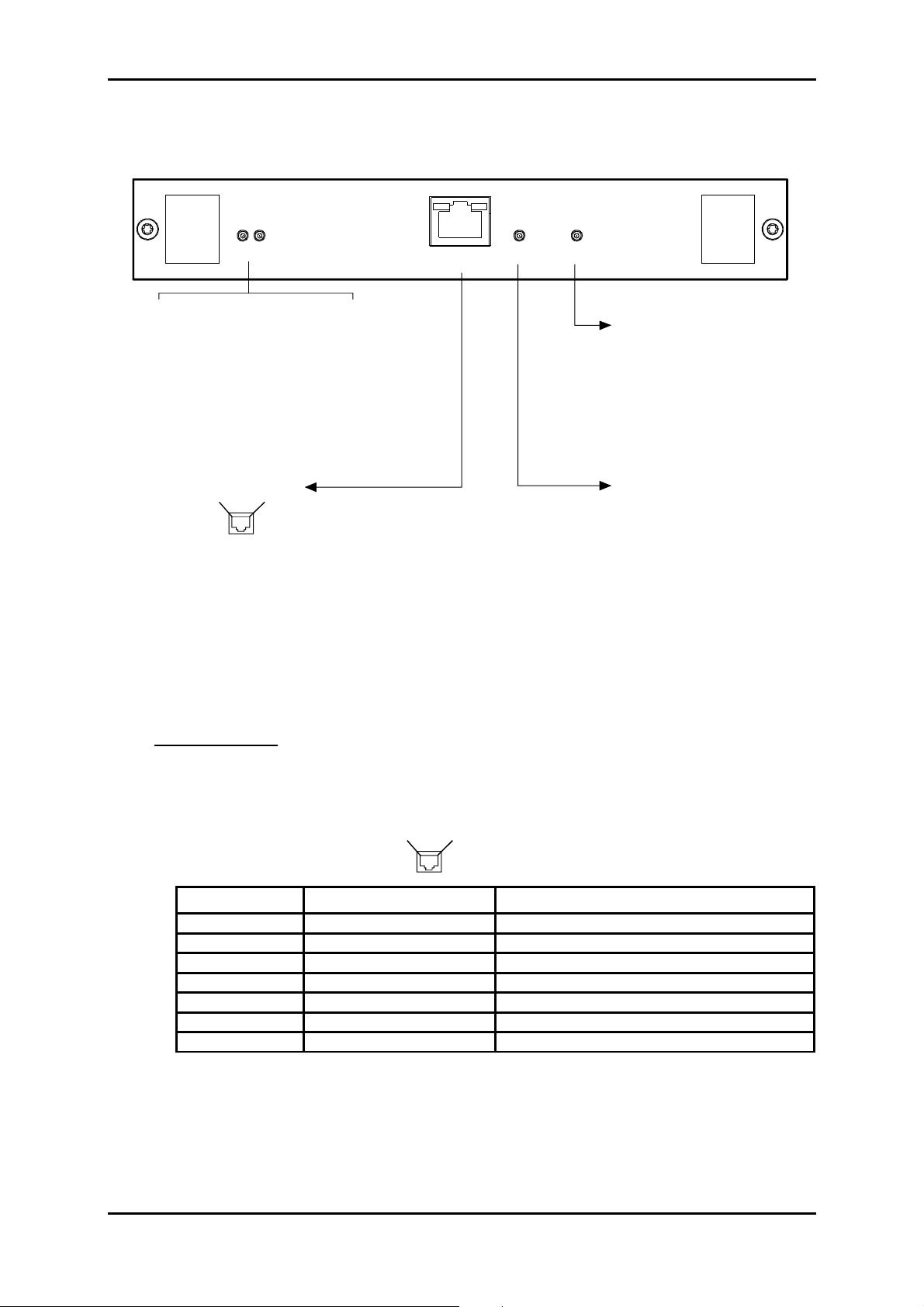
1.3.4 - Connecting on ADR LAN1 card
ADR LAN1
STATUS
ETH
/
10
100 HALF/FULL
LED STATUS
Green Red
ON OFF Card in service
ON ON Card in alarm
OFF OFF Hardware default (fuse)
OFF ON Card out of service
Flashing Autotest default
ETH
Contact 8Contact 1
1 : TX_ETH_TIP 5 : NC
2 : TX_ETH_RING 6 : RX_ETH_RING
3 : RX _ETH _TIP 7 : NC
4 : NC 8 : NC
Yellow LED
ON : correct link
Green LED
ON : on reception
: link status
: traffic status
NC : Reserved
HALF/FULL
Yellow LED :
(Half or Full Duplex)
ON : Full duplex
10/100
Yellow LED :
ON : 100 Mbit/s
Ethernet interface type
Ethernet interface bite rate
Figure 1-5 – Connecting ADR LAN1 card input
"ETH" Interface :
Port Traffic Ethernet interface operating at 10 or 100 Mbit/s in half-duplex or full-
duplex mode according to the mode used by the interlocutor (dynamic
adaptation of the Ethernet port on each new log-in of the interlocutor),
Connector Ethernet 10 or 100 BaseT - RJ48 Type (Shielded RJ45).
Pin 1
Pin 8
Front view
Pin N° Signal name Comments
1 TX_ETH_TIP Ethernet output (hot point)
2 TX_ETH_RING Ethernet output (cold point)
3 RX_ETH_TIP Ethernet input (hot point)
4 NC Reserved
5 NC Reserved
6 RX_ETH_RI NG Ethernet i nput (cold point)
7 and 8 NC Reserved
NOTE: Two LEDs are linked to the "ETH" interface:
• LED, "Activity", green colour : Trafic status indicator,
• LED, "Link", yellow colour : Link status indicator.
Electrical characteristics compliant with the IEEE 802.3U
Installation and User Guide - N56717020101
Page A1-16
No reproduction or communication without the written cons ent of
SAGEM SA
Page 25
1 - INSTALLATION AND COMMISSIONING
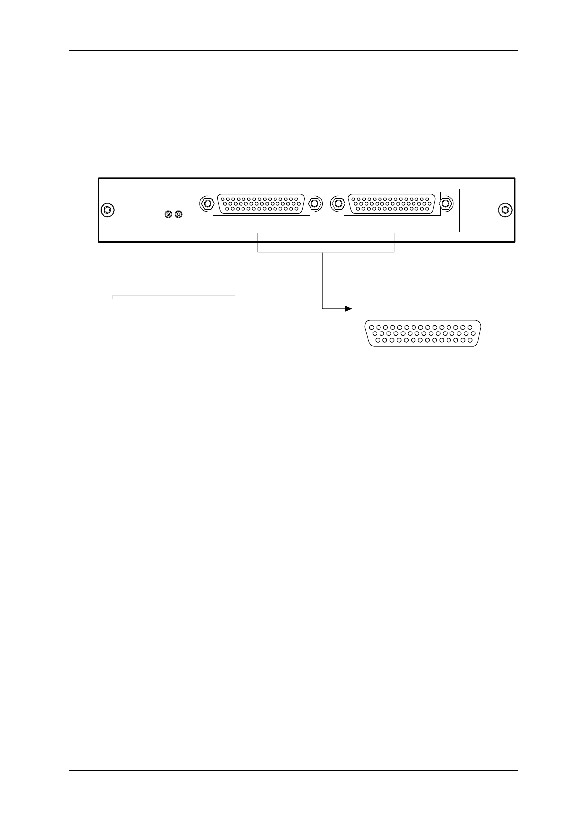
1.3.5 - Connecting on ADR 21E120 card
2 Mbit/s traffic connections, performed on "
E1 INPUT"
ADR21E120 card are identical with those perform ed on "
on the front side of the motherboard (see § 1.3.2.4)
ADR 21E120
STATUS
LED STATUS
Green Red
ON OFF Card in service
ON ON Card in alarm
OFF OFF Hardware default (fuse)
OFF ON Card out of service
Flashing Autotest default
E1 OUTPUT E1 INPUT
1 : Tx(Rx) 1A
2 : Tx(Rx) 3B
3 : Tx(Rx) 4A
4 : Tx(Rx) 6B
5 : Tx(Rx) 7A
6 : Tx(Rx) 9B
7 : Tx(Rx) 10A
8 : Tx(Rx) 12B
9 : Tx(Rx) 13A
10 : Tx(Rx) 15B
11 : Tx(Rx) 16A
12 : Tx(Rx) 18B
13 : Tx(Rx) 19A
14 : Tx(Rx) 21B
15 : GND
and
"E1 OUTPUT"
E1 INPUT"
and
ports on the
"E1 OUTPUT"
"E1 OUTPUT" and "E1 INPUT"
15 1
30
44 31
16 : GND
17 : Tx(Rx) 2B
18 : Tx(Rx) 3A
19 : Tx(Rx) 5B
20 : Tx(Rx) 6A
21 : Tx(Rx) 8B
22 : Tx(Rx) 9A
23 : Tx(Rx) 11B
24 : Tx(Rx) 12A
25 : Tx(Rx) 14B
26 : Tx(Rx) 15A
27 : Tx(Rx) 17B
28 : Tx(Rx) 18B
29 : Tx(Rx) 20B
30 : Tx(Rx) 21A
31 : Tx(Rx) 1B
32 : Tx(Rx) 2A
33 : Tx(Rx) 4B
34 : Tx(Rx) 5A
35 : Tx(Rx) 7B
36 : Tx(Rx) 8A
37 : Tx(Rx) 10B
38 : Tx(Rx) 11A
39 : Tx(Rx) 13B
40 : Tx(Rx) 14A
41 : Tx(Rx) 16B
42 : Tx(Rx) 17A
43 : Tx(Rx) 19B
44 : Tx(Rx) 20A
ports
16
Figure 1-6 – Connecting ADR 21E120 card inputs
Installation and User Guide - N56717020101
No reproduction or communication without the written cons ent of
SAGEM SA
Page A1-17
Page 26

1 - INSTALLATION AND COMMISSIONING
1.3.6 - 75 Ω connecting strip
Drafting TBD
Figure 1-7 - 75 ΩΩ connecting strip
Installation and User Guide - N56717020101
Page A1-18
No reproduction or communication without the written cons ent of
SAGEM SA
Page 27
1 - INSTALLATION AND COMMISSIONING
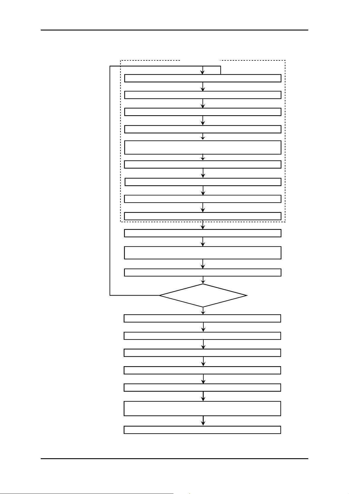
LOCAL TEST
Equipment Inventory
- 48 V power Check
Aggregate optical loopback
Insertion of communication parameters (VT100)
* case of underequipped
unitary equipment
Settin g to time and insertion of the test configuration tributary accesses
Connecti on of external sync input from of an "Master" equipment
no
(HTTP browser)
Tributary Ports continuity ch eck
- 48 V redundancy Check
A and B loops and alarms check
Local tr ansmission test (30 m n ) *
Optical connection
(optional)
Configuration Elaboration
Local Test on network
of last équi pm ent ?
yes
Link established
Optical m easurements
MSP protection check
Counters reset
24 H link Performance
Equipment operational
(constitution of in stallat ion file)
Configuration Save
Figure 1-8 – Commissioning procedure for ADR155C network
Installation and User Guide - N56717020101
No reproduction or communication without the written cons ent of
SAGEM SA
Page A1-19
Page 28

1 - INSTALLATION AND COMMISSIONING
1.4 - Commissioning
: The equipm ent can be operated from a PC fitted with VT 100 emulation and HT TP navigator;
NOTE
its minimum configuration is defined in section 1.4.1.
A local terminal with VT100 emulation is indispensable during the first commissioning, in
order to be able to access the equipment via the management function; however, this
terminal only enables the communication function to be parameterized.
Procedure.
)
On the first commissioning, the equipment scans its constitution and considers it as the
expected configuration, in service, not monitored. It is thus advisable to insert the traffic
cards before power-up, in order to speed up the commissioning.
)
Switch on the power supply connected to the equipment.
)
The equipment conducts self-tests:
When self-tests have run correctly, the "ON" indicator light is illuminating,
In the opposite case, an indicator flashing code defines the faulty self-test (c ontact the
hotline).
)
Parameterize the communication interface, using the VT100 (see § 1.4.1).
)
Using the HTTP navigator, (see § 1.4.3).
Update the equipment time and date
Set each card under monitoring: validate the "Monitoring" command.
)
Connect the 2 Mbit/s and/or Ethernet ports, according to the equipment composition,
)
Connect the AUX and EOW ports required.
)
Download a predefined configuration or prepare the desired configuration, using the HTTP
navigator:
Create the connections
Establish the wished protection (MSP protection, SNC protection ...)
Choose the synchronization source, and change its parameters if required.
Change, if necessary, the configuration parameters and the alarm configuration.
The default configuration of the various parameters is provided by § 2.1.1.
)
Conduct the tests on STM-1 links, complying with the process described in Figure 1-2.
)
From that moment, the equipment is operational.
)
Operating alarms can signal a wrong connec tion of interfaces. Chec k the connection of por ts,
the alarms corresponding to the connected ports, and correct any problems that may arise.
)
Save configuration.
REMARK: It is possible, once the commissioning is perf orm ed, to connect additional 2 Mbit/s G .703,
Ethernet or STM1 ports, and to insert or extract powered cards.
Installation and User Guide - N56717020101
Page A1-20
No reproduction or communication without the written cons ent of
SAGEM SA
Page 29
1 - INSTALLATION AND COMMISSIONING
g
T
HTP
E
T
H
R
SN PM
P
P
P
Communication function over an ADR 155C
D1 - D3 over STM1 D1 - D3 over STM1
HT PT
E
T
H
R
SN PM
P
P
P
Example 1 : communication over a point to point link
Mngt port
ETH port
.
4 PPP ports
.
(Point to Point Protocol)
x
x
x
Application
HTTP server
.
SNNP agent for
.
IONOS ANM
R
Routing
function
HT PT
P
P
P
R
SN PM
E
T
H
The TPI can be connec ted to any
Ethernet int erf ace as soon as the
parametere zing enables to reach
1 equipment to be ope rated
E
ADR
IONOS ANM in neces sary
to operate this FOT C
(but the ADR cannot be
operated from the ETH
interface of the F OT C
T
H
FOT C *
E
T
H
R
SN PM
P
P
P
HT PT
R
SN PM
- D3
D
1
on STM1
aggregate
P
P
P
- D3
D
1
on STM1
tributary
D1 - D3 STM1
on East
- D3 STM1
D
1
on West
S
N
M
P
D1 - D3
STM1
on West
- D3
D
1
STM1
on East
S
N
M
P
IONOS ANM
HT
E
R
PPP
PPP
R
HTE
H
T
T
P
- D3
D
1
STM1
on East
- D3
D
1
STM1
on West
H
T
T
P
ADR
ADR
Example 2 : communication over an ADR 155C and FOT 155C rin
Figure 1-9 – Examples of the communication function configuration
Installation and User Guide - N56717020101
No reproduction or communication without the written cons ent of
SAGEM SA
Page A1-21
Page 30
1 - INSTALLATION AND COMMISSIONING
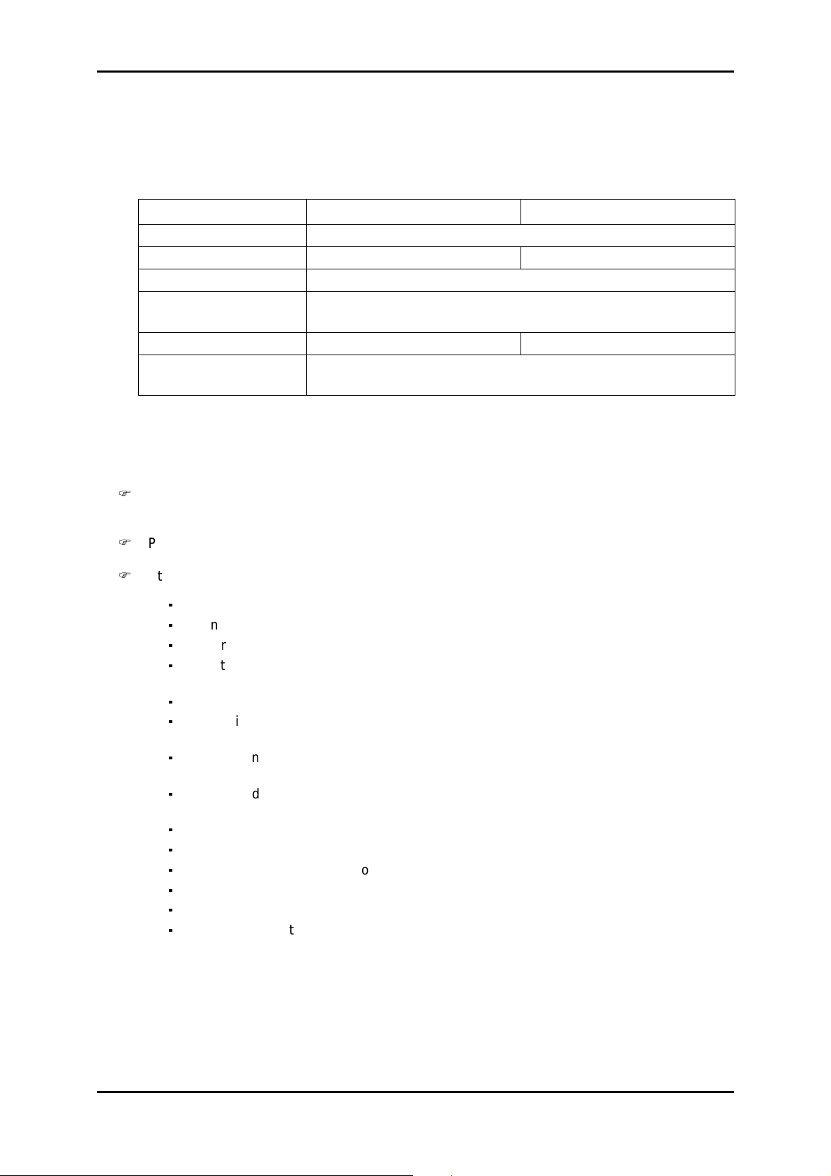
1.4.1 - Configuration required
The minimum configuration proposed for the operating PC is as follows:
Description Configuration 1 Configuration 2
Processor 266 MHz Pentium
Memory 32 MB 64 MB
Display 800x600, 256 colours (1024x768 recommended)
Interface Serial RS232 interface
Ethernet 10 base T network card
Operating system Windows 95 Windows NT4
Applications Hyperterminal for Windows
HTTP navigator: Netscape Communicator 4.5
1.4.2 - Parameterizing the communication function
Figure 1-9 presents the available resources and various configurations possible for the
communication function;
)
Connect "
COMM
" port of the equipment to a "COM" port not used on the PC with VT100
emulation,
)
Power the PC on,
)
Start the Hyper Terminal application
on the first use, proceed as follows:
connect "
power the PC on,
select, in succession, from Windows desktop, the Start, Programs, Accessories and
COMM
" port of the equipment to a "COM" port not used on the PC,
HyperTerminal command buttons,
choose the icon representative of the HyperTerminal application,
a description window for the connection appears; give a nam e for the connection and
validate your choices,
a new window appears; choose that PC "COM" port which is connected to the
equipment and validate your choice,
a new window appears; configure the port parameters as indicated below and validate
the programming :
. Bits per second : 19200,
. Data bits : 8,
. Parity : no parity,
. Stop bits : 1,
. Flow control : none,
save the connection (Save command in the application File menu).
NOTE
: On the next opening of "Hyperterm inal" application, choosing the connection icon
will be enough to be logged on the equipment.
On the equipment power-up, the operating menu appears.
To exit the "Hyperterminal" application, select Quit command from File menu.
Installation and User Guide - N56717020101
Page A1-22
No reproduction or communication without the written cons ent of
SAGEM SA
Page 31

1 - INSTALLATION AND COMMISSIONING
)
Open a session and enter your password (to param eterize the communication f unction, it is
indispensable to have "supervisor" rights).
NOTE : By default, on the first commissioning, the password is empty.
)
The following menu appears:
To select a command, type the command number in "Choice ?" text zone, and press
"ENTER" key to validate your choice.
)
Choice "1" : Configuration of communication interface,
Installation and User Guide - N56717020101
No reproduction or communication without the written cons ent of
SAGEM SA
Page A1-23
Page 32

1 - INSTALLATION AND COMMISSIONING
The screen displays the 5 communication interfaces possible, with their characteristics, and
proposes to change each of them by turns. These interfaces are:
- an Ethernet port –ETH
- 4 PPP (Point to Point Protocol) portes – PPP1 to PPP4 - to be chosen from the following
management paths:
either at bytes D1 to D3 of channel DCC1 of an STM1 frame (named DCC1-A, DCC1-B,
DCC1-C or DCC1-D according to the number and position of ADR IC1.x modules in the
equipment), or the MNGT interface
Each interface is defined by its characteristics:
- "Port" : physical port "ETH", "PPP1" to "PPP4"
- "Admin" or interface state: "ON" (interface active) or "OFF" (interface inactive)
- "@ IP" : IP address
- "subnet mask" : subnetwork mask
- "@ IP of dest" : destination IP address (for PPP ports only)
- "Path" : management path chosen for the PPP ports (DCC1x or MNGT)
- "RIP" : management routing self-adaptability to the network struc ture validated or not (limited
to 16 hops without gateway)
The parameterization is backed up port by port.
)
Choice "2" : Configuration of static routes,
The screen displays the already defined management routes with their characteristics:
- "No" : reference of the route
- "destination @ IP" : destination IP address (equipment or subnetwork)
- "subnet mask" : subnetwork mask
- "next hop @ IP" : IP address of the next equipment (connected on line with the given
equipment)
Installation and User Guide - N56717020101
Page A1-24
No reproduction or communication without the written cons ent of
SAGEM SA
Page 33

"interface" : interface used to reach the next equipment
"cost" : or "metric", number of hops to reach the destination.
From this screen, it is possible to change the existing routes , to delete them or to create new
ones (the static routing is necessary if FOT155C's are present on the network or for an
interconnection with a contiguous network).
)
Choice "3" : Display of routing information,
1 - INSTALLATION AND COMMISSIONING
This screen is used to view the routing table, to list the dynamic and/or static routes and also the
interface configurations
)
Choice "4" : equipment REBOOT,
This command is used to perform immediate application REBOOT and to restart with the
parameters already stored in the equipment .
)
Choice "5" : Logout
With the parameterization being complete, this command closes the current session.
An automatic session ex it is performed after a few m inutes of inactivity (time parameterizable
from the manager).
Installation and User Guide - N56717020101
No reproduction or communication without the written cons ent of
SAGEM SA
Page A1-25
Page 34

1 - INSTALLATION AND COMMISSIONING
1.4.3 - Using HTTP navigator
1.4.3.1 - First commissioning
Start the NESCAPE application
On the Welcome screen, fill in the "Address" field with the IP address of the ADR155C
equipment.
WARNING :
With NESCAPE 4.5, the equipment IP address should include no nonsignificant '0'. Example: "http://135.11.9.30/" instead of "http://135.11.09.30/"
The navigator welcome screen "Welcome to the ADR155C's site" appears.
On the first commissioning, the password is empty; click on
Apply
to access "ADR155C shelf
view" screen.
From that moment, the navigator is operational.
1.4.3.2 - Navigator Presentation
On session opening on the HTTP navigator, the "ADR155C shelf view" represents the
equipment global view, where each slot is marked with a letter, A, B, C, D or M according to
Figure 1-1.
This screen is used to view the equipment status, in particular:
inconsistencies between configuration and composition: each slot inc ludes the name of the
expected card (top, left) and the nam e of the inserted card (in the middle, red coloured if
necessary)
alarmed modules, framed red in the case of a major alarm, yellow for a minor alarm,
modules configured out of monitoring are represented greyed.
modules configured out of service include a cross to signal this administrative status.
Installation and User Guide - N56717020101
Page A1-26
No reproduction or communication without the written cons ent of
SAGEM SA
Page 35

1 - INSTALLATION AND COMMISSIONING
This screen is also used to:
activate the common f unctions of the equipment, s uch as the synchronization, safety, traffic
information, etc. by clicking on a function in the menu bar; s ee tree structure of the general
menu,Figure 1-10.
access the functionalities related to a module in particular (for exam ple, MSP protection in
the case of an ADRIC1.x module) : double click on the module to be selec ted, the selection
arrow is blinking and its specific menu appears; see the tree structure of "card" menus in
Figure 1-10;
view the own characteristics of a port (connections performed, conf iguration of connections,
alarm states ...), by selecting the relevant connector.
For each function viewed, the configuration parameters, operating commands, active
parameters and alarm s tates are gr ouped together on the sam e s creen, with the various ac tions
possible being accessible or not by the operator according to his/her clearance level.
The upper edge of the navigator window recalls the equipm ent IP address, the clearance level
acquired and, if required, the slot concerned.
LOGIN
EQUIPMENT
Date and Time
Inventories
(hardware/Software)
Security
Management
Upload and
Download
Menu "ADR21E120"
Maintenance
Monitoring
Service
Expected Card
Performance :
VC12 Near (#1 to 21)
VC12 Far (# 1 to 21)
Board status
E1 INPUT/OUTPUT ports
TRANSMISSION
Failure hold off/on
time
Laser
VC12 Near / VC12 Far
SYNCHRONISATION
Synchronisation
sources
Menu "ADRIC1.x"
Maintenance
Monitoring
Service
Expected Card
Performance :
VC3 Near / VC3 Far
RST Near
MST Near / MST Far
Protection
Board status
TR /REC ports
EOW port
AUX port
CROSS-
CONNECTION
Configuration
Delete
Names
modifications
LAN Wizard
Menu "ADRLAN1"
Monitoring
Service
Expected Card
Performance :
VC3 Near / VC3 Far
Board status
ETH port
EVENT LOGS
Clear
Refresh
Convert
Save
Menu "CARTE-MERE"
Maintenance
Monitoring
Performance :
VC12 Near (# 1 to 21)
VC12 Far (# 1 to 21)
IP Parameters
Board status
E1 INPUT/OUTPUT ports
About
Help
?
Figure 1-10 – Menu structure
Installation and User Guide - N56717020101
No reproduction or communication without the written cons ent of
SAGEM SA
Page A1-27
Page 36

1 - INSTALLATION AND COMMISSIONING
Installation and User Guide - N56717020101
Page A1-28
No reproduction or communication without the written cons ent of
SAGEM SA
Page 37

2 - OPERATION
2. OPERATION
2.1 - Functional description
The ADR 155C is an optical STM1 add-drop multiplex er us ed to build STM-1 point-to-point links,
STM-1 rings, or mesh networks, so achieving the mismatch of links at 2 Mbit/s, Ethernet or
STM1.
The ADR 155C can also be connected to an equipment of the synchronous digital hierarchy in
accordance with UIT-T recommendations G.707 and G.783.
The ADR 155C modelling in functional blocks according to standard G.783 is presented below:
SPI : SDH Physical Interface
RST : Regeneration Section Termination OHA : OverHead Access
MST: Multiplex Section Termination
MSP : Multiplex Section Protec tion
MSA : Multiplex Section Adaptat i on
HPOM : Higher order Path Overhead Monitor
HPC : Higher order Path Connection
HPT : Higher order Path Terminati on
SETS : Synchronous Equi pment
SETPI : Synchronous Equipment
Timing Source
Timing Physical I nterface
HPA : Higher order Path Adaptation
LUG : Lower order path Unequipped Generator
LPOM : Lower order Path Overhead Monitor MCF : Message
LPC : Lower order Path Connection
LPT : Lower order Path Termination
LPA Lower order Path
Adaptation (VC12)
PPI : plesiochronous phys i cal
Interface (VC12)
SEMF : Synchronous Equipm ent
Management Function
Communication Func tion
Lower order Path
Adaptation (VC3)
plesiochronous physical
Interface (VC3)
Installation and User Guide - N56717020101
No reproduction or communi cation without the written consent of
SAGEM SA
Page A2-1
Page 38

2 - OPERATION
g
2.2 - General
The ADR155C operation and maintenance are carried out:
- either directly on the equipment, through the front panel indicator lights and two engineering
management loops (loops A and B),
- or from a PC fitted with HTTP navigator,
- or from a network manager, using the SNMP protocol.
2.3 - Operational parameters
The operational parameters include:
the configuration parameters,
the maintenance commands or operations (these actions are cleared in case of power supply
loss)
the alarms and their severity.
Configuration parameters
NOTE : The functional blocks naming, configuration parameters and their default value, noted
XXXXXX
"
", are displayed on HTTP navigator.
Configuration parameters per functional blocks Default
value
SPI : SDH Physical Interface
The Automatic Laser Shutdown function is always enabled
(equipment global functionality)
ALS
"
" (Automatic Laser Shutdown) "
enable
"
MST : Multiplex section Termination
EBER-B2 monitoring ; configurable in "
If EBER-B2 is not monitor in
, AIS, SF and MS-RDI consequent actions are
Monitoring
" or "No
Monitoring
"
Monitoring
"
"
inhibited
SD-B2 threshold: configurable from 10-6 to 10
SD-B2 threshold
"
"
-9
-6
10
"
"
MSP : Multiplex Section Protection
Link type : 1+0 or 1+1
1+0
"
"
Protection mode : bi-directional / unidirectional
Mode
"
"
BIDIR
"
"
Revertive authorization : return after a W TR time-delay to the working link
when the fault (SF or SD) causing the switch has disappeared.
Revertive
"
"
OFF
"
"
Table 2-1 – Configuration parameters (1/6)
Installation and User Guide - N56717020101
Page A2-2
No reproduction or communi cation without the written consent of
SAGEM SA
Page 39

Configuration parameters per functional blocks Default
MSP : Multiplex Section Protection - suite
Wait Time to Restore (WTR) period : in revertive mode, period following
restoration of nominal operation ; configurable from 0 to 15mn in onesecond steps
"WTR"
SF/SD priority according to Recommendation G. 783 [1994] annex A.1.2.1 ;
possible value :"high" or "low" (compatibility with MXA)
"Sf/sd priority"
SF and SD fault persistence : configurable from 0 to 10s in 100ms steps
"Hold-off time"
HPOM : Higher order path overhead monitor
Signal label expected and received (byte C2 of VC4 path overhead) ;
"Label" :
-- "Expected", possible values : "01H" (equipment not specified) or
"02H" (TUG mode structure)
-"Received".
HPT : Higher Order Path Termination
Signal label transmitted, expected and received (byte C2 of VC4 path
overhead) ; "Label" " :
-"Transmitted", possible values : "01H" (equipment not specified) or
"02H" (TUG mode structure)
-"Expected", possible values : "01H" (equipment not specified) or
"02H" (TUG mode structure)
-"Received". (hexadecimal value)
2 - OPERATION
value
"1 mn"
"low"
"0 ms"
"02H"
"02H"
"02H"
Path trace Byte J1 transmitted :
"UNNAMED VC4" + CRC7 not configurable and not treated in reception
LUG : Lower order path Unequipped Generator
Number of the unequipped VC12s transmitted in TUG3s
(by default no connection)
LPOM : Lower order path overhead monitor)
Signal label (VC12) received:
-"Label Rec".
Signal label (VC3) received:
-"Label Rec".
SD threshold : configurable from 10-5 to 10-9 for VC3
configurable from 10
-5
to 10-8 for VC12
"SD threshold"
Table 2-2 – Configuration parameters (2/6)
"UNNAMED .
VC4" + CRC7
"FFH"
-6
"
"10
Installation and User Guide - N56717020101
No reproduction or communi cation without the written consent of
SAGEM SA
Page A2-3
Page 40

2 - OPERATION
LPC : Lower order Path Connection
Connection switch
Connection name (configurable according to M.1400 §13) No name
Configuration parameters per functional blocks Default
value
Not put into
service
Type : bi-directional / unidirectional
SNC protection
Type
Protection mode
Revertive authorization (path by path) : return after a WTR tim e-delay to
the working link when the fault (SF or SD) causing the switch has
disappeared.
"Revertive"
Wait Time to Restore (WTR) period (common to all paths): in revertive
mode, period following restoration of nominal operation ; configurable
from 0 to 15mn in one-second steps
"WTR"
SF and SD fault persistence (path by path) : configurable from 0 to 10s in
100ms steps
"Hold-off time"
LPT : Lower order Path Termination
Signal label (VC12) transmitted, expected and received; "Label" :
-"Transmitted",: "000b" no connection or "010b" (asynchronous)
if connection (not configurable by the operator)
-"Expected", possible value : "001b" equipped without specification or
"010b" (asynchronous)
-"Received".
MONO
SNC/I
MONO
"no"
"1 mn"
"0 ms"
"010b"
SD-V5 threshold (VC12) configurable from 10-5 to 10-8 for VC12
"SD-V5 threshold""10
ADRLAN Card
Signal label (VC3# i) transmitted, expected and received; "Label" :
-"Transmitted", not configurable
-"Expected", not configurable
-"Received".
Bit rate : Forcing the Ethernet port bit rate
The bit rate is imposed on or self- adaptive to the connection (selection of
the maximum proposed bit rate on the half- or full-duplex bus)
Flow control
- LAN towards VC3_# i
- VC3_# i towardsVC3_# j or LAN
Table 2-3 – Configuration parameters (3/6)
Installation and User Guide - N56717020101
Page A2-4
No reproduction or communi cation without the written consent of
SAGEM SA
-6
"
"A8H"
"A8H"
10 Mbit/s
60 %
60 %
Page 41

Configuration parameters per functional blocks Default
ADRLAN Card – continue
Interface configuration
- LAN in service / no service
- Maximum route Age
- Path trace J1 transmitted :
"UNNAMED VC3" + CRC7 not configurable and not treated in reception
SETS : Synchronous Equipment Timing Source
Quality level of synchronization sources ; "Quality" :
-"PRC" (Primary Reference Clock),
-"SSUT" (Synchronisation Supply Unit Transit),
-"SSUL" (Synchronisation Supply Unit Local),
-"SEC" (Synchronisation Equipment Clock),
-"DNU" (Do Not Use),
-"SSMB" (Synchronisation Status Message Byte) (synchronization quality
carried out in S1 Byte).
2 - OPERATION
value
Service
300 s
"UNNAMED .
VC3" + CRC7
T3 : PRC
T1 : SSMB
T2 : SEC
T4 : SEC
Use of synchronization status messages (SSM) ;
"SSM" "ON"
T0 priority Table, according to enabled sources ;
possible values : 1 to 8
2 Mbit/s port number chosen for T2 ; "T2 Tributary port"
"1"
for all sources
"1"
(1 port per enabled 2 Mbit/s card)
Revertive authorization (common to all s ources) : return after a W TR tim e-
delay to the working link when the fault (SF or SD) causing the s witch has
disappeared.
"Revertive"
"yes"
Wait Time to Restore (WTR) period : in revertive mode, period following
restoration of nominal operation ; configurable from 0 to 30mn by onesecond step
"WTR" "1 mn"
Source selected for T4 ;
"Active source"
"T0"
SASE mode control (enable or disable) disabled
T3 source selection for SASE mode (T3-1 or T3-2)
Quality level for T4
T3-1
"PRC"
-"PRC" (Primary Reference Clock),
-"SSUT" (Synchronisation Supply Unit Transit),
-"SSUL" (Synchronisation Supply Unit Local),
-"SEC" (Synchronisation Equipment Clock),
Table 2-4 – Configuration parameters (4/6)
Installation and User Guide - N56717020101
No reproduction or communi cation without the written consent of
SAGEM SA
Page A2-5
Page 42

2 - OPERATION
OHA : OverHead Access
EOW interface operating mode :
CO (codirectional) or CT (contra-directional master)
"EOW configuration"
Configuration parameters per functional blocks Default
value
CT
Selection of E1/E2"
AUX interface operating mode (F1);
CO (codirectional) or CT (contra-directional master)
"AUX configuration"
MCF : Message Communications Function
MNGT interface operating mode ;
CO (codirectional) or CT (contra-directional master)
"P port configuration" CO
Equipment
Session
Selection of clearance level :
Administrator
Operator
Observer
One password by clearance level
No password
(Only the administrator may modify password)
Equipment date and time
Status of slots A, B, C, D (slot configured with an expected card)
"01/01/1970"
A, C:ADR21E120
B, D : ADRIC1.x
Monitoring
E1
CT
Admin
Monitoring of modules
A no-monitored card is indicated in the equipment view; not monitoring a
card inhibits the entire management of the faults related to this card (card
and port)
Subrack Monitoring
Monitoring of ports
Not monitoring a port inhibits the entire management of the faults related to
this port
Putting a card into/out of service
(The card is ignored by the management function)
Table 2-5 – Configuration parameters (5/6)
Installation and User Guide - N56717020101
Page A2-6
No reproduction or communi cation without the written consent of
No Monitoring
Monitoring
Monitoring
for physical port
No Monitoring
for performance
Service
SAGEM SA
Page 43

Configuration parameters per functional blocks Default
Equipment – Continue
Alarms
2 - OPERATION
value
Alarm severity
The severity of each alarm is configurable individually with the following
See tables
2-9 to 2-11
attributes: major, major reverse, minor, minor reverse, none, none reverse
Alarm Persistence
Persistence for the appearance: X = 1, 3, 10 or 30s
Persistence for the disappearance: Y = 01, 3, 10 or 30s
X = 3s
Y = 3s
Loops
Mismatch of remote indication loops 1 and 2 validated or not
Not validated
(use of bits 1 to 4 of byte S1)
Centre site (yes/no) No
Routing
Authorization to transmit traps to the management: declaration of the
manager addresses (10 addresses possible)
Tables of configured static routes Not configured
Putting ports into service: Ethernet, PPP1, PPP2, PPP3 or PPP4
Enabled / Disabled (port by port) Disabled
Port addressing (port by port) :
Interface IP address
Subnetwork mask
Destination IP address (PPP interface only)
0.0.0.0
0.0.0.0
0.0.0.0
Management paths (port by port – PPP only):
Options: MNGT, DCC1_A, DCC1_B, DCC1_C, DCC1_D Not configured
RIP routing validated or not (port by port) Not validated
Table 2-6 – Configuration parameters (6/6)
Installation and User Guide - N56717020101
No reproduction or communi cation without the written consent of
SAGEM SA
Page A2-7
Page 44

2 - OPERATION
Maintenance operation commands
Monitoring commands according to the functional blocks
SPI : SDH Physical Interface
2s laser restart on operator action
9s laser restart on operator action
Line loopback enabled/disabled (transparent type)
Equipment loopback enabled/disabled (transparent type)
MSP : Multiplex Section Protection
Operator command for MSP protection
Clear
Lockout of Protection
Forced Switch to Working
Forced Switch to Protection
Manual Switch to Working
Manual Switch to Protection
LPC : Lower order Path Connection
Operator command for SNC protection of VC12 or VC3 path (per path and in order of priority):
Clear
Lockout of Protection
Forced Switch to Working
Forced Switch to Protection
Manual Switch to Working
Manual Switch to Protection
PPI : PDH Physical Interface
Line loopback enabled/disabled (transparent type)
Equipment loopback enabled/disabled (transparent type)
ADRLAN Card
LAN statistics
VC3 # i statistics
Flow control
Interface status-
SETS : Synchronous Equipment Timing Source
Protection operator command
Clear
Lockout of Protection
Forced Switch
Manual Switch to Protection
Table 2-7- Commands (1/2)
Installation and User Guide - N56717020101
Page A2-8
No reproduction or communi cation without the written consent of
SAGEM SA
Page 45

Monitoring commands according to the functional blocks
Equipment
Alarms
Alarm acknowledgements using the front panel push-button
(such acknoledgements occur only at the level of major and minor output loops).
RESET of alarm and event logs
Performance
RESET of performance logs 15 mn # i
RESET of performance logs 24 h # i
Reset
Hot reset of the equipment, performed by software
(the reset time should be shorter than 30s)
Table 2-8 : Commands (2/2)
2.4 - Predefined functions
2 - OPERATION
On commissioning, the following mechanisms are implemented automatically:
synchronization,
management of outgoing remote indication loops.
Synchronization
The synchronisation of the local equipment and remote equipment is m anaged according to the
available synchronization sources, their quality and the priority they are allocated.
The synchronization sources possible are:
standalone operation (local oscillator),
T1 extracted from one of the incoming STM1 stream s (1 to 4 possibilities according to the
number of ADRIC1.x cards present in the equipment),
T2 : one 2 Mbit/s G.703 source per dec lared 2 Mbit/s m odule, and s elected f rom the various
2 Mbit/s G.703 accesses
T3 : two external 2 MHz G.703 sources
Installation and User Guide - N56717020101
No reproduction or communi cation without the written consent of
SAGEM SA
Page A2-9
Page 46

2 - OPERATION
q
q
The following figures give typical synchronization examples according to equipment connections.
2 MHz external
sync input (T3):
- Quality = PRC,
- Priority = 1.
ADR155C 1
STM-1port (T1-C):
- Quality = DNU
- Priority = 2.
ADR155C 2
STM-1port (T1-C):
- Quality = DNU
- Priority = 2.
Internal
synchronization
T0 = T3
T1-C = T0 = T3
SSM = PRC
ADR155C 3
T0 = T1-c
2 MHz clock output
T4= T1-N
Synchronization
of other e
uipments
T0 = T1-C
2 MHz clock output
T4= T0 = T3 (ADR155C1)
Synchronization
of other equipments
SSM = PRC
T1-C = T0 = T3 (ADR155C1)
Figure 2-1 - Synchronization from the 2 MHz external sync input (T3)
2 Mbit/s port (T2):
- Quality = PRC,
- Priority = 1.
ADR155C 1
Internal
synchronization
T0 = T2
T1-C = T0 = T2
STM-1port (T1-C):
- Quality = DNU
- Priority = 2.
SSM = SEC
ADR155C 2
T0 = T1-C West
STM-1port (T1-C):
- Quality = DNU
- Priority = 2.
T1-C = T0 - T1-c (West)
or T2 (ADR155C1)
2 MHz clock output
T4= T0 = T1c West
ADR155C 3
T0 = T1-c
2 MHz clock output
T4= T1-N
Synchronization
of other e
uipments
SSM = SEC
Synchronization
of other equipments
NOTE : Synchronization is applied to the 2 Mbit/s port of the ADR155C which is enabled first
(local ADR155C in the example).
Figure 2-2 - Synchronization from a 2 Mbit/s port
Installation and User Guide - N56717020101
Page A2-10
No reproduction or communi cation without the written consent of
SAGEM SA
Page 47

2 - OPERATION
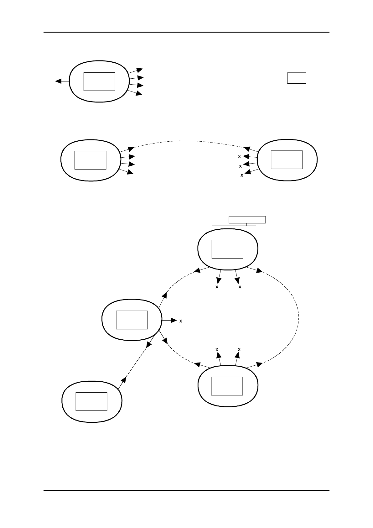
Loops Management
On remote sites, two local outgoing loops (Local user outputs A and B) are activated on the
appearance of a local : equipment alarm or rem ote indication loops 3 and 4 (Local user input #3
or #4).
The remote loopback function allows an equipment named " central site", to register faults
present on remote sites.
This function requires eac h site to transm it to the central site an alarm pres ence m essage. This
messages which corr esponds to remote m onitoring loopback 1 or 2 (Loc al user input #1 or #2)
is transmitted in the S1 byte. To link this mes sage to equipment's alarms, the outputs of the A
and B loops (Local user outputs A and B) should be connected to remote monitoring loops 1 and
2 (Local user input #1 or #2) respectively.
Data chaining in a bus or ring type network architectur e is provided by "OR" f unction validation
between the data received (Far user inputs #1 et #2) via S1 STM1 West and S1 STM1 East, and
local data, for each site in the network.
At the "central site" equipment, "OR" function validation between the data received (Far user
inputs #1 and #2) via S1 STM1 W est and S1 ST M1 East, and loc al data (Local us er input #1 or
#2 and local alarm), enables local alarm loopbacks to be activated (Local user outputs A and B).
To configure the remote loopback function, the f ollowing parameters should be programmed :
"Line remote loopback" and " central site".
The Figure 2-3 gives an exam ple of remote m anagement of the local outgoing loops according
to the equipment connections.
A
EASTEASTWEST WEST
Activation of
Local user
inputs #1 or #2
S1 = state of local user
inputs #1 and #2
Received
West S1
#1
#2
#3
#4
Local
user inputs
AB
Acivation of local
user inputs
folowing activation
of loc a l user
outputs A or B
( équipment
or local user
inputs #3 rt #4)
ADR 155C 2
Local user outputs
#1 or # 2
alarms
S1 = state of local user
inputs #1 and #2
AB
EAST WEST
Acivation of local
user inputs
#1 or #2
folowing activation
#1
#2
#3
#4
Local user
inputs
of loc a l user
outputs A or B
( équipment
alarms
or local user
inputs #3 rt #4)
ADR 155C 3
#1
#2
#3
#4
Local
user inputs
Local user outputs
Local user outputs
B
Figure 2-3 – Remote loopback function (registering alarms on central site)
NOTE : Status of :
- incoming loops (Local user inputs #1 to #4),
- far incoming loops (Far user inputs #1 to #2),
- and outgoing loops (Local user outputs A and B),
may be displayed on HTTP navigator.
No reproduction or communi cation without the written consent of
Installation and User Guide - N56717020101
SAGEM SA
Page A2-11
Page 48

2 - OPERATION
2.5 - Alarms processing
LEDs and pushbuttons
The following tables give the meanings of the lit LEDs and the actions initiated by using the
pushbuttons.
LEDs :
Ö
Monitored
item
Motherboard "ON" Green On In service card
Ethernet "Activity" Green On On reception
(management port Off No traffic
or ADRLAN card) "Link" Yellow On Correct Link
Traffic cards "STATUS" See table below
"STATUS"LEDs on ADR IC 1.x, ADR LAN and ADR 21E120 cards :
Ö
Green LED Red LED Meaning
On Off Card in service and configured
On On Card in service and in alarm
Off Off Hardware default on card (fuse)
Off On Card out of service (not configured)
Flashing Self-test default
Designation Colour Status Meaning
Flashing Self-test default
Off Not powered equipment or not
run software
"ALA M" Red On Major alarm
"ALA m" Yellow On Minor alarm
Off No link
Pushbuttons :
Ö
Designation Location Role Action initiated
"ACK" Front panel Alarm
"INIT
CONFIG"*
* : To activate "INIT", keep button pressed for at least 5 seconds. This button is
inaccessible (and unused) in normal operation. It is neces sary to remove the cover to
access it.
Installation and User Guide - N56717020101
Page A2-12
No reproduction or communi cation without the written consent of
Motherboard Configuration
acknowledge
reload
Pressing disables the outgoing alarm
loops. The visual alarm is kept.
"Factory" Configuration reload
SAGEM SA
Page 49

2 - OPERATION
Defaults and Alarms
The tables below give the default values of severity associated with the failures.
Alarms Description Severity
SPI :
LOS Loss Of Signal- Major
TF Transmit Fail Major
RST :
LOF Loss Of Frame Major
MST :
EBER-B2 Bit Error Rate > 10
SD-B2 Signal Degrade -B2 minor
MS-AIS Alarm Indication Signal Non-alarmed
MS-RDI Remote Defect Indication minor
MSP :
PAM Protection Architecture Mismatch minor
SDH Physical Interface
Regenerator Section Termination
Multiplex section Termination
Multiplex Section Protection
-3
on B2 Byte major
SCM Selector Control Mismatch minor
OTM Operation Type Mismatch minor
MSA :
Multiplex Section Adaptation
AU-AIS Administrative Unit - Alarm Indication Signal Non-alarmed
AU-LOP Administrative Unit – Loss Of Pointer major
HPOM :
Higher Order path Overhead Monitor
HO-RDI/G1 High Order Path -Remote Defect Indication minor
HO-UNEQ High order Path – Unequipped Non-alarmed
HPT :
Higher Order Path Termination
HO-SLM High Order Path -Signal Label Mismatch Non-alarmed
HO-RDI/G1 High Order Path -Remote Defect Indication minor
HO-UNEQ High Order Path –UNEQuipped Non-alarmed
HPA :
Higher Order Path Adaptation
TU-LOM Tributary Unit - Loss Of Multiframe minor
TU-AIS Tributary Unit – Alarm Indication Signal Non-alarmed
TU-LOP Tributary Unit - Loss Of Pointer minor
LPOM :
Lower Order path Overhead Monitor
SD-B3 (VC3) Signal Degrade –B3 minor
SD-B2 (VC12) Signal Degrade –B2 minor
LO-RDI Low order Path -Remote Defect Indication minor
LO-UNEQ Low order Path – Unequipped Non-alarmed
Table 2-9 : Alarms and severity (1/2)
Installation and User Guide - N56717020101
No reproduction or communi cation without the written consent of
SAGEM SA
Page A2-13
Page 50

2 - OPERATION
Alarms Description Severity
LPT :
SD-V5 (VC12) Signal Degrade –V5 minor
SD-B3 (VC3) Signal Degrade –B3 minor
LO-SLM Low order Path – Signal Label Mismatch Non-alarmed
LO-RDI Low order Path – Remote Defect Indication minor
LO-UNEQ Low order Path – Unequipped Non-alarmed
LPA :
LO-SLM Low order Path – Signal Label Mismatch Non-alarmed
PPI :
LOS Loss Of Signal minor
AIS Alarm Indication Signal Non-alarmed
SETS :
T3 LOS Loss Of Signal on T3 sync input minor
Lower order Path Termination
Lower order Path Adaptation
PDH Physical Interface
Synchronous Equipment Timing Source
T1 LOS Loss Of Signal on T1 sync input Non-alarmed
T2 LOS Loss Of Signal on T2 sync input Non-alarmed
T4 - Failure Failure on T4 synchronization output minor
Local equipment
Local user
Remote indication 1 Non-alarmed
inputs # 1
Local user
Remote indication 2 Non-alarmed
inputs # 2
Local user
Remote indication 3 major
inputs # 3
Local user
Remote indication 4 minor
inputs # 4
Remote equipment
Far user inputs
Remote indication 1 Major *
# 1
Far user inputs
Remote indication 2 Minor *
# 2
Others
Message Card configuration major
Message Defective card major
Message Missing card major
Table 2-10 : Alarms and severity (2/2)
* If the equipment configured is declared centre site.
Installation and User Guide - N56717020101
Page A2-14
No reproduction or communi cation without the written consent of
SAGEM SA
Page 51

2 - OPERATION
Correlation of faults
A correlation mechanism is implemented on all faults detected.
This correlation m echanism, implemented on eac h change of information collected, is used to
eliminate faults induced by other faults to facilitate fault finding and fault locating.
The following tables define the faults that are masked for each fault detected in the system..
Key :
X : The fault concerned on the current line is masked by the fault in the current
column.
For example: The LOF fault is masked by fault 2 (LOS).
Correlation of STM1 faults
FAULTS
FAULTS
1
TF2LOS3LOF4AIS
5
SD-B2
6
RDI
1TF
2LOS
3LOF X
4 AIS (MS-AIS) X X
5SD-B2 X X X
6 RDI (MS-RDI) X X X
Correlation of MSP faults
FAULTS
FAULTS
1
PAM
2
SCM
3
OTM
1 PAM
2SCM X
3OTM X
Correlation of AU faults
The AU faults are masked by the STM1 LOS, LOF and AIS (MS-AIS) faults.
The TU-LOM fault is filtered, if there is no configured VC12 connection on this STM1.
FAULTS
FAULTS
1
AU-AIS2AU-LOP
3
UNEQ4RDI5SLM6TU-LOM
1AU-AIS
2AU-LOP
3 UNEQ (VC4 UNEQ) X X
4 RDI (VC4 RDI) X X X
5SLM XXX
6TU-LOM XXX X
Installation and User Guide - N56717020101
No reproduction or communi cation without the written consent of
SAGEM SA
Page A2-15
Page 52

2 - OPERATION
Correlation of TU/VC faults
TU-AIS, LP UNEQ, LP-RDI and LP-SLM are m ask ed by the STM1 LOS, LOF and AIS (MS-AIS)
faults, and by the AU AU-LOP, AU-AIS, UNEQ (VC4 UNEQ) and TU-LOM faults.
TU-LOP is masked by the AU SLM and TU-LOM faults.
Tu-AIS and TU-LOP faults of a not connected input are filtered.
FAULTS
FAULTS
1
TU-AIS2TU-LOP3LP UNEQ4LP-RDI5LP-SLM6LOS7AIS
1TU-AIS
2TU-LOP
3 LP UNEQ X X
4 LP-RDI X X X
5 LP-SLM X X X
Correlation of port faults
FAULTS
FAULTS
1
LOS
2
AIS
1LOS
2AIS X
Correlation of remote faults
LO-REI, LO-RDI, HO-REI and HO-RDI faults of unidirectional connection input are filtered.
Installation and User Guide - N56717020101
Page A2-16
No reproduction or communi cation without the written consent of
SAGEM SA
Page 53

-
2.6
Performance processing
Performance processing consists in supervising the following monitoring ports:
for local equipment:
regeneration section (byte B1) ("
multiplex section (byte B2) ("
VC3 tributary paths ("
VC12 tributary paths (byte V5) ("
near end Low Path Virtual Container
near end working (protection) RS
near end working (protection) MS
"),
near end Low Path Virtual Container
for the remote equipment:
multiplex section (byte M1) ("
VC3 tributary paths ("
VC12 tributary paths (byte V5) ("
far end Low Path Virtual Container
far end working (protection) MS
")
far end Low Path Virtual Container
Performance processing includes the following functions:
2 - OPERATION
"),
"),
"),
"),
").
calculation of the number of errored blocks (or bit errors) on local and remote faults and
monitoring of the appearance f aults over a one second period (VC12-REI indic ators are not
taken into account in the calculation),
calculation and determination of the ES (Err ored Second), SES (Severely Errored Second),
BBE (Background Block Error) and UAS (UnAvailable Second) states for each monitoring
point,
generation for each monitoring point of 15-minute counters and 24- hour counters (BBE, ES,
SES and UAS).
Determination of ES, SES and UAS performance states:
For each of the monitoring points, the following states are:
(Errored Second) : number of seconds with at least one error detected
-ES
in a 1 s period or one fault,
(Severely Errored Second) : number of severely errored seconds,
- SES
An SES is a second for which the number of errors exceeds a defined threshold or
during which at least one fault is detected.
Monitoring point SES declaration threshold
MS (byte B2) (for local) and MS (byte M1) (for remote) 2400
RS (byte B1) (for local) 2400
VC3 (for local) 600
VC12 (byte V5) (for local) 600
(UnAvailable Second) : number of seconds of unavailability,
-UAS
(Background Block Error) : number of residual errored blocks excluding SES.
- BBE
Installation and User Guide - N56717020101
No reproduction or communi cation without the written consent of
SAGEM SA
Page A2-17
Page 54

2 - OPERATION
Generation of 15-minute and 24-hour counters:
The result of these calculations is then aggregated for each of the monitoring points in:
24-hour counters (BBE, ES, SES and UAS),
15-minute counters (BBE, ES, SES and UAS).
The last 6 UNAVAILABLE PERIODS are stored and displayed on HTTP navigator.
The performanc e process is initialized when the equipment is powered up and the monitoring
point is monitored.
The last 16 non-zero 15-minute counters , the current 15-minute counter, the las t non-zero 24-
hour counter, the current 24-hour counter and the las t 6 unavailable periods are displayed on
HTTP navigator.
Installation and User Guide - N56717020101
Page A2-18
No reproduction or communi cation without the written consent of
SAGEM SA
Page 55

2 - OPERATION
2.7 - Procedure for replacing subassemblies
Replacing a card
Remarks:
Alarms appear whenever a card is ex tracted from the subrack. In order to pr event feedback
of M/m alarms and ALA 1 and ALA 2 loops, the card should be declared out of service.
Each module can be extracted or inser ted without acting on other modules or their wiring.
Only the traffic of the concerned module is disturbed.
Procedure:
The procedure described below can apply, unless otherwise specified, to all the cards in the
equipment.
1. Put the card concerned "no service" from HTTP navigator.
2. Remove the external connections performed on the card front side.
NOTE: When the external optical fibers are disconnected, reinstall the protective
covers on connectors.
3. Screw off the TORX screws located on the front side, using the suited screwdriver and
unplug the card
4. Extract the card, complying with the measures of protection against electrostatic discharges.
NOTE: For any card handling, the operator must wear an anti-static bracelet w ell
tight around the wrist and earthed.
5. Package the extracted card in an anti-static bag.
6. Take the new card out of its anti-static bag.
7. Carefully insert the card into its cell, complying with the measures of protection against
electrostatic discharges, and secure it with the TORX screws.
8. Restore connections on the card front side.
NOTE: For the optical STM1 card, remove the protective covers from connectors.
To clean the optical connectors, use a pressurized air aerosol.
9. Configure the card, if necessary, and put it into service.
Replacing the fan module
The ADRFAN module consists of two redundant fans in order to ensure sufficient ventilation
when either of them is defective. Fan failures are detected on the motherboard by monitoring the
power consumed; failures are viewed on "ADR155C shelf view" screen of HTT P navigator: if at
least one fan is faulty, ADRFAN module is framed red (major alarm, not configurable).
NOTE: The operation of ADRFAN is not continuous; its initiation is related to the
equipment internal temperature.
ADRFAN can be extracted, it can be replaced at any moment without disturbing the traffic.
Installation and User Guide - N56717020101
No reproduction or communi cation without the written consent of
SAGEM SA
Page A2-19
Page 56

2 - OPERATION
Procedure:
1. Screw off the TORX screws located on the front side, using the suited screwdriver and
unplug the card.
2. Extract the card, complying with the measures of protection against electrostatic discharges.
NOTE: For any card handling, the operator must wear an anti-static bracelet w ell
tight around the wrist and earthed.
3. Package the extracted module in an anti-static bag.
4. Take the new module out of its anti-static bag.
5 Carefully insert the module into its plac e, com plying with the measures of pr otection against
electrostatic discharges, and secure it with TORX screws
Replacing the front-panel fuse
Procedure:
1. Disconnect the power cable or the 110-240//48V 60W / transf ormer from the primary power
source.
2. Screw off the fuse-holder from the power supply front panel.
3. Replace the defective fuse with an equivalent fuse, namely:
4A quick-break fuse (HA214A)
Dimensions length: 20mm ± 0.5
diameter: 5.2 mm +0.1/-0.2
4. Screw the fuse-holder.
5. Reconnect the power cable or the 110-240//48V 60W/ transformer to the primary power
source
Installation and User Guide - N56717020101
Page A2-20
No reproduction or communi cation without the written consent of
SAGEM SA
Page 57

ADR155C 19" subrack
3 - SPARE PARTS
3. SPARE PARTS
Designation Code no.
ADR155C subrack
Fan module - ADR FAN
Adaptator 22 x 75 ohms 1.0/2.3 19"/ETSI
Traffic card
IC1.1 STM1 optical card - ADR IC1.1 AM101328
IC1.2 STM1 optical card - ADR IC1.2 AM101329
Ethernet 10/100 card - ADR LAN1 AM101331
21 x 2Mbit/s 120 ohms card - ADR 21E120 AM101330
External transformer
Transformer 110-240//48V 60W/ AM101669
Software
AM101333
AM101360
AM101901
Available cable list
Designation Length Code no.
SYNC
Synchronization
Et or ST 21x2 Mbit/s 120 ohms SUBD 2,5 m
21x2 Mbit/s 75 ohms 1.0/2.3
right cable
port
E1 INPUT or E1 OUTPUT
21x2Mbit/s In or Out on motherboard or ADR21E120
No reproduction or communication without the written cons ent of
port
Installation and User Guide - N56715070103
2.5 m
5 m
12 m
25 m
5 m
12 m
25 m
2,5 m
5 m
12 m
25 m
SAGEM SA
251 008 309
251 008 312
251 008 320
251 008 333
55 670 741
55 670 742
55 670 743
55 670 744
55 670 582
55 670 583
55 670 584
55 670 585
Page A3-1
Page 58

3 - SPARE PARTS
Available cable list (continue)
Designation Length Code no
MNGT
P management between two ADR 155C
COMM
VT100 Management port
ETH
Ethernet port on mother board or ADRLAN1 card
LOOPS
Remote indication, remote control and station alarm
loops
POWER
Power supply
TR or REC
FC-PC/FC-PC optical Jumper on ADRIC1.x card
port
port
port
Right cable male – male
Right cable male – male
Crossover cable male – male
Right cable male – female
Right cable male – female
port
port
ports
1,5 m
3 m
1,8 m 4 980 214
1,5 m
3 m
3 m
1,5 m
3 m
2,5 m
5 m
12 m
25 m
1,5 m
3 m
2,5 m
3,4 m
5,8 m
7 m
8,2 m
9,4 m
15 m
20 m
25 m
55 670 655
55 670 656
55 670 421
55 670 422
55 670 610
55 670 423
55 670 424
6 013 628
6 013 261
6 013 161
6 013 262
55 670 796
55 670 797
6 491 366
6 491 367
6 491 369
6 491 370
6 491 371
6 491 372
55 670 481
55 670 495
55 670 752
AUX or EOW
Auxiliary channel and orderwire channel on
ADRIC1.x card
Installation and User Guide - N56715070103
Page A3-2
ports
No reproduction or communication without the written cons ent of
2,5 m
5 m
12 m
25 m
6 013 632
6 013 266
6 013 176
6 013 267
SAGEM SA
Page 59

4 - SPECIFICATIONS
4. SPECIFICATIONS
EQUIPMENT
Optical specifications
Interface type IC1.1 = L1.1 + S1.1 or IC1.2 = L1.2 + S1.2
Bit rate 155.520 Mbit/s ± 20 ppm
Standard ITU-T G.957/G.958
Encoding Not encoded (NRZ)
Optical fiber Single-mode (1 300 nm (IC1.1) or 1 550 nm (IC1.2),
ITU-T G.652)
* : It is possible to use a multi-mode optical fiber
whose diameter is smaller than or equal to 62.5
microns
Guaranteed attenuation 0 - 28 dB with no external attenuator
Typical range 0 - 70 km (IC1.1) or 0 - 100 km (IC1.2)
Connector All-ceramic FC/PC
Mechanical specifications
Height 2U
Width 19" or ETSI
Depth 300 mm
Weight 6 kg approx.
Protection Class (IP) Corresponding to the IP of the rack used
Consumption
< 40 W (to a equipped subrack of two cards
ADR IC1.x and two cards ADR LAN)
Environmental specifications
Mechanical ETS 300 119-4 (19") or CEI 297-3 (ETSI)
ETS 300 019-2-3
Climatic conditions CEI 721-1 (1993)
ETS300 019 part 1-3, class 3.1, 3.2
Operating temperature range - 5 °C à + 45°C
Extended operating temperature
range
Packaged transportation and
storage temperature
Relative humidity < 85%
ESD NF EN 50081-1,
EMC (Electromagnetic Compatibility) NF EN 55022 (1994)
Safety NF EN 60950 and UTE C 92130
Energy ETS 300132-2
- 25 °C to + 55°C (the MTBF [Mean Time Between
Failure] is significantly degraded)
- 40°C to + 70°C
NF EN 50082-1 June 1992
and ETS 300 386-1 1994
+ Additive A1 02/1996 equipment Class B
(the equipment does not provide the fire envelope)
(is VLV equipment)
Installation and User Guide - N56717020101
No reproduction or communi cation without the written consent of
SAGEM SA
Page A4-1
Page 60

4 - SPECIFICATIONS
Predicted reliability *
Motherboard 3.4 10
ADR 21E120 card 0.75 10
ADR1 IC1.x card 2.6 10
ADRLAN1 card 2.25 10
Background 0.33 10
Power supply 1.25 10
ADRFAN Module ** 2.5 10
* The predicted reliability computations ar e based on the CNET's 1993 issue (RDF 93) of the
Reliability Data Manual, on the assumption of specific requirem ents f or the f ollowing: am bient
temperature 25°C (with ventilation conditions such as the subrack internal middle
temperature is less than 40°C), environment (mounted on the ground, f ixed and protected),
qualification, and component ageing. Any changes in the above requirements may entail
variations in the results.
** The fan module does not operate continuously, but only for high ambient temperature.
-6
-6
-6
-6
-6
-6
-6
TRANSFORMER 110-240//48V 60W/ (OPTIONAL)
Dimensions (without cable and connector) L x l x H = 132 mm x 58 mm x 30 mm
Operating temperature 0°C to 40°C
Storage temperature -20°C to 85°C
Input voltage 90 to 264 VAC
Input frequency 47 to 63 Hz
output voltage 48 VDC
Electronics protection Short circuit and overload
Standard EN60950 and UL-CSA
Installation and User Guide - N56717020101
Page A4-2
No reproduction or communi cation without the written consent of
SAGEM SA
Page 61

ANNEX A - CONSTRUCTING AN IP NETWORK ADDRESSING PLAN
A. CONSTRUCTING AN IP NETWORK ADDRESSING PLAN
This annex summarizes the rules for constructing a TMN based on the IP protocols suite.
A.1 - Preamble
The IP protocols suite enables the transport of data in a transmission network in the form of
packets between two points in the network.
According to the ISO model, IP is the network layer protocol. It is therefore responsible f or the
packet routing of each node, so that the packets can be routed correctly via the network.
The protocols "below" IP correspond to the link and physical layers: they set up the links
between two consecutive network nodes.
The protocols "above" IP, TCP and UDP, are the tr ansport layer protocols: they enable end-toend data transmission between two remote points on the network. The protocols based on
TCP/UDP are application oriented: they offer services such as file transfer (TFTP over UDP,
FTP over TCP), equipment management (SNMP), messaging (SMTP), etc...
The figure below describes the stac king of the main protocols that can be used in a network
node.
To download
HTTP Server
HTTP
TCP
ICMP
ARP MAC PPP
mechanism
TFTP
IP
Ethernet
To OS
functions
SNMP
UDP
EOC
IP protocol suite
RIP
Note: T he MAC protocol is linked to the Ethernet physical port (point-multipoint media) and
PPP protocol is linked to the physical ports for the point-to-point link s (optical, radio,
V11 , etc...)
Installation and User Guide - N56717020101
No reproduction or communication without the written cons ent of
SAGEM SA
Page AA-1
Page 62

ANNEX A - CONSTRUCTING AN IP NETWORK ADDRESSING PLAN
A.2 - Addressing IP
To route packets in a node, IP uses an addressing mechanism : depending on the destination
address contained in the packet, it determines by polling its routing table the next router to which
it should send the packet, and determines the physical interface over which it should transmit the
packet. (The terms "router" and "equipment" will be used interchangeably in the following),
There are two, non-exclusive, ways of updating IP routing tables:
• use of static routes entered by operator,
• us e of a routing demon (such as RIP, RIP2, OSPF) which takes charge of dynamic
management of routing tables across the network.
The IP addresses are coded over 4 bytes and are usually represented in decimal form (e.g.:
135.11.33.115). An IP address is divided into 3 fields:
• the "NET" field, on the left,
• the "subnet" field, in the center,
• the "host" field, on the right.
The length of the first field depends on the class to which the addres s belongs. The length of the
"subnet" and "host" fields is defined by a mask associated with the address. T here are three
address classes:
• class A: the "NET" field is coded over the firs t byte; the three other bytes are res erved
for the "SUBNET" and "HOST" fields ; class A addresses vary from 1.0.0.0 to
126.255.255.254,
• class B: the "NET" field is coded over the first two bytes; the two other bytes are
reserved for the "SUBNET" and "HOST" fields ; class B addresses vary from
128.0.0.0 to 191.255.255.254,
• class C: the "NET" field is coded over the f irst three bytes; the last byte is reserved for
the "SUBNET" and "HOST" fields ; class C addresses vary from 192.0.0.0 to
223.255.255.254 ; the maximum number of equipment pieces that can belong to the
same class C IP network (having the same "NET") is 254.
Note: Addresses s tarting with 127 and addresses including "all-1" or "all-0" in the "SUBNET"
and "HOST" fields are not permitted.
Note: The IP standard authorizes that the "SUBNET " and "HOST" fields can be coded over a
number of bits that does not correspond to an byte border; usually this is not
implemented for reasons of address legibility and since the majority of RIP routing
demon implementations do not support this feature.
The "SUBNET" field is defined by a mask which is written in the form: 255.255.255.0,
255.255.0.0, 255.0.0.0, etc : the number of zero bits from the left of the mas k defines the length
of the "HOST" field ; e.g., for the address 40.2.2.2 associated with mask 255.255.255.0, the
"NET" field takes the value 40, the "SUBNET" field the value 2.2 and the "HOST" field the
value 2.
Installation and User Guide - N56717020101
Page AA-2
No reproduction or communication without the written cons ent of
SAGEM SA
Page 63

ANNEX A - CONSTRUCTING AN IP NETWORK ADDRESSING PLAN
A.3 - Addressing plan
A global IP network may be sub-divided into N networks, each with a "NET" number.
Within each network, each physical link (point-to-point or point-multipoint) has its own "SUBNET"
number.
Each equipment connected to this link (2 for point- to-point link, N f or an Ethernet segm ent), has
its own "HOST" number.
Depending on the number of equipm ent pieces and links, address c lasses A, B or C are used
with "SUBNETS" coded over one or two bytes.
To conclude, an IP address and its "SUBNET" mask must be associated with each interface of a
network node.
A.4 - Use of static tables
Concerning the use of static tables, each network node must have its routing table c ompleted in
order for it to be able to route correctly the received packets.
All IP routes of a given equipment routing table contains the following fields:
• "destination @ip" : corresponding to the IP address of the equipment or sub-network (or
network) that is targeted from the equipment in question,
• "subnet mask" : sub-network mask associated with the IP address defined in "destination
@ip"; all equipment pieces with this part of their IP address fields defined by "1" bits
correspond to the "destination @ip" (defined by this same mask) that can be attained us ing
this route,
• "next hop @ip" : IP address of the next router (in direct connection with the equipment in
question) to which the packet is to be sent,
• «m etr ic» (also named «c ost» or dis tance) : value f rom 1 to 15, indic ating the num ber of hops
required to reach the equipment corresponding to the "destination @ip" address. 16
corresponds to infinite for the RIP routing demon. This field m ay only be used by a routing
demon to select a pref erential route if there are several dif ferent possible routes for a given
destination. It is possible to always enter "1" for this field in order to simplif y, if this operation
is not required,
• "interf." : interface number used to r each the nex t r outer ( the IP addres s of which is "next hop
@ip").
Rem : The declaration of interface IP addresses induces the establishment of implicit static
routes to associated SUBNETs. So, it is not necessary to define static routes to join two
equipments of the same SUBNET.
Rem : T he equipment IP addresses are the addres ses of its configured interfaces (or ports).
The manager knows only one IP address per equipment. So, IP address of an
equipment is frequently used to refer to the addres s f illed in the manager database. This
is the address of the port through which the equipment interacts normally with manager.
Rem : To operate an equipment via a PC and an Ethernet interface, it is necessary to change
the IP address of the operating PC for the PC to belong to the same SUBNET as the
Ethernet interface that is used to be connected to the network.
It is advisable to leave HOST 1 number free on eac h SUBNET, i.e., to start numbering
the equipments from HOST 2 number. Thus , the PC will always take an IP address of
this type: NET.SUBNET.1
Installation and User Guide - N56717020101
No reproduction or communication without the written cons ent of
SAGEM SA
Page AA-3
Page 64

ANNEX A - CONSTRUCTING AN IP NETWORK ADDRESSING PLAN
Note: If it is possible to define a default router (option sometimes available), to which any
packet may be transmitted which cannot be routed using the routing table.
The following figure shows an example of an IP network and routing tables ass ociated with two
equipment types. It shall be noted that each port of the onboard routing function corresponds to
a different SUBNET.
Block diagram of example TMN architecture
140.1.0.2
F2
Ethernet
SNMPC
128.1.0.1
128.1.0.2
140.1.0.2 140.1.0.3
F1
Fiber
140.1.1.3
F3
140.1.1.4
F4
Ethernet
Interfaces
NET 128.1
NET 160.1
Ethernet
128.1.0.3
F6
150.1.0.2
Fiber
Ethernet
150.1.1.3
ADR155C F6 Configuration
Ether IP 128.1.0.3
Ether Mask 255.255.0.0
NET 140 - 1
Fiber
SUBNET 150.1.0
150.1.0.3
F7
150.1.1.2
150.1.1.4
F8 F9 F10
SUBNET 150.1.1
NET 150.1
140.1.1.5
F5
150.1.1.5
STM1 IP 150.1.0.2
STM1 Mask 255.255.255.0
X21:P IP 0.0.0.0 (Interface not put into service)
X21:P Mask 0.0.0.0
Static routes
Dest @IP Subnet mask Next hop Interface Metric Remark
140.1.0.0 255.255.0.0 128.1.0.2 e 1 All the NET 140.1
150.1.1.0 255.255.255.0 150.1.0.3 s 1 All the SUBNET 155.1.1
Installation and User Guide - N56717020101
Page AA-4
No reproduction or communication without the written cons ent of
SAGEM SA
Page 65

ANNEX A - CONSTRUCTING AN IP NETWORK ADDRESSING PLAN
ADR155C F8 Modification
Interfaces
Ether IP 150.1.1.3
Ether Mask 255.255.255.0
STM1 IP 0.0.0.0 (Interface not put into service)
STM1 Mask 0.0.0.0
X21:P IP 0.0.0.0 (Interface not put into service)
X21:P Mask 0.0.0.0
Static routes
Dest @IP Subnet mask Next hop Interface Metric Remark
128.1.0.0 255.255.0.0 150.1.1.2 e 2 All the NET 128.1
140.1.0.0 255.255.0.0 150.1.1.2 e 3 All the NET 140.1
150.1.0.0 255.255.255.0 150.1.1.2 e 1 All the SUBNET 155.1.0
A.5 - Use of RIP routing demon
"RIP" is a routing demon which makes it possible to dispense with part of the static routing
tables.
The network mus t be divided into "AUTONOMOUS SYSTEMS" or "AS", each with a different
"NET" number.
Each AS is an RIP routing domain and must be lim ited to a length of 15 hops m ax. between two
equipment pieces requiring to exchange pack ets within this AS. T he m axim um distanc e is tak en
into account to include the worst case security.
These ASs are mutually independent (within RIP), and are linked via isolated networks each
constituting a single link (Ethernet or point-to- point). Each isolated network has its own "NET"
number.
The equipment interfac es belonging to an isolated network must be filtering ( RIP filtering option
activated on these interfaces), i.e., they prohibit export of automatic updates of RIP routing
tables. These equipment pieces with a filtering interface are designated "border".
Within an AS, all equipment pieces must have their RIP routing demon activated.
Within each AS, each link between two equipment pieces is des cribed by a specific "SUBNET"
value.
The routings from one AS to another AS, via an isolated network, are described using static
routes.
In the example given above, "NET" 128.1 corresponds to an isolated network and "NETs" 160.1
and 150.1 correspond to ASs in which RIP is activated.
Installation and User Guide - N56717020101
No reproduction or communication without the written cons ent of
SAGEM SA
Page AA-5
Page 66

ANNEX A - CONSTRUCTING AN IP NETWORK ADDRESSING PLAN
Installation and User Guide - N56717020101
Page AA-6
No reproduction or communication without the written cons ent of
SAGEM SA
Page 67

MULTIPLEXEUR ADD-DROP
à 155 Mbit/s COMPACT
ADR 155C
Guide d'Installation et d'Utilisation
Guide d'Installation et d'Utilisation - N56717020101
Reproduction et communication interdites sans autorisation écrit e de
SAGEM SA
Page B0-1
Page 68

NIVEAUX DE SECURITE DES ACCES
Niveau de sécurité des accès du châssis 19"
Les connecteurs sont repérés sur les faces avant de l'équipement (carte-mère et modules).
Connecteurs Fonction Niveau de
sécurité
PWRA/PWRB Accès alimentation TBTS
PWR Accès alimentation TBTS
Carte-mère
SYNC Accès de synchronisation 2 Mbit/s G.703 TBTS
E1 INPUT & E1 OUTPUT Accès de trafic 2 Mbit/s G.703 TBTS
MNGT Accès d'interconnexion avec d'autres équipements TBTS
COMM Accès de gestion locale via une console au standard
VT100 ou un PC
ETH Accès de gestion distante via un réseau Ethernet TBTS
LOOPS Accès boucles sèches et télésignalisations TBTS
Carte ADR ICI 1.x
TR et REC Accès optique STM-1 IC1.1 ou IC1.2 G.957 et G.958 Laser classe 1
Sans danger
EOW et AUX Accès voie de service TBTS
Carte ADR LAN1
ETH Accès Ethernet TBTS
Carte ADR 21E120
E1 INPUT & E1 OUTPUT Accès de trafic 2 Mbit/s G.703 TBTS
1
TBTS
)
Le châssis 19" ne doit être monté que dans des baies ou bâtis dont la partie
inférieure est fermée ou équipée d'un filtre à air classé V1 ou HF1 au
minimum, ou reposant sur un sol non inflammable.
Obligation de terre sûre
Ce matériel ne peut être installé que par un personnel compétent. Sa conformité est
conditionnée au raccordement de la borne de terre de protection à une terre sûre de résistance
Z < 5 ohms.
)
Précaution de manipulation : Toute intervention à l'intérieur des équipements
nécessite obligatoirement l'utilisation d'un bracelet électrostatique.
Pile au Lithium
)
Attention : il y a danger d'explosion, s'il y a remplacement incorrect de la pile.
Remplacer uniquement avec une batterie de mêm e type ou d'un type équivalent
recommandé par le constructeur
Mettre au rebut les batteries usagées conformément aux instructions du fabricant
Dans l'ADR155C, le remplacement de la pile ne peut être effectué que par retour SAV.
1
Circuit à Très Basse Tension de Sécurité
Guide d'Installation et d'Utilisation - N56717020101
Page B0-2
Reproduction et communication interdites sans autorisation écrit e de l a
SAGEM SA
Page 69

TABLE DES MATIERES
REPERTOIRE DES MISES A JOUR 0-2
SECTION A : Installation and user guide...................... A0-1 to AA-6
SECTION B: Guide d'installation et d'utilisation............. B0-1 à BA-6
NIVEAUX DE SECURITE DES ACCES B0-2
TABLE DES MATIERES B0-3
1. INSTALLATION ET MISE EN SERVICE ...............................................................B1-1 à B1-28
1.1 - Généralités B1-1
1.2 - Installation du châssis B1-3
1.3 - Raccordement des accès B1-4
1.3.1 - Raccordement de l'alimentation B1-4
1.3.2 - Raccordements sur la carte-mère B1-7
1.3.3 - Raccordement sur le module ADR IC1.x B1-13
1.3.4 - Raccordement sur le module ADR LAN1 B1-16
1.3.5 - Raccordement sur le module ADR 21E120 B1-17
1.3.6 - Bandeau de raccordement 75 Ω B1-18
1.4 - Mise en service B1-20
1.4.1 - Configuration nécessaire B1-22
1.4.2 - Paramétrage de la fonction communication B1-22
1.4.3 - Utilisation du navigateur HTTP B1-26
Figure 1-1- Installation du châssis ADR155C B1-2
Figure 1-2 - Raccordement des accès alimentation B1-5
Figure 1-3 - Raccordement des accès sur la carte-mère B1-6
Figure 1-4 - Raccordement sur le module ADR IC1.x B1-12
Figure 1-5 - Raccordement sur le module ADR LAN1 B1-16
Figure 1-6 - Raccordement sur le module ADR 21E120 B1-17
Figure 1-7 - Bandeau de raccordement 75 Ω B1-18
Figure 1-8 - Processus de mise en service d’un réseau d’ADR155C B1-19
Figure 1-9 - Exemples de configuration de la fonction de communication B1-21
Figure 1-10 - Arborescence des menus B1-27
2 . EXPLOITATION ....................................................................................................B2-1 à B2-20
2.1 - Présentation fonctionnelle B2-1
2.2 - Généralités B2-2
2.3 - Paramètres d'exploitation B2-2
2.4 - Fonctions prédéfinies B2-9
2.5 - Traitement des alarmes B2-12
2.6 - Traitement de la qualité B2-18
2.7 - Procédures de changement de sous-ensemble B2-20
Guide d'Installation et d'Utilisation - N56717020101
Reproduction et communication interdites sans autorisation écrit e de
SAGEM SA
Page B0-3
Page 70

Figure 2-1 - Synchronisation à partir de l'entrée de synchronisation externe à 2 MHz (T3) B2-10
Figure 2-2 - Synchronisation à partir d'un accès à 2 Mbit/s B2-10
Figure 2-3 - Déport de boucles (Rapatriement des alarmes sur un site central) B2-11
Tableaux 2-1 à 2-6 - Paramètres de configuration B2-2 à B2-7
Tableaux 2-7 et 2-8 - Commandes B2-8 à B2-9
Tableaux 2-9 à 2-11 : Alarmes et gravité..................................................................B2-13 à B2-15
3. RECHANGES..........................................................................................................B3-1 à B3-2
4. CARACTERISTIQUES TECHNIQUES ...................................................................B4-1 à B4-2
A. CONSTRUCTION DU PLAN D'ADRESSAGE D'UN RESEAU IP..........................BA-1 à BA5
A.1 - Préambule BA-1
A.2 - Adressage IP BA-2
A.3 - Plan d’adressage BA-3
A.4 - Utilisation des tables statiques BA-3
A.5 - Utilisation du démon de routage RIP BA-5
Guide d'Installation et d'Utilisation - N56717020101
Page B0-4
Reproduction et communication interdites sans autorisation écrit e de l a
SAGEM SA
Page 71

1 - INSTALLATION ET MISE EN SERVICE
1. INSTALLATION ET MISE EN SERVICE
1.1 - Généralités
L’ ADR 155C est un multiplexeur add-drop optique ST M-1 qui perm et de construir e des liais ons
point à point STM-1, des anneaux STM-1 ou des réseaux maillés, avec protection de conduit
(SNC) ou de ligne (MSP), réalisant ainsi le transport de liaisons à 2 Mbit/s, Ethernet, STM-1.
L’ ADR 155C peut être utilisé en :
Multiplexeur terminal STM-1 avec une capacité maximale de 63 VC12 et possibilité de
protection 1+1,
Répéteur STM-1, aptitude à régénérer 2 VC4,
Multiplexeur STM1 à insertion/extraction avec une capacité maximale de 4 STM-1 et
insertion/extraction de 21 VC12
Point d’interconnexion de LAN (en fonction exclusive jusqu’à 3 liais ons déportées totalisant 3
VC3 utilisés).
Cet équipement est géré à partir d'un navigateur HTTP :
soit localement, via son interface Ethernet dédiée
soit à distance par téléexploitation
ou à partir du gestionnaire de réseau IONOS-ANM ; dans ce dernier cas, l'utilisation du
protocole SNMP permet également la supervision globale du réseau.
L'utilisation d’un terminal local avec émulation VT100 es t néces s air e lors de la pr emière mise
en service pour la configuration des paramètres de communication.
Les raccordements du réseau de gestion s'effectuent via les DCC D1 à D3 (ou D4 à D12)
des STM1 ou sur les interfaces Ethernet (ETH) ou P (MNGT) de l'équipement
L'ADR155C prend place dans des baies 19" ou bâtis ETSI. Il est constitué :
d'un châssis 2U équipé d'une carte-m ère regroupant les fonctions de base de l'équipement,
d'un fond de panier et d'une alimentation 48V DC sécurisée,
d'un module ADRFAN, composée de deux blocs de ventilation redondants,
de quatre cartes d’accès au choix :
carte d’accès STM1 optique IC1.1 ou IC1.2 (c arte ADR IC1.1 ou ADR IC1.2) permettant
une connexion VC4 ou 3 connexions VC3 ou 63 connexions VC12 ou un mixte de
connexions VC3/VC12
carte d'accès 21 x 2 Mbit/s G.703 (carte ADR21E120), permettant 21 connexions VC12
carte d'accès Ethernet 10/100 (carte ADR LAN1), permettant 2 connexions VC3.
Guide d'Installation et d'Utilisation - N56717020101
Reproduction et communication interdites sans autorisation écrit e de
SAGEM SA
Page B1-1
Page 72

1 - INSTALLATION ET MISE EN SERVICE
B
A
V
P
D
76,2 mm
Montan ts ga uc h es
ADR 155C
CHASSIS 19"
2U
de la baie
6
(
6<
(28
<1
1&
&
2873
C
M
Châssis ADR 155C
ADR 155C
bâti ETSI
76,2 mm
738
87
7
2U
6
(
6<
(28
<1
2873
1&
738
&
87
7
2
2 vis HS
1
M6x12
2 écrous
cage M6
Montage en baie 19"
Figure 1-1- Installation du châssis ADR155C
Guide d'Installation et d'Utilisation - N56717020101
Page B1-2
Reproduction et communication interdites sans autorisation écrit e de
1
2 écrous
cage M6
Montage en bâti ETSI
SAGEM SA
2
2 vis HS
M6x12
Page 73

1 - INSTALLATION ET MISE EN SERVICE
1.2 - Installation du châssis
Le châssis ADR 155C peut s'installer en baie 19" ou en bâti ETSI (voir Figure 1-1). Il est
constitué :
d'une carte-mère située dans sa partie inférieure (repère M),
de quatre alvéoles banalisées (repères A à D), destinées à recevoir les cartes d'accès,
d'un tiroir situé à gauche du châssis destiné à recevoir le module de ventilation (repère V),
d'une alimentation (repère P).
Tous les raccordem ents s'effec tuent en face avant, soit sur le bandeau du châssis, soit sur
les modules eux-mêmes.
Installation en baie 19"
Les éléments de fixation du châssis en baie 19" (équerres, écrous cage et vis de fixation),
sont fournis dans son emballage.
L'ADR155C possède un système de régulation thermique par ventilation ; lors de
l'installation, prévoir un espace suffisant pour la prise d'air à gauche du châss is et un pour
l'évacuation d'air en haut à droite du châssis. Par ailleurs, ne pas gêner la convection
naturelle d'air sur le flanc droit.
Procéder aux opérations suivantes :
prévoir un emplacement de 2U dans la baie pour chaque équipement et un es pacement de
1U entre les équipements,
fixer les équerres de fixation pour montage en baie 19" de chaque côté du châssis,
clipser de chaque côté de la baie deux écrous cage M6 (repère 1),
présenter l'arrière du châssis 19" face à la baie,
faire glisser le châssis 19" j usqu'à c e que les équerr es de f ixation entr ent en c ontact avec les
montants, face aux 4 écrous cage, puis le fixer au m oyen de 4 vis à tête hexagonale M6x12
(repère 2).
Installation en bâti ETSI
L'installation du châssis en bâti ETSI est identique à celle en baie 19".
Dans ce cas, utiliser le jeu d'équerres de fixation spécifique d'un montage en bâti ETSI.
Implantation des cartes
RAPPEL : Avant toute intervention sur les cartes, l'opérateur doit se munir d'un bracelet
antistatique.
Les alvéoles d'un ADR155C sont banalisées. Cependant pour faciliter le c âblage et garantir
l'homogénéité des sites il est recommandé de procéder de la façon suivante :
positionner les cartes affluents depuis l'alvéole C dans le sens des aiguilles d'une montre
positionner les cartes rés ultants depuis l'alvéole D dans le sens inver se des aiguilles d'une
montre
vérifier la présence du module de ventilation dans son tiroir réservé,
Fixer chaque carte au moyen des vis de type Torx de type M3 (étoile à 6 branches) en
utilisant un tournevis adapté.
Guide d'Installation et d'Utilisation - N56717020101
Reproduction et communication interdites sans autorisation écrit e de
SAGEM SA
Page B1-3
Page 74

1 - INSTALLATION ET MISE EN SERVICE
1.3 - Raccordement des accès
Les raccordements à effectuer sur l'équipement sont fonction de la configuration choisie :
Sur la carte d'alimentation :
accès d'alimentation : "
PWR
" ou "
PWRA
" et/ou "
PWRB
",
Sur le bandeau de la carte-mère du châssis :
accès de gestion : "
accès de télésignalisation, de télécommandes et d'alarmes station "
accès de synchronisation 2Mbit/s G.703 "
accès de trafic 21x2Mbit/s G.703 "
COMM
ETH" et/ou "MNGT
", "
E1 INPUT
SYNC
" et "
"
".
E1 OUTPUT
".
LOOPS
".
Selon les modules d’accès utilisés
accès STM-1 optiques et accès des voies de service,
accès Ethernet
accès de trafic 21x2Mbit/s G.703.
Règles de raccordement
Ö
Pour une bonne répartition des cordons de part et d'autre du châssis, les racc ordem ents des
alvéoles A et C, les 21 accès 2Mbit/s et l'accès de synchronisation sont orientés vers la
gauche. Tous les autres raccordements sont orientés vers la droite.
Ö
Le passage des cordons ne doit pas gêner l'extraction d'un module ; en particulier, les
câbles de raccordement de la moitié gauche du châssis doivent être assujettis au bâti
avec un mou suffisant afin de permettre l'extraction du module de ventilation lors
d'une opération de maintenance.
1.3.1 - Raccordement de l'alimentation
.Accès "PWRA" et/ou "PWRB", lorsque l'équipement est alim enté à partir d'une (ou deux)
source(s) - 48 V, la (ou les) sources(s) d'alimentation doit (doivent) être limitée(s) à 100 VA.
.Accès "PWR" lorsque l'équipement est alimenté à partir d'une tension réseau (230 V CA),
via un transformateur 110-240//48V 60W/ optionnel.
Règles de raccordement à respecter :
Ö
Les accès d'alimentation "PWR" et "PWRA" et/ou "PWRB" peuvent être connectés
simultanément.
Ö
Le cordon d'alim entation ou le transform ateur 110-240//48V 60W / ne doit pas être relié à la
source primaire avant d'être raccordé à l'équipement.
Ö
Le transf ormateur 110-240//48V 60W / doit être m onté éloigné de toute source de chaleur et
aucune traction ne doit être exercée sur ses fils de raccordement.
Guide d'Installation et d'Utilisation - N56717020101
Page B1-4
Reproduction et communication interdites sans autorisation écrit e de
SAGEM SA
Page 75

1 - INSTALLATION ET MISE EN SERVICE
Description des accès d'alimentation
POWER
- 48V
2A MAX
"PWR"Connecteur de type Jack
Fusible F4A L250 V fusible rap ide 4A
faible pouvoir de coupure
250V
PWRA et PWRB
1 - 48 B1
5
9
6
1
2 - 48 B1 6 OB1
3 - Réservé 7 OB1
4 - 48 B2 8 OB2
5 - 48 B2 9 OB2
ADR-155C
Figure 1-2 - Raccordement des accès alimentation
Interface d'alimentation "PWRA"/"PWRB" :
Tension d'entrée : Une ou deux sources d'alimentation - 48 V de type TBTS (Très
Basse Tension de Sécurité)
Plage de tension autorisée : - 36 V à - 60 V
Plage de tension maximale : - 36 V à - 72 V
Puissance 100 VA maximum
Connecteur HE5 9 points mâle
5
9
N° de broche Désignation du signal
1 -48B1
6OB1
2 -48B1
7OB1
3 Réservé
8OB2
4 -48B2
9OB2
5 -48B2
1
6
NOTA : Le blindage du connecteur est relié à la masse de l'équipement
Interface d'alimentation "PWR" :
Accès Raccordement du transformateur 110-240//48V 60W/
Connecteur Jack (âme = OB1 et blindage = - 48 V1).
Guide d'Installation et d'Utilisation - N56717020101
Reproduction et communication interdites sans autorisation écrit e de
SAGEM SA
Page B1-5
Page 76

1 - INSTALLATION ET MISE EN SERVICE
"SYNC"
5
9
1 : GND
2 : TX1_TIP 6 : TX1_RING
3 : RX1_TIP 7 : RX2_TIP
4 : RX2_RING 8 : RX1_RING
5 : RESERVED 9 : RESERVED
1
6
LOOPS
8
15
1 : Break B
2 : Make B 9 : Common B
3 : Common A 10 : Break A
4 : Gnd 11 : Make A
5 : R-MON 4 N 12 : R-MON 4 P (OB)
6 : R-MON 3 N 13 : R-MON 3 P (OB)
7 : R-MON 2 N 14 : R-MON 2 P (OB)
8 : R-MON 1 N 15 : R-MON 1 P (OB)
Schéma de principe
d'une boucle sèche au repos
M
CB
1
9
"E1 OUTPUT" et "E1 INPUT"
15 1
30
44 31
1 : Tx(Rx) 1A
2 : Tx(Rx) 3B
3 : Tx(Rx) 4A
4 : Tx(Rx) 6B
5 : Tx(Rx) 7A
6 : Tx(Rx) 9B
7 : Tx(Rx) 10A
8 : Tx(Rx) 12B
9 : Tx(Rx) 13A
10 : Tx(Rx) 15B
11 : Tx(Rx) 16A
12 : Tx(Rx) 18B
13 : Tx(Rx) 19A
14 : Tx(Rx) 21B
15 : GND
16 : GND
17 : Tx(Rx) 2B
18 : Tx(Rx) 3A
19 : Tx(Rx) 5B
20 : Tx(Rx) 6A
21 : Tx(Rx) 8B
22 : Tx(Rx) 9A
23 : Tx(Rx) 11B
24 : Tx(Rx) 12A
25 : Tx(Rx) 14B
26 : Tx(Rx) 15A
27 : Tx(Rx) 17B
28 : Tx(Rx) 18B
29 : Tx(Rx) 20B
30 : Tx(Rx) 21A
31 : Tx(Rx) 1B
32 : Tx(Rx) 2A
33 : Tx(Rx) 4B
34 : Tx(Rx) 5A
35 : Tx(Rx) 7B
36 : Tx(Rx) 8A
37 : Tx(Rx) 10B
38 : Tx(Rx) 11A
39 : Tx(Rx) 13B
40 : Tx(Rx) 14A
41 : Tx(Rx) 16B
42 : Tx(Rx) 17A
43 : Tx(Rx) 19B
44 : Tx(Rx) 20A
"MNGT"
5
9
1 : GND
2 : RXPA 6 : RXPB
3 : TXPA 7 : TXPB
4 : TXCLKPA 8 : TXCLKPB
5 : RXCLKPA 9 : RXCLKPB
1
6
Figure 1-3 - Raccordement des accès sur la carte-mère
16
COMM
5
9
1 : DCD
2 : RX 6 : DSR
3 : TX 7 : RTS
4 : DTR 8 : CTS
5 : Gnd 9 : NC *
Voyant vert "ON"
carte en service
Allumé
Clignotant
Eteint
ou logiciel non démarré
Bouton-poussoir
acquittement des alarmes
défaut autotest
équipement non alimenté
Voyants "ALA"
Voyant rouge "M"
allumé : alarme majeure
Voyant jaune "m"
allumé : alarme mineure
"ACK"
ETH
Contact 8Contact 1
1 : TX_ETH_TIP 5 : NC
2 : TX_ETH_RING 6 : RX_ETH_RING
3 : RX _ETH _TIP 7 : NC
4 : NC * 8 : NC
1
6
Voyant jaune
Allumé : liaison correcte
Voyant vert
Allumé
NC * : Réservé
: état de la liaison
: état du trafic
: réception en cours
Guide d'Installation et d'Utilisation - N56717020101
Page B1-6
Reproduction et communication interdites sans autorisation écrit e de
SAGEM SA
Page 77

1 - INSTALLATION ET MISE EN SERVICE
1.3.2 - Raccordements sur la carte-mère
1.3.2.1 - Accès de télésignalisation, de télécommande et d'alarmes
station ("LOOPS")
Interface "LOOPS" :
Accès 4 entrées de télésignalisation (
Local user inputs
polarisées au - 48 V en interne, actives à l'état fermé et à isolation galvanique
(courant de boucle compris entre 1 et 10 mA),
2 sorties de boucle sèche (commun, repos et travail) (
utilisées comme alarme station ou télécommande (courant maximal = 100mA
sur charge résistive),
Connecteur Type HE5 - 15 points femelles.
8
15
N° de broche Désignation du signal Remarques
1 BREAK B Contact repos de la boucle sèche B
9 COMMON B Contact com mun de la boucle sèche B
2 MAKE B Contact travail de la boucle sèche B
10 BREAK A Contact repos de la boucle sèche A
3 COMMON A Contact commun de la boucle sèche A
11 MAKE A Contact travail de la boucle sèche A
4 GND Masse
12 R- MON 4 P (OB) Boucle de télésignalisation N°4
5R-MON 4 N
13 R- MON 3 P (OB) Boucle de télésignalisation N°3
6R- MON 3 N
14 R- MON 2 P (OB) Boucle de télésignalisation N°2
7R- MON 2 N
15 R- MON 1 P (OB) Boucle de télésignalisation N°1
8R- MON 1 N
1
9
) pour contacts flottants,
Local user outputs
)
NOTA : OB est le "OU" logi que des signaux OB1 et OB2 des interfaces al i mentation "PWR", "PWRA" et "PWRB".
Interface "ETH" :
Accès Interface Ethernet de gestion fonctionnant à 10 Mbit/s en mode half duplex ou
full duplex selon le mode utilisé par l’interlocuteur (adaptation dynamique du port
Ethernet à chaque nouvelle connexion de l’interlocuteur),
Connecteur Type RJ48 (RJ45 blindé).
Contact 1
N° de broche Désignation du signal Remarques
1 TX_ETH_TIP Sortie Ethernet (point chaud)
2 TX_ETH_RING Sortie Ethernet (point froid)
3 RX_ETH_TIP Entrée Ethernet (point c haud)
4 NC Réservé
5 NC Réservé
6 RX_ETH_RI NG Entrée Et hernet (point froid)
7 et 8 NC Réservé
Contact 8
vue de face
Guide d'Installation et d'Utilisation - N56717020101
Reproduction et communication interdites sans autorisation écrit e de
SAGEM SA
Page B1-7
Page 78

1 - INSTALLATION ET MISE EN SERVICE
NOTA : Deux LEDs sont associées au connecteur "ETH" :
• LED, de couleur verte, "Activity" : indicateur de l'état du trafic,
• LED, de couleur jaune, "Link" : indicateur de l'état de la liaison.
1.3.2.2 - Accès de gestion et d'exploitation
Interface "COMM" :
Accès Interface RS232, interconnexion d’une console ou émulation au
standard VT100
Débit 19200 bauds (8 bits de données, pas de bit de parité et 1 bit de
stop),
Connecteur Type HE5 – 9 points femelles
5
9
N° de broche Désignation du signal Remarques
1 DCD Relié à DSR
6 DSR Poste de données prêt (Data Set Ready) (vers E T CD)*
2 RX Réception de données (vers ETCD)*
7 RTS Demande pour émettre (Request To Send) (de ETCD)*
3 TX Emission de données (de ET CD)*
8 CTS Prêt à émet tre (Clear To Send) (vers ETCD)*
4 DTR Terminal de données prêt (Data Terminal Ready) (de E T CD)*
9 RI Ring Indicator (non connecté)
5 GND Masse
1
6
* L'ADR155C est vue comme un ETCD
Câble de raccordement Voir schéma ci-dessous.
Côté équipement
"COMM"
Connecteur HE5
9 points mâles
Schéma de cablage
1
6
9
5
Côté VT100 ou PC
Connecteur HE5
9 points femelles
1
6
9
5
Guide d'Installation et d'Utilisation - N56717020101
Page B1-8
Reproduction et communication interdites sans autorisation écrit e de
SAGEM SA
Page 79

1 - INSTALLATION ET MISE EN SERVICE
)
Interface "MNGT" :
Accès synchrone V.11 (différentiel) Interconnexion possible avec
d’autres équipements SAGEM ADR155C, FOT 155C, à travers
des liens synchrones série utilisés en mode codirectionnel à 64
kbit/s ou contra-directionnel maître (rythme défini par l’ADR
155C)
Débit 64 kbit/s,
Connecteur Type HE5 - 9 points femelles.
5
9
1
6
N° de broche Désignation
du signal
1 GND Masse (non connecté)
6RXPB(+)
2 RXPA (-)
7TXPB(+)
3 TXPA (-)
8 TXCLKPB (+)
4 TXCLKPA (-)
9 RXCLKPB (+)
5 RXCLKPA (-)
Polarité Remarques
Entrée données reçues sur l'interface P et éc hantillonnées sur le
front montant de l'horloge de réception RXCLKP (B-A)
Sortie données émises sur l'interface P sur le f ront descendant
de l'horloge d'émission TXCLKP (B -A)
Sortie * horloge d'émission ; en mode codirectionnel, le rythme
de l'horloge d'émission est issu du rythme interne de
l'équipement
Entrée horloge de réception
*En mode contradirectionnel esclave (entrant) les signaux TXCLK sont des entrées.
Chronogramme de l'interface "MNGT" en mode codirectionnel (utilisation synchrone 64
kbit/s) :
TXCLKP (B-A)
(sortie horloge d'émission
codirectionnelle)
TXP (B-A)
(sortie données émises
sur l'interface P)
B8 B1 B2
RXCLKP (B-A)
(entrée horloge de réception)
RXP (B-A)
(entrée données reçues
sur l'interface P
B8 B1 B2
Guide d'Installation et d'Utilisation - N56717020101
Reproduction et communication interdites sans autorisation écrit e de
SAGEM SA
Page B1-9
Page 80

1 - INSTALLATION ET MISE EN SERVICE
1.3.2.3 - Accès de synchronisation 2 Mbit/s G.703
Interface "SYNC"
Accès 2 Interfaces d'entrée de synchronisation externe à 2 MHz G.703
(T3) et une interface de sortie de synchronisation à 2 MHz
G.703 (T4) Conforme à la recommandation G.703 de l'UIT-T (§
10.3 pour l'interface d'entrée, § tab.10 pour l'interface de sortie)
Débit 2,048 Mbit/s ± 50 ppm,
Impédance 120 Ω symétrique,
Connecteur HE5 9 points femelles (120 Ω).
5
9
N° de broche Désignation du signal Remarques
1 GND Terre
6 TX1 RING (T4-) Sortie T4-1 (point froid)
2 TX1 TIP (T4+) Sortie T4-1 (point chaud)
7 RX2 TIP (T3+) Entrée T3-2 (point chaud)
3 RX1 TIP (T3+) Entrée T3-1 (point chaud)
8 RX1 RING (T3-) Entrée T3-1 (point froid)
4 RX2 RING (T3-) Entrée T3-2 (point froid)
9 NC Réservé
5 NC Réservé
1
6
NOTA : Le blindage du connecteur est relié à la masse électrique de la face avant du châssis
1.3.2.4 - Accès de trafic 21 x 2 Mbit/s G.703
Accès "E1 INPUT" et "E1 OUTPUT" :
Accès Accès de trafic 21 x 2 Mbit/s Conforme à la recommandation
G.703 de l'UIT-T (§ 6.3 pour l'interface d'entrée, § tab.6 pour
l'interface de sortie)
Débit 2,048 Mbit/s ± 50 ppm,
Code HDB3,
Impédance 120 Ω symétrique,
Connecteur SUB D haute densité 44 points femelles supportant le câble
L907
(21 accès).
Deux connecteurs sont associés aux accès : les appellations (RX) correspondent à celles du
connecteur E1 INPUT et les appellations (TX) à celles du connecteur E1 OUTPUT.
15
30
44 31
1
16
Guide d'Installation et d'Utilisation - N56717020101
Page B1-10
Reproduction et communication interdites sans autorisation écrit e de
SAGEM SA
Page 81

1 - INSTALLATION ET MISE EN SERVICE
N° de broche
16
31
1
17
2
32
18
33
3
19
4
34
20
35
5
21
6
36
22
37
7
23 11
8
38
12
24
39
9
25 14
10
40
15
26
41
11
27
12
42
28
13
43
29
14
44
30
15
Accès Désignation du signal
GND
1
2
3
4
5
6
7
8
9
10
13
16
17
18
19
20
21
TX(RX) 1B
TX(RX) 1A
TX(RX) 2B
TX(RX) 2A
TX(RX) 3B
TX(RX3A
TX(RX) 4B
TX(RX) 4A
TX(RX) 5B
TX(RX) 5A
TX(RX) 6B
TX(RX) 6A
TX(RX) 7B
TX(RX) 7A
TX(RX) 8B
TX(RX) 8A
TX(RX) 9B
TX(RX) 9A
TX(RX) 10B
TX(RX) 10A
TX(RX) 11B
TX(RX) 11A
TX(RX) 12B
TX(RX) 12A
TX(RX) 13B
TX(RX) 13A
TX(RX) 14B
TX(RX) 14A
TX(RX) 15B
TX(RX) 15A
TX(RX) 16B
TX(RX) 16A
TX(RX) 17B
TX(RX) 17A
TX(RX) 18B
TX(RX) 18A
TX(RX) 19B
TX(RX) 19A
TX(RX) 20B
TX(RX) 20A
TX(RX) 21B
TX(RX) 21A
GND
Remarques
Masse
Sortie (Entrée) 2 Mbit/s (point chaud)
Sortie (Entrée) 2 Mbit/s (point froid)
Sortie (Entrée) 2 Mbit/s (point chaud)
Sortie (Entrée) 2 Mbit/s (point froid)
Sortie (Entrée) 2 Mbit/s (point chaud)
Sortie (Entrée) 2 Mbit/s (point froid)
Sortie (Entrée) 2 Mbit/s (point chaud)
Sortie (Entrée) 2 Mbit/s (point froid)
Sortie (Entrée) 2 Mbit/s (point chaud)
Sortie (Entrée) 2 Mbit/s (point froid)
Sortie (Entrée) 2 Mbit/s (point chaud)
Sortie (Entrée) 2 Mbit/s (point froid)
Sortie (Entrée) 2 Mbit/s (point chaud)
Sortie (Entrée) 2 Mbit/s (point froid)
Sortie (Entrée) 2 Mbit/s (point chaud)
Sortie (Entrée) 2 Mbit/s (point froid)
Sortie (Entrée) 2 Mbit/s (point chaud)
Sortie (Entrée) 2 Mbit/s (point froid)
Sortie (Entrée) 2 Mbit/s (point chaud)
Sortie (Entrée) 2 Mbit/s (point froid)
Sortie (Entrée) 2 Mbit/s (point chaud)
Sortie (Entrée) 2 Mbit/s (point froid)
Sortie (Entrée) 2 Mbit/s (point chaud)
Sortie (Entrée) 2 Mbit/s (point froid)
Sortie (Entrée) 2 Mbit/s (point chaud)
Sortie (Entrée) 2 Mbit/s (point froid)
Sortie (Entrée) 2 Mbit/s (point chaud)
Sortie (Entrée) 2 Mbit/s (point froid)
Sortie (Entrée) 2 Mbit/s (point chaud)
Sortie (Entrée) 2 Mbit/s (point froid)
Sortie (Entrée) 2 Mbit/s (point chaud)
Sortie (Entrée) 2 Mbit/s (point froid)
Sortie (Entrée) 2 Mbit/s (point chaud)
Sortie (Entrée) 2 Mbit/s (point froid)
Sortie (Entrée) 2 Mbit/s (point chaud)
Sortie (Entrée) 2 Mbit/s (point froid)
Sortie (Entrée) 2 Mbit/s (point chaud)
Sortie (Entrée) 2 Mbit/s (point froid)
Sortie (Entrée) 2 Mbit/s (point chaud)
Sortie (Entrée) 2 Mbit/s (point froid)
Sortie (Entrée) 2 Mbit/s (point chaud)
Sortie (Entrée) 2 Mbit/s (point froid)
Masse
NOTA : Le blindage du connecteur est relié à la masse électrique de la face avant du châssis
Guide d'Installation et d'Utilisation - N56717020101
Reproduction et communication interdites sans autorisation écrit e de
SAGEM SA
Page B1-11
Page 82

1 - INSTALLATION ET MISE EN SERVICE
ADR IC1
STATUS
STATUS
Voyants STATUS
Vert Rouge
Allumé Eteint Carte en service
Allumé Allumé Carte en alarme
Eteint Eteint Défaut matériel de la carte (fusible)
Eteint Allumé Carte hors service
Clignotant Défaut autotest
TR REC
TR REC
Accès STM1 émission
Accès STM1 réception
AUXEOW
AUXEOW
"
et "
"
et "
EOW
EOW
81
15
1 : NC
2 : TA 9 : TB
3 : TOF PA 10 : TOF PB
4 : RA 11 : RB
5 : ROF PA 12 : ROF PB
6 : R64 A 13 : R64 B
7 : T64 A 14 : T64 B
8 : GND 15 : NC
AUX
AUX
"
"
9
ADR IC1.1
STATUS
Voyants STATUS
Vert Rouge
Allumé Eteint Carte en service
Allumé Allumé Carte en alarme
Eteint Eteint Défaut matériel de la carte (fusible)
Eteint Allumé Carte hors service
Clignotant Défaut autotest
EOW AUX
Version 1
Accès STM1 émission
Accès STM1 réception
TR REC
"
et "
AUX
"
9
EOW
81
15
1 : NC
2 : TA 9 : TB
3 : TOF PA 10 : TOF PB
4 : RA 11 : RB
5 : ROF PA 12 : ROF PB
6 : R64 A 13 : R64 B
7 : T64 A 14 : T64 B
8 : GND 15 : NC
Version 2
Figure 1-4 - Raccordement sur le module ADR IC1.x
Guide d'Installation et d'Utilisation - N56717020101
Page B1-12
Reproduction et communication interdites sans autorisation écrit e de
NC : Réservé
SAGEM SA
Page 83

1 - INSTALLATION ET MISE EN SERVICE
1.3.3 - Raccor dement sur le module ADR IC1.x
Chaque module ADR IC1.x permet de raccorder :
un accès STM1 (un accès émission "TR" et un accès réception "
deux voies de service à 64 kbit/s (appelées "EOW" et "AUX") qui par défaut sont
transportées respectivement dans les octets E1 et F1 du SOH
1.3.3.1 - Raccordement des accès STM1
Retirer le connecteur protège contacts,
Raccorder les accès STM-1 sur les connecteurs FC/PC de face avant :
Ö
Emission Connecteur TR
Ö
Réception Connecteur REC
Accès "TR" et "REC" :
Type d'interface : IC 1.1 = L 1.1 + S 1.1 ou IC 1.2 = L 1.2 + S 1.2,
Débit : 155,520 Mbit/s ± 15 ppm,
Norme : UIT-T G.957/G.958,
Codage : Non codé (NRZ),
Fibre optique* : monomode (1300 nm (IC1.1) ou
1550 nm (IC1.2), UIT-T G.652),
REC
")
Puissance émise : -5 à 0 dBm
Puissance reçue maximum : 0 dBm
-10
Sensibilité à 10
Atténuation garantie : 0 - 28 dB sans atténuateur externe,
Portée typique : 0 - 60 km (IC1.1) ou 0 - 90 km (IC1.2),
Connecteur : FC/PC tout céramique
* : Il est possible d'utiliser une fibre optique multi-m ode, de diamètre inférieur ou égal à 62,5
microns. Le budget optique est alors r éduit à 25 % du budget optique obtenu avec une fibre
mono-mode. La f ibre optique émission est de type mono-mode et la f ibre optique réception
est de type multi-mode.
: - 34 dB
1.3.3.2 - Raccordement des voies de service,
Interface "EOW" et "AUX" :
Accès synchrone V.11 (différentiel),
Débit 64 kbit/s,
Guide d'Installation et d'Utilisation - N56717020101
Reproduction et communication interdites sans autorisation écrit e de
SAGEM SA
Page B1-13
Page 84

1 - INSTALLATION ET MISE EN SERVICE
9
)
Connecteur Type HE5 - 15 points femelles.
81
15
N° de broche Désignation
du signal
1 - Non connecté
9TB(+)
2 TA (-)
10 TOFPB (+)
3 TOFPA (-)
11 RB (+)
4 RA (-)
12 ROFPB (+)
5 ROFPA (-)
13 R64B (+)
6 R64A (-)
14 T64B (+)
7 T64A (-)
15 - Non connecté
8 Masse
Pola-
rité
Remarques
Entrée données à transmettre sur la trame STM-1 et
échantillonnées sur le front mont ant de l'horloge T64 (B-A)
Sortie synchro octet en ém iss ion indiquant le positi onnement du bit
1 et émise sur le front montant de l'horloge T64 (B-A)
Sortie données extraites de la tram e STM-1 et émises s ur le front
descendant de l'horloge R64 (B-A)
Sortie synchro octet en réc eption i ndiquant l e posi tionnem ent du bit
1 et émise sur le front descendant de l'horloge R64 (B-A)
Sortie horloge de réception à 64 kHz
Sortie horloge d'émiss i on à 64 kHz
Chronogramme de l' interface "EO W /AUX " en mode c ontra-direc tionnel (utilisation s ynchrone
64 kbit/s) :
T64 (B-A)
(sortie horloge d'émission)
T (B-A)
(entrée données à transmettre
sur la ligne STM1)
TOFP (B-A)
(sortie synchro octet
en émission)
R64 (B-A)
(sortie horloge de réception)
R (B-A)
(sortie données reçues
de la ligne STM1)
ROFP (B-A)
(sortie impulsion de trame
en réception
B8 B1 B2
B8 B1 B2
Guide d'Installation et d'Utilisation - N56717020101
Page B1-14
Reproduction et communication interdites sans autorisation écrit e de
SAGEM SA
Page 85

1 - INSTALLATION ET MISE EN SERVICE
1.3.3.3 – Raccordement avec exploitation MSP
Les accès EOW et AUX étant physiquement solidaires des modules ADR IC1.x, l'exploitation
des voie de service et voie auxiliaire avec protection MSP nécessite l'utilisation d'un cordon
en Y reliant électriquement un à un à l'identique les signaux des connecteurs EOW et AUX.
EOW
ADR IC1.x Working
EOW
ADR IC1.x Prot ection
Cordon en Y
pour exploitation
de la voie de service
TRTRREC
REC
AUX
AUX
Cordon en Y
pour exploitation
de la voie auxilia ir e
De même pour garantir un bon compor tement lors du basculement d'un m odule sur l'autre,
l'opérateur doit veiller à conserver une conf iguration identique s ur les deux c artes ADR IC1.x
; un message d'avertissement apparaît en cas de modification.
Seules les connexions ne sont pas identiques. Il ne doit pas y avoir de connexions sur le
module en "Protection" toutes les connexions étant créées sur le module "Working".
Guide d'Installation et d'Utilisation - N56717020101
Reproduction et communication interdites sans autorisation écrit e de
SAGEM SA
Page B1-15
Page 86

1 - INSTALLATION ET MISE EN SERVICE
1.3.4 - Raccordement sur le module ADR LAN1
ADR LAN1
/
10
STATUS
Voyants STATUS
Vert Rouge
Allumé Eteint Carte en service
Allumé Allumé Carte en alarme
Eteint Eteint Défaut matériel de la carte (fusible)
Eteint Allumé Carte hors service
Clignotant Défaut autotest
ETH
100 HALF/FULL
HALF/FULL
Voyant jaune :
Ethernet
(Half ou Full Duplex)
Allumé : Full duplex
nature de l'interface
ETH
1 : TX_ETH_TIP 5 : NC
2 : TX_ETH_RING 6 : RX_ETH_RING
3 : RX _ETH _TIP 7 : NC
4 : NC 8 : NC
Voyant jaune
Allumé : Liaison correcte
Voyant vert
Allumé : Réception en cours
: Etat de la liaison
: Etat du trafic
Contact 8Contact 1
NC : Réservé
10/100
Voyant jaune :
Ethernet
Allumé : 100 Mbit/s
débit sur l'interface
Figure 1-5 - Raccordement sur le module ADR LAN1
Interface "ETH" :
Accès Interface Ethernet de trafic fonctionnant à 10 ou 100 Mbit/s en
mode half duplex ou full duplex selon le mode utilisé par
l’interlocuteur (adaptation dynamique du port Ethernet à chaque
nouvelle connexion de l’interlocuteur),
Connecteur Prise Ethernet 10 ou 100 BaseT - Type RJ48 (RJ45 blindé).
Contact 8Contact 1
vue de face
N° de broche Désignation du signal Remarques
1 TX_ETH_TIP Sortie Ethernet (point chaud)
2 TX_ETH_RING Sortie Ethernet (point froid)
3 RX_ETH_TIP Entrée Ethernet (point chaud)
4 NC Réservé
5 NC Réservé
6 RX_ETH_RI NG Entrée Et hernet (point froid)
7 et 8 NC Réservé
NOTA : Deux LEDs sont associées au connecteur "ETH" :
• LED, de couleur verte, "Activity" : indicateur de l'état du trafic,
• LED, de couleur jaune, "Link" : indicateur de l'état de la liaison.
Caractéristiques électriques conformes à l'IEEE 802.3U
Guide d'Installation et d'Utilisation - N56717020101
Page B1-16
Reproduction et communication interdites sans autorisation écrit e de
SAGEM SA
Page 87

1 - INSTALLATION ET MISE EN SERVICE
1.3.5 - Raccor dement sur le module ADR 21E120
Les raccordements de traf ic à 2 Mbit/s ef f ec tués sur les acc ès "
E1 INPUT"
"E1 OUTPUT"
et
la carte ADR21E120 sont identiques à ceux effectués sur les accès "
"E1 OUTPUT"
Voyants
Vert Rouge
Allumé Eteint Carte en service
Allumé Allumé Carte en alarme
Eteint Eteint Défaut matériel de la carte (fusible)
Eteint Allumé Carte hors service
Clignotant Défaut autotest
de la face avant de la carte-mère (voir § 1.3.2.4)
ADR 21E120
STATUS
E1 OUTPUT E1 INPUT
STATUS
"E1 OUTPUT" et "E1 INPUT"
15 1
30
44 31
1 : Tx(Rx) 1A
2 : Tx(Rx) 3B
3 : Tx(Rx) 4A
4 : Tx(Rx) 6B
5 : Tx(Rx) 7A
6 : Tx(Rx) 9B
7 : Tx(Rx) 10A
8 : Tx(Rx) 12B
9 : Tx(Rx) 13A
10 : Tx(Rx) 15B
11 : Tx(Rx) 16A
12 : Tx(Rx) 18B
13 : Tx(Rx) 19A
14 : Tx(Rx) 21B
15 : GND
16 : GND
17 : Tx(Rx) 2B
18 : Tx(Rx) 3A
19 : Tx(Rx) 5B
20 : Tx(Rx) 6A
21 : Tx(Rx) 8B
22 : Tx(Rx) 9A
23 : Tx(Rx) 11B
24 : Tx(Rx) 12A
25 : Tx(Rx) 14B
26 : Tx(Rx) 15A
27 : Tx(Rx) 17B
28 : Tx(Rx) 18B
29 : Tx(Rx) 20B
30 : Tx(Rx) 21A
E1 INPUT"
16
31 : Tx(Rx) 1B
32 : Tx(Rx) 2A
33 : Tx(Rx) 4B
34 : Tx(Rx) 5A
35 : Tx(Rx) 7B
36 : Tx(Rx) 8A
37 : Tx(Rx) 10B
38 : Tx(Rx) 11A
39 : Tx(Rx) 13B
40 : Tx(Rx) 14A
41 : Tx(Rx) 16B
42 : Tx(Rx) 17A
43 : Tx(Rx) 19B
44 : Tx(Rx) 20A
de
et
Figure 1-6 - Raccordement sur le module ADR 21E120
Guide d'Installation et d'Utilisation - N56717020101
Reproduction et communication interdites sans autorisation écrit e de
SAGEM SA
Page B1-17
Page 88

1 - INSTALLATION ET MISE EN SERVICE
1.3.6 - Bandeau de raccordement 75 Ω
Rédaction réservée
Figure 1-7 - Bandeau de raccordement 75
Guide d'Installation et d'Utilisation - N56717020101
Page B1-18
Reproduction et communication interdites sans autorisation écrit e de
ΩΩ
SAGEM SA
Page 89

1 - INSTALLATION ET MISE EN SERVICE
TEST LOCAL
Inventaire du matériel
Contrôle des alimentation - 48 V
Bouclage optique des résultants
Insertion des paramètres de communication (VT100)
* cas d'un équipement
unitaire sous équipé
Mise à l'heu re et insertion de la conf i guration de test des accès afflue nts
Contrôle de continuité des accès affluents
Contrôle de redondan ce du - 48 V
Contrôle des alarmes et des boucles A et B
Test local de la transm ission (30 mn) *
Raccordement de l'entrée de synchronisation
externe d'un équipement "maître" (o ptionnel)
non
(navi g at eu r H T T P )
Raccordement optique
Elaborati on de la configu ra t i on
Test local du dernier
équipement sur le réseau ?
oui
Mise en liaison
Mesures opt iques
Vérifica tion de la protection MSP
Raz des compteurs
Qualité 24 H en liaison
Equipement opérationnel
(constitution du doss ier d'installation)
Sauvegarde de la configuration
Figure 1-8 - Processus de mise en service d’un réseau d’ADR155C
Guide d'Installation et d'Utilisation - N56717020101
Reproduction et communication interdites sans autorisation écrit e de
SAGEM SA
Page B1-19
Page 90

1 - INSTALLATION ET MISE EN SERVICE
1.4 - Mise en service
NOTA
: L'exploitation de l'équipement peut être réalisée à partir d'un PC équipé d'une émulation
VT100 et du navigateur HTTP ; sa configuration minimale est définie au paragraphe 1.4.1.
Un terminal local avec émulation VT100 est indispensable lors de la première mise en
service, afin de pouvoir accéder à l'équipement via la fonction de gestion ; toutefois, celui-ci
ne permet que le paramétrage de la fonction communication
Procédure.
)
A la première mise en service, l'équipement scrute sa constitution et la prend comme
configuration attendue, en service, non monitoré. Il est donc conseillé d'insérer toutes les
cartes d'accès avant la mise sous tension afin d'accélérer la mise en service.
)
Mettre en marche l'alimentation raccordée à l'équipement.
)
L'équipement effectue des auto-tests :
lorsque les auto-tests se sont déroulés correctement, le voyant "ON" est allumé,
dans le cas contraire, un code de clignotement du voyant définit l'auto-test défaillant
(contacter la hotline).
)
Paramétrer l'interface de communication à l'aide de la VT100 (voir § 1.4.1).
)
A l'aide du navigateur HTTP, (voir § 1.4.3).
Mettre à jour l'heure et la date de l'équipement
Mettre chaque carte d'accès sous surveillance : valider la commande "Monitoring".
)
Raccorder les accès 2 Mbit/s et/ou Ethernet, selon la constitution de l'équipement,
)
Raccorder le s accès AUX et EOW nécessaires.
)
Télécharger une configuration prédéfinie ou élaborer la configuration souhaitée à l'aide du
navigateur HTTP :
Créer les connexions
Etablir les sécurisations souhaitées (protection MSP, protection SNC ..)
Choisir la source de synchronisation et modifier ses paramètres si nécessaire.
Modifier si nécessaire les paramètres de surveillance et la configuration des alarmes
La configuration par défaut des différents paramètres est donnée au § 2.1.1.
)
Effectuer les tests des liaisons STM-1 en respectant le processus décrit à la Figure 1-8.
)
L'équipement est dès lors opérationnel.
)
Les alarmes d'exploitation peuvent signaler un mauvais r accordement des acc ès. Vérifier le
raccordement des accès, les alarm es qui corr espondent aux accès r accordés et corr iger les
problèmes éventuels.
)
Effectuer une sauvegarde de la configuration
REMARQUE : Il est possible, une fois la mise en service effectuée, de raccorder des accès
supplémentaires 2 Mbit/s G.703, Ethernet ou STM1 et d'insérer ou d'extraire des
cartes sous tension.
Guide d'Installation et d'Utilisation - N56717020101
Page B1-20
Reproduction et communication interdites sans autorisation écrit e de
SAGEM SA
Page 91

1 - INSTALLATION ET MISE EN SERVICE
T
HTP
E
T
H
R
SN PM
P
P
P
Fonction de communication sur un ADR 155C
D1 - D3 sur STM1 D1 - D3 sur STM1
HT PT
E
T
H
R
SN PM
P
P
P
Exemple 1 : communication sur une liaison point à point d'ADR 155C
Accès de gestion
Accès ETH
.
4 accès PPP
.
(Point to Point Protocole)
x
x
x
Application
Serveur HTTP
.
Agent SNNP pour
.
IONOS ANM
R
Fonction
de
routage
HT PT
P
P
P
R
SN PM
E
T
H
Le "TPI" peut se brancher sur une
interface Ethernet quelconque dès
lors que le paramètrage permet
d'atteindre 1 équipement à exploiter
ADR
* Il faut IONOS ANM pour
exploiter ce FOT C
(mais on peut exploiter
l'ADR depuis l'interface
ETH du FOT C)
FOT C *
E
T
H
R
SN PM
E
T
H
P
P
P
HT PT
R
SN PM
- D3
D
1
sur Résultant
STM1
P
P
P
- D3
D
1
sur Affluent
STM1
D1 - D3 sur
STM1 Est
D1 - D3 sur
STM1 Ouest
S
N
M
P
D1 - D3
sur STM1
Ouest
- D3
D
1
sur STM1
Est
S
N
M
P
IONOS ANM
HT
E
R
PPP
PPP
R
HTE
H
T
T
P
- D3
D
1
sur STM1
Est
- D3
D
1
sur STM1
Ouest
H
T
T
P
ADR
ADR
Exemple 2 : communication sur un anneau d'ADR 155C et de FOT 155C
Figure 1-9 – Exemples de configuration de la fonction de communication
Guide d'Installation et d'Utilisation - N56717020101
Reproduction et communication interdites sans autorisation écrit e de
SAGEM SA
Page B1-21
Page 92

1 - INSTALLATION ET MISE EN SERVICE
1.4.1 - Configuration nécessaire
La configuration minimale proposée pour le PC d'exploitation est la suivante :
Description Configuration 1 Configuration 2
Processeur Pentium à 266 MHz
Mémoire 32 Mo 64 Mo
Affichage 800x600, 256 couleurs (conseillé 1024x768)
Interface Interface série RS232
Carte réseau Ethernet 10 base T
Système d'exploitation Windows 95 Windows NT4
Applications Hyperterminal pour Windows
Navigateur HTTP : Netscape Communicator 4.5
1.4.2 - Paramétrage de la fonction communication
La Figure 1-9 présente les ressources disponibles et dif férentes configurations possibles de la
fonction de communication;
)
Raccorder l'accès "
COMM
" de l'équipement à un port "COM" non utilisé du PC avec
émulation VT100,
)
Mettre le PC sous tension,
)
Lancer l'application Hyper Terminal
Lors de la première utilisation, procéder comme suit:
raccorder l'accès "
mettre le PC sous tension,
sélectionner, successivement, dans le bureau de Windows les boutons de commande
COMM
" de l'équipement à un port "COM" non utilisé du PC,
Démarrer, Programmes, Accessoires et HyperTerminal,
choisir l'icône représentative de l'application HyperTerminal,
une fenêtre de description de la connexion apparaît ; donner un nom et choisir une icône
pour la connexion et valider vos choix,
une nouvelle fenêtre apparaît ; choisir le port "COM" du PC qui est raccordé à
l'équipement et valider votre choix,
une nouvelle fenêtre apparaît ; configurer les paramètres du port comme indiqué ci-
dessous et valider la programmation :
. Bits par seconde : 19200,
. Bits de données : 8,
. Parité : aucun,
. Bits d'arrêt : 1,
. Contrôle du flux : aucun,
enregistrer la connexion (commande Enregistrer du menu Fichier de l'application).
NOTA
: Lors de la prochaine ouverture de l'application "Hyperterminal", il suf fira de choisir
l'icône de la connexion pour se connecter sur l'équipement.
A la mise sous tension de l'équipement, le menu d'exploitation apparaît.
Pour quitter l'application "Hyperterminal", sélectionner la commande Quitter du menu Fichier.
Guide d'Installation et d'Utilisation - N56717020101
Page B1-22
Reproduction et communication interdites sans autorisation écrit e de
SAGEM SA
Page 93

1 - INSTALLATION ET MISE EN SERVICE
)
Ouvrir une session et entrer votre mot de passe (pour paramétrer la fonction de
communication, il est indispensable de disposer des droits "supervisor")
NOTE : par défaut, lors de la première mise en service, le mot de passe est vide.
)
Le menu ci-dessous apparaît :
Pour sélectionner une commande, taper le numéro de la com mande dans la zone de texte
"Choice ?" et appuyer sur la touche "ENTER" pour valider votre choix.
)
Choix "1" : Configuration des interfaces de communication,
Guide d'Installation et d'Utilisation - N56717020101
Reproduction et communication interdites sans autorisation écrit e de
SAGEM SA
Page B1-23
Page 94

1 - INSTALLATION ET MISE EN SERVICE
L'écran présente les 5 interfaces de comm unication possibles avec leurs carac téristiques et
propose de modifier chacune d'elles tour à tour. Ces interfaces sont :
- un accès Ethernet –ETH
- 4 accès PPP (Point to Point Protoc ole) – PPP1 à PPP4 - à choisir parmi les c hemins de
gestion suivants :
soit aux octets D1 à D3 du canal DCC1 d'une trame STM1 (appelés DCC1-A, DCC1-B,
DCC1-C ou DCC1-D selon le nombre et la position des modules ADR IC1.x dans
l'équipement) ,
soit l'interface MNGT
Chaque interface est définie par ses caractéristiques:
- "Port" : port physique "ETH", "PPP1" à "PPP4"
- "Admin" ou état de l'interface : "ON" (interface active) ou "OFF" (interface non active)
- "@ IP" : adresse IP
- "subnet mask" : masque de sous-réseau
- "@ IP of dest" : adresse IP du destinataire (pour les ports PPP uniquement)
- "Path" : chemin de gestion choisi pour les ports PPP (DCC1x ou MNGT)
- "RIP" : autoadaptativité du routage de gestion à la structure du réseau validée ou non
(limitée à 16 bonds sans passerelle)
La sauvegarde du paramétrage s'effectue port par port.
)
Choix "2" : Configuration des routes statiques,
L'écran visualise les routes de gestion déjà définies avec leurs caractéristiques :
- "No" : référence de la route
- "destination @ IP" : adresse IP du destinataire (équipement ou sous-réseau)
- "subnet mask" : masque de sous-réseau
- "next hop @ IP" : adresse IP de l'équipement suivant (connecté en direct avec
l'équipement donné)
- "interface" : interface utilisée pour atteindre l'équipement suivant
- "cost" : ou "metric", nombre de bonds pour atteindre le destinataire.
Guide d'Installation et d'Utilisation - N56717020101
Page B1-24
Reproduction et communication interdites sans autorisation écrit e de
SAGEM SA
Page 95

1 - INSTALLATION ET MISE EN SERVICE
A partir de cet écran, il est possible de m odifier les routes existantes, de les supprim er ou
d'en créer de nouvelles (le routage statique est nécessair e si des FOT155C sont présents
dans le réseau ou pour une interconnexion avec un sous-réseau voisin).
)
Choix "3" : Affichage des informations de routage,
Cet écran permet de visualiser la table de routage, de lister les routes dynamiques et/ou
statiques ainsi que la configuration des interfaces
)
Choix "4" : REBOOT de l'équipement,
Cette commande perm et d'eff ectuer un REBOO T im m édiat de l'application et de redémar rer
avec les paramètres déjà mémorisés dans l'équipement
)
Choix "5" : Logout / Déconnexion
Le paramétrage terminé, cette commande ferme la session en cours
Une sortie de session automatique est effectuée après quelques minutes de non activité
(délai paramétrable à partir du gestionnaire).
Guide d'Installation et d'Utilisation - N56717020101
Reproduction et communication interdites sans autorisation écrit e de
SAGEM SA
Page B1-25
Page 96

1 - INSTALLATION ET MISE EN SERVICE
1.4.3 - Utilisation du navigateur HTTP
1.4.3.1 - Première mise en service
Lancer l'application NESCAPE
Dans l'écran d'accueil, renseigner le champ "Adresse" avec l'adresse IP de l'équipement
ADR155C
ATTENTION
: Avec NESCAPE 4.5, l'adresse IP de l'équipement ne doit pas c omporter de '0'
non significatif. Exemple : "http://135.11.9.30/" au lieu de "http://135.11.09.30/".
L'écran d'accueil du navigateur "Welcome on the ADR155C's site" apparaît.
Lors de la première m ise en service, le mot de passe est vide ; c liquer sur
accéder à l'écran "ADR155C shelf view"
Le navigateur est dès lors, opérationnel.
1.4.3.2 - Présentation du navigateur
A l'ouverture d'une session sur le navigateur HT TP, l'écran "ADR155C s helf view" r eprésente la
vue globale de l'équipement, où chaque alvéole est repérée par une lettre A, B, C, D ou M
conformément à la Figure 1-1.
Apply
pour
Cet écran permet de visualiser l'état de l'équipement, en particulier :
les incohérences entre configuration et constitution : chaque alvéole com porte le nom de la
carte attendue (haut, gauche) et le nom de la carte insérée (au milieu, en rouge, si
nécessaire),
les modules en alarme, encadrés en rouge dans le c as d'une alarm e m aj eure, en jaune pour
une alarme mineure,
les modules configurés hors surveillance sont représentés en grisé.
Les modules configurés hors service comportent une croix pour signaler cet état
administratif.
Guide d'Installation et d'Utilisation - N56717020101
Page B1-26
Reproduction et communication interdites sans autorisation écrit e de
SAGEM SA
Page 97

1 - INSTALLATION ET MISE EN SERVICE
Cet écran permet également :
d'activer les fonctionnalités communes de l'équipement telles que la synchronisation, la
sécurité, les inform ations de trafic, etc en cliquant sur une fonc tion de la bar r e de menu ; voir
arborescence du menu général Figure 1-10 .
d'accéder aux fonctionnalités liées à un module en partic ulier (par exem ple, protection MSP
dans le cas d'un module ADRIC1.x) : double click sur le module à sélec tionner, la flèche de
sélection clignote et son menu spécifique apparaît ; voir arborescence des menus "carte"
Figure 1-10
de visualiser les caractér istiques propres à un accès (connexions ef fectuées, configuration
de celles-ci, état des alarmes ...) en sélectionnant le connecteur correspondant.
Pour chaque fonction visualisée, les paramètres de configuration, les commandes
d'exploitation, les paramètres ac tifs et l'état des alarm es sont regroupés sur le mêm e écran,
les différentes actions possibles étant accessibles ou non à l'opérateur selon son niveau
d'habilitation.
Le bord supérieur de la fenêtre du navigateur rappelle l'adresse IP de l'équipement le niveau
d'habilitation acquis et, si besoin, l'alvéole concernée.
LOGIN
EQUIPMENT
Date and Time
Inventories
(hardware/Software)
Security
Management
Upload and
Download
Menu "ADR21E120"
Maintenance
Monitoring
Service
Expected Card
Performance :
VC12 Near (#1 to 21)
VC12 Far (# 1 to 21)
Board status
E1 INPUT/OUTPUT ports
TRANSMISSION
Failure hold off/on
time
Laser
VC12 Near / VC12 Far
SYNCHRONISATION
Synchronisation
sources
Menu "ADRIC1.x"
Maintenance
Monitoring
Service
Expected Card
Performance :
VC3 Near / VC3 Far
RST Near
MST Near / MST Far
Protection
Board status
TR /REC ports
EOW port
AUX port
CROSS-
CONNECTION
Configuration
Delete
Names
modifications
LAN Wizard
Menu "ADRLAN1"
Monitoring
Service
Expected Card
Performance :
VC3 Near / VC3 Far
Board status
ETH port
EVENT LOGS
Clear
Refresh
Convert
Save
Menu "CARTE-MERE"
Maintenance
Monitoring
Performance :
VC12 Near (# 1 to 21)
VC12 Far (# 1 to 21)
IP Parameters
Board status
E1 INPUT/OUTPUT ports
About
Help
?
Figure 1-10 - Arborescence des menus
Guide d'Installation et d'Utilisation - N56717020101
Reproduction et communication interdites sans autorisation écrit e de
SAGEM SA
Page B1-27
Page 98

1 - INSTALLATION ET MISE EN SERVICE
Guide d'Installation et d'Utilisation - N56717020101
Page B1-28
Reproduction et communication interdites sans autorisation écrit e de
SAGEM SA
Page 99

2 - EXPLOITATION
2. EXPLOITATION
2.1 - Présentation fonctionnelle
L'ADR 155C est un multiplexeur add-drop optique ST M1 qui permet de construire des liaisons
point à point STM1, des anneaux STM1 ou des réseaux maillés, en r éalisant, ainsi le déport de
liaisons à 2 Mbit/s, Ethernet ou STM1.
L'ADR 155C peut aussi être raccordé à un équipem ent de la hiérarchie numérique synchrone
conforme aux recommandations G.707 et G.783 de l'UIT-T.
La modélisation de l'ADR 155C en blocs fonc tionnels selon la norme G.783 est présentée c iaprès :
SPI : Interface P hysique synchrone
RST : Terminaison de sec tion de régénération OHA : Accès au surdébit
MST : Terminaison de section de multiplexage
MSP : Protection de sec tion de multiplexage
SETS : Source de rythme de
MSA : Adaptation de sect i on de multiplexage
HPOM : Surveillance de préfixe de conduit d'ordre supérieur
HPC : Connexion de conduit d'ordre supérieur
HPT : Terminaison de conduit d'ordre supérieur
HPA : Adaptation de conduit d'ordre supérieur
LUG : Générateur de conduit d'ordre d'ordre inféri eur non équi pé
LPOM : Surveillance de préfixe de conduit d'ordre i nférieur MCF : Fonction de
LPC : Connexion de conduit d'ordre inférieur
LPT : Terminaison de conduit d'ordre inférieur
LPA Adaptation de conduit
d'ordre inférieur (VC12)
PPI : Interface physique
plésiochrone (VC12)
Adaptation de conduit
d'ordre inférieur (VC3)
Interface physique
plésiochrone (VC3)
l'équipement synchrone
SETPI : Interface physique
de synchronisation de
l'équipement synchrone
SEMF : Fonction de gestion
d'équipement synchrone
communicati on de message
Guide d'Installation et d'Utilisation - N56717020101
Reproduction et communication interdites sans autorisation écrit e de
SAGEM SA
Page B2-1
Page 100

2 - EXPLOITATION
2.2 - Généralités
L'exploitation et la maintenance de l'ADR 155C sont réalisées:
- soit directement sur l'équipement, au moyen des voyants de la face avant et des deux
boucles de gestion technique (boucles A et B),
- soit à partir d'un PC équipé d'un navigateur HTTP,
- soit à partir d'un gestionnaire de réseau par l'utilisation du protocole SNMP.
2.3 - Paramètres d'exploitation
Les paramètres d'exploitation regroupent :
les paramètres de configuration,
les commandes ou opérations de maintenance (ces actions sont effacées en cas de perte de
l'alimentation)
les alarmes et leur sévérité.
Paramètres de configuration
NOTA : La dénomination des blocs fonctionnels, les paramètres de configuration et leur valeur
par défaut, notés "
XXXXXX
", sont visualisés sur le navigateur HTTP.
Paramètres de configuration en fonction des blocs fonctionnels Valeur par
défaut
SPI : Interface physique SDH (SDH Physical Interface)
La fonction coupure automatique du Laser est toujours activée
(fonctionnalité globale à l'équipement)
ALS
"
" (Automatic Laser Shutdown) "
enable
"
MST : Terminaison de section de multiplexage (Multiplex section Termination)
Surveillance de l'EBER-B2 ; configurable en "
Monitoring
"
Monitoring
" ou "
No
Monitoring
"
"
Lorsque EBER-B2 n'est pas surveillé, les actions conséquentes AIS, SF et
MS-RDI sont inhibées
Seuil SD-B2 : configurable de 10-6 à 10
SD-B2 threshold
"
"
-9
-6
10
"
"
MSP : Protection de section de multiplexage (Multiplex Section Protection)
Type de liaison : 1+0 ou 1+1
1+0
"
"
Mode de sécurisation : bidirectionnel / unidirectionnel
Mode
"
"
BIDIR
"
"
Autorisation de réversibilité : retour après une durée WTR sur la liaison
normal lorsque le défaut (SF ou SD) ayant entraîné la commutation a
disparu
Revertive
"
"
Tableau 2-1 – Paramètres de configuration (1/6)
Guide d'Installation et d'Utilisation - N56717020101
Page B2-2
Reproduction et communication interdites sans autorisation écrit e de l a
SAGEM SA
OFF
"
"
 Loading...