


 Loading...
COMPACT 155 Mbit/s
ADD-DROP MULTIPLEXER
MULTIPLEXEUR ADD-DROP
à 155 Mbit/s COMPACT
ADR 155C
Installation and User Guide
Guide d'Installation et d'Utilisation
N56717020101
Issue : April 2000
Edition : Avril 2000
COMPACT 155 Mbit/s
ADD-DROP MULTIPLEXER
MULTIPLEXEUR ADD-DROP
à 155 Mbit/s COMPACT
ADR 155C
Installation and User Guide
Guide d'Installation et d'Utilisation
N56717020101
Issue : April 2000
Edition : Avril 2000
LIST OF CHANGES
REPERTOIRE DES MISES A JOUR
(A new edition replaces any previous versions)
(Une nouvelle édition annule et remplace la précédente)
No/N° |
Date/Date |
Change description/Description de la |
Page/Page |
|
|
mise à jour |
|
|
|
|
|
0101 |
April 2000/ |
Creation of original user guide/ |
All pages/ |
|
Avril 2000 |
Création du document à l'édition originale |
Toutes pages |
|
|
|
|
|
|
|
|
|
|
|
|
|
|
|
|
Remarque importante : La version logicielle actuelle n'offre pas la fonction RIP décrite dans ce guide.
Important remark : The current software version does not offer the RIP function described in this guide

COMPACT 155 Mbit/s
ADD-DROP MULTIPLEXER
ADR 155C
Installation and User Guide
Installation and User Guide - N56717020101
Reproduction and communication in any form prohibited without the written permission of Page A0-1

PORTS SECURITY LEVEL
Port safety level for the 19" subrack access
The connectors are identified on the front panels of the equipment (cards or motherboard).
Connectors |
Function |
Security |
|
|
level |
|
|
|
PWRA/PWRB |
Power supply |
SELV1 |
|
|
|
PWR |
Power supply |
SELV |
|
|
|
Motherboard |
|
|
|
|
|
SYNC |
G.703 2 Mbit/s synchronization Ports |
SELV |
|
|
|
E1 INPUT & E1 OUTPUT |
G.703 2 Mbit/s Ports |
SELV |
|
|
|
MNGT |
Other equipment connection |
SELV |
|
|
|
COMM |
VT100 local supervision |
SELV |
|
|
|
ETH |
Ethernet LAN remote supervision |
SELV |
|
|
|
LOOPS |
Loops and remote signaling |
SELV |
|
|
|
ADR ICI 1.x Card |
|
|
|
|
|
TR and REC |
G.957 and G.958 STM-1 IC1.1 or IC1.2 Optical |
Laser class 1 |
|
|
Dangerless |
|
|
|
EOW and AUX |
Engineering Order Wire |
SELV |
|
|
|
ADR LAN1 Card |
|
|
|
|
|
ETH |
Ethernet Port |
SELV |
|
|
|
ADR 21E120 Card |
|
|
|
|
|
E1 INPUT & E1 OUTPUT |
G.703 2 Mbit/s Ports |
SELV |
|
|
|
The 19" subrack must be mounted only in racks with a bottom part that is
)closed or fitted with a class V1 or HF1 or better air filter, or that stand on a non-flammable floor..
Safe earth requirement
This equipment must be installed only by skilled personnel. For compliance, the protective earth terminal must be connected to a safe earth with an impedance Z of less than 5 Ohms.
)Handling precaution: For any work to be carried out inside the equipment, an antistatic wrist strap must be worn.
Lithium Battery
)Warning : If the battery is incorrectly replaced there is a risk of explosion.
Only replace with same type battery or equivalent type recommanded by the manufacturer
Dispose of used battery according to manufacturer instructions
In ADR155C, battery replacement may only be done by return Supply Support Department.
1 Safety Extra Low Voltage Circuit
Installation and User Guide - N56717020101
Page A0-2 Reproduction and communication in any form prohibited without the written permission of

CONTENTS
CHANGE LIST |
0-2 |
SECTION A : Installation and user guide ...................... |
A0-1 to AA-6 |
|||
PORTS SECURITY LEVEL |
A0-2 |
|||
CONTENTS |
|
A0-3 to A0-4 |
||
1. INSTALLATION AND COMMISSIONING ........................................................... |
A1-1 to A1-28 |
|||
1.1 |
- General |
A1-1 |
||
1.2 |
- Subrack installation |
A1-3 |
||
1.3 |
- Connecting ports |
A1-4 |
||
1.3.1 |
- Connecting Power Supply |
A1-4 |
||
1.3.2 |
- Connecting on motherboard |
A1-7 |
||
1.3.3 - Connecting on the ADR IC1.x card |
A1-13 |
|||
1.3.4 - Connecting on ADR LAN1 card |
A1-16 |
|||
1.3.5 - Connecting on ADR 21E120 card |
A1-17 |
|||
1.3.6 - 75 Ω connecting strip |
A1-18 |
|||
1.4 |
- Commissioning |
A1-20 |
||
1.4.1 |
- Configuration required |
A1-22 |
||
1.4.2 - Parameterizing the communication function |
A1-22 |
|||
1.4.3 |
- Using HTTP navigator |
A1-26 |
||
Figure 1-1 |
ADR155C Subrack Installation |
A1-2 |
||
Figure 1-2 |
Connecting power supply ports |
A1-5 |
||
Figure 1-3 |
Connecting motherboard inputs |
A1-6 |
||
Figure 1-4 |
Connecting ADR IC1.x card inputs |
A1-12 |
||
Figure 1-5 |
Connecting ADR LAN1 card input |
A1-16 |
||
Figure 1-6 |
Connecting ADR 21E120 card input |
A1-17 |
||
Figure 1-7 |
75 Ω connecting strip |
A1-18 |
||
Figure 1-8 |
Commissioning procedure for ADR155C network |
A1-19 |
||
Figure 1-9 |
Examples of the communication function configuration |
A1-21 |
||
Figure 1-10 |
Menu structure |
A1-27 |
||
2. OPERATION......................................................................................................... |
A2-1 to A2-20 |
|||
2.1 |
- Functional description |
A2-1 |
||
2.2 |
- General |
A2-2 |
||
2.3 |
- Operational parameters |
A2-2 |
||
2.4 |
- Predefined functions |
A2-9 |
||
2.5 |
- Alarms processing |
A2-12 |
||
2.6 |
- Performance processing |
A2-17 |
||
2.7 |
- Procedure for replacing subassemblies |
A2-19 |
||
Installation and User Guide - N56717020101
Reproduction and communication in any form prohibited without the written permission of Page A0-3

Figure 2-1 |
Synchronization from the 2 |
MHz external sync input (T3) |
A2-10 |
Figure 2-2 |
Synchronization from the 2 |
MHz port |
A2-10 |
Figure 2-3 |
Remote loopback function (registering alarms on central site) |
A2-11 |
|
Tables 2-1 to 2-6 Configuration parameters |
A2-2 to A2-7 |
||
Tables 2-7 to 2-8 |
Commands |
A2-8 to A2-9 |
|
Tables 2-9 to 2-10 |
Alarms and severity |
A2-13 to A2-14 |
|
3. SPARE PARTS....................................................................................................... |
|
A3-1 to A3-2 |
|
4. SPECIFICATIONS.................................................................................................. |
A4-1 to A4-2 |
||
ANNEX A - CONSTRUCTING AN IP NETWORK ADDRESSING PLAN |
AA-1 to AA-6 |
||
A.1 |
- Preamble |
|
AA-1 |
A.2 |
- Addressing IP |
|
AA-2 |
A.3 |
- Adressing plan |
AA-3 |
|
A.4 |
- Use of static tables |
AA-3 |
|
A.5 |
- Use of RIP routing demon |
AA-5 |
|
SECTION B : Guide d'installation et d'utilisation ............ |
B0-1 à BA-6 |
Installation and User Guide - N56717020101
Page A0-4 Reproduction and communication in any form prohibited without the written permission of

1 - INSTALLATION AND COMMISSIONING
1. INSTALLATION AND COMMISSIONING
1.1 - General
The ADR 155C is an optical STM-1 add-drop multiplexer used to build STM-1 point-to-point links, STM-1 rings, or mesh networks with conduct (SNC) or line (MSP) protection, so performing the conveyance of links at 2 Mbit/s, Ethernet, STM-1.
The ADR 155C can be used as:
SSTM-1 terminal multiplexer with maximum capacity of 63 VC12 and capability of 1+1 protection,
SSTM-1 repeater, capability of regenerating 2 VC4,
SSTM1 multiplexer with insertion/extraction, with maximum capacity of 4 STM-1 and insertion/extraction of 21 VC12
SLAN interconnection point (in exclusive function up to 3 remote links totalling 3 VC3 used). This equipment is managed from a HTTP navigator:
Seither locally, via its dedicated Ethernet interface
Sor remotely by teleoperation
Sor from the IONOS-ANM network manager; in this last case, using the SNMP protocol also allows global network supervision.
Using a local terminal with VT100 emulation is necessary on the first commissioning, for the configuration of communication parameters.
Management network connections are performed via DCC D1 to D3 (or D4 to D12) of the STM1 or on Ethernet (ETH) or P (MNGT) interfaces of the equipment.
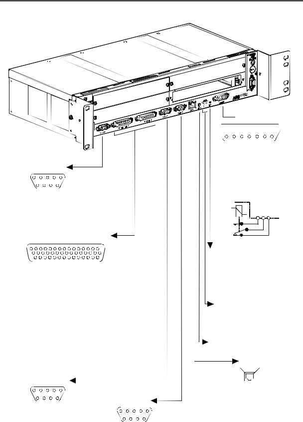
The ADR155C is placed in 19" racks or ETSI frames. It consists of:
Sa 2U subrack fitted with a motherboard grouping together the basic functions of the equipment, a backplane and a secured 48V DC power supply,
San ADRFAN module, consisting of two redundant ventilation units,
Sfour traffic cards:
S IC1.1 or IC1.2 STM1 optical card (ADR IC1.1 or ADR IC1.2 card) allowing a VC4 connection or 3 VC3 connections or 63 VC12 connections or a combination of VC3/VC12 connections
S 21 x 2 Mbit/s card, G.703, (ADR21E120 card), allowing 21 VC12 connections
S Ethernet 10/100 card (LAN1 ADR card), allowing 2 VC3 connections.
Installation and User Guide - N56717020101
No reproduction or communication without the written consent of SAGEM SA Page A1-1

1 - INSTALLATION AND COMMISSIONING
P
B
A
V
D
M
C
Left uprights |
|
of rack |
|
ADR 155C |
|
19" SUBRACK |
|
76,2mm |
|
2U |
|
6<1& |
( 287387 |
2 |
|
1 |
Two M6x12 |
HM screw |
Two M6 cage nuts
19" rack mounting
ADR 155C Subrack
76,2mm |
1 |
ADR 155C
ETSI RACK
2U |
|
6<1& |
( 287387 |
|
2 |
Two M6x12
HM screw
Two M6 cage nuts
ETSI rack mouting
Figure 1-1- ADR155C Subrack Installation
Installation and User Guide - N56717020101
Page A1-2 No reproduction or communication without the written consent of SAGEM SA
1 - INSTALLATION AND COMMISSIONING
1.2 - Subrack installation
The ADR 155C subrack can be installed in 19" rack or ETSI frame (see Figure 1-1). It consists of:
Sa motherboard located in the lower part (item M),
Sfour non-dedicated slots (items A to D), designed to accommodate the traffic cards,
Sa slide located on the left of the subrack designed to accommodate the ventilation module (item V),
Sa power supply (item P).
All connections are performed on front panel, either on the subrack, or on the modules.
Installation in a 19" rack
Elements attaching the subrack in 19" rack (brackets, cage nuts and attaching screws), are provided in its package.
The ADR155C has a system of thermal control by ventilation ; during the installation, provide for sufficient space for the ventilation aperture on the left of the subrack, and also for the aeration, at the top and right of the subrack. On the other hand, never hinder the natural air convection on the right side.
Perform the following operations:
Sprovide a 2U place in the rack for each equipment and a 1U space between equipments,
Ssecure the attaching brackets for mounting in 19" rack, on either side of the subrack,
Sclip, on either side of the rack, two M6 cage nuts (item 1),
Sposition the 19" subrack back in front of the rack,
Sslide the 19" subrack until attaching brackets are in contact with uprights, opposite the 4 cage nuts, and then secure the subrack with 4 M6x12 hex head screws (item 2).
Installation in an ETSI rack
The installation of the subrack in ETSI rack is identical with that in 19" rack.
In this case, use the set of attaching brackets specific for mounting in ETSI rack.
Installation of cards
RECALL: Prior to any operation on the cards, the operator must be provided with an antistatic bracelet.
ADR155C slots are non-dedicated. However, in order to make wiring easier and ensure the homogeneity among sites, it is advisable to proceed as follows:
Sposition the tributary cards from C clockwise
Sposition the agregate cards from D counter-clockwise
Scheck the ventilation module presence in its reserved slide,
Ssecure each card through M3 screws of Torx type (6-branch star), using a suited screwdriver.
Installation and User Guide - N56717020101
No reproduction or communication without the written consent of SAGEM SA Page A1-3

1 - INSTALLATION AND COMMISSIONING
1.3 - Connecting ports
The connections to be performed on the equipment depend on the configuration chosen: On the power supply card:
Sposer supply ports: "PWR" or "PWRA" and/or "PWRB", On the subrack motherboard strip:
Smanagement ports : "COMM", "ETH" and/or "MNGT"
SRemote indication, remote control and station alarm port : "LOOPS"
S2Mbit/s G.703 synchronization port : "SYNC"
S21x2Mbit/s G.703 traffic ports: "E1 INPUT" and "E1 OUTPUT". Depending on the traffic modules used
Soptical STM-1 ports and order wire channels ports,
SEthernet port
S21x2Mbit/s G.703 traffic ports.
Connection requirements :
ÖFor a right distribution of cords on either side of the subrack, the connections of slots A and C, the 21 2Mbit/s accesses and synchronization access are oriented leftward. All other connections are oriented leftward.
ÖThe run of cords must not hinder the extraction of a module; in particular, connecting cables of the left subrack half is to be secured to the frame with enough backlash to enable the ventilation module to be extracted during a maintenance operation.
1.3.1- Connecting Power Supply
S"PWRA" and/or "PWRB" ports, when the equipment is powered from one or two 48 V sources, the power source(s) should be limited to 100 VA.
S. "PWR" port when the equipment is powered from a mains voltage (230 V AC), via an optional 110-240//48V 60W/ transformer.
Observe the following connection requirements :
Ö"PWR" and "PWRA" and/or "PWRB" Power supply ports can be connected simultaneously.
ÖThe power cord or the 110-240//48V 60W/ transformer must not be connected to the primary source prior to being connected to the equipment.
ÖThe 110-240//48V 60W/ transformer must be mounted far from any heat source, and no traction must be exerted on its connecting wires.
Installation and User Guide - N56717020101
Page A1-4 No reproduction or communication without the written consent of SAGEM SA
1 - INSTALLATION AND COMMISSIONING
Description of power supply ports
POWER |
|
|
|
|
- 48V |
|
|
|
|
2A MAX |
|
|
|
|
"PWR" Jack type connector |
|
|||
F4AL250V Fuse |
4A Quick fuse |
|
||
|
low power shutdown |
|||
|
250V |
|
||
PWRA and PWRB |
|
|
|
|
|
1 |
- 48 B1 |
|
|
5 |
2 |
- 48 B1 |
6 OB1 |
|
9 |
||||
|
|
|
||
|
3 |
- Reserved |
7 OB1 |
|
6 |
4 |
- 48 B2 |
8 OB2 |
|
1 |
||||
|
5 |
- 48 B2 |
9 OB2 |
|
ADR-155C |
|
|
|
|
|
Figure 1-2 – Connecting power supply ports |
||||||||
"PWRA"/"PWRB" power supply interface: |
|||||||||
Input voltage : |
One or two Safety Extra Low Voltage (SELV) type – 48V sources |
||||||||
|
Voltage range allowed: - 36 V to - 60 V |
||||||||
|
Maximum voltage range : - 36 V to - 72 V |
||||||||
Power |
100 VA maximum |
|
|
|
|
||||
Connector |
Male 9-way HE5 |
|
|
|
|
||||
|
|
|
|
|
|
|
|
|
|
|
5 |
1 |
|
|
|||||
|
9 |
|
6 |
|
|
||||
|
|
|
|
|
|
|
|
||
|
|
|
|
|
|||||
|
Pin N° |
|
Signal name |
|
|||||
|
|
|
|
|
|
|
|
||
|
1 |
|
|
|
|
-48B1 |
|
||
|
|
6 |
|
|
|
OB1 |
|
||
|
2 |
|
|
|
|
-48B1 |
|
||
|
|
7 |
|
|
|
OB1 |
|
||
|
3 |
|
|
|
|
Reserved |
|
||
|
|
8 |
|
|
|
OB2 |
|
||
|
4 |
|
|
|
|
-48B2 |
|
||
|
|
9 |
|
|
|
OB2 |
|
||
|
5 |
|
|
|
|
-48B2 |
|
||
NOTA : The shielding of the connector is connected to the equipment ground |
|||||||||
"PWR" power supply interface: |
|
|
|
|
|||||
Port |
Connecting transformer 110-240//48V 60W/ |
||||||||
Connector |
Jack (core = OB1 and shield = - 48 V1). |
||||||||
Installation and User Guide - N56717020101
No reproduction or communication without the written consent of SAGEM SA Page A1-5
1 - INSTALLATION AND COMMISSIONING
"SYNC"
|
5 |
|
|
1 |
|
9 |
|
|
6 |
1 |
: GND |
|
|
|
2 |
: TX1_TIP |
6 |
: TX1_RING |
|
3 |
: RX1_TIP |
7 |
: RX2_TIP |
|
4 |
: RX2_RING |
8 |
: RX1_RING |
|
5 |
: RESERVED |
9 |
: RESERVED |
|
"E1 OUTPUT"and "E1 INPUT"
15 |
|
|
|
1 |
|
30 |
|
|
|
16 |
|
|
44 |
|
|
|
31 |
|
|
16 |
: GND |
|
|
1 |
: Tx(Rx) 1A |
17 |
: Tx(Rx) 2B |
31 |
: Tx(Rx) 1B |
2 |
: Tx(Rx) 3B |
18 |
: Tx(Rx) 3A |
32 |
: Tx(Rx) 2A |
3 |
: Tx(Rx) 4A |
19 |
: Tx(Rx) 5B |
33 |
: Tx(Rx) 4B |
4 |
: Tx(Rx) 6B |
20 |
: Tx(Rx) 6A |
34 |
: Tx(Rx) 5A |
5 |
: Tx(Rx) 7A |
21 |
: Tx(Rx) 8B |
35 |
: Tx(Rx) 7B |
6 |
: Tx(Rx) 9B |
22 |
: Tx(Rx) 9A |
36 |
: Tx(Rx) 8A |
7 |
: Tx(Rx) 10A |
23 |
: Tx(Rx) 11B |
37 |
: Tx(Rx) 10B |
8 |
: Tx(Rx) 12B |
24 |
: Tx(Rx) 12A |
38 |
: Tx(Rx) 11A |
9 |
: Tx(Rx) 13A |
25 |
: Tx(Rx) 14B |
39 |
: Tx(Rx) 13B |
10 |
: Tx(Rx) 15B |
26 |
: Tx(Rx) 15A |
40 |
: Tx(Rx) 14A |
11 |
: Tx(Rx) 16A |
27 |
: Tx(Rx) 17B |
41 |
: Tx(Rx) 16B |
12 |
: Tx(Rx) 18B |
28 |
: Tx(Rx) 18B |
42 |
: Tx(Rx) 17A |
13 |
: Tx(Rx) 19A |
29 |
: Tx(Rx) 20B |
43 |
: Tx(Rx) 19B |
14 |
: Tx(Rx) 21B |
30 |
: Tx(Rx) 21A |
44 |
: Tx(Rx) 20A |
15 |
: GND |
|
|
|
|
"MNGT"
|
5 |
|
|
1 |
|
|
|
|
|
|
|
||
|
9 |
|
|
|
6 |
|
|
COMM |
|||||
1 |
: GND |
|
|
|
|
|
|||||||
|
|
|
|
|
|
|
|
|
|
||||
|
|
|
5 |
|
|
|
1 |
||||||
2 |
: RXPA |
6 |
: RXPB |
|
|
|
|||||||
9 |
|
|
|
|
6 |
||||||||
3 |
: TXPA |
7 |
: TXPB |
|
|
|
|||||||
1 : DCD |
|
|
|
|
|||||||||
4 |
: TXCLKPA |
8 |
: TXCLKPB |
6 |
: DSR |
||||||||
5 |
: RXCLKPA |
9 |
: RXCLKPB |
2 : RX |
|||||||||
3 : |
TX |
7 |
: RTS |
||||||||||
|
|
|
|
|
|
||||||||
|
|
|
|
|
|
4 : |
DTR |
8 |
: CTS |
||||
|
|
|
|
|
|
5 : |
Gnd |
9 |
: NC * |
||||
 LOOPS
LOOPS
8 


 1
1
15 |
|
|
|
9 |
|
1 |
: Break B |
|
|
|
|
2 |
: Make B |
9 : Common B |
|||
3 |
: Common A |
10 |
: Break A |
||
4 |
: Gnd |
11 |
: Make A |
||
5 |
: R-MON 4 N 12 |
: R-MON 4 P (OB) |
|||
6 |
: R-MON 3 N 13 |
: R-MON 3 P (OB) |
|||
7 |
: R-MON 2 N 14 |
: R-MON 2 P (OB) |
|||
8 |
: R-MON 1 N 15 |
: R-MON 1 P (OB) |
|||
Schematic diagram of a dry loop
M C B
Green "ON" LED |
|
On |
In service card |
Flashing |
Autotest default |
Off |
No powered equipment |
|
or not run software |
|
"ALA" LEDs |
|
|
|
Red "M" LED |
|
|
|
ON |
|
: major alarm |
|
Yellow "m" LED |
|
|
|
OFF |
|
: minor alarm |
|
"ACK" Push button |
||
|
alarm acquittement |
||
|
|
ETH |
|
|
Pin 1 |
|
Pin 8 |
1 |
: TX_ETH_TIP |
5 : NC |
|
2 |
: TX_ETH_RING 6 : RX_ETH_RING |
||
3 |
: RX_ETH_TIP |
7 : NC |
|
4 |
: NC * |
|
8 : NC |
|
Yellow LED |
: link status |
|
|
ON |
: correct link |
|
|
Green LED |
: traffic status |
|
|
ON |
: on reception |
|
NC * : Reserved
|
Figure 1-3 – Connecting mother board inputs |
|
|
Installation and User Guide - N56717020101 |
|
Page A1-6 |
No reproduction or communication without the written consent of SAGEM SA |

1 - INSTALLATION AND COMMISSIONING
1.3.2- Connecting on motherboard
1.3.2.1- Remote indication, remote control and station alarm port ("LOOPS")
"LOOPS" Interface: |
|
|
|
|
|
|
||||||||
Ports |
|
|
4 remote indication inputs for floating contacts (Local user inputs), biased to |
|||||||||||
|
|
|
|
-48 V internally, active when closed and with electrical isolation |
||||||||||
|
|
|
|
(loop current = from 1 to 10 mA), |
||||||||||
|
|
|
|
2 dry loop outputs (common, normally closed and normally open) (Local user |
||||||||||
|
|
|
|
outputs) for station alarm or remote control use (maximum current = 100 mA |
||||||||||
|
|
|
|
on resistive load), |
|
|
|
|
|
|
||||
Connector |
Female 15-way HE5 |
|
|
|
|
|
|
|||||||
|
|
|
|
|
|
|
|
|
|
|
|
|
|
|
|
|
|
|
8 |
|
|
1 |
|
||||||
|
|
|
|
15 |
|
|
9 |
|
||||||
|
|
|
|
|
|
|
|
|
|
|
|
|
|
|
|
|
|
|
|
|
|
|
|
|
|
|
|
||
|
|
Pin N° |
|
Signal name |
|
|
|
|
|
Comments |
||||
|
|
|
|
|
|
|
|
|
|
|||||
1 |
|
|
|
BREAK B |
Normally closed contact of dry loop B |
|||||||||
|
|
|
|
|
|
|
|
|
|
|||||
|
|
|
9 |
|
COMMON B |
Common contact of dry loop B |
||||||||
2 |
|
|
|
MAKE B |
Normally open contact of dry loop B |
|||||||||
|
|
|
10 |
|
Break A |
Normally closed contact of dry loop A |
||||||||
3 |
|
|
|
COMMON A |
Common contact of dry loop A |
|||||||||
|
|
|
|
|
|
|
|
|
|
|||||
|
|
|
11 |
|
Make A |
Normally open contact of dry loop A |
||||||||
|
|
|
|
|
|
|
|
|
|
|
|
|
||
4 |
|
|
|
GND |
Ground |
|
|
|
|
|||||
|
|
|
|
|
|
|
|
|
|
|||||
|
|
|
12 |
|
R- MON 4 P (OB) |
User imput N°4 |
||||||||
|
|
|
|
|
|
|
|
|
|
|
|
|
||
5 |
|
|
|
R-MON 4 N |
|
|
|
|
|
|
||||
|
|
|
|
|
|
|
|
|
|
|||||
|
|
|
13 |
|
R- MON 3 P (OB) |
User imput N°3 |
||||||||
|
|
|
|
|
|
|
|
|
|
|
|
|
||
6 |
|
|
|
R- MON 3 N |
|
|
|
|
|
|
||||
|
|
|
14 |
|
R- MON 2 P (OB) |
User imput N°2 |
||||||||
7 |
|
|
|
R- MON 2 N |
|
|
|
|
|
|
||||
|
|
|
15 |
|
R- MON 1 P (OB) |
User imput N°1 |
||||||||
8 |
|
|
|
R- MON 1 N |
|
|
|
|
|
|
||||
NOTE: |
|
OB is the result of a logical "OR" between signals OB1 and OB2 on the "PWR", "PWRA" and "PWRB" |
||||||||||||
|
|
|
power supply interfaces. |
|
|
|
|
|
|
|||||
"ETH" Interface: |
|
|
|
|
|
|
|
|
|
|
|
|||
Port |
|
|
Ethernet management interface operating at 10 Mbit/s in half-duplex or full- |
|||||||||||
|
|
|
|
duplex mode according to the mode used by the interlocutor (dynamic |
||||||||||
|
|
|
|
adaptation of the Ethernet port on each new log-in of the interlocutor), |
||||||||||
Connector |
RJ48 Type (RJ45 shielded). |
|
|
|
|
|||||||||
|
|
|
|
|
Pin 1 |
|
Pin 8 |
|
|
|
|
|||
|
|
|
|
|
|
|
|
|
|
|
Front view |
|||
|
|
|
|
|
|
|
|
|
|
|
||||
|
|
|
|
|
|
|
|
|
|
|
||||
|
|
|
|
|
|
|
|
|
|
|||||
|
|
|
Pin N° |
|
Signal name |
|
|
|
Comments |
|||||
|
|
|
|
|
|
|
||||||||
|
|
1 |
|
TX_ETH_TIP |
|
Output (hot point) |
||||||||
|
|
|
|
|
|
|
||||||||
|
|
2 |
|
TX_ETH_RING |
|
Output (cold point) |
||||||||
|
|
|
|
|
|
|
||||||||
|
|
3 |
|
RX_ETH_TIP |
|
Input (hot point) |
||||||||
|
|
|
|
|
|
|
|
|
||||||
|
|
4 |
|
NC |
|
|
|
Reserved |
||||||
|
|
|
|
|
|
|
|
|
||||||
|
|
5 |
|
NC |
|
|
|
Reserved |
||||||
|
|
6 |
|
RX_ETH_RING |
|
Input (cold point) |
||||||||
|
|
|
7 and 8 |
|
NC |
|
|
|
Reserved |
|||||
Installation and User Guide - N56717020101
No reproduction or communication without the written consent of SAGEM SA Page A1-7
1 - INSTALLATION AND COMMISSIONING
NOTE: Two LEDs are linked to the "ETH" port:
|
• LED, "Activity", green colour |
|
|
|
|
|
|
: Trafic status indicator, |
|||||||||||||||||||
|
• LED, "Link", yellow colour |
|
|
|
|
|
|
: Link status indicator. |
|||||||||||||||||||
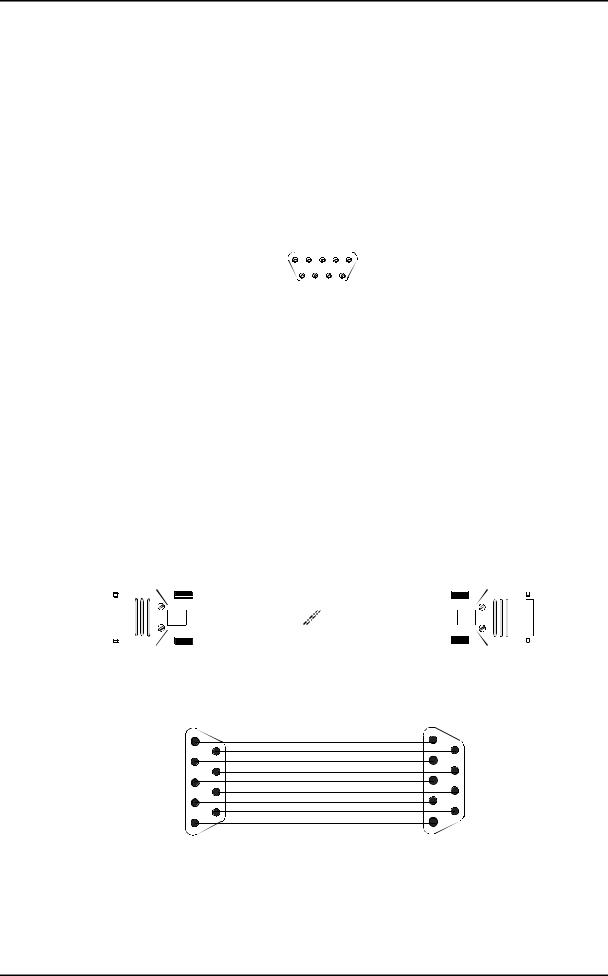
1.3.2.2 - Management and Administration ports |
|||||||||||||||||||||||||||
|
"COMM" Interface: |
|
|
|
|
|
|
|
|
|
|
|
|
|
|
|
|
|
|||||||||
|
Ports |
RS232, connecting VT100 standard console or emulation |
|||||||||||||||||||||||||
|
Bit rate |
19200 bauds (8 data bits, no parity bit and 1 stop bit), |
|||||||||||||||||||||||||
|
Connector |
Female 9-way HE5 |
|
|
|
|
|
|
|
|
|
|
|
|
|
|
|
|
|
||||||||
|
|
|
|
|
|
|
|
|
|
|
|
|
|
|
|
|
|
|
|
|
|
|
|
|
|
|
|
|
|
|
|
|
|
|
|
|
|
|
5 |
|
|
1 |
|
|
|
|
|
|
|
|
|
||||
|
|
|
|
|
|
|
|
|
|
|
9 |
|
|
|
6 |
|
|
|
|
|
|
|
|
|
|||
|
|
|
|
|
|
|
|
|
|
|
|
|
|
|
|
|
|
|
|
|
|
|
|
|
|
|
|
|
|
|
|
|
|
|
|
|
|
|
|
|
|
|
|
|
|
|
|
|
|
|
|
|
|
|
|
|
Pin N° |
|
|
|
|
|
Signal name |
|
|
|
|
|
|
|
|
Comments |
|||||||||||
|
|
|
|
|
|
|
|
|
|
|
|
|
|
|
|
|
|
|
|
|
|
|
|||||
|
1 |
|
|
|
|
|
|
|
|
DCD |
Connected to DSR |
||||||||||||||||
|
|
6 |
|
|
|
|
|
|
DSR |
Data Set Ready (to DCE)* |
|||||||||||||||||
|
2 |
|
|
|
|
|
|
|
|
RX |
Received data (to DCE)* |
||||||||||||||||
|
|
7 |
|
|
|
|
|
|
RTS |
Request To Send (from DCE)* |
|||||||||||||||||
|
3 |
|
|
|
|
|
|
|
|
TX |
Transmitted data (from DCE)* |
||||||||||||||||
|
|
8 |
|
|
|
|
|
|
CTS |
Clear To Send (to DCE)* |
|||||||||||||||||
|
4 |
|
|
|
|
|
|
|
|
DTR |
Data Terminal Ready (from DCE)* |
||||||||||||||||
|
|
9 |
|
|
|
|
|
|
RI |
Ring Indicator (not connected) |
|||||||||||||||||
|
|
|
|
|
|
|
|
|
|
|
|
|
|
|
|
|
|
|
|
|
|
|
|
|
|
||
|
5 |
|
|
|
|
|
|
|
|
GND |
Ground |
|
|
|
|
|
|
|
|
|
|
|
|
||||
|
|
|
|
|
|
|
|
|
|
|
|
|
|
|
|
|
|
|
|
|
|
|
|
|
|
|
|
|
* The ADR155C is seen as DCE |
|
|
|
|
|
|
|
|
|
|
|
|
|
|
|
|
|
|||||||||
|
Connection cable |
See below. |
|
|
|
|
|
|
|
|
|
|
|
|
|
|
|
|
|
||||||||
|
Equipment side |
|
|
|
|
|
|
|
|
VT100 or PC |
|||||||||||||||||
|
|
"COMM" |
|
|
|
|
|
|
|
|
|
side |
|||||||||||||||
|
|
|
|
|
|
|
|
|
|
|
|
|
|
|
|
|
|
|
|
|
|
|
|
|
|
|
|
|
|
|
|
|
|
|
|
|
|
|
|
|
|
|
|
|
|
|
|
|
|
|
|
|
|
|
|
|
|
|
|
|
|
|
|
|
|
|
|
|
|
|
|
|
|
|
|
|
|
|
|
|
|
|
|
|
|
|
|
|
|
|
|
|
|
|
|
|
|
|
|
|
|
|
|
|
|
|
|
|
|
|
|
|
|
|
|
|
|
|
|
|
|
|
|
|
|
|
|
|
|
|
|
|
|
|
|
|
|
|
|
|
|
|
|
|
|
|
|
|
|
|
|
|
|
|
|
|
|
|
|
|
|
|
|
|
|
|
|
|
|
|
|
|
|
|
|
|
|
|
|
|
|
|
|
|
|
|
|
|
|
|
|
|
|
|
|
|
|
|
|
|
|
|
|
|
|
|
|
|
|
|
|
|
|
|
|
|
|
|
|
|
|
|
|
Male 9-way connector Female 9-way connector
|
|
Wiring diagram |
|
1 |
6 |
1 |
|
|
6 |
||
5 |
9 |
9 |
|
5 |
|||
|
|
Installation and User Guide - N56717020101
Page A1-8 No reproduction or communication without the written consent of SAGEM SA
1 - INSTALLATION AND COMMISSIONING
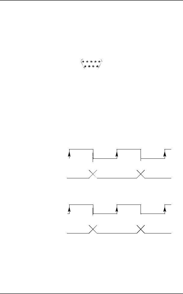
"MNGT" Interface: |
|
|
|
|
|
|
||
Port |
V.11 synchronous (differential) interconnection possible with other SAGEM |
|||||||
|
|
equipment ADR155C, FOT 155C, through serial synchronous links used in |
||||||
|
|
codirectional mode at 64 kbit/s or master contra-directional mode (rate |
||||||
|
|
defined by the ADR 155C) |
|
|
|
|||
Bit rate |
64 kbit/s, |
|
|
|
|
|
|
|
Connector |
Female 9-way HE5. |
|
|
|
|
|
||
|
|
|
|
|
|
|
|
|
|
|
|
|
5 |
1 |
|
||
|
|
|
|
9 |
|
6 |
|
|
|
|
|
|
|
|
|
|
|
|
|
|
|
|
|
|
|
|
Pin N° |
Signal name |
Polarity |
|
|
|
|
Comments |
|
|
|
|
|
|
||||
1 |
|
GND |
|
Ground (no connected) |
||||
|
|
|
|
|
||||
|
6 |
RXPB |
(+) |
Input for data received over the P interface and sampled on the |
||||
|
|
|
|
rising edge of receive clock RXCLKP (B-A) |
||||
2 |
|
RXPA |
(-) |
|||||
|
|
|
|
|
|
|||
|
|
|
|
|
||||
|
7 |
TXPB |
(+) |
Output for data sent over the P interface on the falling edge of |
||||
|
|
|
|
transmit clock TXCLKP (B-A) |
||||
3 |
|
TXPA |
(-) |
|||||
|
|
|
|
|
|
|||
|
8 |
TXCLKPB |
(+) |
Output for transmit clock; in codirectional mode, the transmit clock |
||||
|
|
|
|
timing is derived from the equipment's internal timing |
||||
4 |
|
TXCLKPA |
(-) |
|||||
|
|
|
|
|
|
|||
|
9 |
RXCLKPB |
(+) |
Receive clock input |
||||
5 |
|
RXCLKPA |
(-) |
|
|
|
|
|
*In slave contradirectional mode (coming) TXCLK signals are inputs.
Timing diagram for the "MNGT" interface in codirectional mode (64 kbit/s synchronous use):
TXCLKP (B-A)
(codirectional transmit clock output)
TXP (B-A) |
|
|
|
|
|
|
|
|
|
|
|
|
|
|
|
|
|
|
|
|
|
|
|
|
|
|
|
|
|
|
|
|
|
|
|
|
|
|
|
|
|
|
|
|
|
|
|
|
|
|
|
|
|
|
|
|
|
|
|
|
|
|
B8 |
|
|
B1 |
|
|
B2 |
||
(output for data transmitted |
|
|
|
|
||||
|
||||||||
|
|
|
|
|||||
|
|
|
|
|
|
|
|
|
over P interface)
RXCLKP (B-A)
(receive clock input)
RXP (B-A) |
|
|
|
|
|
|
|
|
|
|
|
|
|
|
|
|
|
|
|
|
|
|
|
|
|
|
|
|
|
|
|
|
|
|
|
|
|
|
|
|
|
|
|
|
|
|
|
|
|
|
|
|
|
|
|
|
|
|
|
|
|
|
|
|
|
|
|
|
|
|
|
B8 |
|
B1 |
|
|
B2 |
||
|
|
|
|||||
|
|
|
|||||
(input for data received |
|
|
|
||||
|
|
|
|
|
|
|
|
over the P interface)
Installation and User Guide - N56717020101
No reproduction or communication without the written consent of SAGEM SA Page A1-9

1 - INSTALLATION AND COMMISSIONING
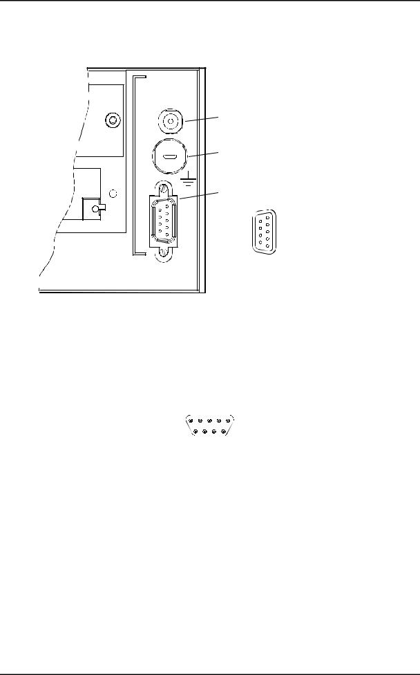
1.3.2.3 - G.703 2 Mbit/s Synchronization port
"SYNC" Interface |
|
|
|
|
|
|
||
Ports |
Two G.703 2MHz external synchronization inputs (T3) and one G.703 2MHz |
|||||||
|
|
|
clock output (T4) compliant with ITU-T G.703 Recommendation |
|||||
|
|
|
(§ 10.3 for input port, § tab.10 for output port) |
|||||
Bit rate |
2,048 Mbit/s ± 50 ppm, |
|
||||||
Impedance |
120 Ω balanced, |
|
||||||
Connector |
Female 9-way HE5 (120 Ω). |
|
||||||
|
|
|
5 |
|
|
|
1 |
|
|
|
|
|
|
|
|||
|
|
|
9 |
|
|
|
6 |
|
|
|
|
|
|
|
|||
|
Pin N° |
|
Signal name |
Comments |
||||
|
|
|
|
|
|
|||
|
1 |
|
|
GND |
Ground |
|||
|
|
6 |
|
TX1 RING (T4-) |
Output T4-1 (cold point) |
|||
|
2 |
|
|
TX1 TIP (T4+) |
Output T4-1 (hot point) |
|||
|
|
|
|
|
|
|||
|
|
7 |
|
RX2 TIP (T3+) |
Input T3-2 (hot point) |
|||
|
|
|
|
|
|
|||
|
3 |
|
|
RX1 TIP (T3+) |
Input T3-1 (hot point) |
|||
|
|
|
|
|
|
|||
|
|
8 |
|
RX1 RING (T3-) |
Input T3-1 (cold point) |
|||
|
|
|
|
|
|
|||
|
4 |
|
|
RX2 RING (T3-) |
Input T3-2 (cold point) |
|||
|
|
|
|
|
|
|||
|
|
9 |
|
NC |
Reserved |
|||
|
|
|
|
|
|
|||
|
5 |
|
|
NC |
Reserved |
|||
NOTA : The shielding of the connector case is connected to the subrack front panel ground
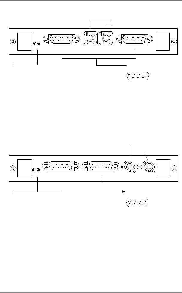
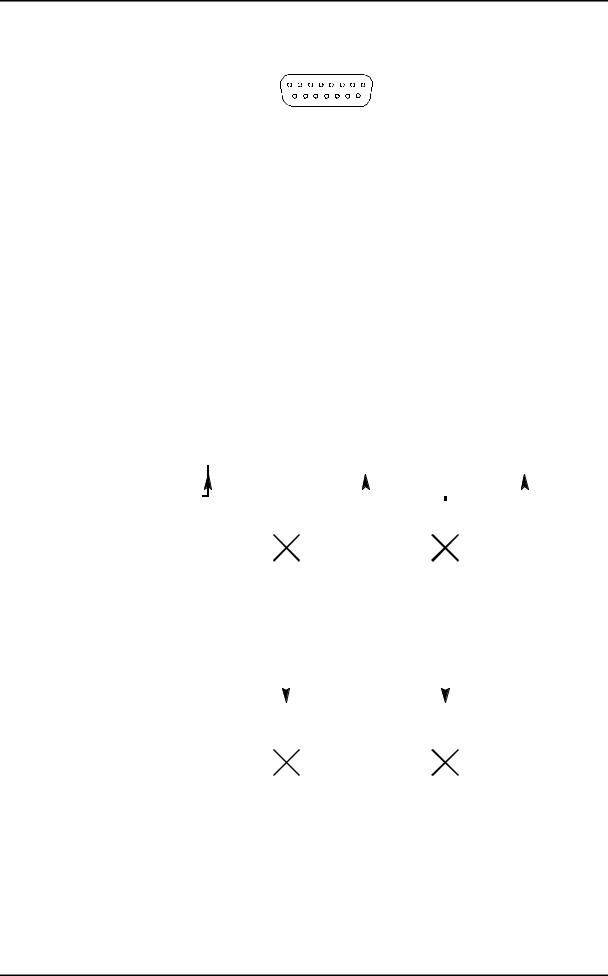
1.3.2.4 - G.703, 21 x 2 Mbit/s traffic port
"E1 INPUT" and "E1 OUTPUT" Interface |
|
|
ports |
21 x 2 Mbit/s traffic ports compliant with the ITU-T G.703 Recommendation |
|
|
(§ 6.3 for input port, § tab.6 for output port) |
|
Bit rate |
2,048 Mbit/s ± 50 ppm, |
|
Code |
HDB3, |
|
Impedance |
120 Ω balanced, |
|
Connector |
SUB D HD female 44 pins supporting L907 cable (21 ports). |
|
This interface |
uses two connectors : E1 INPUT |
connector for inputs (named RX) and |
E1 OUTPUT connector for outputs (named TX) |
|
|
|
15 |
1 |
|
30 |
16 |
|
44 |
31 |
Installation and User Guide - N56717020101
Page A1-10 No reproduction or communication without the written consent of SAGEM SA

1 - INSTALLATION AND COMMISSIONING
Pin N° |
Ports |
Signal name |
Comments |
||
|
|
|
|
|
|
|
16 |
|
|
GND |
ground |
|
|
|
|
|
|
|
|
31 |
1 |
TX(RX) 1B |
Output (Input) 2 Mbit/s (hot point) |
|
|
|
|
|
|
1 |
|
|
|
TX(RX) 1A |
Output (input) 2 Mbit/s (cold point) |
|
|
|
|
|
|
|
17 |
|
2 |
TX(RX) 2B |
Output (Input) 2 Mbit/s (hot point) |
|
|
|
|
|
|
|
|
32 |
|
TX(RX) 2A |
Output (input) 2 Mbit/s (cold point) |
|
|
|
|
|
|
2 |
|
|
3 |
TX(RX) 3B |
Output (Input) 2 Mbit/s (hot point) |
|
|
|
|
|
|
|
18 |
|
|
TX(RX3A |
Output (input) 2 Mbit/s (cold point) |
|
|
33 |
4 |
TX(RX) 4B |
Output (Input) 2 Mbit/s (hot point) |
3 |
|
|
|
TX(RX) 4A |
Output (input) 2 Mbit/s (cold point) |
|
19 |
|
5 |
TX(RX) 5B |
Output (Input) 2 Mbit/s (hot point) |
|
|
34 |
|
TX(RX) 5A |
Output (input) 2 Mbit/s (cold point) |
4 |
|
|
6 |
TX(RX) 6B |
Output (Input) 2 Mbit/s (hot point) |
|
20 |
|
|
TX(RX) 6A |
Output (input) 2 Mbit/s (cold point) |
|
|
35 |
7 |
TX(RX) 7B |
Output (Input) 2 Mbit/s (hot point) |
5 |
|
|
|
TX(RX) 7A |
Output (input) 2 Mbit/s (cold point) |
|
21 |
|
8 |
TX(RX) 8B |
Output (Input) 2 Mbit/s (hot point) |
|
|
36 |
|
TX(RX) 8A |
Output (input) 2 Mbit/s (cold point) |
6 |
|
|
9 |
TX(RX) 9B |
Output (Input) 2 Mbit/s (hot point) |
|
22 |
|
|
TX(RX) 9A |
Output (input) 2 Mbit/s (cold point) |
|
|
37 |
10 |
TX(RX) 10B |
Output (Input) 2 Mbit/s (hot point) |
7 |
|
|
|
TX(RX) 10A |
Output (input) 2 Mbit/s (cold point) |
|
23 |
|
11 |
TX(RX) 11B |
Output (Input) 2 Mbit/s (hot point) |
|
|
38 |
|
TX(RX) 11A |
Output (input) 2 Mbit/s (cold point) |
8 |
|
|
12 |
TX(RX) 12B |
Output (Input) 2 Mbit/s (hot point) |
|
24 |
|
|
TX(RX) 12A |
Output (input) 2 Mbit/s (cold point) |
|
|
39 |
13 |
TX(RX) 13B |
Output (Input) 2 Mbit/s (hot point) |
|
|
|
|
|
|
9 |
|
|
|
TX(RX) 13A |
Output (input) 2 Mbit/s (cold point) |
|
|
|
|
|
|
|
25 |
|
14 |
TX(RX) 14B |
Output (Input) 2 Mbit/s (hot point) |
|
|
|
|
|
|
|
|
40 |
|
TX(RX) 14A |
Output (input) 2 Mbit/s (cold point) |
|
|
|
|
|
|
10 |
|
|
15 |
TX(RX) 15B |
Output (Input) 2 Mbit/s (hot point) |
|
|
|
|
|
|
|
26 |
|
|
TX(RX) 15A |
Output (input) 2 Mbit/s (cold point) |
|
|
|
|
|
|
|
|
41 |
16 |
TX(RX) 16B |
Output (Input) 2 Mbit/s (hot point) |
11 |
|
|
|
TX(RX) 16A |
Output (input) 2 Mbit/s (cold point) |
|
27 |
|
17 |
TX(RX) 17B |
Output (Input) 2 Mbit/s (hot point) |
|
|
42 |
|
TX(RX) 17A |
Output (input) 2 Mbit/s (cold point) |
12 |
|
|
18 |
TX(RX) 18B |
Output (Input) 2 Mbit/s (hot point) |
|
28 |
|
|
TX(RX) 18A |
Output (input) 2 Mbit/s (cold point) |
|
|
43 |
19 |
TX(RX) 19B |
Output (Input) 2 Mbit/s (hot point) |
13 |
|
|
|
TX(RX) 19A |
Output (input) 2 Mbit/s (cold point) |
|
29 |
|
20 |
TX(RX) 20B |
Output (Input) 2 Mbit/s (hot point) |
|
|
44 |
|
TX(RX) 20A |
Output (input) 2 Mbit/s (cold point) |
14 |
|
|
21 |
TX(RX) 21B |
Output (Input) 2 Mbit/s (hot point) |
|
30 |
|
|
TX(RX) 21A |
Output (input) 2 Mbit/s (cold point) |
15 |
|
|
|
GND |
Ground |
NOTA : The shielding of the connector case is connected to the subrack front panel ground
Installation and User Guide - N56717020101
No reproduction or communication without the written consent of SAGEM SA Page A1-11
1 - INSTALLATION AND COMMISSIONING
STM1 transmission port
STM1 reception port
ADR IC1
STATUS |
EOW |
TR |
REC |
AUX |
 "EOW and "AUX"
LED |
|
STATUS |
Green |
Red |
|
ON |
OFF |
Card in service |
ON |
ON |
Card in alarm |
OFF |
OFF |
Hardware default (fuse) |
OFF |
ON |
Card out of service |
Flashing |
|
Autotest default |
|
8 |
|
1 |
15 |
|
9 |
|
1 |
: NC |
|
|
2 |
: TA |
9 : TB |
|
3 |
: TOF PA |
10 |
: TOF PB |
4 |
: RA |
11 |
: RB |
5 |
: ROF PA |
12 |
: ROF PB |
6 |
: R64 A |
13 |
: R64 B |
7 |
: T64 A |
14 |
: T64 B |
8 |
: GND |
15 |
: NC |
Version 1
STM1 transmission port
STM1 reception port
ADR IC1.1
STATUS |
EOW |
AUX |
TR REC
LED |
|
STATUS |
Green |
Red |
|
ON |
OFF |
Card in service |
ON |
ON |
Card in alarm |
OFF |
OFF |
Hardware default (fuse) |
OFF |
ON |
Card out of service |
Flashing |
|
Autotest default |
Version 2
"EOW and "AUX"
|
8 |
|
1 |
15 |
|
9 |
|
1 |
: NC |
|
|
2 |
: TA |
9 : TB |
|
3 |
: TOF PA |
10 |
: TOF PB |
4 |
: RA |
11 |
: RB |
5 |
: ROF PA |
12 |
: ROF PB |
6 |
: R64 A |
13 |
: R64 B |
7 |
: T64 A |
14 |
: T64 B |
8 |
: GND |
15 |
: NC |
NC: Reserved
Figure 1-4 - Connecting ADR IC1.x card inputs
Installation and User Guide - N56717020101
Page A1-12 No reproduction or communication without the written consent of SAGEM SA
1 - INSTALLATION AND COMMISSIONING
1.3.3 - Connecting on the ADR IC1.x card
Each ADR IC1.x module provides connection for:
San STM1 interface ("TR" transmission port and "REC" reception port)
Stwo order wire channels at 64 kbit/s (named "EOW" and "AUX"), which, by default, are conveyed in E1 and F1 bytes of the SOH, respectively.
1.3.3.1 - Connecting STM1 interface
Remove the contact protection connector,
Connect STM-1 interface to front panel FC/PC connectors:
Ö Transmission |
TR Connector |
Ö Reception |
REC Connector |
"TR" and "REC" ports: |
|
Interface Type |
IC 1.1 = L 1.1 + S 1.1 or IC 1.2 = L 1.2 + S 1.2, |
Bit rate |
155.520 Mbit/s ± 15 ppm, |
Standart |
ITU-T G.957/G.958, |
Encoding |
Not encoded (NRZ), |
Optical fiber* |
Single mode (1300 nm (IC1.1) or |
|
1550 nm (IC1.2), ITU-T G.652), |
Transmit optical power |
-5 to 0 dBm |
Max. receive power |
0 dBm |
Sensibility at 10-10 |
- 34 dB |
garanteed Attenuation |
0 - 28 dB with no external attenuator, |
Typical range |
0 - 60 km (IC1.1) or 0 - 90 km (IC1.2), |
Connector |
all ceramic FC/PC |
*: It is possible to use a multi-mode optical fiber with diameter smaller than or equal to 62.5 microns. The optical budget is then reduced to 25 % of the optical budget obtained with a mono-mode optical fiber. The transmission optical fiber is mono-mode type and the reception optical fiber is multi-mode type.
1.3.3.2 - Connecting order-wire channels
"EOW" and "AUX" Interface:
Port |
synchronous V.11 (differential), |
Bit rate |
64 kbit/s, |
Installation and User Guide - N56717020101
No reproduction or communication without the written consent of SAGEM SA Page A1-13
1 - INSTALLATION AND COMMISSIONING
Connector |
Female 15-way HE5. |
|
||
|
|
|
8 |
1 |
|
|
|
15 |
9 |
|
|
|
|
|
Pin N° |
Signal name |
Polarity |
Comments |
|
|
|
|
|
|
1 |
|
- |
|
Not connected |
|
|
|
|
|
|
9 |
TB |
(+) |
Input for data to send over the STM-1 line and sampled on the |
|
|
|
|
rising edge of clock T64 (B-A) |
2 |
|
TA |
(-) |
|
|
|
|||
|
|
|
|
|
|
10 |
TOFPB |
(+) |
Transmit mode byte sync output indicating the positioning of bit 1 |
|
|
|
|
and sent on the rising edge of clock T64 (B-A) |
3 |
|
TOFPA |
(-) |
|
|
|
|||
|
11 |
RB |
(+) |
Output for data extracted from STM-1 line and sampled on the |
4 |
|
RA |
(-) |
falling edge of clock T64 (B-A) |
|
|
|||
|
12 |
ROFPB |
(+) |
Receive mode byte sync output indicating the setting of bit 1 and |
5 |
|
ROFPA |
(-) |
sent on the falling edge of clock T64 (B-A) |
|
|
|||
|
13 |
R64B |
(+) |
64 kHz receive clock output |
6 |
|
R64A |
(-) |
|
|
14 |
T64B |
(+) |
64 kHz transmit clock output |
7 |
|
T64A |
(-) |
|
|
15 |
- |
|
Not connected |
8 |
|
|
|
Ground |
Timing diagram for the "EOW/AUX" interface in contra-directional mode (64 kbit/s synchronous use):
T64 (B-A)
(transmit clock output)
T (B-A)
(input for data to transmit over STM1 line)
TOFP (B-A)
(transmit synchro byte pulse output)
R64 (B-A)
(receive clock output)
R (B-A)
(output for data received from STM1 line)
ROFP (B-A)
(receive synchro byte pulse output)
|
|
|
|
|
|
|
|
|
|
|
|
|
|
|
|
|
|
|
|
|
|
|
|
|
|
|
|
|
|
|
|
|
|
|
|
|
|
|
|
|
|
|
|
|
|
|
|
|
|
|
|
|
|
|
|
|
|
|
|
|
|
|
|
|
|
|
|
|
|
|
|
|
|
|
|
|
|
|
|
|
|
|
|
|
|
|
|
|
|
|
|
|
|
|
|
|
|
|
|
|
|
|
|
|
|
|
|
|
|
|
|
|
|
|
|
|
|
|
|
|
|
|
|
|
|
|
|
|
|
|
|
|
|
|
|
|
|
|
|
|
|
|
|
|
B8 |
|
B1 |
|
B2 |
||||
|
|
|
||||||||
|
|
|
|
|
|
|
|
|
|
|
|
|
|
|
|
|
|
|
|
|
|
|
|
|
|
|
|
|
|
|
|
|
|
|
|
|
|
|
|
|
|
|
|
|
|
|
|
|
|
|
|
|
|
|
|
|
|
|
|
|
|
|
|
|
|
|
|
|
|
|
|
|
|
|
|
|
|
|
|
|
|
|
|
|
|
|
|
|
|
|
|
|
|
|
|
|
|
|
|
|
|
|
|
|
|
|
|
|
|
|
|
|
|
|
|
|
|
|
|
|
|
|
|
|
|
|
|
|
|
|
|
|
|
|
|
|
|
|
|
|
|
|
|
|
|
|
|
|
|
|
|
|
|
|
|
|
|
|
|
|
|
|
|
|
|
|
|
|
|
|
|
|
|
|
|
|
|
|
|
|
|
|
|
|
|
|
|
|
|
|
|
|
|
|
|
|
|
|
|
|
|
|
|
|
|
|
|
|
|
|
|
|
|
|
|
|
|
|
|
|
|
|
|
|
|
|
|
|
|
|
|
|
|
|
|
|
|
|
|
|
|
|
|
|
|
|
|
|
|
|
|
|
|
|
|
|
|
|
|
|
|
|
|
B8 |
|
|
B1 |
|
|
B2 |
|
|
|
|
|||
|
|
|
|
|||
|
|
|
|
|
|
|
|
|
|
|
|
|
|
|
|
|
|
|
|
|
|
|
|
|
|
|
|
|
|
|
|
|
|
|
|
|
|
|
|
|
|
|
|
|
|
|
|
|
|
|
|
|
|
|
|
|
|
|
|
|
|
|
Installation and User Guide - N56717020101
Page A1-14 No reproduction or communication without the written consent of SAGEM SA
1 - INSTALLATION AND COMMISSIONING
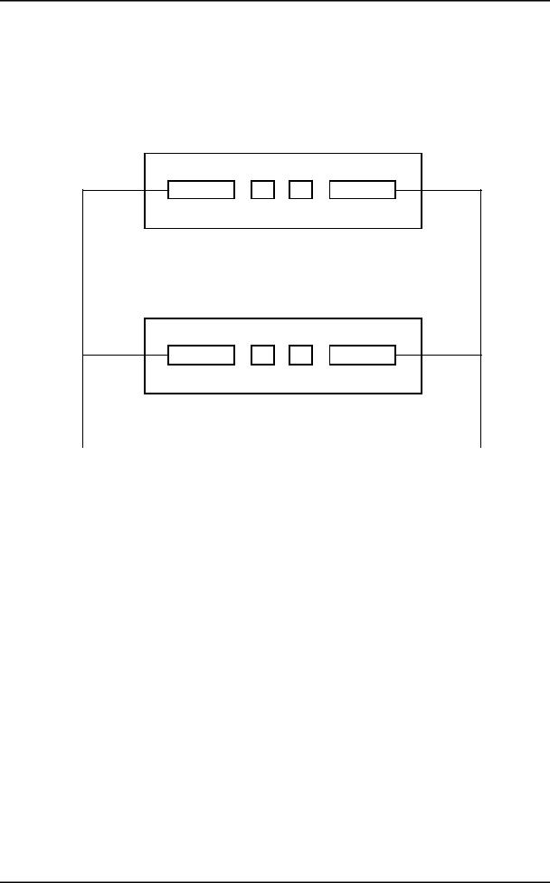
1.3.3.3 – Connecting with MSP operation
As EOW and AUX ports are physically integral with ADR IC1.x, operating the order wire and auxiliary channels with MSP protection requires the use of a "Y" cord electrically connecting, one by one, identically, the signals of EOW and AUX connectors.
EOW |
TR REC |
AUX |
ADR IC1.x Working |
|
|
EOW |
TR REC |
AUX |
ADR IC1.x Protection |
|
|
"Y" cord for |
|
"Y" cord for |
order wire |
|
auxiliary wire |
channel operation |
|
channel operation |
Likewise, in order to ensure a good behaviour during the changeover from one module to the other, the operator should take care to keep identical configurations on both ADR IC1.x cards; a warning message appears in case of modification.
Only the connections are not identical. There must be no connections on the "Protection" module, as in all the connections are made to the "Working" module.
Installation and User Guide - N56717020101
No reproduction or communication without the written consent of SAGEM SA Page A1-15
1 - INSTALLATION AND COMMISSIONING
1.3.4 - Connecting on ADR LAN1 card
|
ADR LAN1 |
|
|
|
|
|
|
|
|
|
|
|
|
10/100 HALF/FULL |
|
|
STATUS |
|
|
|
|
|
|
|
|
|
|
|
|
||
|
|
|
|
|
|
|
|
|
|
|
|
|
|||
|
|
|
|
|
|
|
|
|
|
|
|
|
|||
|
|
|
|
|
|
ETH |
|||||||||
|
|
|
|
|
|
||||||||||
|
|
|
|||||||||||||
LED |
STATUS |
||||||||||||||
HALF/FULL
Green |
Red |
|
ON |
OFF |
Card in service |
ON |
ON |
Card in alarm |
OFF |
OFF |
Hardware default (fuse) |
OFF |
ON |
Card out of service |
Flashing |
|
Autotest default |
ETH
|
Contact 1 |
|
Contact 8 |
|
|
1 |
: TX_ETH_TIP |
5 : NC |
|
||
2 |
: TX_ETH_RING 6 |
: RX_ETH_RING |
|
||
3 |
: RX_ETH_TIP 7 |
: NC |
NC : Reserved |
||
4 |
: NC |
8 |
: NC |
||
|
|||||
|
Yellow LED |
: link status |
|
||
|
ON |
: correct link |
|
||
|
Green LED |
: traffic status |
|
||
|
ON |
: on reception |
|
||
Yellow LED : Ethernet interface type (Half or Full Duplex)
ON |
: Full duplex |
10/100
Yellow LED : Ethernet interface bite rate
ON |
: 100 Mbit/s |
|
|
Figure 1-5 – Connecting ADR LAN1 card input |
|||
"ETH" Interface : |
|
|
|
|
|
Port |
Traffic Ethernet interface operating at 10 or 100 Mbit/s in half-duplex or full- |
||||
|
|
duplex mode according to the mode used by the interlocutor (dynamic |
|||
|
|
adaptation of the Ethernet port on each new log-in of the interlocutor), |
|||
Connector |
Ethernet 10 or 100 BaseT - RJ48 Type (Shielded RJ45). |
||||
|
|
|
Pin 1 |
Pin 8 |
|
|
|
|
|
Front view |
|
|
|
|
|
|
|
|
Pin N° |
|
Signal name |
|
Comments |
|
|
|
|
|
|
|
1 |
|
TX_ETH_TIP |
|
Ethernet output (hot point) |
|
|
|
|
|
|
|
2 |
|
TX_ETH_RING |
|
Ethernet output (cold point) |
|
3 |
|
RX_ETH_TIP |
|
Ethernet input (hot point) |
|
4 |
|
NC |
|
Reserved |
|
5 |
|
NC |
|
Reserved |
|
6 |
|
RX_ETH_RING |
|
Ethernet input (cold point) |
|
7 and 8 |
|
NC |
|
Reserved |
NOTE: Two LEDs are linked to the "ETH" interface:
• |
LED, "Activity", green colour |
: Trafic status indicator, |
• |
LED, "Link", yellow colour |
: Link status indicator. |
Electrical characteristics compliant with the IEEE 802.3U
Installation and User Guide - N56717020101
Page A1-16 No reproduction or communication without the written consent of SAGEM SA
1 - INSTALLATION AND COMMISSIONING
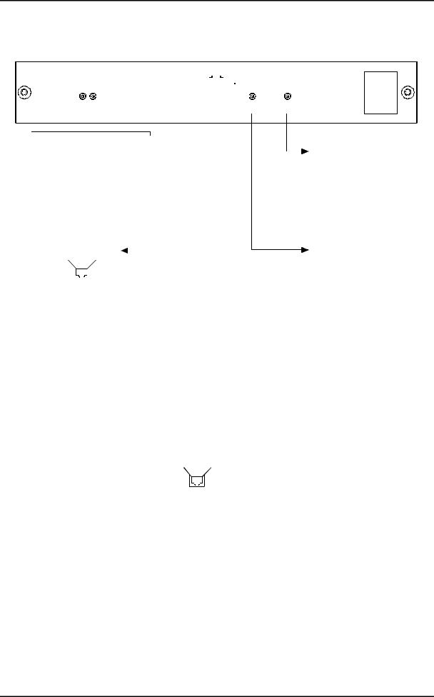
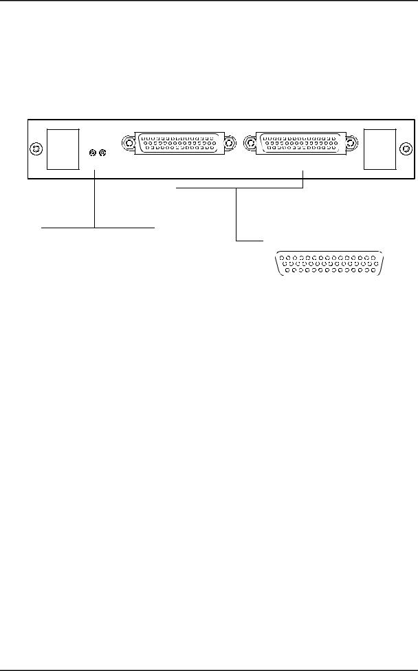
1.3.5 - Connecting on ADR 21E120 card
2 Mbit/s traffic connections, performed on "E1 INPUT" and "E1 OUTPUT" ports on the ADR21E120 card are identical with those performed on "E1 INPUT" and "E1 OUTPUT" ports on the front side of the motherboard (see § 1.3.2.4)
ADR 21E120
STATUS |
E1 OUTPUT |
LED |
|
STATUS |
Green |
Red |
|
ON |
OFF |
Card in service |
ON |
ON |
Card in alarm |
OFF |
OFF |
Hardware default (fuse) |
OFF |
ON |
Card out of service |
Flashing |
|
Autotest default |
E1 INPUT
 "E1 OUTPUT" and "E1 INPUT"
|
15 |
|
|
|
1 |
|
30 |
|
|
|
16 |
|
44 |
|
|
|
31 |
|
|
16 |
: GND |
|
|
1 |
: Tx(Rx) 1A |
17 |
: Tx(Rx) 2B |
31 |
: Tx(Rx) 1B |
2 |
: Tx(Rx) 3B |
18 |
: Tx(Rx) 3A |
32 |
: Tx(Rx) 2A |
3 |
: Tx(Rx) 4A |
19 |
: Tx(Rx) 5B |
33 |
: Tx(Rx) 4B |
4 |
: Tx(Rx) 6B |
20 |
: Tx(Rx) 6A |
34 |
: Tx(Rx) 5A |
5 |
: Tx(Rx) 7A |
21 |
: Tx(Rx) 8B |
35 |
: Tx(Rx) 7B |
6 |
: Tx(Rx) 9B |
22 |
: Tx(Rx) 9A |
36 |
: Tx(Rx) 8A |
7 |
: Tx(Rx) 10A |
23 |
: Tx(Rx) 11B |
37 |
: Tx(Rx) 10B |
8 |
: Tx(Rx) 12B |
24 |
: Tx(Rx) 12A |
38 |
: Tx(Rx) 11A |
9 |
: Tx(Rx) 13A |
25 |
: Tx(Rx) 14B |
39 |
: Tx(Rx) 13B |
10 |
: Tx(Rx) 15B |
26 |
: Tx(Rx) 15A |
40 |
: Tx(Rx) 14A |
11 |
: Tx(Rx) 16A |
27 |
: Tx(Rx) 17B |
41 |
: Tx(Rx) 16B |
12 |
: Tx(Rx) 18B |
28 |
: Tx(Rx) 18B |
42 |
: Tx(Rx) 17A |
13 |
: Tx(Rx) 19A |
29 |
: Tx(Rx) 20B |
43 |
: Tx(Rx) 19B |
14 |
: Tx(Rx) 21B |
30 |
: Tx(Rx) 21A |
44 |
: Tx(Rx) 20A |
15 |
: GND |
|
|
|
|
Figure 1-6 – Connecting ADR 21E120 card inputs
Installation and User Guide - N56717020101
No reproduction or communication without the written consent of SAGEM SA Page A1-17

1 - INSTALLATION AND COMMISSIONING
1.3.6 - 75 Ω connecting strip
Drafting TBD
Figure 1-7 - 75 Ω connecting strip
Installation and User Guide - N56717020101
Page A1-18 No reproduction or communication without the written consent of SAGEM SA

1 - INSTALLATION AND COMMISSIONING


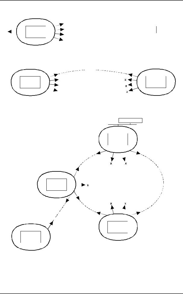
 LOCAL TEST


*case of underequipped unitary equipment
Equipment Inventory
- 48 V power Check
Aggregate optical loopback
Insertion of communication parameters (VT100)
Setting to time and insertion of the test configuration tributary accesses (HTTP browser)
Tributary Ports continuity check
- 48 V redundancy Check
A and B loops and alarms check
Local transmission test (30 mn) *
Optical connection
Connection of external sync input from of an "Master" equipment (optional)
|
Configuration Elaboration |
||
no |
|
|
|
Local Test on network |
|||
|
|||
|
of last équipment ? |
||
|
|
yes |
|
|
|
||
|
|
|
|
|
Link established |
||
Optical measurements
MSP protection check
Counters reset
24 H link Performance
Equipment operational (constitution of installation file)
Configuration Save
Figure 1-8 – Commissioning procedure for ADR155C network
Installation and User Guide - N56717020101
No reproduction or communication without the written consent of SAGEM SA Page A1-19

1 - INSTALLATION AND COMMISSIONING
1.4 - Commissioning
NOTE: The equipment can be operated from a PC fitted with VT100 emulation and HTTP navigator; its minimum configuration is defined in section 1.4.1.
A local terminal with VT100 emulation is indispensable during the first commissioning, in order to be able to access the equipment via the management function; however, this terminal only enables the communication function to be parameterized.
Procedure.
) On the first commissioning, the equipment scans its constitution and considers it as the expected configuration, in service, not monitored. It is thus advisable to insert the traffic cards before power-up, in order to speed up the commissioning.
)Switch on the power supply connected to the equipment.
)The equipment conducts self-tests:
SWhen self-tests have run correctly, the "ON" indicator light is illuminating,
SIn the opposite case, an indicator flashing code defines the faulty self-test (contact the hotline).
)Parameterize the communication interface, using the VT100 (see § 1.4.1).
)Using the HTTP navigator, (see § 1.4.3).
SUpdate the equipment time and date
SSet each card under monitoring: validate the "Monitoring" command.
)Connect the 2 Mbit/s and/or Ethernet ports, according to the equipment composition,
)Connect the AUX and EOW ports required.
)Download a predefined configuration or prepare the desired configuration, using the HTTP navigator:
SCreate the connections
SEstablish the wished protection (MSP protection, SNC protection ...)
SChoose the synchronization source, and change its parameters if required.
SChange, if necessary, the configuration parameters and the alarm configuration. The default configuration of the various parameters is provided by § 2.1.1.
)Conduct the tests on STM-1 links, complying with the process described in Figure 1-2.
)From that moment, the equipment is operational.
)Operating alarms can signal a wrong connection of interfaces. Check the connection of ports, the alarms corresponding to the connected ports, and correct any problems that may arise.
)Save configuration.
REMARK: It is possible, once the commissioning is performed, to connect additional 2 Mbit/s G.703, Ethernet or STM1 ports, and to insert or extract powered cards.
Installation and User Guide - N56717020101
Page A1-20 No reproduction or communication without the written consent of SAGEM SA
1 - INSTALLATION AND COMMISSIONING
|
|
|
|
H T T P |
|
|
|
Mngt port |
Application |
|
|
|
|||||||
|
|
E |
|
R |
|
|
P |
. ETH port |
. HTTP server |
R |
|
||||||||
|
|
T |
|
|
|
P |
|
||||||||||||
|
|
|
|
|
|
||||||||||||||
|
|
H |
|
|
|
P |
. 4 PPP ports |
. SNNP agent for |
Routing |
|
|||||||||
|
|
|
|
|
|
|
(Point to Point Protocol) |
|
|||||||||||
|
|
|
|
|
|
|
|
|
IONOS ANM |
function |
|
||||||||
|
|
|
|
S N M P |
|
|
|
|
|
|
|
|
|
|
|
||||
|
|
|
|
|
|
|
|
|
|
|
|
|
|
|
|
|
|
||
|
|
|
|
|
|
|
|
|
Communication function over an ADR 155C |
|
|
|
|||||||
|
|
|
|
|
|
|
|
D1 - D3 over STM1 |
D1 - D3 over STM1 |
|
|
|
|||||||
|
|
|
H T T P |
|
|
|
|
|
|
|
|
|
|
|
H T T P |
|
|||
E |
|
|
|
|
P |
|
x |
P |
|
|
E |
||||||||
|
|
R |
|
|
R |
|
|||||||||||||
T |
|
|
|
P |
|
x |
P |
|
T |
||||||||||
H |
|
|
|
P |
|
P |
|
H |
|||||||||||
|
|
|
|
|
|
|
|
|
x |
|
S N M P |
|
|||||||
|
|
|
S N M P |
|
|
|
|
|
|||||||||||
|
|
|
|
|
|
|
|
|
|
|
|
|
|
|
|||||
Example 1 : communication over a point to point link
IONOS ANM
|
The TPI can be connected to any |
|
|
|
E T H |
||||
|
S |
|
|
||||||
|
Ethernet interface as soon as the |
|
|
||||||
|
N |
|
R |
||||||
|
parameterezing enables to reach |
|
|||||||
|
1 equipment to be operated |
M |
|
||||||
|
|
|
|
|
|
P |
|
|
|
|
|
|
|
|
|
|
P P P |
||
|
|
|
|
|
|
|
|
|
|
|
|
|
|
|
|
D1 - D3 |
|
||
|
|
|
|
|
|
STM1 |
|
||
|
|
|
|
|
|
on West |
|
||
|
|
|
|
|
|
D1 - D3 STM1 |
|
||
|
|
|
|
H T T P |
|
on East |
|
||
|
|
E |
|
|
P |
|
|
|
|
|
|
|
R |
|
|
|
|
||
|
ADR |
H |
|
P |
|
|
|
|
|
|
T |
|
|
P |
|
|
|
|
|
|
|
|
|
|
|
D1 - D3 STM1 |
|
||
|
|
|
|
|
|
|
|||
|
|
|
|
S N M P |
|
on West |
|
||
IONOS ANM in necessary |
|
D1 - D3 |
|
||||||
to operate this FOT C |
|
|
D1 - D3 |
|
|||||
(but the ADR cannot be |
|
|
on STM1 |
STM1 |
|
||||
operated from the ETH |
|
|
tributary |
on East |
|
||||
interface of the FOT C |
|
|
|
|
|
|
|
||
|
FOT C * |
|
|
|
|
S |
|
|
P P P |
|
|
|
D1 - D3 |
|
|
|
|
||
|
|
|
|
|
|
|
|||
|
|
|
|
|
|
|
|||
|
|
|
|
|
N |
|
|
R |
|
|
|
|
|
on STM1 |
|
|
|||
|
|
|
|
|
M |
|
|
||
|
|
|
|
aggregate |
|
||||
|
|
|
|
|
|||||
E |
R |
|
P |
|
P |
|
|
||
|
|
|
E T H |
||||||
T |
|
P |
|
|
|
|
|||
H |
|
P |
|
|
|
|
|
||
S N M P
H
T ADR
T
P
D1 - D3 STM1
on East
D1 - D3
STM1 on West
H
T
T ADR
P
Example 2 : communication over an ADR 155C and FOT 155C ring
Figure 1-9 – Examples of the communication function configuration
Installation and User Guide - N56717020101
No reproduction or communication without the written consent of SAGEM SA Page A1-21

1 - INSTALLATION AND COMMISSIONING
1.4.1 - Configuration required
The minimum configuration proposed for the operating PC is as follows:
Description |
Configuration 1 |
|
Configuration 2 |
|
|
|
|
Processor |
|
266 MHz Pentium |
|
|
|
|
|
Memory |
32 MB |
|
64 MB |
|
|
|
|
Display |
800x600, 256 colours (1024x768 recommended) |
||
|
|
||
Interface |
Serial RS232 interface |
||
|
Ethernet 10 base T network card |
||
|
|
|
|
Operating system |
Windows 95 |
|
Windows NT4 |
|
|
|
|
Applications |
Hyperterminal for Windows |
||
|
HTTP navigator: Netscape Communicator 4.5 |
||
|
|
|
|
1.4.2 - Parameterizing the communication function
Figure 1-9 presents the available resources and various configurations possible for the communication function;
) Connect "COMM" port of the equipment to a "COM" port not used on the PC with VT100 emulation,
)Power the PC on,
)Start the Hyper Terminal application
Son the first use, proceed as follows:
Sconnect "COMM" port of the equipment to a "COM" port not used on the PC,
Spower the PC on,
Sselect, in succession, from Windows desktop, the Start, Programs, Accessories and HyperTerminal command buttons,
Schoose the icon representative of the HyperTerminal application,
Sa description window for the connection appears; give a name for the connection and validate your choices,
Sa new window appears; choose that PC "COM" port which is connected to the equipment and validate your choice,
Sa new window appears; configure the port parameters as indicated below and validate the programming :
S |
. Bits per second |
: 19200, |
S |
. Data bits |
: 8, |
S |
. Parity |
: no parity, |
S |
. Stop bits |
: 1, |
S |
. Flow control |
: none, |
Ssave the connection (Save command in the application File menu).
NOTE: On the next opening of "Hyperterminal" application, choosing the connection icon will be enough to be logged on the equipment.
On the equipment power-up, the operating menu appears.
To exit the "Hyperterminal" application, select Quit command from File menu.
Installation and User Guide - N56717020101
Page A1-22 No reproduction or communication without the written consent of SAGEM SA
Loading...