

Operation, Maintenance,
and Parts Manual
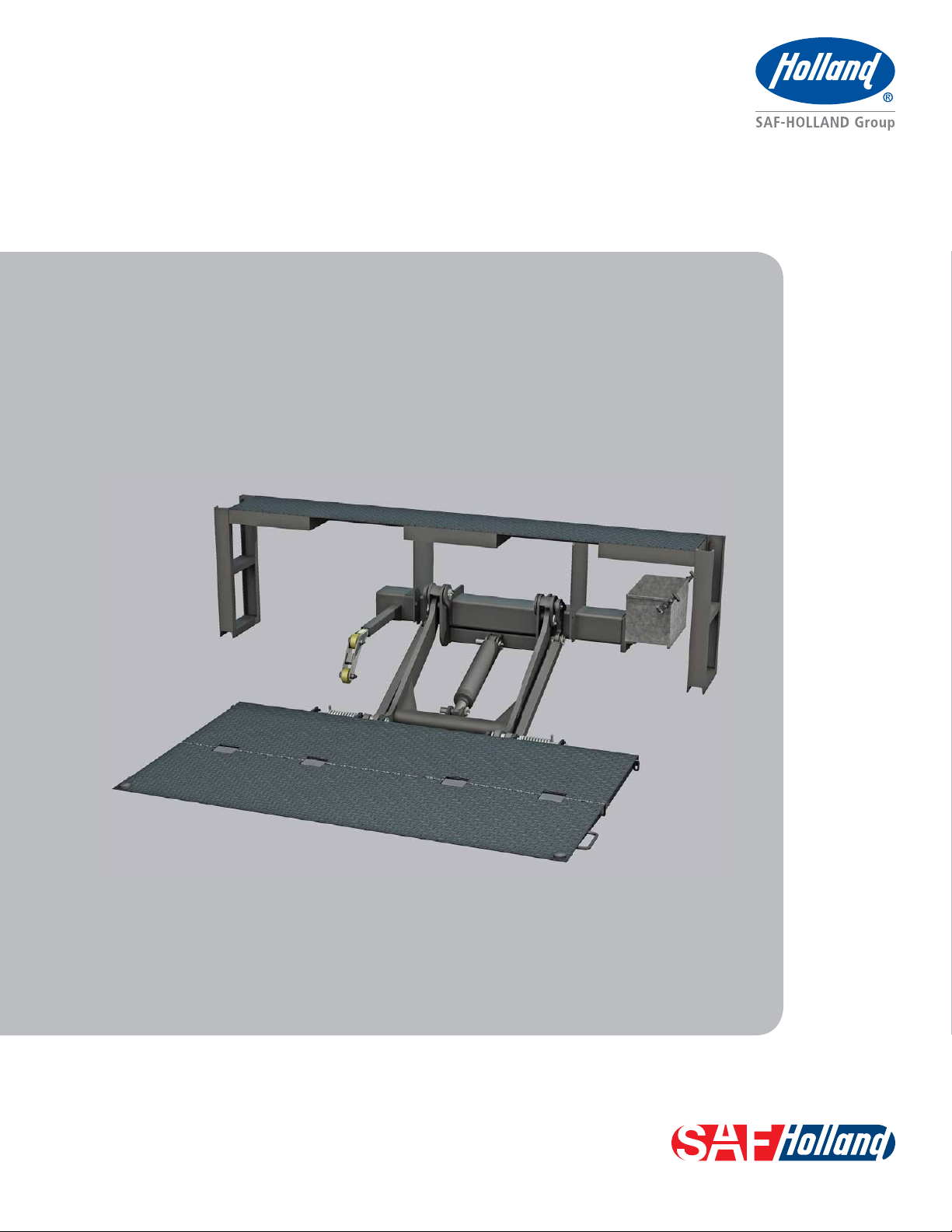
TLV Series Liftgate
• 2750 Lb. Capacity
XL-TG10156UD-en-US Rev A


Contents
Contents Page
Introduction ......................................................................... 3
Warranty .............................................................................. 3
Notes, Cautions, and Warnings ............................................. 3
Section 1 – General Safety Precautions ................................ 4
Section 2 – Model and Serial Number .................................. 6
Section 3 – Decal Part Numbers ........................................... 7
TLV Liftgate Terminology ...................................................... 8
Section 4 – Pre-Operation Information ................................. 9
Section 5 – Control Switch Operation ................................... 9
Section 6 – Raising or Lowering the Platform ..................... 10
Introduction
This manual provides you with the information necessary for
the care, maintenance, inspection, and safe operation of the
SAF-HOLLAND TL and TG Series Liftgate.
NOTE: For liftgate components replacement, contact
SAF-HOLLAND Customer Service at:
U.S. 888-396-6501
Canada 800-503-9847
Warranty
Refer to the complete warranty for the country in which
the product will be used. A copy of the warranty certificate
is included with the product as well as on the SAF-HOLLAND
website (www.safholland.us and www.safholland.ca). It may
also be ordered directly from SAF-HOLLAND; the address is
shown on the back cover.
Notes, Cautions, and Warnings
Contents Page
Section 7 – Unfolding the Platform .................................... 11
Section 8 – Platform Loading ............................................. 12
Section 9 – Stowing the Platform ....................................... 13
Section 10 – Filling the Hydraulic Reservoir ........................ 14
Section 11 – Routine Service and Inspection....................... 15
Section 12 – Troubleshooting ............................................. 16
Section 13 – Pump Hydraulic and Electrical Diagrams ......... 18
Section 14 – Pump Hydraulic and Electrical Schematic........ 20
Section 15 – Liftgate Components ...................................... 22
Section 16 – Hydraulic Components ................................... 24
IMPORTANT: Read this manual before using this
product. Keep this manual in a safe
location for future reference.
Failure to follow the instructions and
safety precautions in this manual can
result in death or serious injury.
Throughout this manual, you will notice the terms
“NOTE,” “IMPORTANT,” “CAUTION,” and “WARNING”
followed by useful product information. So that you may
better understand the manual, those terms are as follows:
NOTE: Includes additional information to enable
accurate and easy performance of procedures.
IMPORTANT: Includes additional information that if
not followed could lead to hindered
product performance.
You must read and understand all of the safety procedures presented
in this manual before operating or starting any work on the liftgate.
NOTE: In the United States, workshop safety requirements
are defined by federal and/or state Occupational
Safety and Health Act. Equivalent laws may exist
in other countries. This manual is written based
on the assumption that OSHA or other applicable
employee safety regulations are followed by the
location where work is performed.
Proper tools must be used to perform the maintenance and
repair procedures described in this manual. Many of these
procedures may require special tools.
XL-TG10156UD-en-US Rev A · 2013-04-18 · Amendments and errors reserved. © SAF-HOLLAND, Inc.
Used without the safety alert symbol,
indicates a potentially hazardous situation
which, if not avoided, could result in
property damage.
Indicates a potentially hazardous situation
which, if not avoided, could result in minor
or moderate injury.
Indicates a potentially hazardous situation
which, if not avoided, could result in death
or serious injury.
3
General Safety Precautions
1. General Safety Precautions
Read and observe all Warning and Caution hazard alert messages
in this publication. They provide information that can help
prevent serious personal injury, damage to components, or both.
Please observe the following safety instructions in order
to maintain the operational and road safety of your
SAF-HOLLAND Liftgate:
1. You must be fully trained on the capabilities and the limitations
of this equipment to operate the equipment properly.
2. When operating the liftgate, always stand to one side of
the platform. Make sure that the area is clear of obstacles,
other personnel, fingers, arms, hands, legs, and/or feet.
Failure to keep area near your liftgate
clear could create a crush and/or pinch
hazard which, if not avoided, could result
in death or serious injury.
IMPORTANT: DO NOT exceed liftgate capacity when
raising or lowering platform.
Failure to avoid overloading the liftgate
may result in platform failure which,
if not avoided, could result in death or
serious injury.
3. Make sure liftgate is in stowed position when not in use.
4. NEVER step off moving equipment. Only step off the
platform when it is in contact with the ground or at deck
height when entering the vehicle.
Failure to lower the platform to ground
level before stepping on or off platform
could result in mild to moderate injury.
We highly recommend the use of only SAF-HOLLAND
Original Parts.
A list of SAF-HOLLAND Technical Support locations to
supply SAF-HOLLAND Original Parts can be found at
www.safholland.us or by contacting SAF-HOLLAND
Customer Service at U.S. 1-888-396-6501 or Canada
1-800-503-9847.
Servicing Safety Precautions
1. DO NOT work underneath the liftgate without properly
supporting the raised platform and liftframe in
accordance with workplace safety requirements.
2. Never strike any part of the liftgate with a steel hammer.
3. Safety protection should always be worn as protection
from pressurized fluid spray, flying debris, and other
airborne matter when working with tools, power tools,
welding equipment, and dangerous chemicals.
NOTE: Never operate the liftgate with the vehicle running
unless instructed to by this manual for specific
service items.
Failure to turn off vehicle motor before
commencing work could allow vehicle to
move which, if not avoided, could result
in death or serious injury.
4. While servicing or repairing equipment, always disconnect
the electrical power to the pump motor and ensure that
the platform and liftframe is supported on the ground or
secured in the travel lugs.
5. Check for slippery surfaces before stepping off the
liftgate platform.
6. NEVER jump off the liftgate.
7. In an emergency situation, release the control switch to
stop the liftgate operation.
8. SAF-HOLLAND Liftgates require routine service, inspection,
and maintenance in order to maintain optimum performance,
proper operation, and to identify normal wear.
Failure to properly engage the vehicle
parking brake prior to operating or
maintaining liftgate may allow vehicle
movement which, if not avoided, could
result in death or serious injury.
4
XL-TG10156UD-en-US Rev A · 2013-04-18 · Amendments and errors reserved. © SAF-HOLLAND, Inc.
General Safety Precautions
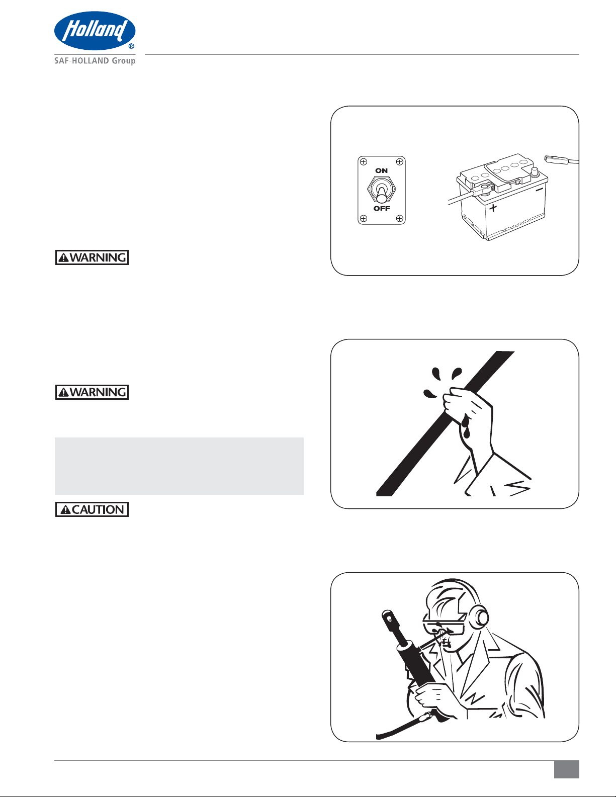
5. When welding is required, ensure that the battery ground
cable is disconnected and that all electrical equipment is
completely electrically isolated before welding is initiated
(Figure 1).
6. Before starting any welding, ensure that the area to be
repaired is cleaned of debris and combustible material.
Have a charged fire extinguisher available and know
how to use it.
7. When searching for an oil leak, wear work gloves and
use a piece of cardboard or wood as a detector. Wear a
safety face shield or goggles for eye protection. NEVER
use your bare hands to check for fluid leaks (Figure 2).
Failure to properly protect yourself when
searching for hydraulic leaks could result
in fluid injection into the skin which,
if not avoided, could result in death or
serious injury.
8. Pressure can remain in a hydraulic system after the power
source and pump have been shut down. Ensure that there
is no pressure in any of the hydraulic cylinders or hoses
before performing work on components, or disconnecting
any hoses (Figure 3).
Failure to depressurize the hydraulic
system could result in fluid injection into
the skin which, if not avoided, could
result in death or serious injury.
Figure 1
Figure 2
NOTE: Batteries contain acid that can burn and they
also produce gas that can explode, follow battery
manufacturers’ provided safety instructions when
working on your battery.
Failure to follow manufacturers’ safety
instructions when handling batteries may
result in explosion which, if not avoided,
could result in minor to moderate injury.
9. Inspect the equipment daily for potential fire hazards and
make any necessary repairs immediately.
10. Inspect electrical wiring and connections, and hydraulic
hose runs to ensure they are secure and not rubbing
against other components.
11. Clean up any excess grease, oil accumulation and spillage
immediately. Use only non-flammable products for cleaning
the liftgate or components.
Figure 3
XL-TG10156UD-en-US Rev A · 2013-04-18 · Amendments and errors reserved. © SAF-HOLLAND, Inc.
5
Model and Serial Number Information
2. Liftgate Model and Serial
Number Location
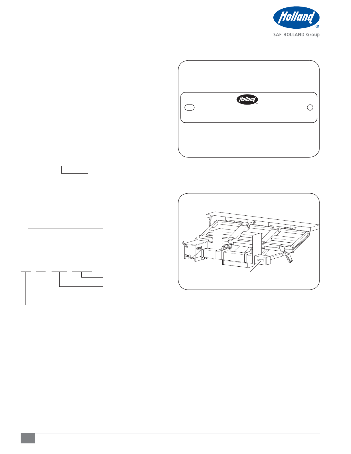
Each SAF-HOLLAND liftgate has a stamped metal tag that
identifies the liftgate model and serial number (Figure 4).
This tag is attached to the front roadside of the main tube
(Figure 5). In order to properly identify your HOLLAND
liftgate and its components when communicating with
SAF-HOLLAND or your dealer, please record the model, serial
numbers, dealer, and purcahse date and refer to them when
ordering replacement parts.
Model Number
TLV 27 48
Platform Size
48" long
Capacity
2,750 lbs.
Figure 4
Figure 5
MODEL NUMBER
XXXXXXXXXX-XXXX
SERIAL NUMBER
XXXXX
Model
Serial Number after November 1, 2008
98 02 312 0123
Sequence Number
Day of Year
Year Code
Facility Code
Equipment Model No.: _______________________________
Serial No.: _________________________________________
Purchase Date: _____________________________________
Dealer: ____________________________________________
LIFTGATE MODEL AND SERIAL
NUMBER TAG LOCATION
6
XL-TG10156UD-en-US Rev A · 2013-04-18 · Amendments and errors reserved. © SAF-HOLLAND, Inc.

Decal Requirements
3. Decal Part Numbers
IMPORTANT: All decals must be installed, maintained,
and kept visible and legible.
Prior to placing the vehicle into service, inspect all decals
listed below. Ensure the decals are in the correct location and
are legible (Figures 6 and 7). Replace any damaged and/or
missing decals.
It is the responsibility of the end user to periodically inspect
all decals and ensure that they are clean and completely
legible. If any decals are missing, loose, damaged, or difficult
to read, contact SAF-HOLLAND Customer Service to order
replacements immediately.
DECAL QTY ENGLISH FRENCH DESCRIPTION
A 2 XB-59726 XB-59727 Maximum Capacity 2,750
B 2 XB-51170 XB-57067 Pinch Point
C 1 XB-54995 XB-64388 High Pressure Fluid
D 1 XB-50346 XB-50353 Warning
Figure 6
CURBSIDE
A
Figure 7
C
E
F
D
B
G
ROADSIDE
B
E 1 XB-62815 XB-62878 Warning - Riding Platform
F 1 XB-50345 XB-50352 Instructions
G 1 XB-50344 XB-50349 Caution - Always Stand Clear
A
XL-TG10156UD-en-US Rev A · 2013-04-18 · Amendments and errors reserved. © SAF-HOLLAND, Inc.
7
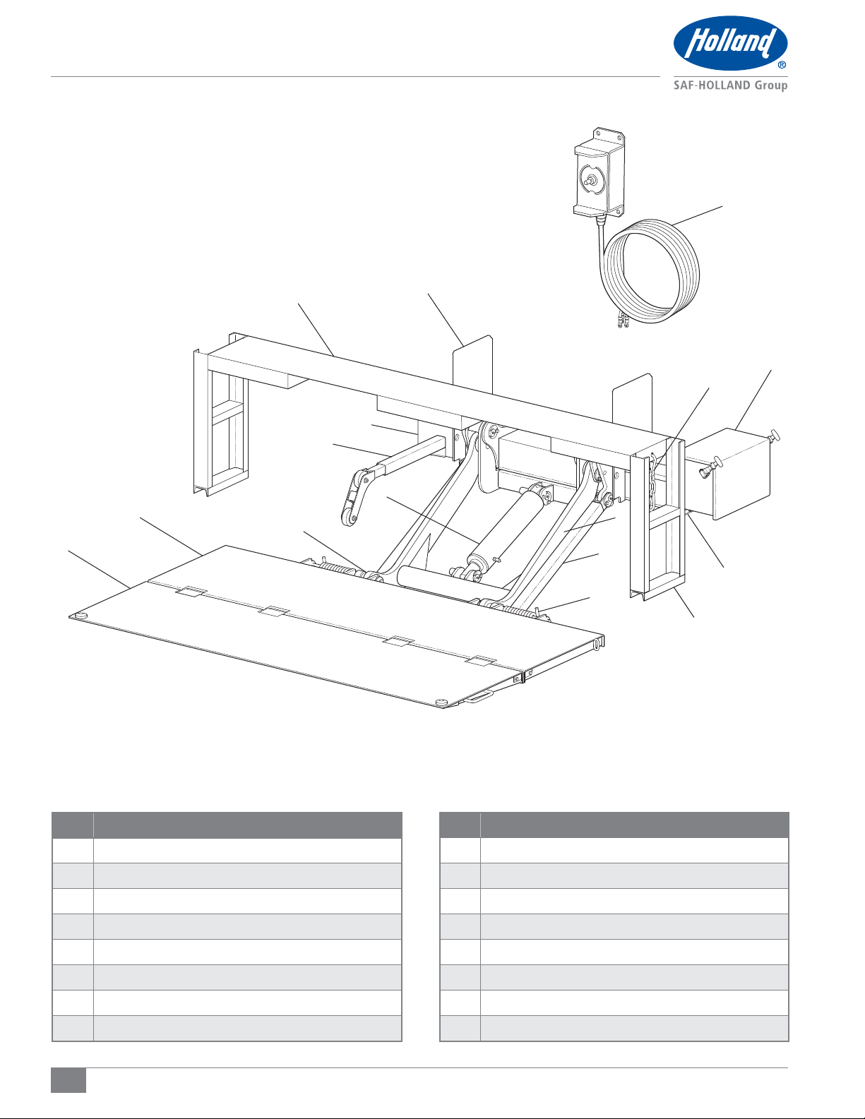
Liftgate Terminology
1
16
14
7
2
4
3
15
12
13
9
8
6
11
5
10
ITEM DESCRIPTION
Control Station
1
2 Inner Platform
3 Outer Platform
4 Adjusting Bolts
5 Torsion Spring
6 Compression Member
7 Roller Opener
8
Lift Frame
8
ITEM DESCRIPTION
9 Lift Cylinder
10 Step Brace
11 Pump Box Mount
12 Pump Box
13 Travel Hook
14 Main Tube
15 Attaching Plates
16
Deck Extension
XL-TG10156UD-en-US Rev A · 2013-04-18 · Amendments and errors reserved. © SAF-HOLLAND, Inc.
Liftgate Operation Instructions
4. Pre-Operation Information
1. Ensure the platform is clear of obstacles and other personnel.
2. Inspect liftgate for any damage, bruised paint or
bent components.
3. Inspect electrical cables and hydraulic hoses, repair or
secure as necessary.
Failure to repair and/or replace worn or
damaged components before use could
result in liftgate failure which, if not avoided,
could result in death or serious injury.
4. Read and understand the decals referenced in Section 3.
5. Vehicle must be on flat, level ground before operating liftgate.
6. Ensure that the vehicle parking brake is securely engaged.
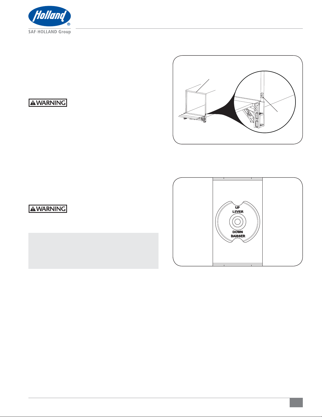
5. Control Station Switch Operation
To operate the liftgate, use the toggle switch on the control
station located at the rear of the vehicle (Figure 8).
This toggle switch enables the operator to raise and lower the
liftgate platform (Figure 9).
Figure 8
REAR OF VEHICLE
CONTROL
STATION
Figure 9
Failure to keep clear of the moving liftgate
could create a crush and/or pinch hazard
which, if not avoided, could result in death
or serious injury.
NOTE: If the Operator is required to ride the liftgate,
observe and familiarize yourself with the liftgate
operation, decals and manuals. Ensure stable
footing at all times. The switch only allows the
operator to raise or lower the platform.
XL-TG10156UD-en-US Rev A · 2013-04-18 · Amendments and errors reserved. © SAF-HOLLAND, Inc.
9

Liftgate Operation Instructions
6. Raising or Lowering the Platform
Failure to secure load prior to operating
platform could allow load to shift and
strike operator which, if not avoided,
could result in minor or moderate injury.
IMPORTANT: This unit is intended for loading and
unloading cargo only. If personnel are
required to ride the liftgate, familiarize
yourself with this liftgate manual.
Failure to ensure stable footing while
riding the liftgate could allow the
operator to fall which, if not avoided,
could result in death or serious injury.
6.1 Raising the Platform
1. Stand to the side of the vehicle and clear of the platform,
push the control station toggle switch in the UP direction
(Figure 10).
NOTE: The toggle switch must remain engaged for the
platform to continue moving upward.
2. To stop the platform from moving upward, release the
toggle switch.
Figure 10
CONTROL STATION
UP
TOGGLE SWITCH
Figure 11
CONTROL STATION
6.2 Lowering the Platform
1. Stand to the side of the vehicle and clear of the platform,
push the control station toggle in the DOWN direction
(Figure 11).
NOTE: The toggle switch must remain engaged for the
platform to continue moving downward.
2. To stop the platform from moving downward, release the
toggle switch.
DOWN
TOGGLE SWITCH
10
XL-TG10156UD-en-US Rev A · 2013-04-18 · Amendments and errors reserved. © SAF-HOLLAND, Inc.

Liftgate Operation Instructions
7. Unfolding the Platform
1. Stand clear of the liftgate, and using the control station,
raise the stowed platform to relieve any tension on the
travel chain (Figure 12).
2. Disengage the travel latch chain hook from the platform
(Figure 13).
3. With the travel chain clear, lower the unit until the
liftgate firmly contacts the ground.
Failure to ensure stable footing while
engaging the foot pedal could result
in slipping which, if not avoided, could
result in minor or moderate injury.
4. Grasp the platform to rotate it down. As the platform
starts to rotate, step back to allow the platform to fall
into a horizontal position (Figure 14).
Failure to keep feet clear of platform
during operation could create a crush
and/or pinch hazard which, if not avoided,
could result in death or serious injury.
5. While standing clear and to the side grasp the flip
over section and rotate it allowing it to fall into a
horizontal position.
Figure 12
CONTROL STATION
UP
TOGGLE SWITCH
Figure 13
TRAVEL LATCH
CHAIN HOOK
PLATFORM
XL-TG10156UD-en-US Rev A · 2013-04-18 · Amendments and errors reserved. © SAF-HOLLAND, Inc.
Figure 14
PLATFORM
11

Liftgate Operation Instructions
8. Platform Loading
Failure to keep load within platform edge
could create a crush hazard which, if not
avoided, may result in damage to the load.
Failure to keep loads stable and within
design capacity could result in falling objects
or component failure which, if not avoided,
could result in death or serious injury.
When riding the platform, failure to keep
feet within front edge of platform could
create a crush hazard which, if not avoided,
could result in death or serious injury.
8.1 Loading from the Ground
1. Using the control station, open the platform from the
stowed position and lower it to the ground (Refer to
Sections 6 and 7).
IMPORTANT: Never operate a fork lift truck on or over
the platform.
Failure to remove fork lift trucks from
the liftgate platform area could cause
component failure which, if not avoided,
could result in death or serious injury.
2. Load the platform by placing the load center as close to the
center of the platform as possible and placing the heaviest
part of the load to the front of the platform (Figure 15).
3. Using the control station toggle switch at the rear of the
vehicle, raise the platform to deck height and unload
(Figure 16). If required, repeat procedures to continue
with additional loads.
4. When the liftgate has been unloaded, lower and stow the
platform (Refer to Sections 6 and 9).
Figure 15
PLACE LOAD
ON CENTER
OF PLATFORM
FRONT OF
PLATFORM
Figure 16
DECK HEIGHT
8.2 Loading from the Vehicle
1. Using the control station, open and raise the platform to
deck height (Refer to Sections 6 and 7).
2. Load the platform by placing the load center as close to the
center of the platform as possible and placing the heaviest
part of the load to the front of the platform (Figure 17).
IMPORTANT: Never operate a fork lift truck on or over
the platform.
Failure to remove fork lift trucks from
the liftgate platform area could cause
component failure which, if not avoided,
could result in death or serious injury.
3. Using the control station toggle switch on the rear of the
vehicle, lower the platform to the ground.
4. When the liftgate has been unloaded, stow the platform
(Refer to Section 9).
12
Figure 17
PLACE LOAD
ON CENTER
OF PLATFORM
FRONT OF PLATFORM
XL-TG10156UD-en-US Rev A · 2013-04-18 · Amendments and errors reserved. © SAF-HOLLAND, Inc.

Liftgate Operation Instructions
9. Stowing the Platform
1. Lower the platform to below waist level, lift the end of
the flipover section, rotating it about the pivot bolts and
allow the flipover to fall onto the platform (Figure 18).
Failure to keep feet clear of platform
during operation could create a crush
and/or pinch hazard which, if not avoided,
could result in death or serious injury.
2. Lower the platform to the ground and rotate the inner
platform allowing it to rest against the platform roller
openers (Figure 19).
3. Stand clear and using the control station, raise the
platform until the platform is in fully raised position.
NOTE: When the liftgate is fully retracted to the stored
position, release the control switch.
4. Position the travel latch chain hook into the latch hook
hole in the side of the platform (Figure 20).
Figure 18
FLIPOVER
SECTION
PIVOT BOLTS
Figure 19
XL-TG10156UD-en-US Rev A · 2013-04-18 · Amendments and errors reserved. © SAF-HOLLAND, Inc.
ROLLER OPENERS
Figure 20
HOLE IN
PLATFORM
TRAVEL
LATCH
HOOK
13

Filling the Hydraulic Reservoir
10. Filling the Hydraulic Reservoir
IMPORTANT: Keep dirt, water, and other contaminants
from entering the hydraulic system; clean
the area to prevent contamination of the
hydraulic fluid and use a clean funnel with
a fine screen mesh.
1. Set the vehicle parking brake.
2. Using the control station, put the platform in the down
and open position (Figure 21).
3. Remove the filler cap and add recommended hydraulic
fluid to pump reservoir. Check that the hydraulic fluid is
at the proper fill level, half full (Figure 22).
IMPORTANT: Always use the correct grade of hydraulic
fluid. Refer to the chart below for
recommended hydraulic fluid or contact
your SAF-HOLLAND representative.
TEMPERATURE RECOMMENDED FLUIDS
RANGE MANUFACTURER TYPE
Above 0° C
(32° F)
-25 to 65° C
(-15 to 150° F)
-35 to 50 ° C
(-30 to 120° F)
-45 to 40° C
(-50 to 100° F)
Any
Any Esso, Exxon
Mobil, Shell
Exxon, Esso Shell,
Petro--Can
Any Esso, Exxon,
Shell
AW-32
ISO 32
HYDRAUL 50
DTE 11
DONAX TD
Low Viscosity
UNIVIS N15
TELLUS T15
MV ARCTIC 15
MIL-H-5606
UNIVIS J-13
UNIVIS HV1 13
FLUID #4
Figure 21
TLV MODEL IN
DOWN AND OPEN
POSITION
Figure 22
FILLER CAP
14
XL-TG10156UD-en-US Rev A · 2013-04-18 · Amendments and errors reserved. © SAF-HOLLAND, Inc.

11. Routine Service and Inspection
11.1 Daily Inspection
1. Daily or before each trip, inspect the liftgate for damage
to mounting assemblies, mechanical parts, and hydraulic
components and hoses. Any noticeable defects must be
repaired prior to operation to avoid damage and possible
injury. Inspect and verify the condition of the following
key components:
• Torsion springs – are not broken or rusted
• Stowage lock mechanism – is in working order
• Attaching plates – no bends and/or cracked welds
are present
• Deck extension – no cracked welds are present
• Pivot points – no pin movement caused by excessive wear
• Pivot points – all pins and bushings are present and in
good working order
• Shackles – are in proper orientation and proper
platform presentation
• Platform – no bends are present
• Platform – no weld cracks are present
• Flipover – no bends are present
• Flipover – no weld cracks are present
• Control switch – is in properly operational
• Control switch – no damage is present
• Control switch – have no noticeable corrosion
• Hydraulic hoses – have no leaks
• Hydraulic hoses – are secured properly
• Hydraulic hoses – no rub or abrasion marks are present
• Cylinders – have no leaks
• Cylinders – no damage is present
2. Inspect and replace any decals that have been removed
or have become illegible.
11.2 Monthly Inspection
1. Every 1000 cycles or 30 days, whichever occurs first, lubricate
all pivot points using EP2 chassis grease. In severe winter
conditions, it may be necessary to lubricate more frequently.
2. Lubricate linkage pivot points with light spray lubricant.
3. Check oil level in reservoir (1/2" [13 mm] from top of
tank with cylinders retracted).
4. Verify electrical connections, coat with non aerosol
dielectric grease or equivalent.
Routine Service and Inspection
2. Lubricate linkage pivot points with light spray lubricant.
3. Inspect all decals. Replace any decals that are not clearly
visible or legible.
11.4 Alternate Year Inspection
1. Every 24,000 cycles or two (2) years, whichever occurs
first, inspect all pivot points for wear. Replace any pins
or parts that show signs of wear.
2. Replace any worn hydraulic hoses, leaking fittings or
leaking cylinders.
IMPORTANT: Review General Safety Precautions before
working on hydraulic or electrical components.
11.5 Monthly Hydraulic and Electrical Inspection
1. Inspect and remove the coil from the valve and look for signs of
corrosion. If corrosion is present, clean and repair as necessary.
2. Inspect to ensure all hydraulic hoses are tight and not
leaking. If hoses are showing signs of wear, replace as
necessary. After torquing the hydraulic hoses, SAF-HOLLAND
recommends putting a line across the fittings for a future
visual reference that will indicate loose fittings.
3. Inspect the filler cap for signs of damage. The foam baffle
on the inside of the cap should be flat and in place. Inspect
all wire connections on toggles, push buttons or any other
controls attached to the liftgate. Clean and apply dielectric
grease to all electrical components to help reduce corrosion.
4. Inspect all wiring and wiring connections to ensure they
are tight and free of corrosion. If the pump has foreign
debris, clean the entire pump and wire connections. Once
you are satisfied that all components are clean, apply
non-aerosol dielectric grease to all connections. If any
wires show signs of deterioration, replace as required.
5. SAF-HOLLAND recommends that you flush and replace
the hydraulic oil every year to ensure contaminates are
flushed from the system. Remove the pump tank and
wipe free with a lint free cloth. If present, clean reservoir
magnet of contaminants. Remove the strainer and flush.
Replace the strainer. Remove any contaminates.
NOTE: To reduce downtime, bring in your liftgate every
two to three (2-3) months for quick and simple
inspections. Daily inspections while doing the circle
check on your vehicle will spot any concerns
before they become serious failures.
11.3 Yearly Inspection
1. Change the oil and oil filter. When filling pump reservoir, use
a funnel with a fine mesh screen . Use only recommended
hydraulic fluid (refer to Section 15).
XL-TG10156UD-en-US Rev A · 2013-04-18 · Amendments and errors reserved. © SAF-HOLLAND, Inc.
15

Troubleshooting
12. Troubleshooting
PROBLEM POSSIBLE CAUSE RESOLUTION
Platform lowers slowly or does not lower.
Flow control valve incorrectly installed. Check location and direction of arrow on valve.
Electrical connections loose, disconnected or corroded. Check connections and wire condition.
Battery does not have enough voltage to activate
solenoid properly.
Restriction/blockage of hydraulic hose.
Flow control valve blocked. Clean or replace valve.
Mechanical components seized or damaged.
Incorrect or contaminated oil in system.
Hydraulic system not plumbed properly.
Verify voltage and recharge or replace battery.
Ensure that cables are in good condition with
secure connections.
Check hoses for external damage or pinching.
Check for blockages in hoses.
Lubricate all pivot points and replace all
damaged items.
Oil should be clean and for the appropriate
geographical climate.
Check to see that the hose connected to the ‘A’
port is plumbed to the rod end of the cylinder.
Unit will not lift capacity load.
Oil expels from reservoir while loading.
Pump will not operate.
Hydraulic cylinder leaking internally. Replace seals or complete cylinder.
Relief valve setting too low. Adjust relief valve setting.
Hydraulic pump worn. Change worn parts or pump.
Too much oil in reservoir. Ensure level of oil allows displacement of rods.
Wrong flow control fitting.
Motor is not running when lowering platform.
(Power down option only)
Master disconnect switch is turned off Verify the main power is turned on.
Battery does not have enough voltage/current.
Electrical wiring to pump is loose, disconnected
or corroded
Remote control switch broken or shorted. Check wiring to switch.
Solenoid switch on pump faulty. Check solenoid switch.
Electrical coupling to trailer not complete
(Tractor/Trailer vehicles only).
Check that the number stamped on flow control
valve is correct as per the appropriate schematic.
Check for power at the "down" coil
Verify voltage and recharge or replace battery.
Ensure that cables are in good condition with
secure connections.
Check wiring to pump.
Connect coupling.
16
XL-TG10156UD-en-US Rev A · 2013-04-18 · Amendments and errors reserved. © SAF-HOLLAND, Inc.

Troubleshooting
PROBLEM POSSIBLE CAUSE RESOLUTION
Verify voltage and recharge or replace battery.
Battery does not have enough voltage/current.
Insufficient oil in reservoir.
Defective actuating coil on valve. Replace actuating coil.
Liftgate is overloaded. Reduce the load on the platform.
Ensure that cables are in good condition with
secure connections.
With platform on ground, fill tank within 2" (50 mm)
of top with Dextron III Automatic Transmission Fluid.
Platform will not raise.
Platform will not raise smoothly.
Platform creeps down when stationary.
Hose or fitting leak. Check and re-torque fittings.
Leaking check valve or relief valve. Clean, adjust or replace valve.
Worn piston seals. Replace seals.
Worn or scored piston. Replace cylinders.
Pivot points seized. Lubricate.
Pump is worn out. Replace pump.
Broken pump shaft or coupler. Replace shaft or coupling as necessary.
Insufficient oil in reservoir. Fill reservoir.
Operate ‘Raise Control’ for a few seconds at
Air lock in hydraulic system.
Undue mechanical wear or lack of lubrication. Lubricate pivots, replace worn parts.
Cylinder seal leak. Replace seals or cylinder if scored.
Worn or dirty check valve. Clean or replace valve.
Hose or fitting leak Replace hose or tighten fitting
Battery does not have enough voltage/current.
Liftgate is overloaded. Reduce load on platform.
top of stroke. Repeat two (2) times, pausing
between operations.
Verify voltage and recharge or replace battery.
Ensure that cables are in good condition with
secure connections.
Faulty cable connections: Electrical connections
corroded or disconnected.
Platform raises slowly.
XL-TG10156UD-en-US Rev A · 2013-04-18 · Amendments and errors reserved. © SAF-HOLLAND, Inc.
Pump motor not grounded adequately. Check grounding to truck frame.
Hose leaking. Tighten or replace hoses.
Cylinder internal leak. Replace seals or replace cylinder.
Lack of lubrication or undue mechanical wear. Lubricate all pivot points and replace worn parts.
Incorrect relief valve setting. Check relief valve setting.
Worn pump. Replace pump.
Check connections.
17

Pump Hydraulic and Electrical Diagram
13. Pump Hydraulic and Electrical Diagrams
Power Down Option
Figure 23
A PORT (C1) (UP)
(TOP VIEW)
BLACK WIRE
FROM CONTROL
(2W2P) (DOWN)
B PORT (C2) (DOWN)
(SIDE VIEW)
WHITE WIRE FROM TOGGLE (4W2P) (UP)
POWER FROM BATTERY
(END VIEW)
POWER FROM
CONTROL (GREEN)
18
XL-TG10156UD-en-US Rev A · 2013-04-18 · Amendments and errors reserved. © SAF-HOLLAND, Inc.

Gravity Down Option
Figure 24
Pump Hydraulic and Electrical Diagram
OUTLET PORT
(TOP VIEW)
BLACK WIRE FROM
CONTROL (DOWN)
POWER FROM CONTROL
(GREEN)
POWER FROM BATTERY
(SIDE VIEW)
WHITE WIRE FROM
TOGGLE (UP)
(END VIEW)
XL-TG10156UD-en-US Rev A · 2013-04-18 · Amendments and errors reserved. © SAF-HOLLAND, Inc.
19

Pump Hydraulic Schematic
14. Pump Hydraulic and Electrical Schematic
Power Down Option
Figure 25 (Hydraulic Schematic)
34 BAR
500 PSI
A (UP)B (DOWN)
BLACK WIRE
(2W2P)
WHITE WIRE
(4W2P)
Figure 26 (Electrical Schematic)
193 BAR
2800 PSI
1.98 CC/REV
0.121 IN3/REV
2W2P
VALVE
COIL FLOW
PORT B
BLACK (DOWN)
FLOW PORT B
MOTOR START
SOLENOID
GREEN (POWER)
20
WHITE (UP)
FLOW PORT A
4W2P VALVE COIL FLOW PORT A
+ 12V DC BATTERY(+VE)
XL-TG10156UD-en-US Rev A · 2013-04-18 · Amendments and errors reserved. © SAF-HOLLAND, Inc.

Gravity Down Option
Figure 27 (Hydraulic Schematic)
OUTLET PORT
3/8-19 BSPP REF
172 BAR
2500 PSI
Pump Hydraulic Schematic
7.57 LPM
2.0 GPM
Figure 28 (Electrical Schematic)
2.31 CC/REV
0.137 TN3/REV
2W2P
VALVE
COIL
BLACK (DOWN)
MOTOR START
SOLENOID
GREEN (POWER)
WHITE (UP)
+ 12V DC BATTERY(+VE)
XL-TG10156UD-en-US Rev A · 2013-04-18 · Amendments and errors reserved. © SAF-HOLLAND, Inc.
21

Liftgate Assembly - Exploded View
15. Liftgate Components
23
25
(30 1/2") (29 1/2")(30") (28 3/4")
26
31
28
24
22
21
14
20
16
7
10
9
8
18
17
12
5
4
3
2
1
13
6
19
27
30
29
22
XL-TG10156UD-en-US Rev A · 2013-04-18 · Amendments and errors reserved. © SAF-HOLLAND, Inc.

Liftgate Assembly - Parts Lists
TLV 2748W
DETAIL DESCRIPTION
1 Outer Platform Assembly XB-59906-28 XB-59906-28 1
2 Pin XB-59906-49 XB-59906-49 4
3 Connector XB-59906-48 XB-59906-48 4
4 Inner Platform Assembly XB-59906-29 XB-59906-29 1
5 Shackle, Curbside XB-59906-34 XB-59906-34 2
6 Spring, Curbside XB-59906-46 XB-59906-46 1
7 Spring, Roadside XB-59906-47 XB-59906-47 1
8 Lock Plate, Pin XB-59906-45 XB-59906-45 2
9 Lock Plate, Pin XB-59906-44 XB-59906-44 2
10 Adjunct-Arm XB-59906-33 XB-59906-33 2
11 Spacer XB-59906-38 XB-59906-38 2
12 Spacer XB-59906-39 XB-59906-39 2
13 Hose, Gravity Down XB-59906-54 N/A 1
14 Lock Plate, Pin XB-59906-43 XB-59906-43 2
15 Lift Frame XB-59906-32 XB-59906-32 1
16 Cylinder XB-59906-50 2046100000180 1
17 Pin XB-59906-31 XB-59906-31 2
18 Right Angle Return Air Joint XB-59906-30 XB-59906-30 1
19 Bracket, Cylinder & Lift Arm XB-59906-35 XB-59906-35 1
20 Spacer XB-59906-37 XB-59906-37 2
21 Lock Plate, Pin XB-59906-41 XB-59906-41 2
22 Lock Plate, Pin XB-59906-42 XB-59906-42 2
23 Mounting Plate XB-59906-51 XB-59906-51 1
24 Insert, Roller Opener 2112360004130 2112360004130 1
25 Install Strap, Long XB-59906-52 XB-59906-52 1
26 Install Strap, Short XB-59906-53 XB-59906-53 1
27 Lock Chain Assembly XB-59906-40 XB-59906-40 1
28 Extension Plate 2112200003560 2112200003560 1
29 Pump Box 2112360003570 AK-62864-01 1
30A 2" Step Bumper XA-50044 XA-50044 2
30B 3" Step Bumper XA-50045 XA-50045 2
31 Shackle, Roadside XA-55906-55 XA-55906-55 1
GRAVITY DOWN
TLV 2748W
POWER DOWN QTY
XL-TG10156UD-en-US Rev A · 2013-04-18 · Amendments and errors reserved. © SAF-HOLLAND, Inc.
23

Hydraulics Part List
16. Hydraulic Components
Gravity Down Option
6
5
4
3
2
1
7
DETAIL DESCRIPTION PART NO. QTY
1 90° Fitting, Air Hose XB-59906-30 1
2 Air Hose, Gravity Down XB-59906-54 1
3 Fitting, 90° Elbow, -6 Orb / 1/4" Fnpt XB-57030 1
4 Flow Control Valve, 2.0 Gpm XB-50032 1
5 Adapter 1/4" Male Pipe/-4 Male Jic XB-51529 1
6 Hose Asssembly, 60" Lg XA-51610-60 1
7 Control Station XA-58359-01 1
24
XL-TG10156UD-en-US Rev A · 2013-04-18 · Amendments and errors reserved. © SAF-HOLLAND, Inc.

Power Down Option
Hydraulics Parts List
1
6
3
4
5
2
7
DETAIL DESCRIPTION PART NO. QTY
1 Fitting, 90° Elbow, -6 Orb / -4 Jic XB-51918 1
2 Hose Assembly, 60" Lg XB-59906-60 1
3 Fitting, 90° Elbow, -6 Orb / 1/4" Fnpt XB-57030 1
4 Flow Control Valve, 2.0 Gpm XB-50032 1
5 Adapter 1/4"Male Pipe/-4 Male Jic XB-51529 1
6 Hose Assembly, 72" Lg XA-51610-07200 1
7 Control Station XA-58359-01 1
XL-TG10156UD-en-US Rev A · 2013-04-18 · Amendments and errors reserved. © SAF-HOLLAND, Inc.
25

Notes
26
XL-TG10156UD-en-US Rev A · 2013-04-18 · Amendments and errors reserved. © SAF-HOLLAND, Inc.

Notes
XL-TG10156UD-en-US Rev A · 2013-04-18 · Amendments and errors reserved. © SAF-HOLLAND, Inc.
27

From fifth wheel rebuild kits to suspension bushing repair kits,
SAF-HOLLAND Original Parts are the same quality components used
in the original component assembly.
SAF-HOLLAND Original Parts are tested and designed to provide
maximum performance and durability. Will-fits, look-alikes or, worse
yet, counterfeit parts will only limit the performance potential and
could possibly void SAF-HOLLAND’s warranty. Always be sure to spec
SAF-HOLLAND Original Parts when servicing your
SAF-HOLLAND product.
SAF-HOLLAND USA
www.safholland.us
SAF-HOLLAND CANADA
WESTERN CANADA
www.safholland.ca
SAF-HOLLAND MEXICO
www.safholland.com.mx
info@safholland.com
SAF-HOLLAND USA, INC.
1950 Industrial Blvd., Muskegon, MI 49442
www.safholland.com
888.396.6501
·
519.537.3494
·
604.574.7491
·
52.55.5362.8743
·
Fax 800.356.3929
·
Fax 800.565.7753
·
Fax 604.574.0244
·
Fax 52.55.5362.8743
·
XL-TG10156UD-en-US Rev A · 2013-04-18 · Amendments and errors reserved. © SAF-HOLLAND, Inc.
 Loading...