


Service Manual for Drum Brake Axles
Tapered and Parallel Spindle Axles
XL-TA10006OM-en-US Rev B
Contents
Contents |
Page |
Introduction......................................................................... |
3 |
Warranty.............................................................................. |
3 |
Notes, Cautions, and Warnings ............................................. |
3 |
Section 1 – General Safety Instructions ................................ |
4 |
Section 2 – Model Identification........................................... |
5 |
Section 3 – Identification Tag ............................................... |
5 |
Brake Components Parts List Prior to November 30, 2012..... |
6 |
Brake Components Parts List After November 30, 2012......... |
7 |
Section 4 – Hubs, Bearings and Seal Removal....................... |
8 |
Section 5 – Bearing Inspection ........................................... |
10 |
Section 6 – Hubs, Bearings and Seal Installation................. |
11 |
Section 7 – Hub Bearing Adjustment .................................. |
13 |
Section 8 – Hub Cap Installation ........................................ |
15 |
Section 9 – Filling Hub with Lubricant (Oil Based) .............. |
15 |
Contents |
Page |
Section 10 – Retracting the Brake Shoes or Slack |
|
Adjuster Control Arm(s).................................. |
16 |
Section 11 – Brake Shoe Removal ...................................... |
17 |
Section 12 – Brake Shoe Installation .................................. |
19 |
Section 13 – Brake Adjuster Removal ................................. |
22 |
Section 14 – Brake Adjuster Installation ............................. |
22 |
Section 15 – S-Camshaft and Bearing Removal Procedure... |
23 |
Section 16 – S-Camshaft and Bearing Installation .............. |
24 |
Section 17 – Brake Adjustment Procedure .......................... |
26 |
Section 18 – ABS Sensor Replacement Procedure ............... |
27 |
Section 19 – Axle Alignment Inspection.............................. |
27 |
Section 20 – Routine Service Schedule ............................... |
28 |
Section 21 – Torque and Lubrication Specifications............. |
29 |
Section 22 – Troubleshooting Chart .................................... |
30 |
Introduction
This manual provides the necessary information for the maintenance, inspection, and safe operation of the SAF® axle/brake system.
Read this manual before using or servicing this product and keep it in a safe location for future reference. Updates to this manual, which are published as necessary, are available on the internet at www.safholland.us.
Use only SAF-HOLLAND® Original Parts to service your SAF-HOLLAND INTEGRAL™ disc brake axle. A list of technical support locations that supply SAF-HOLLAND® Original Parts and an Aftermarket Parts Catalog are available on the internet at www.safholland.us or contact Customer Service at 888-396-6501.
Warranty
Refer to the complete warranty for the country in which the product will be used. A copy of the written warranty is included with the product or available on the internet at www.safholland.us.
Notes, Cautions, and Warnings
Before starting any work on the unit, read and understand all the safety procedures presented in this manual. This manual contains the terms “NOTE”, “IMPORTANT”, “CAUTION”, and “WARNING” followed by important product information. These terms are defined as follows:
NOTE: Includes additional information to enable accurate and easy performance of procedures.
IMPORTANT: Includes additional information that if not followed could lead to hindered product performance.
Used without the safety alert symbol, indicates a potentially hazardous situation which, if not avoided, could result in property damage.
Indicates a potentially hazardous situation which, if not avoided, could result in minor or moderate injury.
Indicates a potentially hazardous situation which, if not avoided, could result in death or serious injury.
XL-TA10006OM-en-US Rev B · 2014-03-13 · Amendments and Errors Reserved · © SAF-HOLLAND, Inc., SAF-HOLLAND, HOLLAND, SAF, |
3 |
and logos are trademarks of SAF-HOLLAND S.A., SAF-HOLLAND GmbH, and SAF-HOLLAND, Inc. |
|
|
General Safety, Maintenance and Inspection Instructions
1. Safety Instructions
General and Servicing Safety Instructions
Read and observe all Warning and Caution hazard alert messages. The alerts provide information that can help prevent serious personal injury, damage to components, or both.
Failure to follow the instructions and safety precautions in this manual could result in improper servicing or operation leading to component failure which if not avoided could result in death or serious injury.
All installation should be performed by a properly trained technician using proper/special tools, and safe procedures.
NOTE: In the United States, workshop safety requirements are defined by federal and/or state Occupational Safety and Health Act (OSHA). Equivalent laws could exist in other countries. This manual is written based on the assumption that OSHA or other applicable employee safety regulations are followed by the location where work is performed.
IMPORTANT: Use only SAF-HOLLAND® Original Parts to service your SAF-HOLLAND® INTEGRAL™
disc brake axle.
Failure to maintain your SAF-HOLLAND® INTEGRAL™ disc brake with SAF-HOLLAND® Original Parts can result in brake or wheel bearing failure which, if not avoided, could result in death or serious injury.
Properly support and secure the vehicle and axles from unexpected movement when servicing the unit.
Failure to properly support the vehicle and axles prior to could create a crush hazard which, if not avoided, could result in death or serious injury.
If possible, unload the trailer before performing any service procedures.
After re-positioning the brake chamber, brake adjuster and/or ABS system as instructed in this manual, ALWAYS consult the manufacturer’s manual for proper operation.
IMPORTANT: Key components on each axle system including but not limited to suspension, brake adjuster, brake chambers, bearings, hubs, and drums require information supplied by the original manufacturer of the components to ensure proper and safe operation of the axle system.
Failure to follow the original manufacturer’s instructions regarding spring brake or air pressure control could allow an uncontrolled release of energy which could result in death or serious injury.
Service both roadside and curbside of an axle. Worn parts should be replaced in sets. Key components on each axle’s braking system, such as friction material, rotors and drums will normally wear over time.
Operational and Road Safety Instructions
The wheel contact surfaces between the wheel and hub MUST NOT receive additional paint.
IMPORTANT: The wheel contact surfaces MUST be clean, smooth and free from grease.
Failure to keep wheel and hub contact surfaces clean and clear of foreign material could allow wheel/hub separations which, if not avoided, could result in death or serious injury.
Only the wheel and tire sizes approved by the trailer builder can be used.
Before operating the vehicle, ensure that the maximum permissible axle load is not exceeded and that the load is distributed equally and uniformly.
Make sure that the brakes are not overheated from continuous operation.
Failure to minimize the use of brakes during overheating conditions could result in deterioration of brake efficiency which,
if not avoided, could result in death or serious injury.
The parking brake MUST NOT be immediately applied when the brakes are overheated.
If the parking brake is immediately applied to the brakes when overheated, the brake drums or discs could be damaged by different stress fields during cooling.
Observe the operating recommendation of the trailer manufacturer for off-road operation of the installed axles.
IMPORTANT: The definition of OFF-ROAD means driving on non-asphalt/non-concrete routes, such
as gravel roads, agricultural and forestry tracks, on construction sites and in gravel pits.
IMPORTANT: Off-road operation of axles beyond the approved application design could
result in damage and impair suspension system performance.
SAF® axles require routine service, inspection and maintenance to maintain optimum performance, operational and road safety, and to recognize natural wear and defects before they become serious. Please refer to the Service Manual for Drum Brake Axles XL-TA1000060M-en-US which can be found at www.safholland.us or contact our customer service group at 888-396-6501.
4 |
XL-TA10006OM-en-US Rev B · 2014-03-13 · Amendments and Errors Reserved · © SAF-HOLLAND, Inc., SAF-HOLLAND, HOLLAND, SAF, |
|
and logos are trademarks of SAF-HOLLAND S.A., SAF-HOLLAND GmbH, and SAF-HOLLAND, Inc. |
|
Model and Serial Number
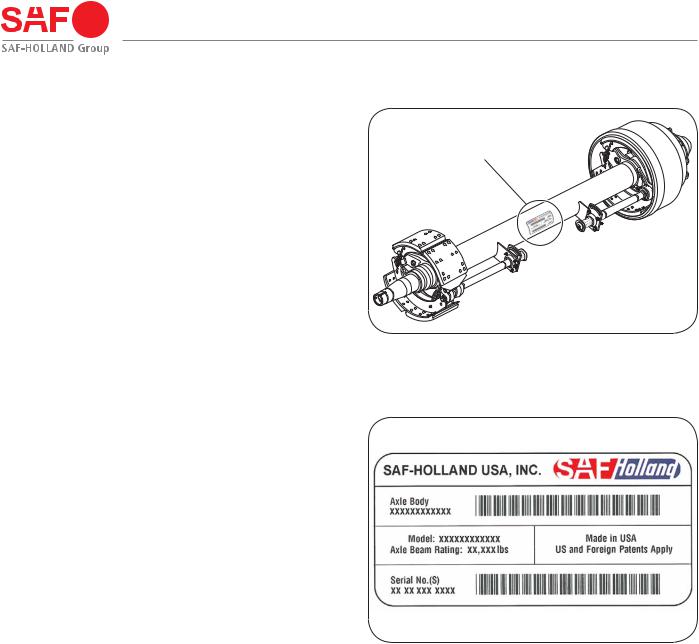
2. Model Identification |
Figure 1 |
The Drum Brake Axle Serial Tag is located near the center of |
SERIAL NUMBER TAG LOCATED |
the axle tube (Figure 1). |
|
|
NEAR CENTER OF AXLE TUBE |
3. Identification Tag
The sample tag shown will help you interpret the information |
Figure 2 |
on the SAF-HOLLAND USA Inc®. serial number tag. The model |
|
number, axle body part number, axle beam rating, and serial |
|
number are listed on the tag (Figure 2). |
|
Record your tag numbers below for future quick reference. |
|
AxleBodyPartNumber_________________________________ |
|
Model Number _______________________________________ |
|
AxleBeamRating_____________________________________ |
|
Serial Number _______________________________________ |
|
XL-TA10006OM-en-US Rev B · 2014-03-13 · Amendments and Errors Reserved · © SAF-HOLLAND, Inc., SAF-HOLLAND, HOLLAND, SAF, |
5 |
and logos are trademarks of SAF-HOLLAND S.A., SAF-HOLLAND GmbH, and SAF-HOLLAND, Inc. |
|
|
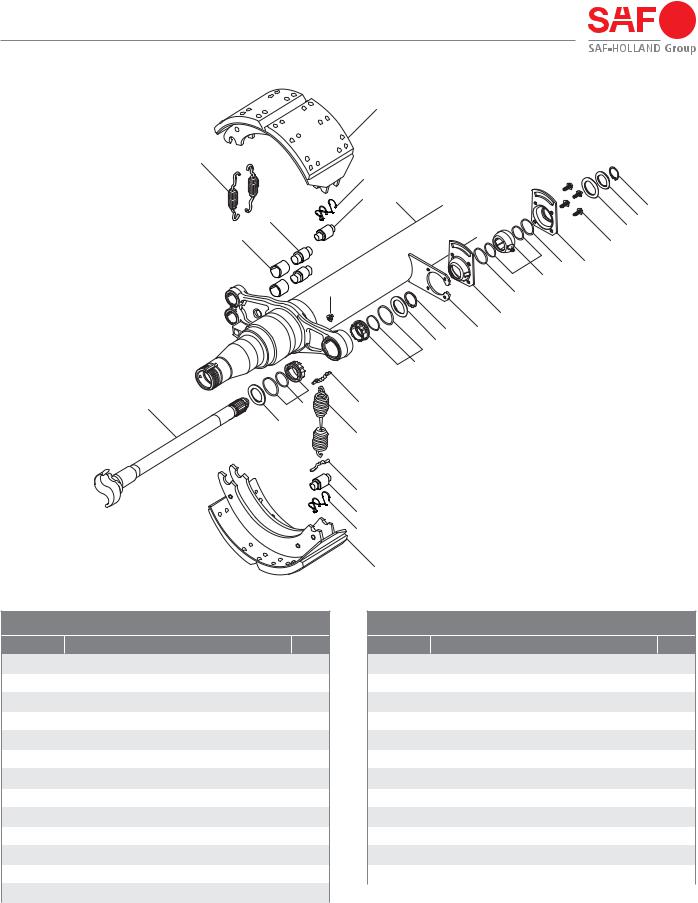
Brake Components Parts List – Prior to November 30, 2012
5
16
8 |
|
|
|
9 |
1 |
|
25 |
|
|
|
|
4 |
|
|
23 |
|
|
24 |
|
3 |
|
|
22 |
|
|
20 |
21 |
|
|
19 |
|
2 |
|
20 |
|
|
|
17 LH AND 18 RH (NOT SHOWN) |
|
|
13 |
AXLE |
|
|
12 |
BRACKET |
|
|
6 |
|
|
10 LH AND |
7 |
14 |
11 RH (NOT SHOWN) |
||
|
12 |
|
15
14
9
8
5
TAPERED SPINDLE AXLE SHOWN
BRAKE COMPONENTS
ITEM |
DESCRIPTION |
QTY |
1 |
Axle Body Assembly |
1 |
|
|
|
2 |
Fitting, Lubrication |
2 |
|
|
|
3 |
Bushing, Anchor Pin |
4 |
|
|
|
4 |
Pin, Anchor |
4 |
|
|
|
5 |
Brake Shoe Assembly |
4 |
|
|
|
6 |
Bearing Assembly, S-Cam-Spider inboard |
2 |
|
|
|
7 |
Bearing Assembly, S-Cam-Spider Outboard |
2 |
|
|
|
8 |
Retainer, Roller |
4 |
|
|
|
9 |
Roller, Brake Shoe |
4 |
|
|
|
10 |
S-Camshaft, Left-Hand |
1 |
|
|
|
11 |
S-Camshaft, Right-Hand (not shown) |
1 |
|
|
|
12 |
Washer, S-Cam Bearing-Outboard |
4 |
|
|
|
13 |
Retainer Ring |
2 |
|
|
|
BRAKE COMPONENTS
ITEM |
|
DESCRIPTION |
QTY |
14 |
|
Return Spring Pin |
4 |
|
|
|
|
15 |
|
Spring, Return-Hub/Drum |
2 |
|
|
|
|
16 |
|
Spring, Anchor Pin |
4 |
|
|
|
|
17 |
|
Housing, S-Cam Bearing, Left-Hand Slotted |
1 |
|
|
|
|
18 |
|
Housing, S-Cam Bearing, Right-Hand Slotted |
1 |
|
|
|
|
19 |
|
Bearing Assembly S-Camshaft |
2 |
|
|
|
|
20 |
|
O-Ring, S-Camshaft Bearing Seal-Inboard |
4 |
|
|
|
|
21 |
|
Housing, S-Cam Bearing |
2 |
|
|
|
|
22 |
|
Screw, Thread Rolling Tapping |
8 |
|
|
|
|
23 |
|
Washer, Shaft End |
2 |
|
|
|
|
24 |
|
Washer, Shaft End |
2 |
|
|
|
|
25 |
|
Retaining Ring |
2 |
|
|
|
|
|
|
|
|
NOTE: |
Refer to Drum Brake Axle Parts Manual XL-TA10058PM-en-US for |
||
|
axle component and service kit part numbers. |
|
|
|
|
|
|
6 |
XL-TA10006OM-en-US Rev B · 2014-03-13 · Amendments and Errors Reserved · © SAF-HOLLAND, Inc., SAF-HOLLAND, HOLLAND, SAF, |
|
and logos are trademarks of SAF-HOLLAND S.A., SAF-HOLLAND GmbH, and SAF-HOLLAND, Inc. |
|

Brake Components Parts List – After November 30, 2012
 5
5
16
8
4 9
3
2
 13
13
12
7
6
10 LH AND |
7 |
24 |
11 RH (NOT SHOWN)
14
15
 9
9
8
5
1
23
21
22
22 20
17 LH & 18 RH (NOT SHOWN) AXLE
19 BRACKET
TAPERED SPINDLE AXLE SHOWN
BRAKE COMPONENTS
ITEM |
DESCRIPTION |
QTY |
1 |
Axle Body Assembly |
1 |
|
|
|
2 |
Fitting, Lubrication |
2 |
|
|
|
3 |
Bushing, Anchor Pin |
4 |
|
|
|
4 |
Pin, Anchor |
4 |
|
|
|
5 |
Brake Shoe Assembly |
4 |
|
|
|
6 |
Bushing, Cam Bearing |
2 |
|
|
|
7 |
Cam Seal, Spider |
4 |
|
|
|
8 |
Retainer, Cam Roller |
4 |
|
|
|
9 |
Roller, Brake Shoe |
4 |
|
|
|
10 |
S-Camshaft, Left-Hand |
1 |
|
|
|
11 |
S-Camshaft, Right-Hand (not shown) |
1 |
|
|
|
12 |
Washer, S-Cam Bearing-Outboard |
2 |
|
|
|
BRAKE COMPONENTS
ITEM |
|
DESCRIPTION |
QTY |
13 |
|
Retainer Ring |
2 |
|
|
|
|
14 |
|
Return Spring Pin |
4 |
|
|
|
|
15 |
|
Spring, Return-Hub/Drum |
2 |
|
|
|
|
16 |
|
Spring, Anchor Pin |
4 |
|
|
|
|
17 |
|
Cam Bearing Kit - Left-Hand |
1 |
|
|
|
|
18 |
|
Cam Bearing Kit - Right-Hand (not shown) |
1 |
|
|
|
|
19 |
|
Nut, Lock |
8 |
|
|
|
|
20 |
|
Bolt, Hex Head Cap |
8 |
|
|
|
|
21 |
|
Washer, Shaft End |
2 |
|
|
|
|
22 |
|
Washer, Shaft End |
4 |
|
|
|
|
23 |
|
Retaining Ring |
2 |
|
|
|
|
24 |
|
Guide PLate, Brake Roller Shoe |
2 |
|
|
|
|
|
|
|
|
NOTE: |
Refer to Drum Brake Axle Parts Manual XL-TA10058PM-en-US for |
||
|
axle component and service kit part numbers. |
|
|
|
|
|
|
XL-TA10006OM-en-US Rev B · 2014-03-13 · Amendments and Errors Reserved · © SAF-HOLLAND, Inc., SAF-HOLLAND, HOLLAND, SAF, |
7 |
and logos are trademarks of SAF-HOLLAND S.A., SAF-HOLLAND GmbH, and SAF-HOLLAND, Inc. |
|
|

Hubs, Bearings, and Seal Components
4. Hubs, Bearings and Seal Removal |
Figure 3 |
NOTE: Before you begin any axle/brake service procedures, |
|
park the vehicle on a level surface. Block the wheels |
|
to prevent the vehicle from moving. Support the |
|
vehicle and axle(s) with safety stands. DO NOT work |
|
under a vehicle supported only by jacks. Jacks can |
|
slip or fall over. Serious personal injury and damage |
|
to components can result. |
|
Failure to properly support the vehicle and |
|
axles prior to commencing work could |
|
create a crush hazard which, if not avoided, |
|
could result in death or serious injury. |
|
1. Release trailer brakes and cage spring brakes according |
|
to spring brake manufacturer’s instructions. Remove tire |
|
and wheel assembly to access hub and drum. |
|
2. Remove drum from hub using support device such as a |
|
drum dolly (Figure 3). |
Figure 4 |
Failure to support weight during installation |
|
or removal of brake drum could create a |
|
crush hazard which, if not avoided, could |
|
result in minor to moderate injury. |
|
NOTE: It is necessary to retract brake shoes in accordance with brake adjuster’s manufacturer manual to allow brake drum to clear brake shoes during brake drum removal.
HUB CAP
GASKET
HUB CAP
BOLTS (6)
3. Remove the hub cap and gasket by removing six (6) bolts (Figure 4).
NOTE: Be prepared to collect lubrication fluid when removing the hub cap.
8 |
XL-TA10006OM-en-US Rev B · 2014-03-13 · Amendments and Errors Reserved · © SAF-HOLLAND, Inc., SAF-HOLLAND, HOLLAND, SAF, |
|
and logos are trademarks of SAF-HOLLAND S.A., SAF-HOLLAND GmbH, and SAF-HOLLAND, Inc. |
|

Hubs, Bearings, and Seal Components
4.Remove set screws (Figure 5).
5.Remove the axle nut from the spindle using a wrench with the axle nut socket. If the unit is equipped with a Pro-Torq® spindle nut, remove nut and skip Step 5.
(Figure 6).
6.Release the axle washer and inner axle nut from the spindle (Figure 6).
7.Remove the outer hub bearing from the spindle (Figure 6).
NOTE: With axle nut, washer, and inner nut removed, it is possible to access the outer bearing.
DO NOT hit steel parts with a steel hammer as parts could break, sending flying steel fragments in any direction creating a hazard which, if not avoided, could result in minor to moderate injury.
8.Grasp the hub assembly with both hands and pull the hub assembly off the axle spindle (Figure 7).
NOTE: Depending on the type of hub seal, the hub seal and inner bearing could remain on spindle or come off with hub assembly.
Figure 5
OUTER HUB BEARING
INNER AXLE NUT
AXLE WASHER
SET SCREWS
AXLE NUT
3-PIECE SPINDLE NUT SHOWN
Figure 6
PRO-TORQ®
 SPINDLE NUT
AXLE NUT
SOCKET
Figure 7
HUB ASSEMBLY
XL-TA10006OM-en-US Rev B · 2014-03-13 · Amendments and Errors Reserved · © SAF-HOLLAND, Inc., SAF-HOLLAND, HOLLAND, SAF, |
9 |
and logos are trademarks of SAF-HOLLAND S.A., SAF-HOLLAND GmbH, and SAF-HOLLAND, Inc. |
|
|

Hubs, Bearings, and Seal Components
9.Remove the inner hub bearing from the spindle or from the inside of the hub (Figure 8).
10.Remove the hub seal from the hub bore using a pry bar. A spindle mount hub seal can be driven off the spindle by striking the ring from the back side or prying off with a crow’s foot bar. Discard the used hub seal and use a new hub seal during re-assembly being careful not to gouge the spindle shoulder (Figure 8).
DO NOT use a chisel to cut the seal. The shoulder can be damaged, resulting in a leak which could lead to wheel end and/or brake failure.
5. Bearing Inspection
Figure 8
HUB SEAL
INNER HUB BEARING
Thoroughly clean bearings. DO NOT mix a synthetic base grease or oil with an organic/mineral base lubricant.
DO NOT spin dry hub bearings with compressed air. Bearing damage could result.
1.After removing the hub assembly, clean excess grease from the bearings.
IMPORTANT: A bearing which has been removed from a vehicle should be cleaned with solvent.
When cleaning DO NOT use steam or water which will cause bearings to rust.
IMPORTANT: Bearings that are rusted, flaked, pitted, or have damaged cages should be replaced. It is recommended to replace all questionable bearings and ALWAYS replace the cup and cone as a matched set. NEVER re-assemble a tapered roller bearing in a damaged or worn housing or on damaged or worn spindles. Housings or spindles should
be replaced and NOT re-machined if the bearing journal is worn.
10 |
XL-TA10006OM-en-US Rev B · 2014-03-13 · Amendments and Errors Reserved · © SAF-HOLLAND, Inc., SAF-HOLLAND, HOLLAND, SAF, |
|
and logos are trademarks of SAF-HOLLAND S.A., SAF-HOLLAND GmbH, and SAF-HOLLAND, Inc. |
|
 Loading...