


Owner’s Manual
Manual del propietario
Mode d’emploi
FW35 Series Fifth Wheel
Operation, Maintenance and Troubleshooting
Procedures; Warranty Information
Quinta rueda Serie FW35
Operación, mantenimiento y procedimientos de resolución de problemas; Información de garantía
Sellette d’attelage Série FW35
Procédures d’utilisation, d’entretien et de dépannage; informations sur la garantie
Français Español English
XL-FW10009UM-en-US Rev B

Contents
Contents |
|
Page |
Introduction.............................................. |
2 |
|
Notes, Cautions, and Warnings .................. |
2 |
|
Section 1 – Model Identification................ |
3 |
|
Section 2 – Decal Requirements ................ |
3 |
|
Section 3 – General Safety Instructions |
.....4 |
|
Section 4 – Fifth Wheel Intended Use ........ |
5 |
|
Section 5 – Fifth Wheel Non-Intended Use...5 |
||
Section 6 – Coupling Preparation .............. |
5 |
|
Section 7 |
– Coupling Procedures ............... |
6 |
Section 8 |
– Uncoupling Procedures ........... |
9 |
Section 9 |
– Positioning Sliding Fifth Wheel |
...11 |
Introduction
This manual provides the information necessary for the proper operation and maintenance of Holland 35 series fifth wheels.
NOTE: For Holland replacement components contact SAF-HOLLAND Customer Service at 888-396-6501.
Notes, Cautions, and Warnings
You must read and understand all of the procedures presented in this manual before operating or starting work on any Holland 35 Series fifth wheel.
IMPORTANT: Keep this manual in a safe location for future reference.
Proper tools must be used to perform the maintenance and repair procedures described in this manual.
NOTE: In the United States, workshop safety requirements are defined by federal and/or state Occupational Safety and Health Acts. Equivalent laws may exist in other countries. This manual is written based on the assumption that OSHA or other applicable employee safety regulations are followed by the location where work is performed.
Contents |
|
Page |
Section 10 – Fifth Wheel Maintenance |
....12 |
|
Section 11 – Top Plate Removal .............. |
13 |
|
Section 12 – Fifth Wheel Lubrication ....... |
14 |
|
Section 13 – Slide Base Lubrication.......... |
16 |
|
Section 14 – Fifth Wheel Adjustment ....... |
16 |
|
Section 15 – Slide Base Adjustment......... |
18 |
|
Section 16 – Pocket Insert Inspection ...... |
19 |
|
Section 17 |
– Top Plate Installation........... |
20 |
Section 18 |
– Troubleshooting .................. |
21 |
Section 19 |
– Rebuild and Replacement Kits..23 |
|
Warranty and Performance Guarantee..... |
24 |
|
Throughout this manual, you will notice the terms “NOTE,” “IMPORTANT,” “CAUTION,” and “WARNING” followed by useful product information. So that you may better understand the manual, those terms are defined as follows:
NOTE: Includes additional information to enable accurate and easy performance of procedures.
IMPORTANT: Includes additional information that if not followed could lead to hindered product performance.
Used without the safety alert symbol, indicates a potentially hazardous situation which, if not avoided, could result in property damage.
Indicates a potentially hazardous situation which, if not avoided, could result in minor or moderate injury.
Indicates a potentially hazardous situation which, if not avoided, could result in death or serious injury.
2 |
XL-FW10009UM-en-US Rev B · 2012-06-05 · Amendments and errors reserved. © SAF-HOLLAND, Inc. |
|
|
Model Identification
1. Model Identification |
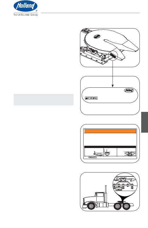
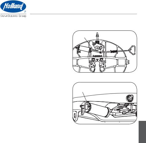
Figure 1 |
Fifth wheel serial tags are located on the left side of the fifth wheel top plate above the fifth wheel bracket pin, or on the pickup ramps (Figure 1).
The part number and serial number are listed on the tag (Figure 2).
2. Decal Requirements
Decal XL-FW350 (Figure 3) enclosed in the plastic bag with the Owner’s Manual, MUST be installed near the fifth wheel and easily viewed by the operator. Place the decal on a flat surface such as the frame rail or on the back of the cab (Figure 4).
NOTE: Make sure surface is free of oil and grease before applying decal.
It is the responsibility of the end user to periodically inspect the decal and ensure that it is clean and completely legible. If the label is missing, loose, damaged or difficult to read, contact SAF-HOLLAND Customer Service at 888-396-6501 to order replacements immediately.
Figure 2
U.S. AND FOREIGN PATENTS APPLY
Model No. XXXXXXXXXXXXXXXXXX
Serial No. XXXXXXXXXXXXXXXXXX |
MADE IN |
XXXXXX |
FAILURE TO PROPERLY INSTALL, MAINTAIN & OPERATE
THIS PRODUCT COULD RESULT IN TRACTOR TRAILER
SEPARATION CAUSING SERIOUS INJURY OR DEATH.
Figure 3

 WARNING / ADVERTENCIA / AVERTISSEMENT
ALWAYS inspect fifth wheel |
SIEMPRE inspeccione la quinta |
TOUJOURS contrôler la sellette |
after coupling tractor to trailer. |
rueda después de acoplar el |
d’attelage après avoir accouplé |
Failure to properly couple the |
tractocamión al remolque. |
le tracteur à la remorque. |
tractor and trailer could result in |
Si no acopla adecuadamente el |
Un mauvais accouplement de la |
tractor-trailer separation while in |
tractocamión y el remolque, podría |
remorque sur le tracteur peut résulter |
use which, if not avoided, could |
ocasionar la separación del |
en une séparation du tracteur et de la |
result in death or serious injury. |
tractocamión y el remolque durante |
remorque susceptible de provoquer |
|
el uso, lo cual, si no se evita, podría |
la mort ou des blessures graves. |
|
causar muertes o lesiones graves. |
|
CORRECT COUPLING / ACOPLAMIENTO CORRECTO / ACCOUPLEMENT CORRECT
1. Nut and washer snug against fifth wheel. |
2. No gap |
3. Locks completely closed around kingpin. |
Tuerca y arandela ajustadas contra la |
Sin separación |
Seguros completamente cerrados alrededor |
quinta rueda. |
Pas d’espacement |
del perno rey. |
Écrou et rondelle |
Mâchoires |
serrés contre |
complètement |
la sellette. |
fermées sur |
|
le pivot. |
Copyright © 2012 #SAF-HOLLAND, Inc. |
www.safholland.us |
English
Figure 4
XL-FW10009UM-en-US Rev B · 2012-06-05 · Amendments and errors reserved. © SAF-HOLLAND, Inc. |
3 |
|
|

General Safety Instructions
3. General Safety Instructions
Read and observe all Warning and Caution hazard alert messages in this manual. They provide information that can help prevent serious personal injury, damage to components, or both.
All fifth wheel installation and maintenance must be performed by a properly trained technician using proper tools and safe procedures.
IMPORTANT: Prior to operation of the fifth wheel, you must be thoroughly satisfied that the fifth wheel has been appropriately installed on the vehicle.
Failure to properly install the fifth wheel could result in tractor-trailer separation which, if not avoided, could result in death or serious injury.
For proper installation procedures, refer to SAF-HOLLAND Installation Manual XL-FW10008IM (available on the Internet at www.safholland.us).
Failure to follow all the operating procedures contained in these instructions could result in a hazardous condition or cause a hazardous condition to develop which, if not avoided, could result in death or serious injury.
These instructions apply to the proper operation of your fifth wheel only. There are other important checks, inspections, and procedures listed in the Owner’s Manuals for your tractor and trailer that are necessary, prudent, and/or required by law.
Only SAF-HOLLAND Original Parts should be used.
A list of SAF-HOLLAND technical support locations that supply SAF-HOLLAND Original Parts can be found on the Internet at www.safholland.us or contact our Customer Service at 888-396-6501.
Updates to this manual will be published as necessary on the Internet at www.safholland.us.
4 |
XL-FW10009UM-en-US Rev B · 2012-06-05 · Amendments and errors reserved. © SAF-HOLLAND, Inc. |
|
|

|
|
|
|
|
|
|
|
Operation Instructions |
|
|
|
|
|
|
|
||||
4. |
Fifth Wheel Intended Use |
2. |
Tow-away operations which damage |
||||||
|
|
|
|
|
|
|
|
or interfere with the proper operation |
|
1. |
Pulling trailers with standard SAE |
|
|
of the fifth wheel. |
|||||
|
|
kingpins which are in good condition |
3. |
|
The attachment of lifting devices. |
||||
|
|
and securely mounted or locked in |
|
||||||
|
|
4. |
The transport of loads in excess of |
||||||
|
|
position in the trailer. |
|||||||
2. |
Transporting loads that are within the |
|
|
rated capacity. |
|||||
5. |
Applications other than those |
||||||||
|
|
maximum fifth wheel rated capacities: |
|||||||
|
|
55,000 lbs. Maximum Vertical Load |
|
|
recommended in SAF-HOLLAND |
||||
|
|
150,000 lbs. Maximum Drawbar Pull. |
|
|
literature available on the Internet |
||||
3. |
|
In both on-road and off-road applications. |
|
|
at www.safholland.us. |
||||
|
|
|
|
||||||
|
6. |
Coupling Preparation |
|||||||
IMPORTANT: SAF-HOLLAND definition |
|
||||||||
|
|
|
of off-road refers to |
|
1. |
|
Prior to coupling, you MUST inspect |
||
|
|
|
terrain on which a |
|
|
||||
|
|
|
|
|
|
the fifth wheel and mounting. Perform |
|||
|
|
|
tractor-trailer operates |
|
|
|
|||
|
|
|
|
|
|
and verify the following: |
|||
|
|
|
which is unpaved and |
|
|
|
|||
|
|
|
|
|
|
|
|||
|
|
|
rough, or ungraded. Any |
|
|
|
t 5JHIUFO MPPTF GBTUFOFST |
||
|
|
|
terrain not considered |
|
|
|
t 3FQMBDF NJTTJOH GBTUFOFST |
||
|
|
|
part of the public |
|
|
|
|||
|
|
|
|
|
|
|
|||
|
|
|
highway system falls |
|
|
|
t 3FQBJS SFQMBDF NJTTJOH DSBDLFE PS |
||
|
|
|
under this heading. |
|
|
|
otherwise damaged components. |
||
4. |
|
As recommended in SAF-HOLLAND |
|
|
t $MFBO HSFBTF HSPPWFT JG B MBSHF |
||||
|
|
|
amount of debris is present. |
||||||
|
|
literature available on the Internet at |
|
|
|||||
|
|
|
|
|
|||||
|
|
www.safholland.us. |
|
|
t -VCSJDBUF GJGUI XIFFM UP USBJMFS |
||||
|
|
|
|
|
|
|
|
contact surfaces, if needed. |
|
5.Fifth Wheel Non-Intended Use
1.Operating with a non-SAE compliant kingpin, such as kingpins which are bent, improper size or dimensions, not secured to maintain SAE configuration, or which are installed in warped trailer bolster plates, or upper coupler and fifth wheel lube plates that do not maintain the SAE kingpin dimensions. Refer to SAF-HOLLAND Service Bulletin XL-SB004-01 (available on the Internet at www.safholland.us) for more information on fifth wheel lube plates.
Failure to couple with a SAE compliant kingpin could result in improper coupling, allowing tractor-trailer separation, which if not avoided, could result in death or serious injury.
t *OTQFDU GJGUI XIFFM NFDIBOJTN
Lubricate dry or rusty components.
t *G ZPV IBWF B TMJEJOH mGUI XIFFM NBLF sure both plungers are fully engaged.
t *OTQFDU BJS MJOF DPOOFDUJPOT
t .BLF TVSF mGUI XIFFM JT JO BQQSPQSJBUF position for weight distribution on the tractor. For proper positioning of the fifth wheel, refer to SAF-HOLLAND publication XL-FW10008IM available on the Internet at www.safholland.us.
2.Make sure coupling area is flat, level, and clear of persons and obstacles.
XL-FW10009UM-en-US Rev B · 2012-06-05 · Amendments and errors reserved. © SAF-HOLLAND, Inc. |
5 |
|
|
English
Operation Instructions
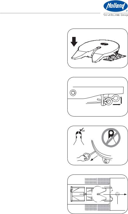
3.Tilt ramps of fifth wheel downward
(Figure 5).
4.Make sure locks are open. If locks are closed:
a.Manual Release: If equipped with a manual secondary lock, first pull secondary release handle and hook on casting (Figure 6). Pull the release handle completely out (Figure 7).
b.Air Release: Set the tractor parking brake and pull the fifth wheel release valve until locking mechanism opens and locks in place. Release the pull valve. Release the tractor parking brake.
5.Visually inspect fifth wheel throat to ensure locks are completely open and ready to accept kingpin (Figure 7).
6.If locks are not completely open (Figure 7), check the following:
a.Nut and washer at front of fifth wheel are not snug against the wheel.
b.Release handle is in extended “open” position.
If both of these conditions exist, you will still be able to couple the fifth wheel even though the lock jaws appear closed. The movement of the kingpin into the fifth wheel jaws will allow them to open and successfully couple.
If either above conditions do not exist, repeat Steps 4 - 6.
Figure 5
TILT DOWNWARD
Figure 6
Figure 7
LOCKS ARE
OPEN
7. |
Coupling Procedures |
|
|
|
|
1. |
Chock trailer wheels. |
Figure 8 |
|
||
2. |
Position the tractor so the center of the |
|
|
|
|
|
fifth wheel is aligned with the kingpin. |
|
|
|
|
|
|
|
|
|
|
3. |
Traveling in a straight line, slowly back |
|
|
|
|
|
|
|
|
||
|
|
|
|
||
|
tractor to trailer. STOP the tractor before |
|
|
|
|
|
|
|
|
|
|
|
making contact with the trailer |
|
|
|
|
|
|
|
|
|
|
|
(Figure 8). |
|
|
|
|
|
|
|
|
|
|
|
|
|
|
|
|
|
|
|
|
|
|
|
|
|
|
|
|
LOCKS ARE CLOSED
TRAILER (TOP)
KINGPIN
6 |
XL-FW10009UM-en-US Rev B · 2012-06-05 · Amendments and errors reserved. © SAF-HOLLAND, Inc. |
|
|
Operation Instructions
4.Set tractor parking brake and place into neutral.
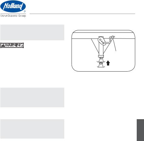
5.Completely exhaust air from tractor suspension, ensuring that the fifth wheel is below the contact surface of trailer (Figure 9).
6.Exit the cab and make sure the fifth wheel is below the upper coupler plate. Verify proper fifth wheel height. If trailer is too low, use landing gear to raise the trailer height.
NOTE: For proper operation of landing gear, follow the instructions published by the landing
gear manufacturer.
7.Slowly back up, using lowest gear possible. Stop when fifth wheel is under the leading edge of the trailer
(Figure 10).
8.Set tractor parking brake. Place in neutral. Exit cab and verify proper fifth wheel to kingpin alignment.
9.Adjust tractor suspension to ride height. The fifth wheel plate face MUST make contact with the upper coupler plate (Figure 11). If fifth wheel does not make contact with the upper coupler plate, use the landing gear to lower the trailer until fifth wheel makes contact.
IMPORTANT: If trailer is too high the kingpin will not properly connect with the lock jaw.
Failure to couple with the trailer at the proper height could result in improper coupling, allowing tractor and trailer separation, which if not avoided, could result in death or serious injury.
Figure 9
EXHAUST SUSPENSION AIR BEFORE BACKING UP
Figure 10
BACK UP
AND STOP!
Figure 11
XL-FW10009UM-en-US Rev B · 2012-06-05 · Amendments and errors reserved. © SAF-HOLLAND, Inc. |
7 |
|
|
English
Operation Instructions
IMPORTANT: Never inflate the tractor suspension when the kingpin is above the throat of the fifth wheel.
Failure to avoid inflating tractor suspension when the fifth wheel is not forward of the king pin, could result in damage to the kingpin and fifth wheel.
10.Slowly back into the trailer, engaging kingpin in the fifth wheel.
11.Connect the air and electrical lines.
12.Raise the landing gear legs until the pads are just above the ground.
13.Perform a pull test as an INITIAL CHECK by locking the trailer brakes and pulling forward with the tractor to make sure that tractor-trailer separation does not occur (Figure 12).
Figure 12
LOCK TRAILER BRAKES AND
PULL FORWARD WITH TRACTOR
Figure 13
NUT AND |
1/4" (6.35 mm) |
|
WASHER |
||
OR LESS GAP |
||
SNUG |
||
|
||
AGAINST |
NO GAP! |
|
FIFTH |
||
|
||
WHEEL |
|
|
|
LOCKS COMPLETELY |
|
|
CLOSED AROUND |
|
|
KINGPIN |
14.Set the tractor parking brake.
15.Exit the cab and visually inspect for the following to ensure that the lock is closed (Figure 13).
a.Nut and washer MUST be snug against the fifth wheel casting.
b.No gap is permissible between the trailer upper coupler plate and the fifth wheel.
c.Fifth wheel locks MUST be closed around the trailer kingpin with 1/4" (6.35 mm) or less gap visible between the lock jaws.
16.If you DO NOT achieve a proper couple, repeat the coupling procedure.
Failure to properly couple the tractor and trailer could result in tractor-trailer separation while in use which, if not avoided, could result in death or serious injury.
8 |
XL-FW10009UM-en-US Rev B · 2012-06-05 · Amendments and errors reserved. © SAF-HOLLAND, Inc. |
|
|
Operation Instructions
IMPORTANT: DO NOT use any fifth |
Figure 14 |
|
|
wheel that fails to |
|
operate properly. |
|
Failure to repair a |
|
malfunctioning fifth |
|
wheel before use could |
SECURE |
result in tractor-trailer |
CRANK |
separation which, if not |
|
avoided, could result in |
|
death or serious injury. |
|
17.Fully retract the landing gear legs off the ground and secure the crank handle (Figure 14).
NOTE: For proper operation of landing gear, follow the instructions published by the landing
gear manufacturer.
18.Remove the wheel chocks and continue with the pre-trip inspection.
NOTE: For no-tilt fifth wheels used with rigid upper couplers, always remove no-tilt shaft assembly for on-road use.
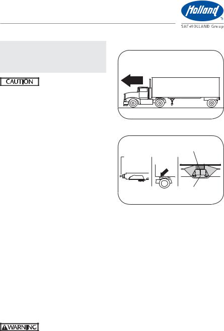
8. Uncoupling Procedures
1.Position the tractor and trailer, in straight alignment, on firm, level ground clear of obstacles and persons.
2.Set the trailer brakes.
3.Slowly back the tractor tightly against the trailer to relieve pressure on the fifth wheel locks.
4.Set the tractor parking brake.
XL-FW10009UM-en-US Rev B · 2012-06-05 · Amendments and errors reserved. © SAF-HOLLAND, Inc. |
9 |
|
|
English
Operation Instructions
IMPORTANT: DO NOT exhaust air from tractor suspension before uncoupling.
Failure to avoid exhausting tractor suspension before uncoupling could result in difficulty uncoupling tractor from trailer which, if not avoided, could result in damage to the fifth wheel and kingpin.
5.Chock the trailer wheels.
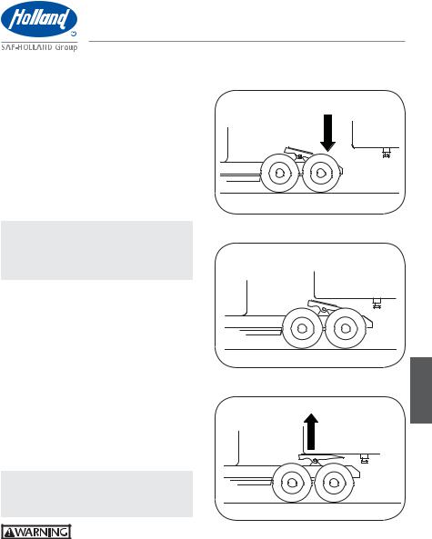
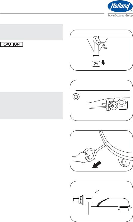
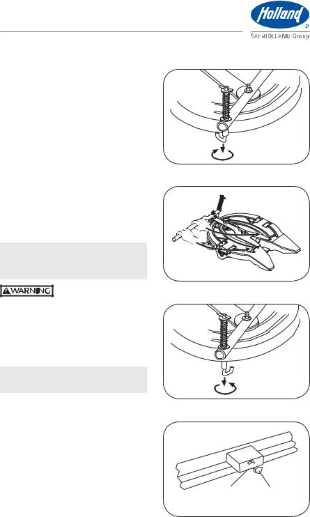
6.Lower the landing gear until the pads just touch the ground (Figure 15).
NOTE: For proper operation and ability to transfer trailer weight from the fifth wheel, follow the landing gear manufacturer’s published instructions. DO NOT raise trailer off of the fifth wheel.
7.Disconnect the air and electrical lines from the trailer and secure to tractor.
8.If equipped, pull the secondary lock release handle and hook on casting
(Figure 16).
9.Pull the release handle (Figure 17). If air release equipped, pull and hold the fifth wheel release valve until locking mechanism opens and locks in place.
10.Ensure locking mechanism is open and yoke shaft is in out position (Figure 18).
Figure 15
 LOWER LANDING GEAR
Figure 16
Figure 17
Figure 18
YOKE SHAFT
10 |
XL-FW10009UM-en-US Rev B · 2012-06-05 · Amendments and errors reserved. © SAF-HOLLAND, Inc. |
|
|
Operation Instructions
11.Release the tractor parking brake and slowly pull forward 12"-18" (306-457 mm) to disengage kingpin from fifth wheel. Fifth wheel should be between the front edge of trailer and kingpin (Figure 19).
IMPORTANT: DO NOT drive the tractor free of the trailer.
12.Set the tractor parking brake and place into neutral. Completely exhaust air from tractor suspension, ensuring that the fifth wheel is below the contact surface of trailer (Figure 20).
13.Visually inspect uncoupling. Make sure the trailer is completely supported by the landing gear.
14.Release the tractor parking brake and slowly pull away from the trailer.
15.Apply air to the tractor air suspension and allow suspension to return to ride height (Figure 21).
9.Positioning Sliding Fifth Wheels
1.Position the tractor and trailer, in straight alignment, on firm, level ground clear of obstacles and persons.
2.Set tractor and trailer parking brakes, place tractor in neutral.
Failure to stop and properly lock the tractor and trailer brakes could cause uncontrolled sliding of fifth wheel which, if not avoided, could result in component damage to tractor or trailer.
3.Release slide locking plungers by moving cab switch to unlock position (Figure 22). If manual slide release equipped, pull release lever. If plungers do not come out, lower the landing gear to relieve pressure on the fifth wheel. This will allow fifth wheel to slide easier.
NOTE: Cab switch style may differ by OEM.
Figure 19
SLOWLY PULL FORWARD
AND STOP
Figure 20
EXHAUST SUSPENSION AIR BEFORE PULLING FORWARD
Figure 21
RETURN TRACTOR SUSPENSION TO RIDE HEIGHT
Figure 22
AIR OPERATED
MOVE CAB SWITCH TO
UNLOCK POSITION
XL-FW10009UM-en-US Rev B · 2012-06-05 · Amendments and errors reserved. © SAF-HOLLAND, Inc. |
11 |
|
|
English

Maintenance Procedures
4.Visually inspect and verify that plungers are disengaged.
5.Release tractor parking brake while keeping trailer brakes engaged.
6.Slowly drive the tractor forward or backward to position fifth wheel. Stop tractor at desired position.
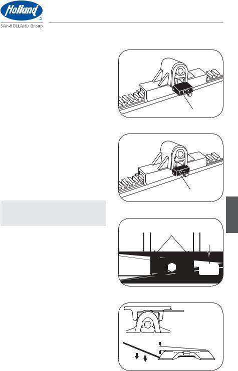
7.Re-engage slide locking plungers by moving cab switch to the lock position (Figure 23). If manual slide release equipped, pull release arm to allow plungers to retract.
8.Place tractor in neutral, set tractor parking brake.
9.Visually inspect plunger lock bars to ensure proper engagement (Figure 24).
10.Retract landing gear legs, if lowered.
11.Verify that slide locking plungers have been re-engaged by performing a pull test (Figure 25).
IMPORTANT: DO NOT operate the vehicle if the plungers are not fully engaged (locked).
Failure to properly engage plungers and slide base could cause loss of vehicle control which, if not avoided, could result in death or serious injury.
10. Fifth Wheel Maintenance
IMPORTANT: All maintenance MUST be performed by a properly trained technician using proper tools and safe procedures.
IMPORTANT: All maintenance must be performed while the tractor is uncoupled from the trailer.
Figure 23
AIR OPERATED
MOVE CAB SWITCH
TO LOCK POSITION
Figure 24
LOCKED (ENGAGED)
RACK
 PLUNGER
TRADITIONAL SLIDERS
Figure 25
LOCK TRAILER BRAKES AND
PULL FORWARD WITH TRACTOR
12 |
XL-FW10009UM-en-US Rev B · 2012-06-05 · Amendments and errors reserved. © SAF-HOLLAND, Inc. |
|
|
Maintenance Procedures
Failure to properly maintain your fifth wheel could result in tractor-trailer separation which, if not avoided, could result in death or serious injury.
NOTE: Removal of the fifth wheel top plate is not required for
maintenance but may be required when performing repairs.
11. Top Plate Removal
IMPORTANT: Fifth wheel assembly has replaceable pocket inserts installed between the fifth wheel top plate and mounting base. When removing top plate, be careful not
to lose pocket inserts.
Failure to prevent pocket inserts from falling out of the top plate could cause a potentially hazardous situation which, if not avoided, could result in minor or moderate injury.
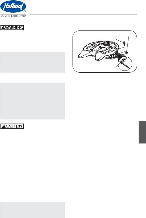
1.Remove bracket pin retention nuts and bolts from both sides of fifth wheel top plate (Figure 26).
2.Using a pry bar, pull bracket retention pins out of fifth wheel top plate
(Figure 26).
3.Using a lifting device capable of lifting 500 lbs. (227 kg), remove the top plate from the mounting base. Place fifth wheel on a flat, clean working area.
NOTE: Follow instructions published by lifting device manufacturer for proper operation of lifting device.
Figure 26
RETENTION NUT
RETENTION BOLT
TOP
PLATE
BRACKET PIN
XL-FW10009UM-en-US Rev B · 2012-06-05 · Amendments and errors reserved. © SAF-HOLLAND, Inc. |
13 |
|
|
English
Maintenance Procedures
12. Fifth Wheel Lubrication |
Figure 27 |
IMPORTANT: Fifth wheel lubrication |
GREASE THE TRAILER |
is necessary to get the |
CONTACT SURFACE |
maximum service life |
|
from your 35 series |
|
fifth wheel. Perform the |
|
following procedures at |
|
the intervals listed. |
|
t -VCSJDBUF MPDLJOH NFDIBOJTN FWFSZ UISFF
(3) months or 30,000 miles.
t 5IPSPVHIMZ DMFBO UIF MPDLJOH NFDIBOJTN every six (6) months or 60,000 miles.
IMPORTANT: If your fifth wheel operates in snowy or icy winter conditions, lubrication should be performed every spring in addition to
routine lubrication (as noted above) to ensure optimum operation.
12.A Proper Lubrication Method
Figure 28
C D |
E |
F |
|
B |
G |
A |
|
H
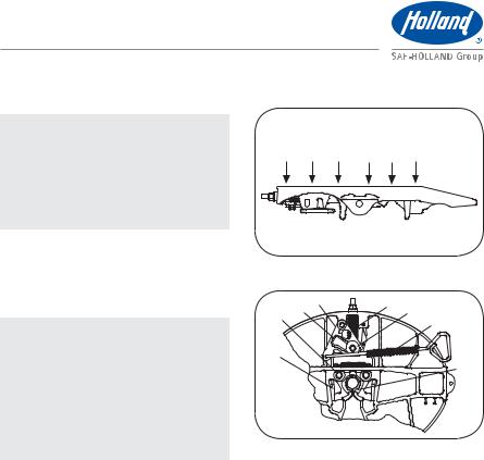
1.Remove old grease and debris from all fifth wheel-to-trailer contact surfaces. Apply new water-resistant lithium-based grease to all fifth wheel-to-trailer contact surfaces (Figure 27).
2.Using water-resistant lithium-based grease, lubricate (A) yoke tips where contact is made with the locks and casting, (C) cam profile, (E) yoke shaft in area that slides in and out of the fifth wheel casting, (F) secondary lock where contact is made with the cam plate, (G) release handle, and
(H) where contact is made with the kingpin (Figure 28).
3.Using a light oil, lubricate (D) cam pivot point (Figure 28).
4.Only if necessary, lubricate (B) lock pin with Never-Seez® (Figure 28).
14 |
XL-FW10009UM-en-US Rev B · 2012-06-05 · Amendments and errors reserved. © SAF-HOLLAND, Inc. |
|
|
Maintenance Procedures
If fifth wheel is air release equipped, follow Steps 5-9 for lubrication of the air cylinder.
5.Activate air cylinder control to extend piston and shaft to its full travel
(Figure 29).
6.Clean exposed piston shaft with penetrating oil and a clean shop towel. DO NOT use any abrasives on the exposed shaft as they could damage the piston shaft.
7.De-activate the air cylinder.
8.Remove supply air line and add 2 - 4 drops of air tool oil to cylinder through the supply fitting. Re-install supply air line (Figure 30).
9.Activate and de-activate air cylinder 2 - 3 times to work air tool oil into cylinder and onto piston and verify proper operation.
12.B As-Needed Lubrication
t .BJOUBJO MVCSJDBUJPO PO GJGUI wheel-to-trailer contact surfaces. Use a water-resistant lithium-based grease. Clean grease grooves if a large amount of debris is present
(Figure 27).
t $MFBO BOE MVCSJDBUF MPDLJOH NFDIBOJTN if operational difficulties arise during the service life of your fifth wheel (i.e. problems with coupling, uncoupling, or pulling the release handle (Figure 28).
Figure 29
PISTON SHAFT
Figure 30
SUPPLY FITTING
English
XL-FW10009UM-en-US Rev B · 2012-06-05 · Amendments and errors reserved. © SAF-HOLLAND, Inc. |
15 |
|
|

Maintenance Procedures
13. Slide Base Lubrication |
Figure 31 |
NOTE: Slide base should be moved fore |
|
and aft at least once a year to |
|
maintain optimum performance. |
PISTON |
|
SHAFT |
IMPORTANT: If equipped with air |
|
release, lubricate air |
|
cylinder every three (3) |
|
months or 30,000 miles |
|
whichever comes first. |
TRADITIONAL SLIDERS |
1. With the piston shaft in the exposed |
Figure 32 |
position, clean with penetrating oil |
|
and a clean shop towel (Figure 31). |
ILS SLIDER |
ILS Sliders: Spray spring covered piston |
|
shaft thoroughly with penetrating oil |
|
(Figure 32). |
|
IMPORTANT: DO NOT use any abrasives |
PISTON |
on the exposed shaft as |
SHAFT |
|
|
they could damage the |
|
piston shaft. |
|
2Remove supply air line and add 2-4 drops of air tool oil to cylinder through the supply fitting. Re-install supply air line
(Figures 33 and 34 - Traditional Sliders, Figure 35 - ILS Sliders).
3.Activate and de-activate air cylinder 2-3 times to work air tool oil into cylinder and onto piston and verify proper operation.
14. Fifth Wheel Adjustment
Fifth wheel adjustment should be performed at a minimum of every 60,000 miles or if excessive movement between kingpin and fifth wheel is noticed when driving the vehicle.
IMPORTANT: Excessive movement between the tractor and trailer can effect vehicle handling.
Figure 33
TRADITIONAL SLIDER
SUPPLY FITTING
Figure 34
SUPPLY FITTING
TRADITIONAL  SLIDER
16 |
XL-FW10009UM-en-US Rev B · 2012-06-05 · Amendments and errors reserved. © SAF-HOLLAND, Inc. |
|
|

Maintenance Procedures
Failure to maintain proper fifth wheel adjustment could result in loss of vehicle control which, if not avoided, could result in death or serious injury.
NOTE: To obtain proper adjustment SAF-HOLLAND recommends use of Holland lock tester Part No. TF-TLN-5001, available from your local Holland distributor.
1.Back off adjustment nut several turns
(Figure 38).
2.If fifth wheel is locked, pull release handle to unlock fifth wheel. If equipped with a manual secondary lock, first pull secondary release handle and hook on casting.
3.Set lock tester on fifth wheel top plate
(Figure 36).
4.To lock fifth wheel, rotate lock tester handle clockwise (Figure 37).
5.With locks closed around lock tester, position adjustment nut on yoke shaft so it is slightly compressing rubber washer making it difficult to turn by hand (Figure 38).
6.Turn adjustment nut one additional full turn clockwise to further compress rubber washer (Figure 38).
IMPORTANT: Over compressing the bushing with additional turns will take the fifth wheel out of proper adjustment and degrade the performance of the fifth wheel.
Figure 35
ILS SLIDER
SUPPLY
FITTING
Figure 36
 LOCK ADJUSTMENT TOOL
Figure 37
ROTATE HANDLE TO 
LOCK FIFTH WHEEL
Figure 38
ROTATE CLOCKWISE ONE
(1) ADDITIONAL TURN
RUBBER WASHER
ADJUSTMENT NUT
XL-FW10009UM-en-US Rev B · 2012-06-05 · Amendments and errors reserved. © SAF-HOLLAND, Inc. |
17 |
|
|
English
Maintenance Procedures
7.To unlock fifth wheel, push down and rotate “J” hook so it locks under front skirt of fifth wheel casting (Figure 39).
8.Pull release handle to unlock fifth wheel. If equipped with a manual secondary lock, first pull secondary release handle and hook on casting.
9.To unlock fifth wheel, grasp lock tester handle with both hands, and with a quick snap turn counter-clockwise (Figure 40).
10.Repeat coupling and uncoupling process with lock tester at least twice to help “seat” the yoke. Then re-check adjustment of the fifth wheel.
11.With fifth wheel unlocked, unhook “J” hook from under front skirt of fifth wheel casting (Figure 41) and remove lock tester from fifth wheel.
IMPORTANT: Before using your fifth wheel, you MUST verify that it is operating properly.
Failure to verify that fifth wheel is operating properly could result in tractor trailer separation which, if not avoided, could result in serious injury or death.
15. Slide Base Adjustment
NOTE: ILS slider locking plungers DO NOT require adjustment.
Some Holland slide bases are equipped with adjustable locking plungers. Adjustment should be performed at a minimum of every 60,000 miles or if excessive movement is noticed when driving the vehicle. To obtain proper adjustment, follow the following procedures:
1.Loosen lock nut and turn adjustment bolt counterclockwise (Figure 42).
Figure 39
Figure 40
Figure 41
Figure 42

 PLUNGER
LOCK NUT ADJUSTMENT BOLT
18 |
XL-FW10009UM-en-US Rev B · 2012-06-05 · Amendments and errors reserved. © SAF-HOLLAND, Inc. |
|
|
Maintenance Procedures
2.Disengage and engage locking plungers. Verify that locking plungers have engaged properly (Figures 43 and 44).
3.Tighten adjustment bolt until it contacts the rack.
4.Turn adjustment bolt clockwise an additional 1/2 turn, then tighten lock nut securely.
If locking plungers DO NOT release fully to allow fifth wheel to slide:
a.Check the air cylinder for proper operation. Replace if necessary.
b.Check locking plunger adjustment as explained above.
c.If a locking plunger is binding in the plunger pocket, remove the locking plunger using a Holland TF-TLN-2500 spring compressor. Grind the top edges of the locking plunger 1/16" (1.5 mm) (Figure 45). Re-install and adjust the locking plungers as explained above.
NOTE: If problems persists, contact SAF-HOLLAND Customer Service: 888-396-6501.
16. Pocket Insert Inspection
Replace pocket inserts if:
t 5IF QPDLFU JOTFSU UIJDLOFTT JT
(1.5 mm) or less.
t 5IF GSFF WFSUJDBM NPWFNFOU PG UPQ QMBUF on the bracket is 1/2" (12.7 mm) or greater, without compressing rubber bushings (Figure 46).
t 5IF QPDLFU JOTFSUT BSF TFWFSFMZ chipped, cracked or gouged.
Figure 43
UNLOCKED (RELEASED)
RACK
PLUNGER
Figure 44
LOCKED (ENGAGED)
RACK
PLUNGER
Figure 45
CHECK FOR POSSIBLE INTERFERENCE
1/16" (1.5 mm)
Figure 46
REPLACE IF 1/16" (1.5 mm) OR LESS
1/2" (12.7 mm) MAX. (MEASURED AT EAR)
English
PUSH DOWN
XL-FW10009UM-en-US Rev B · 2012-06-05 · Amendments and errors reserved. © SAF-HOLLAND, Inc. |
19 |
|
|
Maintenance Procedures
17. Top Plate Installation |
Figure 47 |
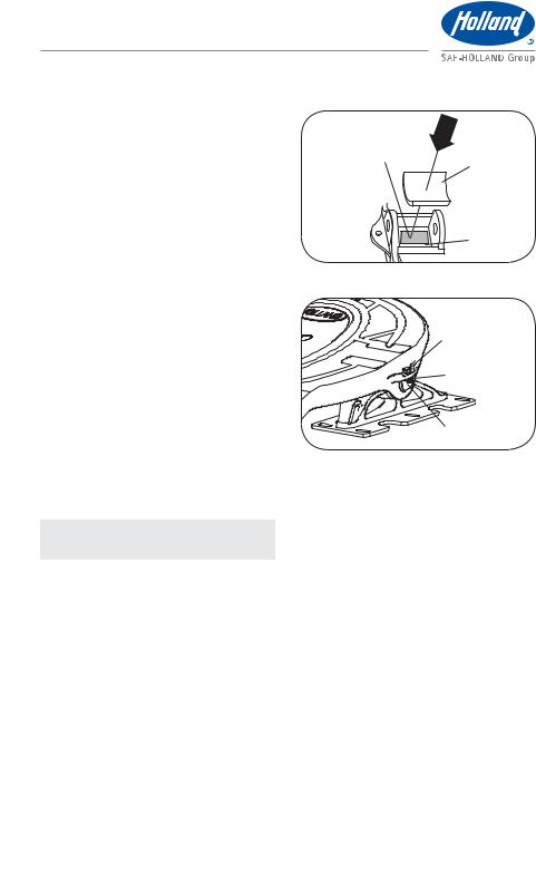
1.If pocket inserts are dislodged from fifth wheel casting, clean pocket area of
casting and apply a strip of double-face |
DOUBLE-FACE TAPE |
|
tape in bottom of pockets. Install pocket |
|
INSERT |
inserts by pressing down into pockets |
|
|
(Figure 47). |
|
|
2. Using a lifting device capable of lifting |
|
|
500 lbs. (227 kg), install the fifth wheel |
|
|
|
AREA |
|
top plate onto its mounting base. |
|
|
|
|
|
3. Install bracket pins through fifth wheel |
Figure 48 |
|
casting and mounting base and secure |
|
|
|
|
|
by installing the bracket pin retention |
|
TOP PLATE |
bolts and nuts (Figure 48). Torque |
|
|
|
|
|
retention fasteners to 50-60 ft.-lbs. |
|
RETENTION BOLT |
/tN |
|
|
|
|
|
4. No-Tilt Fifth Wheels: |
|
RETENTION NUT |
After installing top plate on mounting |
|
|
|
|
|
base, re-install no-tilt shaft assembly |
|
|
by orienting top plate so top plate and |
|
|
mounting base no-tilt brackets are |
|
BRACKET PIN |
aligned. Insert no-tilt shaft assembly |
|
|
from left side of fifth wheel, making |
|
|
sure chain assembly is positioned on |
|
|
outside of right-hand bracket. Attach |
|
|
chain assembly to bracket. |
|
|
NOTE: Always remove no-tilt shaft |
|
|
assembly for on-road use. |
|
|
20 |
XL-FW10009UM-en-US Rev B · 2012-06-05 · Amendments and errors reserved. © SAF-HOLLAND, Inc. |
|
|
|
|
|
|
|
Troubleshooting |
||
|
|
|
|
|
|
|
|
18. Troubleshooting |
|
|
|
|
|||
Difficult to Couple to Trailer: |
|
|
|
|
|||
|
|
|
|
|
|||
9 |
POSSIBLE CAUSE |
|
REMEDY |
|
|||
|
Attempting to couple too fast. |
|
Couple in accordance with the procedure in Section 7. |
|
|||
|
|
|
|||||
|
|
|
|
|
|||
|
The trailer may be too high; the kingpin |
|
Lower the trailer in accordance with manufacturer's |
|
|||
|
is not entering the locks properly. |
|
instructions. |
|
|||
|
|
|
|
||||
|
Locks are closed. |
|
If equipped with manual secondary lock, pull secondary |
||||
|
|
|
|
|
release handle and hook on casting. Pull release handle |
||
|
|
|
|
|
all the way out. If air release equipped, set tractor brakes |
||
|
|
|
|
|
and actuate fifth wheel control valve to open locks. |
|
|
|
|
|
|
|
Locks may be open even if they still appear closed. Check |
||
|
|
|
|
|
to make sure nut and washer at front of fifth wheel are not |
||
|
|
|
|
|
snug against fifth wheel and that release handle is in extended |
||
|
|
|
|
|
“open” position. If both of these conditions exist, you will still |
||
|
|
|
|
|
be able to couple fifth wheel. Movement of kingpin into fifth |
||
|
|
|
|
|
wheel jaws will allow them to open and successfully couple. |
||
|
|
|
|
|
|||
|
Accumulated rust or grime interfering with |
|
Thoroughly clean the fifth wheel and re-lubricate in |
|
|||
|
the lock operation. |
|
accordance with the procedure in Section 12. |
|
|||
|
|
|
|
||||
|
The locks are adjusted too tightly. |
|
Check lock adjustments in accordance with the procedure |
||||
|
|
|
|
|
in Section 14. |
|
|
|
|
|
|
|
|||
|
The locks may be damaged. |
|
The fifth wheel MUST be rebuilt using the appropriate |
|
|||
|
|
|
|
|
service kit. |
|
|
|
|
|
|
|
|||
|
Damaged, bent release handle. |
|
Replace release handle using the appropriate service kit. |
|
|||
|
|
|
|
|
|||
|
Damaged, bent yoke shaft from |
|
The fifth wheel MUST be rebuilt using the appropriate |
|
|||
|
improper coupling. |
|
service kit. |
|
|||
|
|
|
|
|
|||
|
Bent kingpin, damaged upper coupler, |
|
Check the kingpin and upper coupler plate as detailed |
|
|||
|
or improper use of “lube plate” may be |
|
in Holland Service Bulletin XL-SB020. Repair/replace as |
||||
|
interfering with lock movement. |
|
required. Remove any improperly installed or improperly |
||||
|
|
|
|
|
specified lube plates. Refer to Holland Service Bulletin |
|
|
|
|
|
|
|
XL-SB004-01 for lube plate warnings. |
|
|
|
|
|
|
|
|
||
Difficult to Uncouple from Trailer: |
|
|
|
|
|||
|
|
|
|
|
|||
9 |
POSSIBLE CAUSE |
|
REMEDY |
|
|||
|
|
|
|
|
|||
|
The tractor may be putting pressure |
|
Lock the trailer brakes and back the tractor tightly |
|
|||
|
against locks. |
|
against the kingpin to relieve the pressure on the fifth |
|
|||
|
|
|
|
|
wheel lock, set the brakes, then pull the release handle. |
|
|
|
Tractor too low. |
|
Raise tractor suspension to proper ride height. |
|
|||
|
|
|
|
|
|||
|
The secondary lock is not released. |
|
If manual secondary: pull release handle out and up |
|
|||
|
|
|
|
|
and lock open by hooking the handle on the top plate |
|
|
|
|
|
|
|
casting. If automatic secondary: inspect for missing or |
||
|
|
|
|
|
broken parts and repair or replace as required using the |
||
|
|
|
|
|
appropriate service kit. |
|
|
|
Accumulated rust or grime interfering with |
|
Thoroughly clean the fifth wheel and re-lubricate in |
|
|||
|
the lock operation. |
|
accordance with the procedure in Section 12. |
|
|||
|
The locks are adjusted too tightly. |
|
Check lock adjustments in accordance with the procedure |
||||
|
|
|
|
|
in Section 14. |
|
|
|
|
|
|
|
|
|
|
XL-FW10009UM-en-US Rev B · 2012-06-05 · Amendments and errors reserved. © SAF-HOLLAND, Inc. |
|
21 |
|||||
|
|
|
|
|
|
|
|
English

Troubleshooting
Difficult to Uncouple from Trailer (continued):
9 |
POSSIBLE CAUSE |
REMEDY |
|
|
|
|
The release handle will not stay out or must |
Replace the cam and release handle spring using the |
|
be held out when unlocking. |
appropriate service kits. |
|
|
|
|
Missing or damaged release system parts. |
The fifth wheel MUST be rebuilt using the appropriate service kit. |
|
|
|
|
Casting bent/damaged at throat area, |
The entire fifth wheel top plate MUST be replaced. |
|
restricting movement. |
|
|
Bent kingpin, damaged upper coupler, |
Check the kingpin and upper coupler plate as detailed |
|
or improper use of “lube plate” may be |
in Holland Service Bulletin XL-SB020. Repair/replace as |
|
interfering with lock movement. |
required. Remove any improperly installed or improperly |
|
|
specified lube plates. Refer to Holland Service Bulletin |
|
|
XL-SB004-01 for lube plate warnings. |
Excessive Movement between Fifth Wheel and Kingpin:
9 |
POSSIBLE CAUSE |
REMEDY |
|
|
|
|
Fifth wheel lock requires adjustment. |
Follow the procedures contained in Section 14. |
|
|
|
|
Fifth wheel cannot be adjusted further. |
The fifth wheel MUST be rebuilt using the appropriate service kit. |
|
|
|
|
Kingpin is loose. |
Repair trailer. |
|
|
|
|
Kingpin is worn. |
Check kingpin for acceptable wear with Holland TF-0110. |
|
|
Replace kingpin, if necessary. |
Lock Pins Raising: |
|
|
|
|
|
9 |
POSSIBLE CAUSE |
REMEDY |
|
|
|
|
Kingpin too short or improperly installed |
Check the kingpin and upper coupler plate as detailed in |
|
“lube plates.” |
Holland Service Bulletin XL-SB020. Repair/replace as required. |
|
|
Remove any improperly installed or improperly specified |
|
|
lube plates. Refer to Holland Service Bulletin XL-SB004-01 |
|
|
for lube plate warnings. Check if there is evidence on bottom |
|
|
of locks of kingpin making contact and “lifting” the locks. |
|
Locks are too tight around kingpin. |
Check lock adjustment in accordance with the procedure |
|
|
in Section 14. |
|
|
|
|
Kingpin is worn. |
Check kingpin for acceptable wear with the Holland part |
|
|
TF-0110. Replace the kingpin if necessary. |
|
|
|
|
Kingpin/Locks not lubricated |
Re-lubricate in accordance with the procedures in |
|
well enough. |
Section 12. |
|
Lock pins not lubricated well enough. |
Lubricate lock pins with Never-Seez®. |
|
If issues persist: |
Order grease-able lock pin repair kit with retaining rings |
|
|
and shims, RK-07292-82. |
Hard Steering or Binding: |
|
|
|
|
|
9 |
POSSIBLE CAUSE |
REMEDY |
|
|
|
|
Lack of lubrication on fifth wheel |
Lubricate top of fifth wheel plate using a high pressure, |
|
top surface. |
lithium-based grease. Follow recommended lubrication |
|
|
schedule as described in Section 12. |
|
Warped trailer upper coupler plate. |
Check upper coupler plate for flatness and replace, if |
|
|
necessary. Refer to Holland Service Bulletin XL-SB020. |
|
|
|
22 |
XL-FW10009UM-en-US Rev B · 2012-06-05 · Amendments and errors reserved. © SAF-HOLLAND, Inc. |
|
|
|
|
Rebuild and Replacement Kits
19. Rebuild and Replacement Kits
REBUILD AND REPLACEMENT KITS |
|
PART NUMBER |
Rebuild Kit-Standard Left Hand Release |
|
RK-351-A-L |
|
||
|
|
|
Rebuild Kit-Standard Right Hand Release |
|
RK-351-A |
|
|
|
Rebuild Kit-Left Hand Release with Manual Secondary Lock |
|
RK-351-A-02-L |
|
|
|
Rebuild Kit-Right Hand Release with Manual Secondary Lock |
|
RK-351-02-A |
|
|
|
Rebuild Kit-Air Release |
|
RK-351-80-A-L |
|
|
|
Lock Replacement Kit |
|
RK-351-07296 |
|
|
|
Lock Yoke Replacement Kit |
|
RK-351-07295 |
|
|
|
Cam Plate Pivot Bolt Hardware Replacement Kit |
|
RK-351-2083 |
|
|
|
Cam Plate Roller Bolt Hardware Replacement Kit |
|
RK-351-1507 |
|
|
|
Lock Pins Replacement Kit |
|
RK-07292-82 |
|
|
|
Release Handle Replacement Kit-Left or Right Hand |
|
RK-08415-1 |
|
|
|
Air Release Replacement Kit |
|
RK-09649 |
|
|
|
Lock Adjustment Tag Replacement Kit |
|
RK-351-02312 |
|
|
|
Pocket Inserts-Pair |
|
RK-PKT-2 |
|
|
|
English
XL-FW10009UM-en-US Rev B · 2012-06-05 · Amendments and errors reserved. © SAF-HOLLAND, Inc. |
23 |
|
|
 Loading...