

LANDING
OPERATING INSTRUCTIONS &
MAINTENANCE PROCEDURES
GEAR
Challenger Series - Model 50000
Contender Series - Model 51000
Fast Gear Series - FG4000
1XL-LG330-01 Rev. B
TO REMOVE TRACTOR
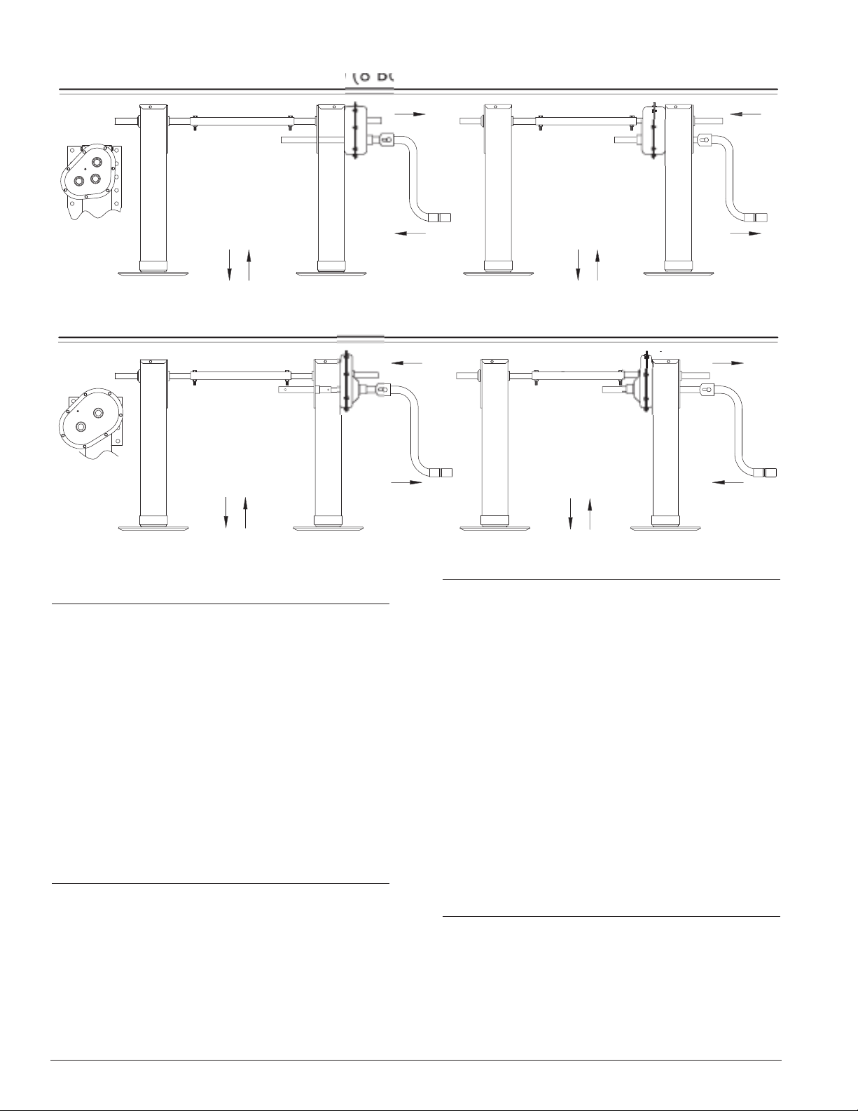
CONVENTONAL
PUSH CRANK IN FOR HIGH SPEED.
PULL CRANK OUT FOR LOW SPEED.
ROTATE CRANK COUNTERCLOCKWISE
TO EXTEND LANDING GEAR.
RO
TATE CRANK CLOCKWISE
T
O RETRACT LANDING GEAR.
CCW
CW
REVERSE
PULL CRANK OUT FOR HIGH SPEED.
PUSH CRANK IN FOR LOW SPEED
ROTATE CRANK CLOCKWISE
TO EXTEND LANDING GEAR.
RO
TATE CRANK COUNTERCLOCKWISE
T
O RETRACT LANDING GEAR.
HIGH
CW
LOW
HIGH
CCW
LOW
OPERATION
CONVENTONAL
PUSH CRANK IN FOR LOW SPEED.
PULL CRANK OUT FOR HIGH SPEED.
ROTATE CRANK CLOCKWISE
T
O EXTEND LANDING GEAR.
RO
TATE CRANK COUNTERCLOCKWISE
T
O RETRACT LANDING GEAR.
CW
CCW
HIGH
LOW
PULL CRANK OUT FOR LOW SPEED.
PUSH CRANK IN FOR HIGH SPEED
ROTATE CRANK COUNTERCLOCKWISE
T
O EXTEND LANDING GEAR.
RO
TATE CRANK CLOCKWISE
T
O RETRACT LANDING GEAR.
CWCCW
HIGH
LOW
OPERATION
Fast Gear
FROM TRAILER:
1. Position the trailer so that the landing gear
shoes will rest on a firm level surface when
landing gear is extended.
2. Shift landing gear to high gear and extend
landing gear until shoes contact ground.
3. Shift landing gear to low gear and lift trailer
approximately (1) inch.
4. Unlock fifth wheel, uncouple air lines, and
drive the tractor out from under the trailer.
LUBRICATION – STANDARD:
When manufactured, the landing gears have
been adequately greased with high quality
lubricant. It will be necessary to periodically
supplement this lubricant to maintain
satisfactory performance. Use a molybdenum
type grease with appropriate temperature
range for your operating conditions. Gearbox
leg has (3) grease fittings; leg without gearbox
has (2) gr
Prior to lubrication, extend legs approximately
1.
(2) inches fr
For optimum per
2.
lube both legs at all grease fittings.
ease fittings.
om maximum r
mance, ever
for
etracted position.
y (6) months
TO CONNECT TRACTOR
TO TRAILER:
1. Ensure that the trailer is at a sufficient height
to allow coupling of the tractor and trailer.
2. Connect air lines from tractor to trailer, then
lock trailer brakes and back tractor under
trailer, then lock fifth wheel.
3. Retract landing gears to fully retracted
position.
4. Store crank on the crank holder.
2
3. Add 1/4-lb grease at each grease fitting.
LUBRICATION – NoLube:
No additional grease is required.
XL-LG330-01 Rev. B

TROUBLE SHOOTING:
mal trailer operating service, certain components such as shafts, bushings, bearings, gears, and
In nor
screw and nut assemblies are subject to wear and will require replacement.
However, under extreme usage condition exceeding AAR-931 Durability Requirements the same
components may r
equire replacement more frequently.
Landing gears hard to crank–check the following:
PROBLEM SOLUTION
1. Cross driveshaft in a bind or tight Bolts must be loose and cross driveshaft free to
between shafts. move in slots provided.
2. To determine which leg turns hard Remove cross driveshaft bolt and crank each leg
on the jack shaft.
3. Inadequate lubrication. (See Lubrication Instructions).
4. Alignment. Legs must be timed together, parallel to each other
and perpendicular to the trailer crossmembers.
5. Upper housing or retracting tube may be bent. Replace damaged part.
6. Screw and nut assembly may have excessive Disassemble and inspect for wear. If screw and/or
wear and be hard to turn or inoperable. nut show considerable wear, then replace entire
retracting tube assembly.
7. Check for proper clearance between pinion Minimum end play 1/32˝.
and bevel gear.
8. Excessive wear or damage to pinion, bevel, Replace damaged gears.
input, idler and/or output gears.
9. Landing gear jack shafts and/or shift shaft Check to see if trailer mounting bracket has
binding. sufficient size clearance hole to miss landing gear
boss or shift shaft.
10. Bent retracting screw. Replace entire retracting tube assembly.
11. Damaged thrust bearing. Replace.
12. Damaged collar. Replace.
13. Damaged shift lock boss and/or shaft Replace.
bearing boss.
Weld blow through where strut bracket is Grind weld as required and re-weld.
14.
welded to housing. (With no-load on landing
gear, the retract tube should have free play
inside housing.)
15. Impact to jack shaft end has pressed bearing Press boss back into position.
boss into gearbox half.
Trouble Shooting/General:
1. Right-hand leg (gearbox leg) operates but Broken cross driveshaft bolt or damaged cross
left-hand leg does not move. driveshaft. Replace damaged part.
2. Legs will not operate when turning jack shaft. Damaged pinion or bevel gear. Replace damaged part.
3. Right-hand leg will not operate, shift shaft Damaged input, idler, and/or output gear. Replace
will turn but jack shaft does not turn. damaged part.
4. Leg locked and will not turn. Bent retracting screw or damaged riser nut and
screw. Replace entire retracting tube assembly.
5. Right-hand leg will not stay fully shifted in Shift lock ball and shift lock spring missing or
low gear. damaged shift lock spring. Replace missing or
damaged part.
6. Noisy gearbox. Check that shift shaft movement is 1˝ when shifted
between gears.
XL-LG330-01 Rev. B
3

CAUTIONS:
Landing gears are designed to meet T.T.M.A. recommended practice RP-4 and A.A.R.-931 requirements.
When operating the landing gears, it is necessary to observe some cautions. By doing so you will ensure long
ouble free service.
tr
Do not over extend or over retract landing gears.
1.
2. Never drop trailer on landing gears. Always extend landing gears until sand shoes
contact ground, then lift trailer approximately 1 inch before removing tractor
CAUTION
from trailer.
3. Always ensure that landing gear shoes or foot pads will rest on a hard ground
surface or concrete pad. If necessary, place shoes on a support plank to prevent
the landing gears from sinking into the ground surface. (This is especially
important with liquid cargo where a shift in the contents could overturn the
trailer!).
4. Always retract landing gears fully before moving the trailer.
5. Always store the crank on the crank holder after extending or retracting the
landing gear
.
6. Replace all damaged or missing parts.
7. Failure to replace worn or damaged riser nut and retracting screw assembly could
cause a failure.
1950 Industrial Blvd. • P.O. Box 425 • Muskegon, MI 49443-0425 • Phone 888-396-6501 • Fax 800-356-3929
Copyright © March 2005 • The Holland Group, Inc.
Holland USA, Inc. Facilities:
Dumas, AR Muskegon, MI
Holland, MI Warrenton, MO
Monroe, NC Wylie, TX
Ph: 888-396-6501 Fax: 800-356-3929
4
Holland International, Inc.
Holland, MI
Phone: 616-396-6501
Fax: 616-396-1511
HOLLAND USA, INC.
www.thehollandgroupinc.com
Holland Hitch of Canada, Ltd.
Woodstock, Ontario • Canada
Phone: 519-537-3494
Fax: 800-565-7753
Holland Equipment, Ltd.
Norwich, Ontario • Canada
Phone: 519-863-3414
Fax: 519-863-2398
Holland Hitch Western, Ltd.
Surrey, British Columbia • Canada
Phone: 604-574-7491
Fax: 604-574-0244
XL-LG330-01 Rev. B
 Loading...