

FIFTH WHEEL
OWNER’S
MANUAL
FW35-S09623 Series
Fifth Wheel
Installation, Operation, Inspection,
Maintenance Procedures and
Comprehensive Warranty
TECHNOLOGY
XL-FW504 Rev A
Questions or Comments?
Call
www.thehollandgroupinc.com
FIFTH WHEELS
1-888-396-6501

INSTALLATION INSTRUCTIONS
General Safety Information
It is important to read, understand, and follow the important information contained in
these installation instructions. Failure to do so may result in a hazardous condition or
cause a hazardous condition to develop.
All welding should be performed by an AWS certified welder using a low hydrogen
process and AWS E70XX filler metal. Failure to weld correctly may cause distortion,
damage, and/or result in insufficient strength and subsequent joint failure which,
if not avoided, could result in death or serious injury.
Prior to welding take precautions to ensure that the tractor electrical system is not
damaged due to the welding process.
Safety Signal Words
DANGER indicates an imminently hazardous situation which, if not
avoided, will result in death or serious injury.
WARNING indicates a potentially hazardous situation which, if not
avoided, could result in death or serious injury.
CAUTION indicates a potentially hazardous situation which, if not
avoided, may result in minor or moderate injury.
CAUTION used without the safety alert symbol indicates a potentially
hazardous situation which, if not avoided,
1. Keep Work Area Clean. Cluttered areas and benches invite accidents.
2. Keep fingers away from all potential pinch points in the fifth wheel.
3. All fifth wheel maintenance must be performed by a qualified service technician
using proper tools and safe procedures.
4. Use only genuine Holland parts.
Use Safety Goggles. Glasses or goggles not in compliance with ANSI or CSA can
5.
cause serious injury when damaged or broken.
Wear Proper Apparel. Do not wear loose clothing, gloves, neckties, jewelry (rings,
6.
wristwatches, etc.) that can get caught in moving parts. Non-slip footwear is
recommended.
may result in property damage.
Fifth Wheel Design and Intended Use:
1. For pulling trailers with standard SAE kingpins which are in good condition
and securely mounted or locked in position in the trailer.
2. For on-highway hauling applications.
3. Within the capacities stated in Holland literature.
4. As recommended in Holland literature (available from Holland or Holland
distributors).
Holland Fifth Wheels are NOT Designed or Intended For:
1. Use with non-SAE kingpins, such as kingpins which are bent, improper size or
dimensions, not secured to maintain SAE configuration, or which are installed in
warped trailer bolster plates.
2. Tow-away operations which damage or interfere with the proper operation of
the fifth wheel.
3. The attachment of lifting devices.
4. The transport of loads in excess of rated capacity.
5. Off-highway applications and use.
6. Applications other than recommended.
2
XL-FW504 Rev A

INSTALLATION INSTRUCTIONS
continued
Installation
General Recommendations
1. Every user and installer using Holland products either recommended or not recommended by
Holland, must thoroughly satisfy himself that the installation procedure used is appropriate
or the vehicle, product and application.
f
2. Consult the Holland literature for fifth wheel capacities and applications.
. Consult the tractor manufacturer’s body builder’s book and the latest SAE and D.O.T.
3
standards for additional installation methods. Holland recommends the
aintenance Practice 603Bfor installation procedures.
M
4. Determine the proper fifth wheel position, or, in the case of a sliding fifth wheel, the range of
proper positions. Proper positioning of the fifth wheel is important for weight distribution,
swing clearance and handling characteristics. See SAE J701a for proper placement, as well as
the tractor manufacturer’s body builder’s book.
5. Use Grade 8, 5/8˝ minimum diameter bolts and Grade “C” locknuts for mounting.
6. Bolt holes can be 1/32˝ larger in diameter than the bolt fastener. Bolts must be adequately
tightened using charted torque ranges in foot-pounds for the recommended Grade 8, 5/8˝
diameter bolts. Larger diameter Grade 8 bolts and coated fasteners may be used.
7. The bolts attaching the fifth wheel mounting angles to the truck frame require hardened
steel washers under both the bolt and under the locknut, unless flanged head bolts or
flanged head locknuts are employed.
8. A minimum of 5 bolts are required to attach each mounting angle to a frame rail, and the
distance between bolts must not exceed 8˝, except when cutouts are required in the
mounting angles.
9. Whenever a cutout is made on the mounting angle, such as required to bypass spring
hangers, a 1˝ minimum radius should be used and bolts should be placed within 1-1⁄2˝, but
not closer than 1˝ of the cut, fore and aft.
10. The mounting angle should have a minimum thickness as shown in
steel specification ASTM A 36.
11. When initially positioning the fifth wheel for frame holes, the full length of the fifth wheel or
slider mounting angles should seat flush on the top and side surface of the truck-tractor
frame rails where channel-type rails
are employed. There should not be a
gap over the top of the truck frame
rails. The base of the fifth wheel
assembly and of the mounting angle
members should seat flush on the top
of the frame rail to prevent flexing
and to give uniform weight
distribution. It is also recommended
to chamfer or smooth sharp edges
and corners of mounting materials
wherever contact is made with the
tractor frame.
12. If the fifth wheel is to be mounted using a mounting plate (bracket with mounting base),
result in structural failure of the installation with a potential loss of the fifth wheel assembly,
mounting structure, and/or trailer and may result in death or serious injury.
13. Trailer pick-up ramps ar
14. When mounting to aluminum frames, follow the tractor manufactur
15. Review, in addition, the specific information on the following pages for each type of fifth
CHART 1 for minimum plate thickness recommendations.
refer to
Do not use U-bolts in fifth wheel installations. Use only new Grade 8 bolts and
new Grade C lock nuts, sized 5/8˝ minimum diameter. Failure to do so may
ecommended at the r
e r
Holland has available a stationary mounting angle intended for use with aluminum frames.
Contact Holland or Holland distributors for availability.
wheel mounting, as well as “
publication.
Inspection and Lubrication Prior to Use” on page 8 of this
Fifth Wheel Mounting Angle Mounting Plate
Vertical Capacity Thickness Thickness
12,000 lbs. 1/4˝ 1/4˝
20,000 lbs. 5/16˝ 1/4˝
40,000/45,000 lbs. 5/16˝ 5/16˝
50,000/55,000 lbs. 3/8˝ 3/8˝
62,500/70,000 lbs. 1/2˝ 1/2˝
100,000 lbs. 3/4˝ 3/4˝
165,000 lbs. 3/4˝ 1˝
ear of the tr
CHART 1
Minimum Minimum
uck-tractor frame.
T.M.C. Recommended
Chart 1 and should be
ecommendations.
s r
er’
XL-FW504 Rev A
3
INSTALLATION INSTRUCTIONS
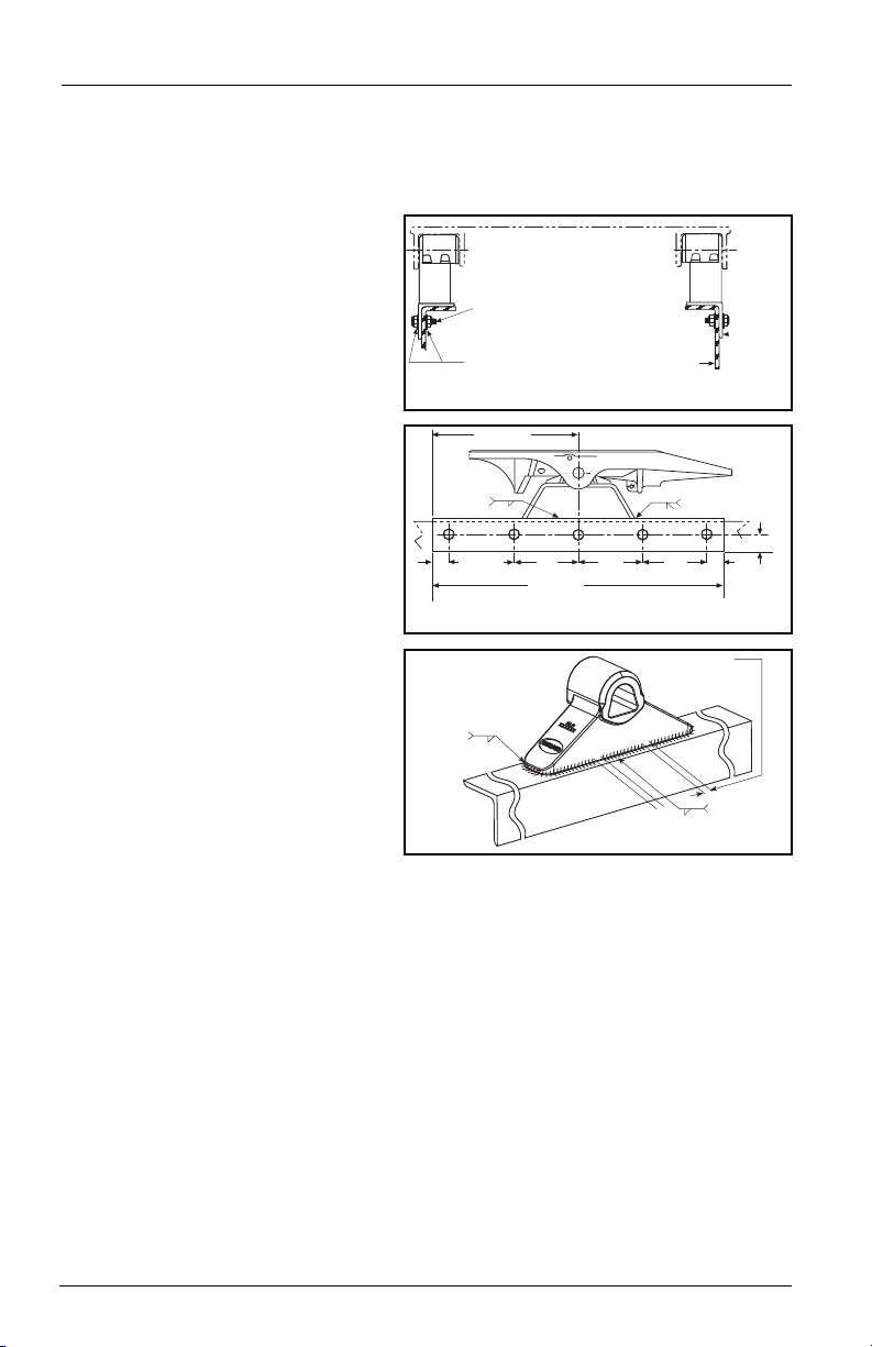
The full length of the fifth wheel mounting
angle should seat flush on the truck frame
when mounting to prevent flexing of
mounting angle and to give uniform
weight distribution along truck frame rail.
5/8˝ diameter Grade 8 bolts minimum size,
tightening torque to bolt manufacturer
c
harts.
Hardened steel washers or flanged lock
nuts (5/8˝ diameter Grade “C” lock nuts).
HDN. STEEL WASHERS
T
RUCK FRAME RAIL
See Chart 1
for minimum
mounting
angle
t
hickness
18.00˝ MIN.
3
6.00˝ MIN.
1
.00˝ MIN.
D
OUBLE PASS MIN.
BOTH ENDS
8.00˝ MAX. TYP.
(50.8mm)
2.00˝
(203.2mm)
1
/4˝
BOTH SIDES
8.00
˝
(
203.2mm)
(
203.2mm)
8
.00
˝
(
203.2mm)
8.00˝
(
914.4mm)
2.00˝
(
50.8mm)
1/2˝
(457.2 mm)
3
5
/1
6
GAP
1
/4˝-1/2˝ in 4 places
5
/16
Both ends
continuous
Both sides
center of
bracket
continued
Stationary Fifth Wheel Installation
Prior to proceeding with the installation of the stationary fifth wheel assembly, carefully
review the “General Safety Information” section on page 2.
Bracket with Mounting Angle
(see Figure 1A, 1B, and 1C):
1. Holland brackets with mounting
angle are provided with the bracket
welded in the center of a 36˝ long
angle with a 4˝ minimum
horizontal and 3-1/2˝ minimum
vertical leg size, and to a specific
tractor frame width. Verify that the
bracket and tractor frame width are
the same.
2. In addition to the information
given in “Installation: General
Recommendations” on page 3, follow
the recommendations in FIGURE 1.
Bracket for Angle Mounting
(see Figure 1A, 1B, and 1C):
1. Holland brackets for angle
mounting are intended to be
welded to mounting angles at the
time of installation.
2. See “Installation: General Recommen-
dations” on page 3, for angle
thickness and material (use 4˝
minimum horizontal and 3-1/2˝
minimum vertical leg size).
The recommended length of
each mounting angle is 36˝. It is
recommended that each angle
extend a minimum length of 18˝ forward of the fifth wheel pivot point, and not less
than 12˝ to the rear. If angles shorter than 36˝ are required, the special
recommendations of the tractor manufacturer should be obtained.
3. In addition to the information given in
follow the recommendations given in FIGURES 1A, 1B, and 1C. The following
sequence is suggested for both fabricated and cast brackets:
A. Securely position the mounting angle to the tractor frame.
B. Bolt the angles to the tractor as shown in FIGURES 1A and 1B.
C. Position the brackets on the angles and verify the correct spacing to mount
the fifth wheel.
D. For fabricated brackets (a welded asssembly), weld the bracket to the mounting
angle with 1/4˝ fillet welds on both sides, and 1/2˝ groove welds on both ends,
as shown in FIGURES 1A and 1B. The welds should be continuous around the
bracket and joined at the corners.
E. For cast brackets (single piece), weld with 5/16˝ fillet weld, as shown in
FIGURE 1C. The welds must be continuous ar
4
FIGURE 1C
(Cast Brackets Only)
WELDING DETAILS
“Installation: General Recommendations,”
FIGURE 1A (End View)
FIGURE 1B (Side View)
ound the bracket ends.
XL-FW504 Rev A
INSTALLATION INSTRUCTIONS
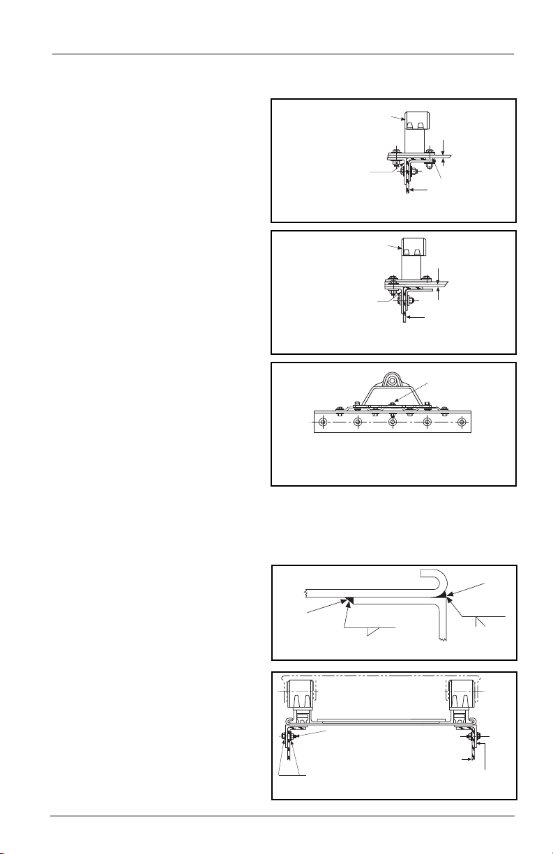
FIFTH WHEEL
SUPPORT BRACKET
FLAT MOUNTING PLATE
See Chart 1 for
minimum thickness
INBOARD ANGLE
T
RACTOR FRAME
SPACER
Attach the outboard angle to
tractor frame with hardware
listed in Figure 1A. Attach
mounting plate to angle
with same number of bolts
(
in addition to attachment to
fifth wheel support bracket).
Attach the outboard angle to
tractor frame with hardware
l
isted in Figure 1A. Attach
mounting plate to angle with
same number of bolts (in
a
ddition to attachment to
fifth wheel support bracket).
CORRUGATED
M
OUNTING PLATE
See Chart 1 for
minimum thickness
TRACTOR FRAME
FIFTH WHEEL
SUPPORT BRACKET
CENTER
BOLT
Attach bracket and mounting plate as shown.
Use center bolt of sufficient length to bolt through
bracket, mounting plate and mounting angle.
3/8˝ 3 - 8.50˝
5/16˝
3 - 8.50˝
INSIDE
WELD
OUTSIDE
WELD
See Chart 1 for min.
mounting angle
thickness
HARDENED STEEL
WASHERS
The full length of the fifth wheel mounting
angle should seat flush on the truck frame
when mounting to prevent flexing of
mounting angle and to give uniform
weight distribution along truck frame rail.
5/8” diameter Grade 8 bolts minimum size.
Tightening torque to bolt manufacturer charts.
Hardened steel washers or flanged locknuts.
5/8” diameter Grade “C” locknuts.
TRUCK FRAME RAIL
Stationary Fifth Wheel Installation continued
Bracket with Mounting Base
(See Figures 2A, 2B, and 2C):
1. Holland brackets with mounting
base are intended for installation
on either corrugated or flat
mounting plates.
continued
2. In addition to the information
given in “Installation: General
FIGURE 2A
Recommendations,” on page 3,
follow the recommendations in
FIGURES 2A, 2B, and 2C.
3. See “Installation: General
Recommendations” on page 3
for angle thickness and material.
The mounting angle should be 1˝
longer than the mounting plate,
FIGURE 2B
and be 36˝ minimum length.
Use 3˝ minimum horizontal and
3 -1/2˝ minimum vertical leg size.
Longer horizontal legs may be
required with narrow frame widths.
FIGURE 2C
Sliding Fifth Wheel Installation
Prior to proceeding with the installation of the sliding fifth wheel assembly,
carefully review the
Inboard Angle Mounting
(See Figures 3 and 4):
1. Angles must be installed on the
sliding fifth wheel base plate to
facilitate mounting. See “Installation:
General Recommendations,” on page
3, for angle thickness and material.
“General Safety Information” section on page 2.
FIGURE 3
2. Use a mounting angle which is at
least 2˝ longer than the slide base
plate and 36˝ minimum length.
Use 4˝ minimum horizontal and
3-1/2˝ minimum vertical leg size.
The fifth wheel top plate and support
bracket may be removed fr
base plate for ease of handling.
XL-FW504 Rev A
om the
FIGURE 4 (End View)
5
INSTALLATION INSTRUCTIONS
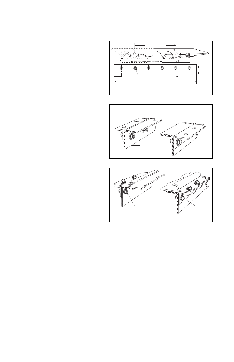
1.00˝
(25.4 mm) MIN.
CENTER LINE OF
TRACTOR REAR
A
XLE(S) OR
BOGIE
P
LATE LENGTH PLUS 2.00˝ MIN. (50.8 mm)
4.00˝
(101.6 mm)
m
ax.
1˝ min. 6 bolts equally spaced
FORWARD TRAVEL
T
RUCK FRAME RAIL
T
he full length of the fifth wheel mounting angle should seat flush on
the truck frame when mounting to prevent flexing of mounting angle
and to give uniform weight distribution along truck frame rail.
5/8˝ diameter Grade 8 bolts minimum size,
tightening torque to bolt manufacturer charts.
Hardened steel washers or flanged locknuts.
5/8˝ diameter Grade “C” locknuts.
HARDENED STEEL
WASHERS
continued
Sliding Fifth Wheel Installation continued
Inboard Angle Mounting continued
3. Position the angles on the slide
plate for the required frame width.
Be sure to keep the plate centered
left to right, and front to rear on
the mounting angles.
4. Weld as shown in FIGURE 3. Make
F
5/16˝fillet welds inside and 3/8˝
IGURE 4 (Side View)
groove welds on the outside with
skip welds 3˝ long on
approximately 8-1/2˝ centers (weld
3˝, skip 5-1/2˝). Weld inside
opposite skips on the outside. ALSO
The plate to the top of the
WELD:
angle at the ends of the plate.
5. Attach the slider plate and
mounting angles to the tractor
using recommendations in
“General Recommendations”
and in FIGURE 4.
6. Reassemble the fifth wheel top
plate and bracket sub-assembly to
the slider base plate if they were
removed previously.
Outboard Angle Mounting
(See Figures 5 and 6):
1. If angles are not installed, see “Installation: General Recommendations,” on page 3, for
thickness and material. Use 3˝ minimum horizontal and 3-1/2˝ minimum vertical
leg size. Longer horizontal legs may be required with narrow frame widths. The
recommended length of each mounting plate is the same length as the slide base
mounting plate.
2. In addition to the information given in
on page 2, follow the recommendations in FIGURE 5 and FIGURE 6. The following
sequence is suggested:
A. Securely position the mounting angles to the tractor frame and attach as shown
in FIGURE 5. Follow the bolting recommendations as shown in FIGURE 4. Angles
must be flush with the top of the tr
B. Locate the slide base and center left to right and fr
angles. Clamp in place and drill 21/32˝ diameter holes using the mounting
plate as a template if holes are not provided in the angle.
C. Align holes in the slide plate with outboard angle mounting holes and bolt
using Grade 8 fasteners, hardened steel washers and Grade C locknuts, properly
tightened, (see
6
FIGURE 6). Use all mounting holes on the fifth wheel.
“Installation: General Recommendations,”
uck frame.
ear on the mounting
ont to r
XL-FW504 Rev A
FIGURE 5
FIGURE 6

INSTALLATION INSTRUCTIONS
PLUNGER ADJ. BOLT
POCKET
PLUNGER
RACK
BRACKET CAP
1/8”
1/4”-1/2”
Locate and weld the
rear slide stops per steps
2 through 5 above.
Weld the forward side
in the center only
to avoid interference
with the bracket.
TYP.
5/16˝
Dimensions apply
after welding.
TYP.
5/16˝
SLIDE STOP
continued
Sliding Fifth Wheel Installation continued
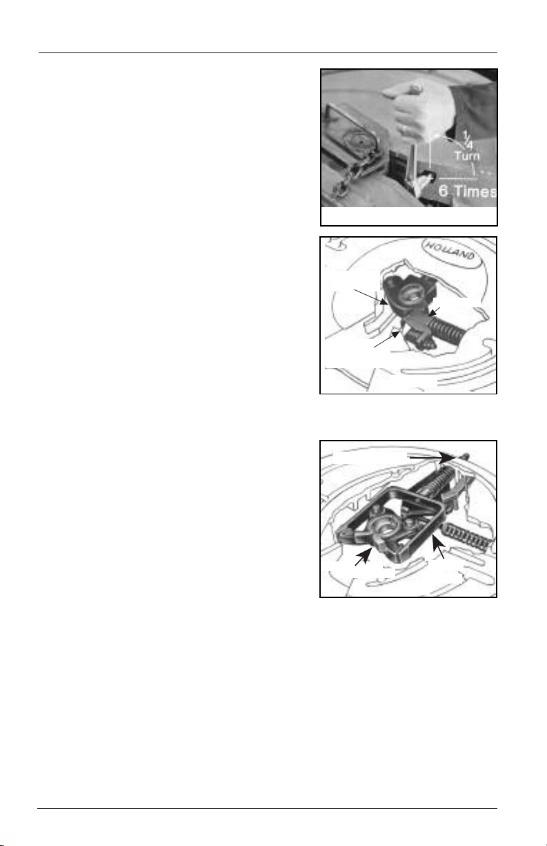
Adjustment of Sliding Bracket Locking Plungers
The slide locking plungers are given a preliminary adjustment during factory assembly.
However, due to variations introduced during mounting (such as frame and material
tolerances) a final adjustment must be made at the time of installation.
Adjust the locking plungers at installation, after one month of service,
and at recommended maintainence intervals. by use of the adjusting
bolts provided on both sides. Failure to do so may result in accelerated wear of
components, lower service life, improper load transfer, or improper load distribution.
To adjust locking plungers:
1. Loosen lock nut and turn adjusting bolt
out (counterclockwise). See FIGURE 7.
2. Disengage and engage the locking
plungers. Check that the plungers are
securely seated without binding.
3. Turn the adjusting bolt in (clockwise)
until it contacts the rack. Turn the bolt
an additional 1/2 turn then tighten the
locking nut securely.
FIGURE 7
(Outside View)
Prior to proceeding with the installation of the sliding fifth wheel assembly, carefully
review the
“General Safety Information” section on page 2.
Installation of Slide Stops
1. It is the responsibility of the installer
to insure that slide stops are installed
properly at all four corners of the
slider plate.
2. Slide the bracket to the full rear
position and engage the plungers in
the rack.
3. Locate rear stops under the curled
edge allowing some clearance to the
bracket (approximately 1/8˝). Clamp
in place. This should position the
stops approximately 1/4˝ to 1/2˝
from the edge of the rear of the plate,
FIGURES 8A and 8B.
see
4. Slide bracket ahead out of the way
and weld the stops in place as shown
in FIGURES 8A and 8B. The welds
should be 5/16˝ fillet.
5. Slide the bracket to the full r
position and check for clearance.
bracket seat properly into the rack
with all teeth engaged.
6. Repaint as required.
XL-FW504 Rev A
Make sure the plungers on the sliding
ear
FIGURE 8A
FIGURE 8B (Rear End View)
7

INSTALLATION INSTRUCTIONS
continued
Attachment of Air-Activated Slide Release – If Required
1. Mount the cab control valve in accordance with the instructions provided. It should
be readily accessible to the driver, but protected to prevent accidental activation.
2. Attach an air line, using appropriate fittings to the “air” or “in” port of the valve.
Use an air source recommended by the tractor manufacturer. Use fittings and lines
of suitable pressure rating.
3. Connect an air line between the “cyl” or “out” port of the valve and the active side
of the air cylinder. A bulkhead fitting may be placed at the front of the slide base
plate, if desired. Use fittings and lines of suitable pressure rating and be sure line is
run so as not to interfere with any other operation or component.
4. Check operation of the valve and cylinder.
Inspection and Lubrication Prior to Use
1. Review the installation. Be sure all nuts and bolts are in place and properly
tightened. Be sure all necessary steps were properly followed and that all
components removed to facilitate installation are reinstalled.
2. Check the fifth wheel locking mechanism with a Holland TF-TLN-5001 (2˝) or
TF-TLN-1500 (3-1/2˝) Lock Tester. Examine for proper locking as described in the
“Operating Instructions” of this manual. This must be done to assure that the
mechanism has not been damaged by shipment, handling, or storage.
Failure to properly install, operate, or maintain this fifth wheel could
result in tractor and trailer separation causing death or serious injury
to others.
3. Apply grease to the bearing surface of the support bracket through the grease
fittings on the side or front of the fifth wheel pockets. The top plate must
be lifted up slightly to ensure proper application of grease. (NOTE: This is not
required on Holland LowLube and NoLube top plates.)
4. Apply a generous coating of grease to the top of the fifth wheel plate, where it will
contact the trailer plate. (
NoLube top plates.)
5. Apply a generous coating of grease to the front lock and lock jaws.
8
NOTE: This is not required on Holland LowLube and
XL-FW504 Rev A

OPERATING INSTRUCTIONS
1. Failure to read, understand, and follow the important information
contained herein may result in a hazardous condition or cause a
hazardous condition to develop.
2. Relative to tractor-trailer operations, there are other checks,
inspections, and procedures not listed here, which are necessary,
prudent, and/or required by law. The following is in addition to
these, and pertains to the fifth wheel only.
3. Perform these procedures with the area clear of obstacles and other
personnel.
Coupling Procedures
1. Check out the equipment before coupling.
A. Make sure that the fifth wheel is properly lubricated, that the locks are open,
and that the ramps are tilted down in the proper position.
B. Make sure the mounting of the fifth wheel to the tractor frame is in good
condition and is tight.
2. Back up close to the trailer, centering the kingpin on the throat of the fifth wheel.
STOP.
3. Block the trailer wheels, connect the brake lines and light cord. Be sure any slack in
the lines is supported so the brake lines do not become tangled. Set the trailer
brakes.
4. Check to see that the trailer is at the proper height for coupling. The leading edge
of the trailer upper coupler plate should initially contact the fifth wheel top bearing
surface 4" to 6" behind its pivot axis as the tractor backs under the trailer. Using low
gear, raise or lower the trailer landing gear as required to obtain this position.
Attempting to couple with the trailer at an improper height could
result in a false or improper coupling and cause damage to the tractor,
fifth wheel, or trailer.
5. Back under the trailer, keeping the trailer kingpin centered in the throat of the fifth
wheel.
6. After picking up the trailer with the fifth wheel —
until the fifth wheel locks firmly on the kingpin. Stopping helps prevent hitting the
kingpin too hard.
7. Back up tightly against the kingpin. Then pull forward to test the completeness of
the coupling as an INITIAL check.
STOP — then continue backing
XL-FW504 Rev A
9

OPERATING INSTRUCTIONS
WHEN LOCKED WITH LOCKS PROPERLY ADJUSTED,
THE YOKE WILL BE SEATED AS SHOWN AND THE
NUT AND WASHER WILL BE SNUG AGAINST THE
FIFTH WHEEL.
BOLSTER PLATE
FLUSH WITH
FIFTH WHEEL
LOCKS
CLOSED
KINGPIN PROTRUDES
BELOW LOCKS
PLUNGER
NO GAP
BOLSTER PLATE FLUSH WITH FIFTH WHEEL
WHEN LOCKED, SWINGING LOCK (JAW) MUST BE
AROUND KINGPIN AND LOCKING PLUNGER MUST
BE VISIBLE AS SHOWN AS VIEWED FROM THE
REAR OF THE TRACTOR.
continued
Coupling Procedures continued
A direct visual inspection is required to assure proper coupling. Improper
coupling can pass the initial pull test. Sound is unreliable. Do not take for
granted that you are properly couple. Get out of the cab and look.
8. Visually check to see that the kingpin
is in the fifth wheel locks, not
overhanging the fifth wheel or caught
in a grease groove. There should be no
gap between the trailer bolster plate
and the fifth wheel. (See FIGURE 1 and
FIGURE 2A.) Check for proper coupling
by looking into the throat of the fifth
wheel. Check the locks as shown in
FIGURE 1 for Type “A” locks and
FIGURES 2A and 2B for Type “B” locks.
If you do not obtain a
proper coupling, repeat
this sequence. Do not use any fifth wheel
which fails to operate properly.
9. If your fifth wheel is equipped with a
manual secondary lock, engage it.
10. Using low gear, retract the landing
gear until unloaded. Then, shift to
high gear and continue cranking until
they are fully retracted. Fold down or
remove the crank handle and place it
in the crank handle holder.
11. Check the brake lines and light cord.
12. Remove the wheel blocks and continue
with pre-trip inspection.
TYPE ‘A’ LOCK
FIGURE 1
TYPE ‘B’ LOCK
VIEW LOOKING INTO
THROAT OF FIFTH WHEEL
FIGURE 2A
TYPE ‘B’ LOCK
10
FIGURE 2B
XL-FW504 Rev A

OPERATING INSTRUCTIONS
UNLOCKED
(RELEASED)
LOCKED
(ENGAGED)
UNLOCKED
(RELEASED)
LOCKED
(ENGAGED)
continued
Uncoupling Procedures
1. Set trailer brakes with tractor protection switch.
2. Back into the kingpin and set emergency brake on the tractor.
3. Block the trailer wheels.
4. Wind down the landing gears in high gear until they touch the ground. Shift to low
gear and crank a few extra turns. Do not raise the trailer off the fifth wheel. It may
be necessary to provide a base for the landing gear in poor parking conditions. Fold
down or remove the crank handle and place it in the crank handle holder.
5. Disconnect the light cord and brake lines. Attach the dummy air coupling to keep
foreign material from entering the brake lines.
6. Unlock the fifth wheel, including the manual secondary lock if so equipped.
7. Release the tractor emergency brake and pull out slowly from under the trailer. Let
the trailer slide down the fifth wheel and pick-up ramps, being careful that the
trailer landing gear touches the ground with minimal impact.
NOTE: When uncoupling the Type A fifth wheel, it is normal for the release handle to
move to the closed position. It is not necessary to pull the release handle to recouple.
Sliding Procedure for a Sliding Fifth Wheel
1. Stop the tractor and trailer in a straight line on level
ground. Lock the trailer brakes.
The trailer must be stopped and the trailer
brakes locked to prevent damage to the
tractor or trailer by uncontrolled sliding of the fifth wheel.
2. Release slide locking plungers as detailed below for
the type of slide release:
A. Air Slide Release - put cab control valve to the
unlock position.
B. Manual Slide Release - pull release lever. See
FIGURE 3.
3. Check to see that both plungers have released as
shown in
FIGURE 3 and 4. If plungers do not come
out, lower the landing gear to relieve pressure on
the plungers. This also allows the fifth wheel to slide
easier.
4. Drive the tractor forward or backward slowly to
position the fifth wheel.
5. After sliding the fifth wheel to the desired setting,
engage the slide locking plungers as below:
A. Air Slide Release - put control valve in lock
position to retract plungers.
B. Manual Slide Release - trip release arm to allow
plungers to retract.
6. Visually check to see that both plungers are retracted
and fully engaged. Leaving the trailer brakes locked
and moving the tractor slightly may be necessary to
engage the plungers in the rack teeth. Raise the
landing gear to the fully retracted position.
Do not operate the vehicle if the plungers are not fully engaged and
landing gears are not fully retracted, as damage to the tractor, trailer,
and landing gears may occur.
XL-FW504 Rev A
MANUAL SLIDE RELEASE
FIGURE 3
FIGURE 4
AIR SLIDE RELEASE
11

INSPECTION PROCEDURE
Your Holland fifth wheel (or rebuild kit) is equipped with an
tractors with sufficient clearance between the tires and fifth wheel release handle.
After installation or rebuilding of the fifth wheel, the vehicle must be inspected to
insure proper clearance between the handle and the fifth wheel.
EXTENDED LENGTH RELEASE HANDLE. It is only to be used on
Inspection Procedure
After mounting the fifth wheel to the tractor frame, measure the distance between the
fifth wheel release handle and tractor tires with the release handle in the “open” or
“ready-to-couple” position. Rotate (“articulate”) the fifth wheel forward, as shown in
Figure 2, and measure the clearance.
1. Verify that the fifth wheel handle is in the “open” or “ready-to-couple” position.
EXTENDED
RELEASE
HANDLE
(XA-S09623)
8.0˝
2. Verify that the fifth wheel handle-to-tractor tire clearance is 3/0˝ or greater, as shown.
RELEASE
HANDLE
3.0˝
MINIMUM
TRACTOR TIRE
If the clearance in any position is less than .30˝, the extended handle
used, and a standard length release handle must be used. Contact Holland at
(888) 396-6501 for assistance.
3. If you are rebuilding a FW35-S09623-1 or FW35-S09623-2 fifth wheel, follow all
instructions in Holland publication XL-FW290. EXCEPTION: Use the extended
release handle (XA-S09623) for Item 23 in place of the standar
(XA-07171-1).
LOCKS OPEN
“READY TO COUPLE”
CANNOT be
elease handle
d r
12
XL-FW50
4
Rev A

MAINTENANCE PROCEDURES
1. Failure to read, understand, and follow the important information
contained herein may result in a hazardous condition or cause a
hazardous condition to develop.
2. All maintenance must be performed by a qualified person using
proper tools and safe procedures.
3. All maintenance must be performed while the tractor is uncoupled
from the trailer.
As-Needed Lubrication
1. Keep a water-resistant lithium-base grease applied to the trailer contact surface of
the fifth wheel plate.
2. Apply grease to the bearing surface of the support bracket through the grease
fittings on the side of the fifth wheel plate. The plate must be lifted up slightly to
relieve weight on the bracket while applying grease.
3. Spray diesel oil on the rack and slide path of the bracket on sliding fifth wheels.
Periodic Inspections and Adjustments
NOTE: All of the following must be performed every 30,000 miles or 3 months,
whichever comes first. Perform the inspections after steam cleaning to assure a good
inspection.
Inspection — General
1. Inspect the fifth wheel mounting. Check torque and replace any missing or
damaged bolts. Check for broken or distorted components and repair or replace as
needed.
2. Inspect the fifth wheel assembly for bent, worn or broken parts. Replace with
HOLLAND parts only.
Fifth Wheel Locking Mechanism Inspection and Adjustment
1. Check the operation of the fifth wheel locking mechanism using a HOLLAND
TF-TLN-1000 (2˝ kingpin) or TF-TLN-1500 (31/2˝ kingpin) Lock Tester. Inspect for
proper locking as described in the “Operating Instructions” in this manual.
Do not use any fifth wheel which does not operate properly.
2. Check adjustment of the fifth wheel locks and adjust as required. Use the procedure
as follows for the appropriate locking mechanism. If the locks cannot be properly
adjusted due to wear, the fifth wheel must be rebuilt or replaced. Contact your
HOLLAND Distributor to order the appropriate rebuilding kit or fifth wheel.
Improper adjustment can cause improper locking of the mechanism.
XL-FW504 Rev A
13
MAINTENANCE PROCEDURES
SPLIT LOCKS
LOCK ADJ. NUT
YOKE
S
WINGING
LOCK
LOCK
ADJUSTMENT
SCREW
PLUNGER
continued
Type “A” Lock Adjustment
The lock adjustment screw is found in the crotch
on the right side as shown (FIGURES 1 & 2).
1. Close the locks with the lock tester.
2. Tighten the adjustment screw by turning
clockwise until tight, using a 1/2˝ Allen
wrench or Allen socket extension.
3. Loosen the adjustment screw by turning it
counterclockwise 11⁄2turns. The locks are
now properly adjusted.
FIGURE 1
4. Verify this adjustment by locking and
unlocking several times.
FIGURE 2
Type “B” Lock Adjustment
1. Close the locks and insert a 2˝ plug
(HOLLAND P/N TF-0237) in the locks.
2. Check for a tight fit. The plug should be snug,
but you should be able to rotate it by applying
some force.
3. If the plug fits loosely, tighten by rotating the
nut on the shank counterclockwise. It may be
necessary to tap the end of the yoke shank
lightly to allow the nut to seat against the top
plate.
4. Repeat this procedure until the plug fits snug but can still be rotated. The locks are
now properly adjusted.
5. Verify proper operation of the locking mechanism using the lock tester.
FIGURE 3
14
XL-FW50
4
Rev A

MAINTENANCE PROCEDURES
PLUNGER
ADJ. BOLT
POCKET
PLUNGER
RACK
Relubrication After Inspection and Adjustment
Relubricate by applying a light rust-resistant oil to all moving parts.
Fifth Wheel Sliding Mechanism Inspection and Adjustment
1. Adjustment of Locking Plungers:
A. Loosen lock nut and turn
adjusting bolt (counterclockwise).
See FIGURE 4.
B. Disengage and engage the locking
plungers. Check that the plungers
are securely seated without binding.
Turn adjusting bolt in (clockwise) until
it contacts the rack. Turn adjusting
bolt an additional 1/2 turn, then
tighten the locking nut securely.
2. When Locking Plungers Won’t Release
to Permit Sliding of the Fifth Wheel:
A. Check the air cylinder for proper
operation and replace if necessary.
B. Check plunger adjustment.
C. If adjusted plunger binds on the
pocket (FIGURE 5), grind the top
plunger edges 1/16˝, reinstall and
adjust as above. Use a HOLLAND
TF-TLN-2500 Spring Compressor
to remove and reinstall the plunger.
3. When Locking Plungers Are Too Loose:
A. Check plunger adjustment.
B. Check the plunger springs for proper compression. Replace is necessary.
C. Check for plunger wear and replace if necessary. Use a HOLLAND TF-TLN-2500
Spring Compressor to remove and reinstall the plungers. Adjust the plungers as
described above.
Proper adjustment of the sliding bracket locking plungers must be
performed at installation and maintained at regular intervals by use of
the adjusting bolts provided on both sides. Proper adjustment is required for proper
operation and for proper load transfer and distribution.
COMMERCIAL PRODUCTS WARRANTY
HOLLAND warrants all Commercial Products (products
other than those normally used for personal, family
or household purposes) manufactured by it, when
properly installed, to be free from defects in material
and workmanship under nor
period of two (2) years from the date of manufactur
with the exception of elevating fifth wheels for which
the warranty period is ninety (90) days. This warranty
is void with respect to any product which has been
altered in any way from its manufactured condition,
such as intentional modification, accident, cor
misuse, failure to provide necessary and reasonable
maintenance and is exclusive from normal wear. The
sole responsibility of HOLLAND under this warranty is
limited to repairing or replacing at the factory any part
or parts which are returned, with transportation
charges prepaid, and are found to be defective to the
XL-FW504 Rev A
mal use and service for a
osion,
r
satisfaction of HOLLAND. Written authorization fr
HOLLAND must be obtained prior to returning this
warranty. HOLLAND shall not be liable in any event,
for proximate, incidental, consequential or other
damages, including but not limited to damages for
e,
loss of production or injury to persons or property arising
out of any breach of this warranty.
THERE ARE NO WARRANTIES, EXPRESS OR IMPLIED,
INCLUDING THE WARRANTY OF MERCHANTABILITY OR
A WARRANTY OF FITNESS FOR A PARTICULAR PURPOSE
EXTENDING BEYOND THAT SET FORTH ABOVE.
Holland reserves the right, without giving prior notice, to
change specifications and dimensions as designs are altered
or improved. Options other than those shown may be
provided. Contact the factory for information.
FIGURE 4
CHECK FOR POSSIBLE
INTERFERENCE
FIGURE 5
continued
om
15

16
XL-FW50
4
Rev A

XL-FW504 Rev A
17

18
XL-FW50
4
Rev A

WARRANTY
5-YEAR
COMPREHENSIVE
WARRANTY
olland warrants all fifth wheel commercial products
H
other than those normally used for personal, family,or
(
household purposes) manufactured after July 1,1990, to
be free from defects in material or workmanship for a
period of 5 years from the date of manufacture, except
elevating fifth wheels, which will carry a 180-day
warranty.This warranty covers only defects in materials
or workmanship and does not cover failures due to any
of the following:
1. Normal wear
2. Improper installation
3. Intentional modification
4. Accident
This warranty does not guarantee a particular service
life of the product since service life will vary with
application, degree of use, operating environment, level
of maintenance, and other factors beyond our control.
Holland’s sole responsibility for any fifth wheel product
or part determined by Holland to be defective and
covered by this warranty is limited to repairing or
replacing the product or part, and to providing an
allowance to be applied to the labor cost of removal
and replacement.
Prior authorization from Holland must be obtained
before replacing or returning any part, or incurring any
labor cost for removal.
incurred in parts, labor,or transportation by
unauthorized persons will be allowed under this
warranty. Holland reserves the right to request the
return of any part or fifth wheel assembly (with
transportation charges prepaid) claimed to be covered
by this warranty.
Holland shall not be liable, in any event, for proximate,
incidental, consequential,special, or other damages,
including — but not limited to — damages for loss of
production, loss of profits, loss of opportunity,or injury
to persons or property arising out of any breach of this
warranty.
THERE ARE NO WARRANTIES, EXPRESS OR
IMPLIED, INCLUDING THE WARRANTY OF
MERCHANT
A PARTICULAR PURPOSE, OR ANY OTHER
ARRANTY EXTENDING BEYOND THA
W
FORTH ABOVE.
ABILITY, WARRANTY OF FITNESS FOR
5. Corrosion
6. Misuse
7. Failure to provide
reasonable maintenance
No charges for expense
Warranty
T SET
XL-FW504 Rev A
19

20
Copyright © July 2005 • The Holland Group, Inc.
maintain this fifth wheel could result in
tractor and trailer separation causing death
or serious injury to others.
operation, and maintenance of this product. Read and
Failure to properly install, operate, or
understand this information.
IMPORTANT: Enclosed is important information for the installation,
XL-FW504 Rev A
 Loading...