

OWNER’S
MANUAL
FleetMaster LowLube Series
Fifth Wheels with Manual
Sliding Secondary Lock
XA-201-S10217, XA-201-S10579
& XA-231-S10217
Installation, Operation,
Maintenance Procedures and
Comprehensive Warranty
FIFTH WHEEL
TECHNOLOGY
XL-FW503 Rev B
Questions or Comments?
Call
1-888-396-6501
www.safholland.us
LOWLUBE

INSTALLATION INSTRUCTIONS
General Safety Information
It is important to read, understand, and follow the important information contained in
these installation instructions. Failure to do so may result in a hazardous condition or
cause a hazardous condition to develop.
All welding should be performed by an AWS certified welder using a low hydrogen
process and AWS E70XX filler metal. Failure to weld correctly may cause distortion,
damage, and/or result in insufficient strength and subsequent joint failure which,
if not avoided, could result in death or serious injury.
Prior to welding take precautions to ensure that the tractor electrical system is not
damaged due to the welding process.
Safety Signal Words
DANGER indicates an imminently hazardous situation which, if not
avoided, will result in death or serious injury.
WARNING indicates a potentially hazardous situation which, if not
avoided, could result in death or serious injury.
CAUTION indicates a potentially hazardous situation which, if not
avoided, may result in minor or moderate injury.
CAUTION used without the safety alert symbol indicates a potentially
hazardous situation which, if not avoided, may result in property damage.
1. Keep Work Area Clean. Cluttered areas and benches invite accidents.
2. Keep fingers away from all potential pinch points in the fifth wheel.
3. All fifth wheel maintenance must be performed by a qualified service technician
using proper tools and safe procedures.
4. Use only SAF-HOLLAND original parts.
5. Use Safety Goggles. Glasses or goggles not in compliance with ANSI or CSA can
cause serious injur
6. Wear Proper Apparel. Do not wear loose clothing, gloves, neckties, jewelry (rings,
wristwatches, etc.) that can get caught in moving parts. Non-slip footwear is
recommended.
y when damaged or broken.
Fifth Wheel Design and Intended Use:
1. For pulling trailers with standard SAE kingpins which are in good condition
and securely mounted or locked in position in the trailer.
2. For on-highway hauling applications.
3. Within the capacities stated in SAF-HOLLAND literature.
4. As recommended in SAF-HOLLAND literature (available from www.safholland.us).
Holland Fifth Wheels are NOT Designed or Intended For:
1. Use with non-SAE kingpins, such as kingpins which are bent, improper size or
dimensions, not secured to maintain SAE configuration, or which are installed in
warped trailer bolster plates.
2. Tow-away operations which damage or interfere with the proper operation of
the fifth wheel.
3. The attachment of lifting devices.
4. The transport of loads in excess of rated capacity.
5. Off-highway applications and use.
6. Applications other than recommended.
2 XL-FW503 Rev B

INSTALLATION INSTRUCTIONS
continued
Installation
General Recommendations
1. Every user and installer using SAF-HOLLAND products either recommended or not
recommended by
procedure used is appropriate for the vehicle, product and application.
2. Consult the
3. Consult the tractor manufacturer’s body builder’s book and the latest SAE and D.O.T.
standards for additional installation methods.
Recommended Maintenance Practice 603B for installation procedures.
Determine the proper fifth wheel position, or, in the case of a sliding fifth wheel, the range of
4.
proper positions. Proper positioning of the fifth wheel is important for weight distribution,
swing clearance and handling characteristics. See SAE J701a for proper placement, as well as
the tractor manufacturer’s body builder’s book.
5. Use Grade 8, 5/8˝ minimum diameter bolts and Grade “C” locknuts for mounting.
6. Bolt holes can be 1/32˝ larger in diameter than the bolt fastener. Bolts must be adequately
tightened using charted torque ranges in foot-pounds for the recommended Grade 8, 5/8˝
diameter bolts. Larger diameter Grade 8 bolts and coated fasteners may be used.
7. The bolts attaching the fifth wheel mounting angles to the truck frame require hardened
steel washers under both the bolt and under the locknut, unless flanged head bolts or
flanged head locknuts are employed.
8. A minimum of 5 bolts are required to attach each mounting angle to a frame rail, and the
distance between bolts must not exceed 8˝, except when cutouts are required in the
mounting angles.
9. Whenever a cutout is made on the mounting angle, such as required to bypass spring
hangers, a 1˝ minimum radius should be used and bolts should be placed within 1-1⁄2˝, but
not closer than 1˝ of the cut, fore and aft.
10. The mounting angle should have a minimum thickness as shown in Chart 1 and should be
steel specification ASTM A 36.
11. When initially positioning the fifth wheel for frame holes, the full length of the fifth wheel or
slider mounting angles should seat flush on the top and side sur
frame rails where channel-type rails
are employed. There should not be a
gap over the top of the truck frame
rails. The base of the fifth wheel
assembly and of the mounting angle
members should seat flush on the top
of the frame rail to prevent flexing
and to give uniform weight
distribution. It is also recommended
to chamfer or smooth sharp edges
and corners of mounting materials
wherever contact is made with the
tractor frame.
12. If the fifth wheel is to be mounted using a mounting plate (bracket with mounting base),
refer to CHART 1 for minimum plate thickness recommendations.
result in structural failure of the installation with a potential loss of the fifth wheel assembly,
mounting structure, and/or trailer and may result in death or serious injur
13. Trailer pick-up ramps are recommended at the rear of the truck-tractor frame.
When mounting to aluminum frames, follow the tractor manufacturer’s recommendations.
14.
SAF-HOLLAND has available a stationary mounting angle intended for use with aluminum
frames. Contact
15. Review, in addition, the specific information on the following pages for each type of fifth
wheel mounting, as well as “Inspection and Lubrication Prior to Use” on page 8 of this
publication.
SAF-HOLLAND, must thoroughly satisfy himself that the installation
SAF-HOLLAND literature for fifth wheel capacities and applications.
SAF-HOLLAND recommends the T.M.C.
face of the truck-tractor
CHART 1
Fifth Wheel Mounting Angle Mounting Plate
Vertical Capacity Thickness Thickness
12,000 lbs. 1/4˝ 1/4˝
20,000 lbs.
40,000/45,000 lbs. 5/16˝ 5/16˝
50,000/55,000 lbs. 3/8˝ 3/8˝
62,500/70,000 lbs. 1/2˝ 1/2˝
100,000 lbs. 3/4˝ 3/4˝
165,000 lbs. 3/4˝ 1˝
Do not use U-bolts in fifth wheel installations. Use only new Grade 8 bolts and
new Grade C lock nuts, sized 5/8˝ minimum diameter. Failure to do so may
SAF-HOLLAND or distributors of Holland brand products for availability.
Minimum Minimum
5/16˝ 1/4˝
y.
XL-FW503 Rev B 3
INSTALLATION INSTRUCTIONS
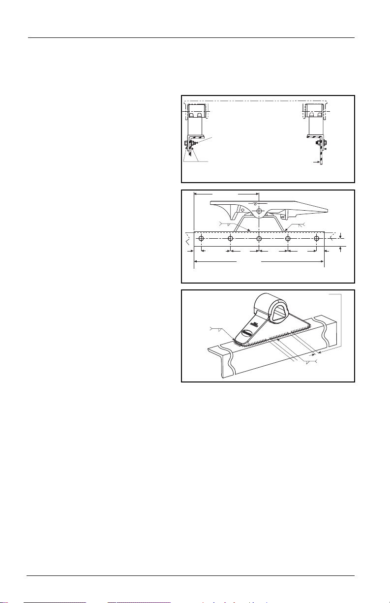
The full length of the fifth wheel mounting
angle should seat flush on the truck frame
when mounting to prevent flexing of
mounting angle and to give uniform
weight distribution along truck frame rail.
5/8˝ diameter Grade 8 bolts minimum size,
tightening torque to bolt manufacturer
charts.
Hardened steel washers or flanged lock
nuts (5/8˝ diameter Grade “C” lock nuts).
HDN. STEEL WASHERS
TRUCK FRAME RAIL
See Chart 1
for minimum
mounting
angle
thickness
18.00˝ MIN.
36.00˝ MIN.
1.00˝ MIN.
DOUBLE PASS MIN.
BOTH ENDS
8.00˝ MAX. TYP.
(50.8mm)
2.00˝
(203.2mm)
1/4˝
BOTH SIDES
8.00
˝
(203.2mm)
(203.2mm)
8.00
˝
(203.2mm)
8.00˝
(914.4mm)
2.00˝
(50.8mm)
1/2˝
(457.2 mm)
3
5
/16
GAP
1
/4˝-1/2˝ in 4 places
5
/16
Both ends
continuous
Both sides
center of
bracket
continued
Stationary Fifth Wheel Installation
Prior to proceeding with the installation of the stationary fifth wheel assembly, carefully
review the “General Safety Information” section on page 2.
Bracket with Mounting Angle
(see Figure 1A, 1B, and 1C):
1. Holland brackets with mounting
angle are provided with the bracket
welded in the center of a 36˝ long
angle with a 4˝ minimum
horizontal and 3-1/2˝ minimum
vertical leg size, and to a specific
tractor frame width. Verify that the
bracket and tractor frame width are
the same.
2. In addition to the information
given in “Installation: General
Recommendations” on page 3, follow
the recommendations in FIGURE 1.
Bracket for Angle Mounting
(see Figure 1A, 1B, and 1C):
1. Holland brackets for angle
mounting are intended to be
welded to mounting angles at the
time of installation.
2. See “Installation: General Recommen-
dations” on page 3, for angle
thickness and material (use 4˝
minimum horizontal and 3-1/2˝
minimum vertical leg size).
The recommended length of
each mounting angle is 36˝. It is
recommended that each angle
extend a minimum length of 18˝ forward of the fifth wheel pivot point, and not less
than 12˝ to the rear. If angles shorter than 36˝ are required, the special
recommendations of the tractor manufacturer should be obtained.
3. In addition to the information given in “Installation: General Recommendations,”
follow the recommendations given in FIGURES 1A, 1B, and 1C. The following
sequence is suggested for both fabricated and cast brackets:
A. Securely position the mounting angle to the tractor frame.
B. Bolt the angles to the tractor as shown in FIGURES 1A and 1B.
C. Position the brackets on the angles and verify the correct spacing to mount
the fifth wheel.
D. For fabricated brackets (a welded asssembly), weld the bracket to the mounting
angle with 1/4˝ fillet welds on both sides, and 1/2˝ groove welds on both ends,
as shown in FIGURES 1A and 1B. The welds should be continuous around the
bracket and joined at the corners.
E. For cast brackets (single piece), weld with 5/16˝ fillet weld, as shown in
FIGURE 1C. The welds must be continuous around the bracket ends.
4 XL-FW503 Rev B
FIGURE 1C
(Cast Brackets Only)
WELDING DETAILS
FIGURE 1A (End View)
FIGURE 1B (Side View)
INSTALLATION INSTRUCTIONS
FIFTH WHEEL
SUPPORT BRACKET
FLAT MOUNTING PLATE
See Chart 1 for
minimum thickness
INBOARD ANGLE
TRACTOR FRAME
SPACER
Attach the outboard angle to
tractor frame with hardware
listed in Figure 1A. Attach
mounting plate to angle
with same number of bolts
(in addition to attachment to
fifth wheel support bracket).
Attach the outboard angle to
tractor frame with hardware
listed in Figure 1A. Attach
mounting plate to angle with
same number of bolts (in
addition to attachment to
fifth wheel support bracket).
CORRUGATED
MOUNTING PLATE
See Chart 1 for
minimum thickness
TRACTOR FRAME
FIFTH WHEEL
SUPPORT BRACKET
CENTER
BOLT
Attach bracket and mounting plate as shown.
Use center bolt of sufficient length to bolt through
bracket, mounting plate and mounting angle.
3/8˝ 3 - 8.50˝
5/16˝
3 - 8.50˝
INSIDE
WELD
OUTSIDE
WELD
See Chart 1 for min.
mounting angle
thickness
HARDENED STEEL
WASHERS
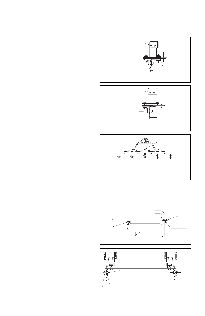
The full length of the fifth wheel mounting
angle should seat flush on the truck frame
when mounting to prevent flexing of
mounting angle and to give uniform
weight distribution along truck frame rail.
5/8” diameter Grade 8 bolts minimum size.
Tightening torque to bolt manufacturer charts.
Hardened steel washers or flanged locknuts.
5/8” diameter Grade “C” locknuts.
TRUCK FRAME RAIL
Stationary Fifth Wheel Installation continued
Bracket with Mounting Base
(See Figures 2A, 2B, and 2C):
1. Holland brackets with mounting
base are intended for installation
on either corrugated or flat
mounting plates.
continued
2. In addition to the information
given in “Installation: General
FIGURE 2A
Recommendations,” on page 3,
follow the recommendations in
FIGURES 2A, 2B, and 2C.
3.
See “Installation: General
Recommendations” on page 3
for angle thickness and material.
The mounting angle should be 1˝
longer than the mounting plate,
and be 36˝ minimum length.
FIGURE 2B
Use 3˝ minimum horizontal and
3 -1/2˝ minimum vertical leg size.
Longer horizontal legs may be
required with narrow frame widths.
FIGURE 2C
Sliding Fifth Wheel Installation
Prior to proceeding with the installation of the sliding fifth wheel assembly,
carefully review the “General Safety Information” section on page 2.
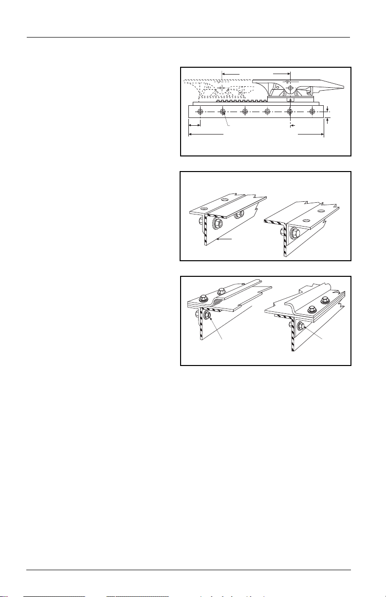
Inboard Angle Mounting
(See Figures 3 and 4):
1. Angles must be installed on the
sliding fifth wheel base plate to
facilitate mounting. See “Installation:
General Recommendations,” on page
3, for angle thickness and material.
FIGURE 3
2. Use a mounting angle which is at
least 2˝ longer than the slide base
plate and 36˝ minimum length.
Use 4˝ minimum horizontal and
3-1/2˝ minimum vertical leg size.
The fifth wheel top plate and support
bracket may be removed from the
base plate for ease of handling.
XL-FW503 Rev B 5
FIGURE 4 (End View)
INSTALLATION INSTRUCTIONS
1.00˝
(25.4 mm) MIN.
CENTER LINE OF
TRACTOR REAR
AXLE(S) OR
BOGIE
PLATE LENGTH PLUS 2.00˝ MIN. (50.8 mm)
4.00˝
(101.6 mm)
max.
1˝ min. 6 bolts equally spaced
FORWARD TRAVEL
TRUCK FRAME RAIL
The full length of the fifth wheel mounting angle should seat flush on
the truck frame when mounting to prevent flexing of mounting angle
and to give uniform weight distribution along truck frame rail.
5/8˝ diameter Grade 8 bolts minimum size,
tightening torque to bolt manufacturer charts.
Hardened steel washers or flanged locknuts.
5/8˝ diameter Grade “C” locknuts.
HARDENED STEEL
WASHERS
continued
Sliding Fifth Wheel Installation continued
Inboard Angle Mounting continued
3. Position the angles on the slide
plate for the required frame width.
Be sure to keep the plate centered
left to right, and front to rear on
the mounting angles.
4.
Weld as shown in FIGURE 3. Make
5/16˝fillet welds inside and 3/8˝
groove welds on the outside with skip
welds 3˝ long on approximately
8-1/2˝ centers (weld 3˝, skip
5-1/2˝). Weld inside opposite skips
on the outside. ALSO WELD: The
plate to the top of the angle at the
ends of the plate.
5. Attach the slider plate and
mounting angles to the tractor
using recommendations in
“General Recommendations”
and in FIGURE 4.
6. Reassemble the fifth wheel top
plate and bracket sub-assembly to
the slider base plate if they were
removed previously.
FIGURE 4 (Side View)
FIGURE 5
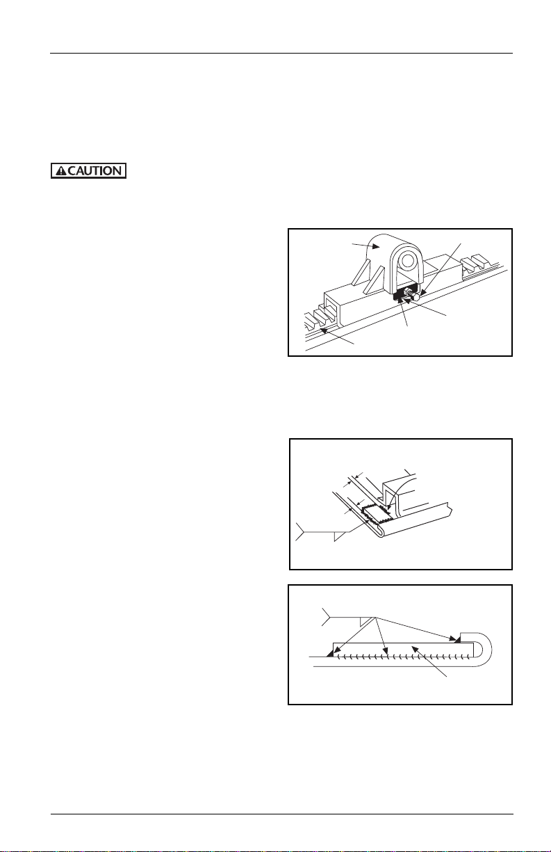
Outboard Angle Mounting
(See Figures 5 and 6):
1. If angles are not installed, see “Installation: General Recommendations,” on page 3,
for thickness and material. Use 3˝ minimum horizontal and 3-1/2˝ minimum
vertical leg size. Longer horizontal legs may be required with narrow frame widths.
The recommended length of each mounting plate is the same length as the slide
base mounting plate.
2. In addition to the information given in “Installation: General Recommendations,”
on page 3, follow the recommendations in FIGURE 5 and FIGURE 6. The following
sequence is suggested:
A. Securely position the mounting angles to the tractor frame and attach as shown
in FIGURE 5. Follow the bolting recommendations as shown in FIGURE 4. Angles
must be flush with the top of the truck frame.
B. Locate the slide base and center left to right and front to rear on the mounting
6 XL-FW503 Rev B
angles. Clamp in place and drill 21/32˝ diameter holes using the mounting
plate as a template if holes are not provided in the angle.
C. Align holes in the slide plate with outboard angle mounting holes and bolt
using Grade 8 fasteners, hardened steel washers and Grade C locknuts, properly
tightened, (see FIGURE 6). Use all mounting holes on the fifth wheel.
FIGURE 6
PLUNGER ADJ. BOLT
POCKET
PLUNGER
RACK
BRACKET CAP
1/8”
1/4”-1/2”
Locate and weld the
rear slide stops per steps
2 through 5 above.
Weld the forward side
in the center only
to avoid interference
with the bracket.
TYP.
5/16˝
Dimensions apply
after welding.
TYP.
5/16˝
SLIDE STOP
INSTALLATION INSTRUCTIONS
Sliding Fifth Wheel Installation continued
Adjustment of Sliding Bracket Locking Plungers
The slide locking plungers are given a preliminary adjustment during factory assembly.
However, due to variations introduced during mounting (such as frame and material
tolerances) a final adjustment must be made at the time of installation.
Adjust the locking plungers at installation, after one month of service,
and at recommended maintainence intervals. by use of the adjusting
bolts provided on both sides. Failure to do so may result in accelerated wear of
components, lower service life, improper load transfer, or improper load distribution.
To adjust locking plungers:
1. Loosen lock nut and turn adjusting bolt
out (counterclockwise). See FIGURE 7.
2. Disengage and engage the locking
plungers. Check that the plungers are
securely seated without binding.
3. Turn the adjusting bolt in (clockwise)
until it contacts the rack. Turn the bolt
an additional 1/2 turn then tighten the
locking nut securely.
Prior to proceeding with the installation of the sliding fifth wheel assembly, carefully
review the “General Safety Information” section on page 2.
Installation of Slide Stops
1. It is the responsibility of the installer
to insure that slide stops are installed
properly at all four corners of the
slider plate.
2. Slide the bracket to the full rear
position and engage the plungers in
the rack.
3. Locate rear stops under the curled
edge allowing some clearance to the
bracket (approximately 1/8˝). Clamp
in place. This should position the
stops approximately 1/4˝ to 1/2˝
from the edge of the rear of the plate,
see FIGURES 8A and 8B.
4. Slide bracket ahead out of the way
and weld the stops in place as shown
in FIGURES 8A and 8B. The welds
should be 5/16˝ fillet.
5. Slide the bracket to the full rear
position and check for clearance.
Make sure the plungers on the sliding
bracket seat properly into the rack
with all teeth engaged.
6. Repaint as required.
XL-FW503 Rev B 7
FIGURE 8A
FIGURE 8B (Rear End View)
continued
FIGURE 7
(Outside View)

INSTALLATION INSTRUCTIONS
continued
Attachment of Air-Activated Slide Release – If Required
1. Mount the cab control valve in accordance with the instructions provided. It should
be readily accessible to the driver, but protected to prevent accidental activation.
2. Attach an air line, using appropriate fittings to the “air” or “in” port of the valve.
Use an air source recommended by the tractor manufacturer. Use fittings and lines
of suitable pressure rating.
3. Connect an air line between the “cyl” or “out” port of the valve and the active side
of the air cylinder. A bulkhead fitting may be placed at the front of the slide base
plate, if desired. Use fittings and lines of suitable pressure rating and be sure line is
run so as not to interfere with any other operation or component.
4. Check operation of the valve and cylinder.
Inspection and Lubrication Prior to Use
1. Review the installation. Be sure all nuts and bolts are in place and properly
tightened. Be sure all necessary steps were properly followed and that all
components removed to facilitate installation are reinstalled.
2. Check the fifth wheel locking mechanism with a Holland TF-TLN-5001 (2˝) or
TF-TLN-1500 (3-1/2˝) Lock Tester. Examine for proper locking as described in the
“Operating Instructions” of this manual. This must be done to assure that the
mechanism has not been damaged by shipment, handling, or storage.
Failure to properly install, operate, or maintain this fifth wheel could
result in tractor and trailer separation causing death or serious injury
to others.
3. Apply grease to the bearing surface of the support bracket through the grease
fittings on the side or front of the fifth wheel pockets. The top plate must
be lifted up slightly to ensure proper application of grease. (NOTE: This is not
required on Holland LowLube and NoLube top plates.)
4. Apply a generous coating of grease to the top of the fifth wheel plate, where it will
contact the trailer plate. (NOTE: This is not required on Holland LowLube and
NoLube top plates.)
5. Apply a generous coating of grease to the front lock and lock jaws.
8 XL-FW503 Rev B

OPERATING INSTRUCTIONS
UNLOCK
NOTCH
LOCK NOTCH
1st
2nd
3rd
TILT
DOWNWARD
OPEN
“Ready to Couple”
CLOSED
Wheel is Locked!
DO NOT
Attempt to Couple!
Failure to properly install, operate, or maintain this
fifth wheel could result in tractor and trailer
separation, causing death or serious injury to others.
Fifth Wheel Inspections
1. Inspect the fifth wheel and mounting.
• Confirm that the lube plates
are in place and firmly attached.
• Tighten loose fasteners.
• Replace missing fasteners.
• Repair/replace missing, cracked or
otherwise damaged components.
2. Make sure the lock is open. To open the lock, pull secondary
lock handle and hook on casting, if equipped. Then pull
primary release handle, as shown.
3. Inspect the lock jsw; if it appears dry,
apply greawse to lock jaw and front of
throat directly, or throught the lube tube
grease fitting located near the front,
leftside of the fifth wheel.
4. Tilt the ramps down.
XL-FW503 Rev B 9
LUBE
TUBE

OPERATING INSTRUCTIONS
CHAMFERED (Preferred)
or LARGE RADIUSED
LEADING EDGE
20°
2˝
min.
40˝
6˝min.
6˝min.
Keep bolts and nuts
clear of this area
Keep path of fifth
wheel free of
large holes
& gouges
continued
Trailer Upper Coupler Inspections
1. Inspect the leading edge of the trailer
bolster/skid plate. It must be free of
any square or sharp edges.
2. Make sure there are no bolts or nuts
extending below the bolster/skid plate
within 6˝ of the fifth wheel travel path
while coupling.
3. The area that is supported by the fifth
wheel should be free of any large holes
or gouges.
4. Any access holes that the fifth wheel
passes below should have chamfered
or radius edges.
5. Check that any splits from the skid
plate to bolster plate are welded
adequately and that there are no
sharp edges or abrupt changes in
elevation.
6. The upper coupler should extend
adequately rearward to maintain full
contact with the fifth wheel during
tight turning. If it does not, at a
minimum, the rear edges should be
chamfered or radius edges.
7. Make sure that any upper coupler
residual grease is free of heavy coarse
grit.
8. Ensure that the upper coupler fifth
wheel contact surface is free of rust. Do
not paint the contact area! The area
should be conditioned with rust
inhibitor such as a light oil.
9. Inspect the kingpin for excessive wear
and damage (use Holland tool TF-0110
Kingpin Gage) along with bolster bow
(see SAE 1700).
10 XL-FW503 Rev B

OPERATING INSTRUCTIONS
TRAILER
(TOP)
KINGPIN
Coupling Procedures
1. Make sure the coupling area is flat,
level, and clear of persons and
obstacles.
2. Center the fifth wheel with the
kingpin and back up straight.
3. Back the tractor close to the
trailer and STOP.
continued
Back in and
STOP!
4.
Chock trailer wheels.
5. Connect brake lines and light cord.
6. Support slack in lines to prevent
interference.
7. Set trailer brakes.
Failure to properly install, operate, or maintain this
fifth wheel could result in tractor and trailer
separation, causing death or serious injury to others.
XL-FW503 Rev B 11

OPERATING INSTRUCTIONS
PULL FORWARD WITH TRACTOR
PULL TEST
SECURE
CRANK
NUT AND WASHER SNUG
AGAINST FIFTH WHEEL
LOCKS COMPLETELY
CLOSED AROUND
KINGPIN
NO GAP!
FIFTH WHEEL
MUST LIFT
TRAILER
à
FIFTH WHEEL
TILTED DOWN
4˝- 6˝
USE LOW
GEAR
continued
Coupling Procedures continued
8. Adjust trailer height so fifth wheel
will lift trailer. Trailer should
contact fifth wheel 4˝ - 6˝
behind fifth wheel bracket pin.
Attempting to couple
improper height could result in a false
or improper coupling.
9. Slowly back into trailer.
with the trailer at an
Do a pull test as an INITIAL CHECK.
10.
The coupling procedure
is not complete without
a visual inspection. Y
ou must get out of
the tractor and verify that the fifth wheel
is properly coupled to the kingpin as
shown below.
11. Visual inspection.
Get out of the tractor.
Visually check that the
lock is closed.
12 3
If you do not obtain a
proper couple, repeat
the coupling sequence. Do not use any
fifth wheel that fails to operate properly.
12. Retract landing gear until pads come
off the ground.
Switch to high gear, fully retract, and
13.
secure crank handle.
14. Check the brake lines and light cord.
Remove the wheel chocks and
USE
LOW
GEAR!
continue with a pre-trip inspection.
12 XL-FW503 Rev B
TRAILER
BRAKES
LOCKED

OPERATING INSTRUCTIONS
SECURE
CRANK
UNLOCK
NOTCH
LOCK NOTCH
1st
2nd
3rd
“READY TO
COUPLE”
POSITION.
WHEEL IS OPEN.
OUT
UP
PRIMARY
RELEASE HANDLE
SECONDARY
RELEASE HANDLE
Uncoupling Procedures
1. Position tractor and trailer on firm,
level ground clear of obstacles and
persons.
2. Set trailer brakes.
3. Slowly back tractor tightly against
trailer.
4. Set tractor brakes.
5. Chock trailer wheels.
6. Lower landing gear until pads just
touch the ground.
7. Switch to low gear
additional 4-8 turns.
8. Disconnect brake lines and light
cord. Attach brake line to dummy
coupling to keep line clean.
9. If equipped, pull secondary lock
handle and hook on casting (located
on left/road side of fifth wheel).
and crank an
USE
HIGH
GEAR
USE
LOW
GEAR
continued
10. Pull primary release handle.
11. Release tractor brakes and slowly
drive away from trailer. Let the
trailer slide down the fifth wheel
and pick-up ramps, being careful
that the trailer landing gear touch
theground with minimal impact.
NOTE: It is normal after uncoupling for
the release handle to come off the
unlock notch and move to a “ready to
couple” position.
XL-FW503 Rev B 13

UNLOCK LOCK
UNLOCK LOCK
OPERATING INSTRUCTIONS
continued
Fifth Wheel Slide Adjustment
1. Position tractor and trailer in a straight line on level ground.
2. Lock the trailer brakes.
The trailer must be stopped and the trailer brakes
locked to prevent damage to the tractor or trailer
by uncontrolled sliding of the fifth wheel.
3. Release slide locking
plungers.
Visually check that both
4.
plungers are fully extended,
as shown in Figure 4A.
NOTE: If the plungers do not
r
elease, using low gear on the
landing gear, raise the trailer
to relieve pressure on the
plungers. This will allow the
fifth wheel to slide easier.
5. Slowly drive the tractor forward or backward to position
the fifth wheel.
6. Re-engage the slide
locking plungers.
Verify that both
plungers have fully
engaged.
AIR OPERATED
Move cab switch
to unlock position.
FIGURE 4A
AIR OPERATED MANUAL SLIDE
MANUAL SLIDE
Pull release lever
lift up and hook in place.
FIGURE 4B
,
NOTE: Retract landing
gear if lowered.
14 XL-FW503 Rev B
Do not operate the vehicle if the plungers are not fully
engaged and landing gear fully retracted, as damage
to the tractor
Move cab switch
to lock position.
, trailer and landing gear may occur.
Trip the release lever by tapping
it downward as shown and
allowing it to spring back.

MAINTENANCE PROCEDURES
You must read and understand the following instructions before operating your
in these instructions may result in a hazardous condition or cause a hazardous condition to develop.
All maintenance must be performed by a qualified person using proper tools and safe procedures.
All maintenance must be performed while the tractor is uncoupled from the trailer.
fifth wheel. Failure to follow all of the important maintenance procedures contained
As-Needed and Periodic Lubrication
1. IMPORTANT! Always maintain adequate lubrication in fifth wheel locking mechanism.
Relube as necessary (see Figure 1).
2. Keep a low temperature, water resistant lithium grease applied to the trailer contact
surface of the fifth wheel.
CLEAN/
LUBRICATE
Cam bolt
Release arm bolt
Plunger-to-wedge
contact areas
Clean with spray
WD-40 or CRC
Lubricate with SAE
10W or 20W motor oil
WEDGE
Figure 1
PLUNGER
Lubricate
between parts
GREASE
Release handle
(See Step 5)
Bracket pocket fittings
(right and left sides)
Swing lock-to-cam arm
contact area
Recommended Greases
A “low temp” grade
recommended for -30°F or
lower such as:
Cato Oil & Grease #5213
Craftsman Chemical Co. #LTF 2
Mystic LP-200
or equivalent
3. Grease the support bracket pockets through the
grease fittings on the front of the fifth wheel
bracket pockets (lift up slightly on the fifth
wheel plate when applying grease).
4. For fifth wheels with sliding brackets:
Release and slide fore and aft to assure entire
mechanism functions properly
. Apply an aerosol
spray lubricant or soap to the slide path. Apply
Right Hand Release with Sliding Spring
Figure 1a
(Grease Required)
Never-Seez™to the plunger and its moving parts.
Reposition and lock sliding mechanism.
5. Inspect the release handle. If your fifth wheel is
a RIGHT HAND (curb side) release, apply grease
along the release handle where it contacts the
handle spring (see Figure 1a). If you have a LEFT
HAND (driver side) release handle with a sliding
spring, as shown in Figure 1b, apply grease
Left Hand Release with Sliding Spring
Figure 1b
(Grease Required)
along the release handle where it contacts the
handle spring. Lubrication is NOT required for
LEFT HAND (driver side) release handles that
HAVE a fixed spring (see Figure 1c).
6
. Check the operation by locking and unlocking
using a Holland TF-TLN-5001 Lock Adjustment
Tool. Verify that the fifth wheel is completely
closed, as shown in Figure 3A on page 14.
Left Hand Release with Fixed Spring
Figure 1c
(No Grease Required)
XL-FW503 Rev B 15

MAINTENANCE PROCEDURES
PLUNGER
LOCK JAW
AROUND KINGPIN
PLUNGER VISIBLE
AS SHOWN
TRAILER
BOLSTER PLATE
KINGPIN
LOCK
NOTCH
BEHIND
RIB
CLOSED POSITION
continued
Do not use any fifth wheel
that does not operate
properly
operate properly, contact your nearest
Holland representative for assistance.
Failure to properly operate this fifth wheel
could result in tractor and trailer separation
and may cause injury or death to others.
. If your fifth wheel does not
Required Inspections and
Adjustments
Perform the following every six months
or 60,000 miles, whichever comes first.
Thoroughly steam clean all components
before inspecting or adjusting.
General Fifth Wheel Inspection:
1. Inspect the fifth wheel mounting.
Check torque and replace any missing
or damaged bolts. Check for broken,
worn or damaged parts, replace as
needed.
2. Thoroughly clean the fifth wheel
locking mechanism every 6 months or
60,000 miles and relubricate (see
Figure 1 on page 15). Re-check
operation with TF-TLN-5001 Lock
Adjustment T
3. Inspect the fifth wheel for bent, worn
or broken parts. Replace with Holland
parts only.
4. Make sure the bracket pin retention
bolts and locknuts are in place and
, as shown in Figure 2.
tight
ool.
Inspection – Locking Mechanism
1. Check the operation of the fifth wheel
locking mechanism using a Holland
TF-TLN-5001 (2” kingpin) Lock
Adjustment Tool. Inspect for proper
locking as described in the “Fifth
Wheel Operating Instructions” section of
this manual.
2. IMPORTANT! The lock is properly
closed when:
Figure 3A
RIGHT!
Figure 3B
WRONG!
Figure 3C
Figure 2
Make sure bolt and
nut are in place and
tight (both sides).
16 XL-FW503 Rev B
Left Hand Release Shown

MAINTENANCE PROCEDURES
2
ROTATE
1
TIGHTEN
continued
Adjustment – Locking Mechanism:
1. Using ONLY a Holland TF-TLN-5001
Lock Adjustment Tool, lock the fifth
wheel.
2. Check the plunger – it must be
visible behind the lock and
engaged on both
Figure 3A. If the plunger is not visible
or not engaged on both steps (Figure
3B), turn the adjustment bolt
counterclockwise 1/2 tur
lock the locks again.
Figure 4
3. Check the release handle – it must
be fully retracted and the handle lock
notch must be behind the rib as
shown in Figure 3C.
Using a 15/16” socket, tighten the
4.
locks by turning the lock adjustment
bolt clockwise 1/4 turn at a time.
Remove the socket wrench from the
bolt and rotate the lock adjustment
tool, as shown in Figure 4, to check for
resistance between the lock and lock
adjustment tool.
Continue to alternate tightening
5.
(clockwise) the adjustment bolt 1/4
turn at a time, removing the socket
wrench, and rotating the lock
adjustment tool until you feel
resistance against the lock adjustment
tool. Once you begin to feel resistance,
STOP!
steps, as shown in
n, then try to
At this point, the fifth
and NOT useable. Using an improperly
adjusted fifth wheel could result in
tractor and trailer separation and may
cause injur
6. Loosen the adjustment bolt counterclockwise TWO FULL TURNS. The lock
is now properly adjusted.
Verify this adjustment by locking and
7.
unlocking several times using the Lock
Adjustment Tool; check for proper
locking (See Figure 3A and Figure 3C).
If there is a large amount of fore and
8.
aft movement with the adjustment
tool when verifying adjustment, check
to make sure the lock is engaged in
steps (Figure 2).
both
If the lock is only engaged on one
step, repeat Step 2 (above), of the
Adjustment Procedure until the lock
engages on both steps. (See Figure 3A.)
of the fifth wheel which could result in
tractor and trailer separation and may
cause injur
fifth wheel does not operate properly,
DO NOT USE IT! Repeat the adjustment
procedures or contact your local Holland
representative for assistance.
wheel is OVERADJUSTED
y or death to others.
Improper adjustment can
cause improper locking
y or death to others. If the
XL-FW503 Rev B 17

MAINTENANCE PROCEDURES
1/16”
CHECK FOR POSSIBLE
INTERFERENCE
continued
Adjustment – Fifth Wheel Slide
Mechanism
1. Loosen lock nut and turn adjustment
bolt out (counter-clockwise).
RACK
ADJUSTMENT
BOLT
LOCK NUT
2. Disengage and engage the locking
plungers. Verify that plungers have
seated properly as shown.
RACK
LOCKED
(ENGAGED)
3. Now tighten adjustment bolt until it
contacts the rack.
4. Turn the adjustment bolt clockwise an
additional 1/2 turn, then tighten the
lock nut securely.
5. If plungers do not release fully to
allow fifth wheel to slide:
a. Check the air cylinder for proper
operation. Replace if necessary.
b. Check plunger adjustment, as
explained above.
c. If a plunger is binding on the
plunger pocket, remove the plunger
using a Holland TF-TLN-2500
spring compressor. Grind the top
edges of the plunger 1/16˝ as
shown. Re-install and adjust the
plungers, as explained above.
RACK
Proper adjustment of the
formed at regular intervals and is
per
required for proper operatiion, load
transfer and distribution.
6. If the locking plungers are too loose:
a. Check plunger adjustment, as
explained above.
b. Check plunger springs for proper
compression. Replace if necessary.
c. Check for plunger wear. If
necessary, replace, as described
above.
After inspection and adjustment, relubricate
all moving parts with a light, rust resistant
oil.
locking plungers must be
UNLOCKED
(RELEASED)
18 XL-FW503 Rev B

))))))))))))))))
MANUAL SLIDING SECONDARY LOCK
Operating and Rebuilding Procedures
You must read and understand the standard FleetMaster operating instructions, along
with the following in the case where you have the manual sliding secondary lock. This
piece of literature is meant to be used in conjunction with Holland rebuilding literature
number XL-FW355-XX.
LEFT HAND
(ROAD SIDE)
RELEASE
➍
➏
11
MANUAL
➌
➋
➎
➒
➓
➐
➑
➊
SLIDING
SECONDAR
LOCK
Y
Item Part No. Description
1 XA-1674 Arm S/A Safety Release
2 XB-NRJ-34-F Nut Jam 3/4˝-16
3 XA-10216 Bar Tertiary Locking
4 XA-10213-2 Spacer Cover Plate
5 XA-10213-1 Spacer Cover Plate
6 XA-10212 Plate Cover
Manual Secondary Operation
Uncoupling
If equipped with a sliding secondary
lock, disregard use of rotating arm
secondary lock in Uncoupling Procedure
on page 11.
Follow this in its place:
1. Pull manual sliding secondary lock
handle out to the detent positions
(Figure 1).
Item Part No. Description
7 XB-T-49 Washer, 1/2˝
8 XB-T-45-1 Lock washer, 1/2˝
9 XB-10620 HHCS, 1/2˝-13 x 2-3/4˝
10 XB-3545 Clip, Hitch Pin
11 XA-10215 Guide S/A Tertiary Handle
Coupling
1. After following standard coupling
procedure, push manual sliding
secondary lock handle into lock
detent position (Figure 2).
Figure 1 Figure 2
XL-FW503 Rev B 19

MANUAL SLIDING SECONDARY LOCK
Rebuilding Instructions
Position cover on spacers and use
If your fifth wheel is equipped with the
manual sliding secondary lock, then
rebuild per standard FleetMaster
Rebuilding Instructions (XL-FW355-XX),
but replace the Manual Secondary Lock
Installation (as stated on Page 7 of
XL-FW355-XX) with the following:
Note: During assembly, use threadlocker
malok MM118, Loctite No. 243, or
(Per
equivalent on all threads.
1. Insert handle through guide subassembly and install jam nut on
handle rod (Figure 3 – Items 1, 2 & 11).
➁
Figure 3
Screw handle into threaded safety
2.
bar making sure handle grip is
oriented towards ramps of wheel and
tighten jam nut (Figure 4 & Figure 5)
(Item 3).
11
➊
➂
4.
two 1/2˝ washer, two 1/2˝ lock
washer, and two 1/2˝ x 2-3/4˝ bolts,
to fasten cover to casting (Figure 7)
(Items 6, 7, 8, & 9). Tighten fasteners.
Figure 7
➏
➒
➐
➇
5.
Pull secondary lock handle out so
that detent on handle is between
casting rib and guide tube (Figure 8).
Figure 8
Install spring clip on handle (Figure
6.
9) (Item 10).
Figur
Rib
Detent
e 9
➓
Figure 4 Figure 5
3. Position spacer tubes over threaded
holes in casting. These spacers come
in two different lengths, so be sure to
place shorter spaced on the raised
portion of casting (Figure 6) (Items 4
& 5).
Figure 6
➍
Long Spacer
Raised
Short Spacer
20 XL-FW503 Rev B
➎
Portion
7. Check the manual sliding secondary
lock for proper operation by
pulling/pushing handle to engage
secondar
should engage detent when
secondary locking bar is behind
primary lock and also engage detent
when pulled out to allow
uncoupling.
y locking bar. Handle

XL-FW503 Rev B 21

22 XL-FW503 Rev B

HOLLAND FW8 SERIES FIFTH WHEEL
NORTH AMERICAN COMMERCIAL WARRANTY
SAF-HOLLAND’s Commitment:
We warrant each FW8 and FW83 (LowLube model) fifth wheel
(herein referred to as “FW8 Series”) manufactured after August
1, 2003, when properly installed on your vehicle and maintained
in accordance with our requirements, as follows:
I. Materials and Workmanship:
Our FW8 Series fifth wheels will be free from defects in
material and workmanship for five years or 500,000 miles
(whichever comes first) when used for approved applications.
In approved applications, lube plates (FW83 LowLube model)
are warranted for two years or 200,000 miles (whichever
comes first).
II. Application Specific Performance
Guarantee:
In addition, when your FW8 Series fifth wheel is used in
Standard Duty Applications (as defined below) it will, for five
years after the date of your purchase or 500,000 miles
(whichever comes first):
1. Operate as described in our FW8 Series operation
and maintenance literature;
2. Maintain an acceptable wear limit between the fifth
wheel locks and a new SAE J700b kingpin when
adjusted in accordance with our FW8 Series
maintenance literature.
Standard Duty Applications require that your vehicle:
1) operates on-highway only; 2) has a maximum gross
combined vehicle weight of 95,000 lbs. (including tractor,
trailer and cargo); and 3) has a maximum of five axles.
If any FW8 Series fifth wheel or component part is determined
to have a defect in material and workmanship or if it does not
perform as warranted in a Standard Duty Application, we will
cover the cost to repair or replace the product or part. We will
provide a reasonable labor allowance for removal, and repair
or replacement, and will provide you with parts or reimburse
you for parts at your acquisition cost, provided this does not
exceed the suggested list price.
Your Responsibilities:
You are responsible for proper installation,operation and
maintenance (including lubrication) as specified in our
publications on FW8 Series fifth wheels and for using the
product in recommended applications within rated capacities.
You are required to obtain prior authorization from us or an
authorized customer service representative before replacing or
returning any part. You may be required to make the product or
part claimed to be covered by this warranty available to us
and/or returned to us for review and evaluation.
You may also be required to provide any or all of the following
information: vehicle mileage and VIN #,product model # and
serial # as shown on the serial tag installed on the product, date
of purchase, and application and use information.
Exclusions and Limitations:
This warranty does not cover any FW8 Series fifth wheel or
component that fails, malfunctions or is damaged as a result of
accident, abuse, improper use, improper installation, intentional
modification, corrosion, or failure to provide
reasonable maintenance.
THIS WARRANTY IS OUR SOLE WARRANTY IN REGARD TO
COVERED FW8 SERIES FIFTH WHEELS. WE MAKE NO OTHER
WARRANTIES, EXPRESS OR IMPLIED, OR OF
MERCHANTABILITY OR FITNESS FOR A PARTICULAR
PURPOSE. IN NO EVENT SHALL WE BE RESPONSIBLE FOR
SPECIAL, INCIDENTAL, OR CONSEQUENTIAL DAMAGES OF
ANY KIND.
XL-WC102-04 Rev C
Copyright © 2008 • SAF-HOLLAND, Inc.
WARRANTY
XL-FW503 Rev B 23

IMPORTANT: Enclosed is important
information for the installation, operation,
and maintenance of this product. Read and
understand this information.
WARNING
FAILURE TO PROPERLY INSTALL, OPERATE, OR
MAINTAIN THIS FIFTH WHEEL COULD RESULT IN
TRACTOR AND TRAILER SEPARATION CAUSING
DEATH OR SERIOUS INJURY TO OTHERS.
CAUTION
OPEN CLOSED
Holland FleetMaster locks are shipped closed from the factory. Open the
locks before using. Failure to open locks can result in damage to the pin.
TO OPEN LOCKS: Slide the handle forward and pull it out to the
maximum extension. The lock will swing to the open position.
SAF-HOLLAND USA, Inc. SAF-HOLLAND Canada Limited
888.396.6501 Fax 800.356.3929 519.537.3494 Fax 800.565.7753
Copyright © July 2008-SAF-HOLLAND, Inc. All information contained in this document was correct at time of copyright, and is subject to change without notice. All rights reserved.
24 XL-FW503 Rev B
www.safholland.us
Western Canada
604.574.7491
Fax 604.574.0244
 Loading...