

FIFTH WHEEL
OWNER’S
MANUAL
FW2800 and FW2900 Series
Hydraulic Elevating
Fifth Wheel
Installation, Operation,
Maintenance Procedures and
Comprehensive Warranty
TECHNOLOGY
XL-FW488 Rev A
Questions or Comments?
Call
www.thehollandgroupinc.com
FIFTH WHEELS
1-888-396-6501
INSTALLATION INSTRUCTIONS
When welding, use a procedure which assures a sound, good quality
cause distortion and damage, and underwelding may not develop sufficient strangth. A
low hydrogen process and AWS E70XX filler metal are recommended. Take precautions
to ensure that the tractor electrical system is not damaged by the welding.
weld and which protects the operator and others. Overwelding may
Fifth Wheel Design and Intended Use:
1. For pulling trailers with standard SAE kingpins which are in good condition and
securely mounted or locked in position in the trailer.
2. Within the capacities stated in Holland literature.
3. As recommended in Holland literature (available from Holland or Holland distributors).
Holland Fifth Wheels are NOT Designed or Intended For:
1. Use with non-SAE kingpins, such as kingpins which are bent, improper size or
dimension, not secured to maintain SAE configuration, or which are installed in
warped trailer bolster plates.
2. Tow-away operations which damage or interfere with the proper operation of the
fifth wheel.
3. The transport of loads in excess of rated capacity.
4. Applications other than recommended.
Installation
General Recommendations
1. Every user and installer using Holland products either recommended or not
recommended by Holland, must ensure that the installation procedure used is
appropriate for the vehicle, product and application.
2. Consult the Holland literature for fifth wheel capacities and applications.
3. Determine the range of proper fifth wheel positions. Proper positioning of the fifth
wheel is important for weight distribution, swing clearance and handling characteristics.
The center of the kingpin locks must always be positioned on or
ahead of the tractor rear axle or bogie centerline. Failure to do so
can result in loss of vehicle control.
4. Use Grade 8, 5/8˝ minimum diameter bolts and Grade “C” locknuts for mounting.
5. Bolt holes can be 1/32˝ larger in diameter than the bolt fastener. Bolts must be
adequately tightened using charted torque ranges in foot-pounds for the
recommended Grade 8, 5/8˝ diameter bolts. Larger diameter Grade 8 bolts and
coated fasteners may be used.
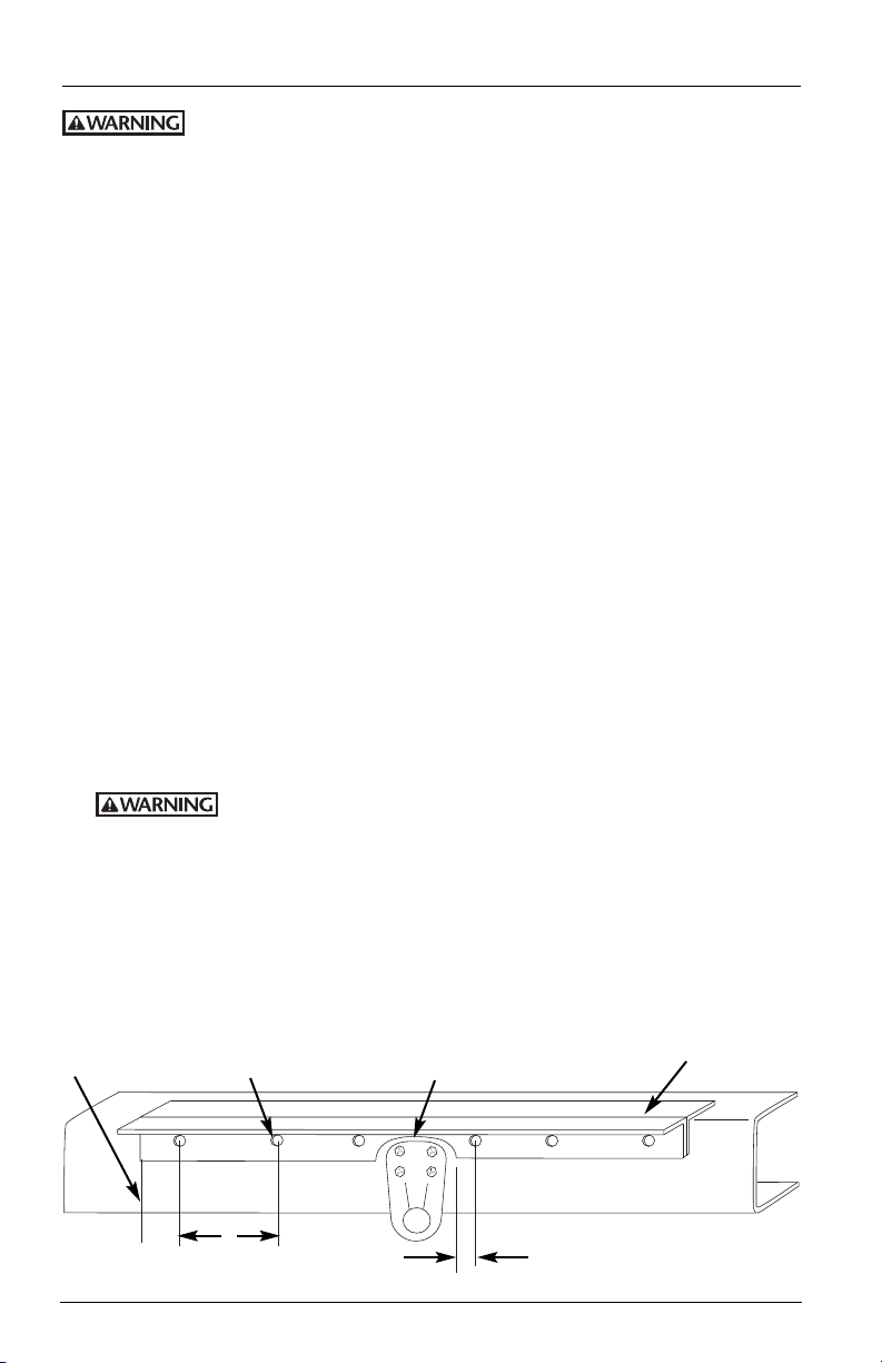
Figure 1
1˝ min. from
hole to the end
of the angle.
Holes drilled for
5/8˝ mounting
bolts.
Angle cut out for tractor
frame interference. 1˝
minimum for radius.
Lift wheel
mounting base.
1
⁄2˝ mounting required
8˝
Maximum
hole spacing
2
1˝ – 1
between 1˝ and 11⁄2˝ of
angle cut out.
XL-FW488 Rev A
INSTALLATION INSTRUCTIONS
APPROX. 1˝ APPROX. 1˝
FIFTH WHEEL MOUNTING FRAME
MOUNTING ANGLE MARK ANGLES HERE
PIVOT LOCATION
continued
6. The bolts attaching the fifth wheel mounting angles to the truck frame require
hardened steel washers under both the bolt and under the locknut, unless flanged
head bolts or flanged head locknuts are employed.
7. A minimum of 5 bolts should be applied to attach each mounting angle to the
tractor frame rail, and the distance between bolts should not exceed 8˝, except
when cutouts are required in the mounting angles (see Figure 1).
8. Whenever a cutout is made on the mounting angle, such as required to bypass
spring hangers, a 1˝ minimum radius should be used and bolts should be placed
within 1-1/2˝, but not closer than 1˝ of the cut, fore and aft (see Figure 1).
9. When initially positioning the fifth wheel for frame holes, the full length of the fifth
wheel mounting angles should seat flush on the top and side surfaces of the trucktractor frame rails where channel-type rails are employed. There should not be a
gap over the top of the truck frame rails. The base of the fifth wheel assembly and
of the mounting angle members should seat flush on the top of the frame rail to
prevent flexing and to give uniform weight distribution. It is also recommended to
chamfer or smooth any sharp edges and corners of mounting materials wherever
contact is made with the tractor frame.
10. Review “System Check” found on page 8.
Detailed Information
1. Remove the shipping lugs
from the bottom of the unit.
2. Determine the proper fifth
wheel position on the tractor:
A. Verify that the tractor has
sufficient “Cab to Axle”
(C.A.) clearance for the
elevating fifth wheel
model selected, as listed
Chart 1 and Figure 2.
in
B. Locate the pivot point of
the fifth wheel (when it’s
in the down position) on
the given mounting
angles by positioning the
angles approximately 1˝
beyond each end of the
fifth wheel assembly
frame. Once this has been
completed, mark the pivot
point of the fifth wheel on
both angles (see Figure 3).
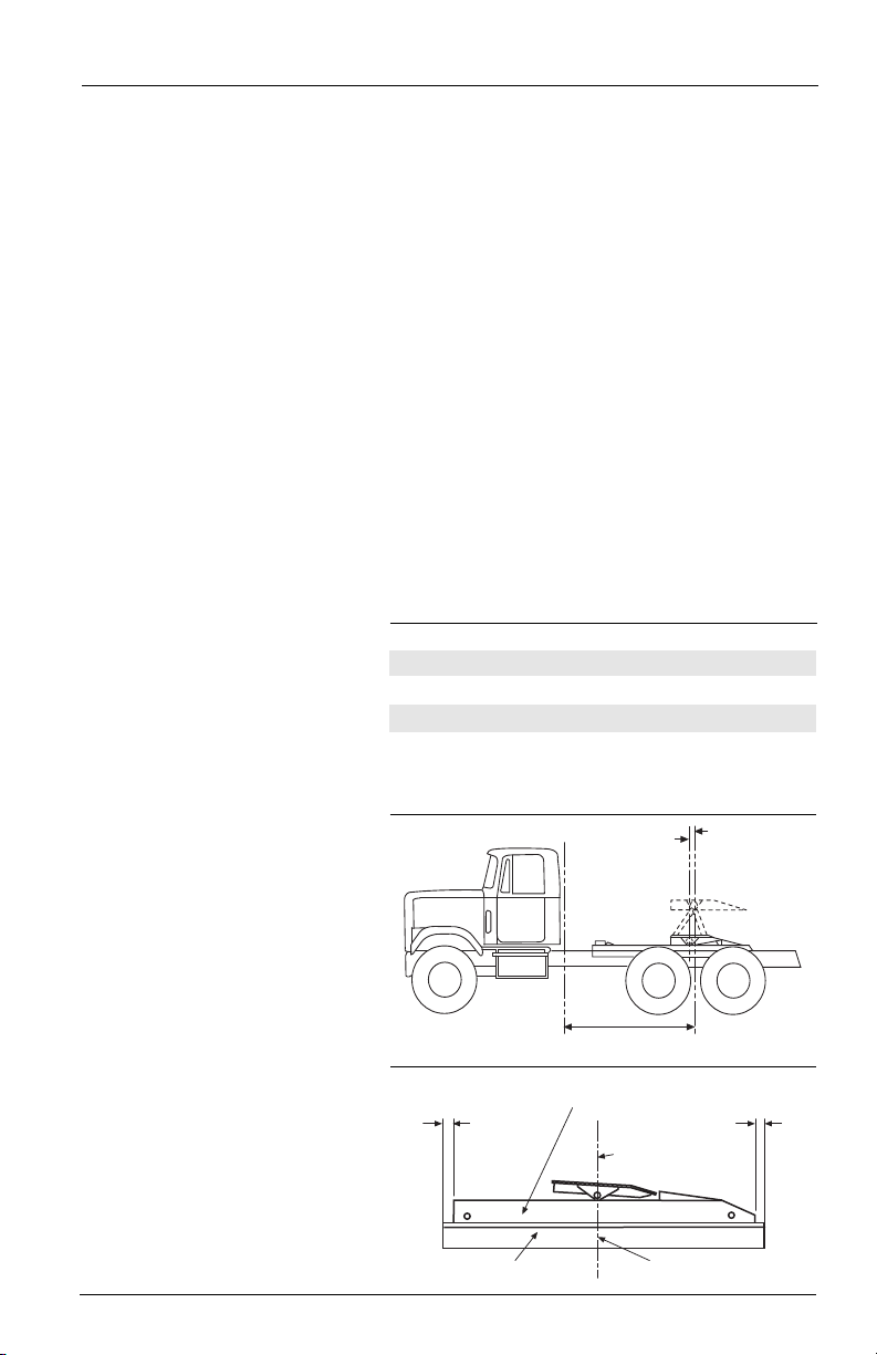
Chart 1
Cab to Axle Requirements and Mounting Location
MODEL CAB TO AXLE* LOCATION (A)
MINIMUM MOUNTING
FW2800-X 72˝ 10˝
FW2800-5X 77˝ 10˝
FW2900-X 60˝ 6˝
FW2900-5X 65˝ 7˝
* Based on a 102˝ wide, square corner trailer, with a 36˝
kingpin setting. More or less cab to axle clearance may be
required for other nose configurations, kingpin settings,
refrigeration units, etc.
Figure 2
(A)
FIFTH WHEEL
MOUNTING
LOCATION
CAB TO AXLE
CLEARANCE
CENTERLINE
OF THE REAR
AXLE/BOGIE
Figure 3
XL-FW488 Rev A
3
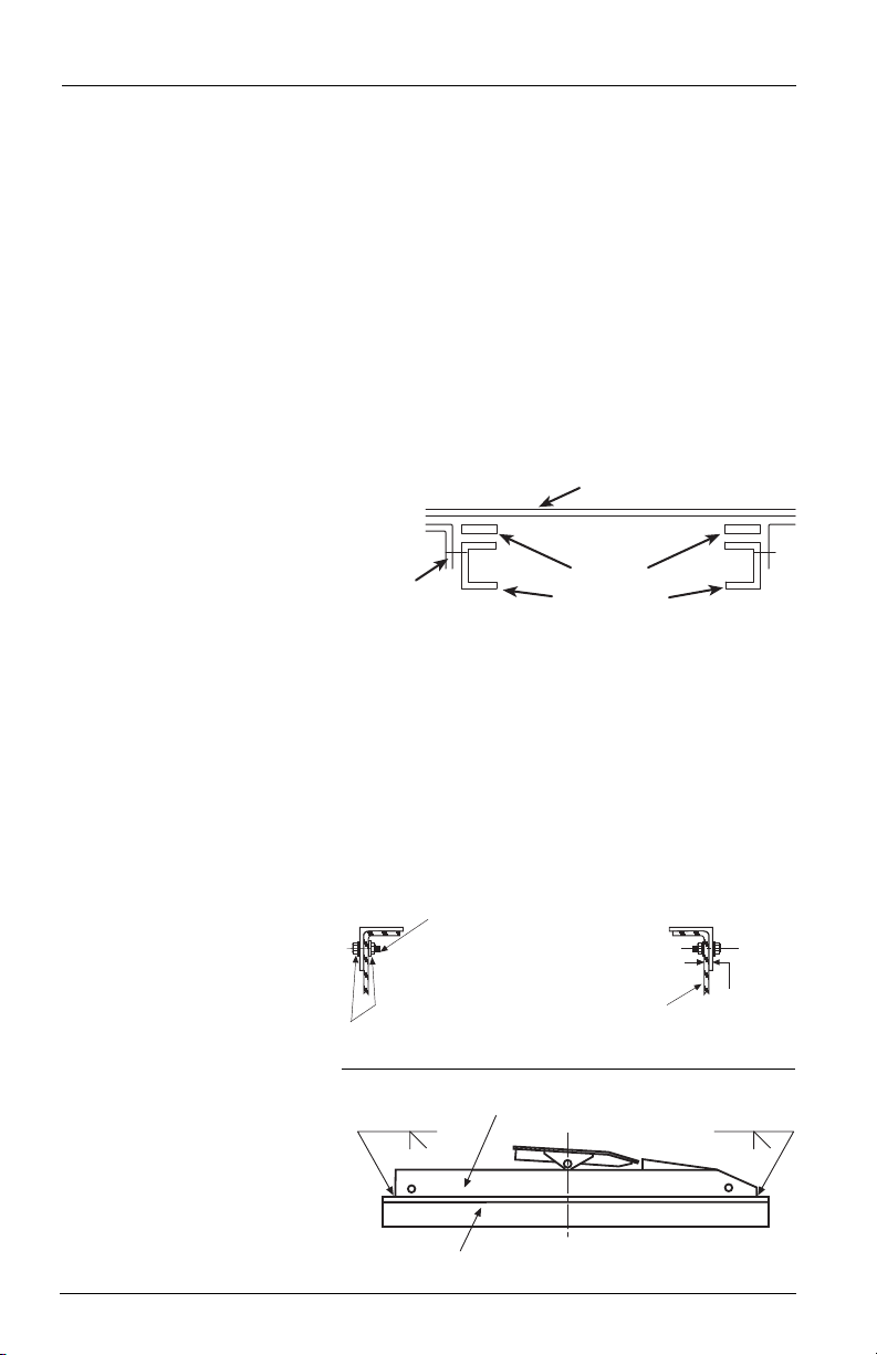
INSTALLATION INSTRUCTIONS
5˝x 5˝
ANGLE
SPACER
FRAME RAILS
FIFTH WHEEL MOUNTING FRAME
TRUCK
FRAME
RAIL
3/8˝
(9.53mm)
MINIMUM
ANGLE
HARDENED
STEEL WASHERS
The full length of the fifth wheel mounting angle should
seat flush on the truck frame when mounting to prevent
flexing of mounting angle and to give uniform weight
distribution along truck frame rail.
.63” diameter Grade 8 bolts
minimum size.
Tightening torque to bolt
manufacturer charts.
Hardened steel washers or
flanged locknuts. .63”
diameter Grade “C” locknuts.
3/8˝ 3/8˝
FIFTH WHEEL MOUNTING FRAME
MOUNTING ANGLE
continued
C. Take the marked angles and position them on the tractor frame.
NOTE: The marked angles will no longer be symmetrical. It is critical
to make certain that the angles are notaccidentally reversed.
D. Line up the marks of both angles with the imaginary centerline of the rear
axle/bogie. Use the dimension listed under “Mounting Location (A)” in Chart 1
for the elevating fifth wheel model selected, and offset the angle forward (toward
the cab) by that distance.
NOTE: The offsetting of the angles is necessary to allow for the horizontal (forward)
movement of the wheel when elevating. When the wheel is in its maximum vertical
condition, the pivot point of the wheel will be in line with the imaginary centerline
of the rear axle/bogie and the centerline markings made on the angles in Step 2B,
above (see Figure 2).
3. Once the proper position of the angles is known, mark the angles in all areas of
interference between the angles and the tractor frame. For example, mark the areas
of the angle needed to be cut out to clear bolts, rivets, spring hangers, etc.
NOTE: A spacer may be
required to obtain
Figure 4
clearance between the
hydraulic cylinder (and
hoses) and the
transmission or cross
members. If a riser is
needed, it may be
necessary to use 5˝x 5˝
angles.
4. Remove the angles from the tractor frame and machine any interference areas in
accordance with the “
Installation: General Recommendations” found on the page 2.
5. Clamp the mounting angles tightly to the tractor frame. Be certain to check
clearances of cutouts. Drill holes in accordance with the “Installation: General
Recommendations” found on the page 2.
6. Remove the clamps and fasten the angles, in accordance with the “General
Information”. In addition, see Figure 5.
7. Position the fifth wheel
Figure 5
on the mounting angles
with the top plate pivot
on the marked location.
Verify that there are no
interferences and that
the fifth wheel frame
seats flush on the
mounting angles. Tack
weld the fifth wheel to
the mounting angles.
8. Weld the ends of the
fifth wheel assembly
frame to the top of the
mounting angles with
two 3/8˝ groove welds,
as shown in Figure 6.
4
Figure 6
XL-FW488 Rev A

INSTALLATION INSTRUCTIONS
5/16˝
3-8
1
/2˝
3/8˝
3-8
1
/2˝
FIFTH WHEEL
MOUNTING FRAME
MOUNTING ANGLE
continued
9. Remove the rear pivot shaft (see corresponding fifth wheel’s parts list — pages 11
through 12 — in combination with Chart 2 — to find the rear pivot shaft):
Chart 2
Rear Pivot Shaft Identification
FIFTH WHEEL REAR PIVOT SHAFT REAR PIVOT SHAFT
PART NUMBER PART NUMBER DETAIL NUMBER
FW2800-X XA-2895 Detail #7
FW2900-X XA-2895 Detail #7
FW2800-5X XA-2895 Detail #37
FW2900-5X XA-2895 Detail #37
10. Using a lifting device, pick up the rear support assembly (see corresponding fifth
wheel parts list in combination with Chart 3 to find the rear support assembly). For
safety, block out the assembly after it is lifted.
Chart 3
Rear Support Assembly Identification
FIFTH WHEEL ASSEMBLY ASSEMBLY
PART NUMBER PART NUMBER DETAIL NUMBER
FW2800-X XA-2808-B Detail #2
FW2900-X XA-2908-B Detail #2
FW2800-5X XA-2808-B Detail #32
FW2900-5X XA-2908-B Detail #32
11. Use air pressure to extend the cylinder rod(s) approximately 12˝. Be sure to cover
the cylinder rod(s) to protect from weld splatter.
12. Weld the fifth wheel frame to the mounting angles per
skip welds inside the frame, and 3/8˝ groove skip welds on the outside. Make the
skip welds 3˝ long on approximately 8-1/2˝ centers (i.e. weld 3˝ bead, skip 5-1/2˝).
Make inside skip welds opposite to the outside welds.
REAR SUPPORT REAR SUPPORT
Figure 7. Make 5/16˝ fillet
Figure 7
13. Reassemble the rear pivot shaft removed in Step 9.
XL-FW488 Rev A
5

POWER TAKE OFF (PTO) AND
HYDRAULIC PUMP INSTALLATION
General Information
1. Hydraulic fifth wheels require certain hydraulic components for operation. These
components should have the following characteristics:
A. Pump – Single cylinder, 17 gallon/minute @ 1300 r.p.m.
B. Power Take Off – Compatible with transmission and pump, and with an
output as close as possible to engine speed (i.e. 1-to-1 ratio).
C. Hose and Fittings – Should be of good quality and selected to handle the
maximum pump output at 2,000 p.s.i.
Hydraulic Oil – Selection of the proper oil is a prime requirement for
D.
satisfactory system performance and life.
Detailed Information
1. Install the PTO in accordance with the PTO manufacturer’s instructions. In the
absence of instructions, proceed as follows:
A. Start the tractor and listen to the transmission. After installation, the
transmission should sound similar.
B. Shut off the tractor and drain the transmission fluid.
C. Remove the transmission cover plate from the PTO installation point.
D. Check the PTO and transmission gears for proper width, diameter, and
location.
E. Install studs in the transmission.
F. Install gaskets and sufficient shims on the transmission.
G. Install the PTO. Draw the nuts evenly while checking the gear backlash. When
fully tightened, the backlash should be .008˝– .012˝. If the backlash is
incorrect, remove the PTO and add or remove the required shims.
H. Check for free shifting. If free, refill the transmission to the proper level.
I. Install the PTO shift controls.
J. Start the tractor. Engage the PTO and listen to the transmission. If any
unusual noises occur, inspect and correct using the shimming procedure
outlined above in Step F.
2. Install the hydraulic pump per the manufacturer’s recommendations.
Hydraulic Component Installation
1. Install the oil tank and brackets. The tank should be located as close to the pump
as possible, with the bottom of the tank higher than the inlet port on the pump.
2. Install the hydraulic control valve.
A. Manual – Locate the valve in the cab at a convenient operation location.
Then, route the hydraulic hoses through the cab to the pump, tank, and
manifold.
B. Air Operated – If your unit was purchased with the optional air operated
control valve kit (RK-2800-50), install as follows (refer to FIGURE 8 for the
following steps):
1. Mount the control valve/air cylinder assembly in a convenient location,
between the manifold and air valve.
2. Mount the lift control valve in the cab in a location were it will not be
accidentally activated.
3. With hoses, connect the air supply from a location recommended by the
chassis manufacturer.
6
XL-FW488 Rev A

POWER TAKE OFF (PTO) AND
LIFT CONTROL VALVE
FROM
TRACTOR
AIR SUPPLY
HYDRAULIC MANIFOLD
ADJUSTABLE
COUPLING
CONTROL VALVE/AIR CYLINDER ASSEMBLY
HYDRAULIC PUMP INSTALLATION
Hydraulic Component Installation continued
NOTE: Hose and fittings for these connections are to be supplied by the
customer/installer.
4. Connect the air lines from the lift control valve to the control valve/air
cylinder.
5. Connect the hydraulic hoses from the hydraulic valve to the hydraulic
manifold.
6. Operate the air lift control valve in both the up and down position, and
inspect the hydraulic control valve. In either position, the hydraulic
control valve must be fully actuated. If not, adjust the coupling until full
stroke is achieved (see
Figure 8
Figure 8.)
continued
3. Install all hydraulic hoses and fittings (as shown in the piping diagrams on pages
9 and 10) for the model selected. Use care to assure that all hoses and fittings are
clear and free from foreign material and that all joints are properly sealed.
4. Fill and bleed the hydraulic system.
A. Have, on hand, sufficient hydraulic oil for the model selected. The
approximate system volumes are given below:
MODEL: SYSTEM VOLUME
FW2800-X 71/2gallons
FW2800-5X 12 gallons
FW2900-X 6 gallons
FW2900-5X 91/2gallons
NOTE: These volumes ar
installation to installation. They ar
approximately 2-1/2 gallons reserve in the oil tank when the system is
filled and bled.
XL-FW488 Rev A
e approximate and will vary somewhat from
e designed to provide
7

POWER TAKE OFF (PTO) AND
HYDRAULIC PUMP INSTALLATION
B. Fill the oil tank (approximately 5 gallons), taking precautions not to let
foreign material into the tank. After the tank is filled, loosen the inlet fitting
on the pump until the oil drips out. Retighten the fitting. Start the engine and
shift the PTO into gear. Operate the engine at 1000 to 1200 r.p.m.
1.
Single Cylinder Models – Operate the hydraulic control valve to
completely raise the fifth wheel.
2. Twin Cylinder Models – Operate the hydraulic control valve to raise the
fifth wheel approximately one-third of it’s total height. Stop and refill the
oil tank. Raise the fifth wheel to two-thirds total height, and again fill the
oil tank. Raise to full height.
C. Check the fluid level in the oil tank. Be sure that it contains four inches of oil
(approximately half full) and add or remove oil if necessary.
D. Take the PTO out of gear and loosen the pipe plug on the front end of the
cylinder enough to let air bleed out. When oil starts to drip, retighten the
plug. Engage the PTO and lower the fifth wheel.
E. Completely raise and lower the fifth wheel. Disengage the PTO and check the
oil level in the tank.
5. System Check
A. Double check the fifth wheel installation
1. Are all fittings tight?
2. Are all mounting bolts properly tightened?
3. Is the fifth wheel frame properly welded to the mounting angle?
4. Is the oil tank approximately half full with oil?
5. Has the transmission been refilled with transmission fluid?
B. Lubricate the unit. Apply Dura Slide
the fifth wheel, and grease all of the grease fittings at pivot points in the
elevating fifth wheel mechanism.
C. Install the operating instructions in the tractor cab.
D. Check the proper operation of the fifth wheel locking mechanism by coupling
several times to a trailer or with a Holland TF-TLN-5001 lock tester. (The lock
tester may be used prior to lubricating the top plate.) Also test the operation
of the manual secondary lock.
E. Check the operation of the system in accordance with the operating
instructions by lifting, moving, and spotting a loaded trailer.
F. Shut the system down and check the hydraulic system for leaks. Also,
examine the mechanical components to assure that there are no interferences
with any components of the tractor frame.
TM
or grease to the top bearing surface of
continued
8
XL-FW488 Rev A

FW2800-X and FW2900-X
AIR PIPING
FOR FIFTH
WHEEL LOCKS
TO FIFTH WHEEL TOP PLATE LOCKS
FROM TRACTOR
AIR SUPPLY
1
2
3
4
5
12
13
PTO
GEAR
PUMP
14 and 15
(OPTIONAL)
16
(OPTIONAL)
26
10
3
9
7
6
8
ALL PARTS INSIDE THIS BOX
ARE PRE-ASSEMBLED
26
21
23
22
20
26
25
24
21
25
24
See page
8
11
27 27
18
19
17
ITEM PART NO. QTY DESCRIPTION
1 XB-2556 1 Fifth wheel lock control valve
2* XB-01786 1 Filler cap and breather
3* XA-01909 2 Mounting brackets
4* XB-01730 1 Oil tank
5 XB-02208 1 Pipe coupler – 11/4˝ NPT
6 XB-02209 1 90° reducing elbow
7 XB-2798-1 1 3/4˝ pipe nipple
8 XB-2783 1 Hydraulic oil filter
9 XB-2793 1 Straight male hose fitting 3/4˝-14 NPT, 5/8˝ I.D. hose
10 XB-2785 1 5/8˝ I.D. medium pressure oil hose, 51/2ft. long
11 XB-2790 1 Male adapter – 15/8˝-12 JIC, 11/4˝-111/2˝ NPTF
12 XB-2795 1 Straight swivel fitting 15/8˝-12 JIC x 11/8˝ I.D. hose
13 XB-2786-1 1 11/8˝ I.D. medium pressure oil hose, 51/2˝ long
14 XB-2781-1 1 (Optional) power take-off
15 XB-2781-1-A 1 (Optional) power take-off with air operated shifter
16 XB-04476 1 (Optional) hydraulic gear pump
17 XB-2794-1 1 Straight male hose fitting 1˝-11-1/2˝ NPT x 11/8˝ I.D. hose
18 XB-04478 1 Reducer bushing 1˝-11-1/2˝/1/2˝-14 NPT
19 XB-2791 1 Straight male hose fitting 1/2˝-14 NPT x 1/2˝ I.D. hose
20 XB-2937 1 11/6˝-12 JIC, 1/2˝ I.D. hose, SAE 37° flare
21 XB-2934 2 90° elbow 11/6˝-12 JIC, 3/4˝-14 NPT
22 XB-2782-1 1 Control valve
23
XB-2932 1 1
1
/
6
˝-12 JIC, 5/8˝ I.D. hose, 37° flare (JIC) swivel
24 XB-2939290° elbow 7/8˝-14 JIC, 1/2˝-14 NPT
25 XB-2938 2 SAE 37° flare (JIC) swivel, 7/8˝-14 JIC, 1/2˝ I.D. hose
26 XB-2784 3 1/2˝ I.D. medium pressure oil hose
27 XB-2792 2 Straight male hose fitting, 3/4˝-14 NPT, 1/2˝ I.D. hose
*Items 2, 3, and 4 are available individually or as XA-01911 tank assembly.
SINGLE CYLINDER ELEVATING FIFTH WHEEL
Piping Diagram Parts List
XL-FW488 Rev A
9

FW2800-SX and FW2900-5X
AIR PIPING
FOR FIFTH
WHEEL LOCKS
TO FIFTH WHEEL TOP PLATE LOCKS
FROM TRACTOR
AIR SUPPLY
1
2
3
4
5
6
7
8
XB-2790-3 FLANGE KIT
PTO
GEAR
PUMP
9 and 10
(OPTIONAL)
11
(OPTIONAL)
XB-2790-3
FLANGE KIT
13
13
3
17
15
18
14
16
12
A
LL PARTS INSIDE THIS BOX
ARE PRE-ASSEMBLED
See page 9
18
13
20
19
21
19
18
13
19
22
20
19
22
ITEM PART NO. QTY DESCRIPTION
1 XB-2556 1 Fifth wheel lock control valve
2* XB-01786 1 Filler cap and breather
3* XA-01909 2 Mounting brackets
4* XB-01730 1 Oil tank
5 XB-01924 1 Pipe reducer, 11/2˝ NPT to 11/4˝ NPT
6 XB-0257 1 Straight male hose fitting, 11/2˝ NPT, 13/8˝ I.D. hose
7 XB-2786 1 13/8˝ I.D. medium pressure oil hose, 51/2˝ ft.
8 XB-04479 1 90° split flange fitting, 11/4˝ flange, 13/8˝I.D. hose
9 XB-2781-1 1 (Optional) power take-off
10 XB-2781-1-A 1 (Optional) power take-off with air operated shifter
11 XB-04477 1 (Optional) hydraulic gear pump
12 XB-04480-1 1 90° split flange fitting, 11/4˝ flange, 3/4˝ I.D. hose
13 XB-2785-2 4 3/4˝ I.D. high pressure oil hose
14 XB-01788 1 90° elbow, 11/4˝ NPT
15 XB-0255 1 Pipe nipple, 11/4˝ NPT x 2˝ long
16 XB-2783-A 1 Oil filter
17 XB-0181 1 Reducing bushing, 11/4˝ x 3/4˝ NPT
18 XB-2794-2 3 Straight male hose fitting, 3/4˝ NPT, 3/4˝ I.D. hose
19 XB-0258-1 4 37° flare fitting, 11/16˝-12 JIC, 3/4˝ I.D. hose
20 XB-2934 2 90° elbow, 3/4˝-14 NPT, 11/16˝-12 JIC
21 XB-2782-1 1 Control valve
22 XB-2933 2 90° male elbow, 1/2˝-14 NPT, 11/6˝-12 JIC
*Items 2, 3, and 4 are available individually or as XA-01911 tank assembly.
TWIN CYLINDER ELEVATING FIFTH WHEEL
Piping Diagram Parts List
10
XL-FW488 Rev A

FW2800-X, FW2900-X, FW2800-X-87 and FW2900-X-87
HYDRAULIC CYLINDER PARTS
BRONZE
BUSHING
VEE
PACKING
R
OD
SCRAPER
26
13
12
11
(4 REQ.)
14
15
4*
2
0
24
2
1
2
5*
20
2
4
2
2
5*
23
21
1
7
(4 REQ.)
19
19
21
20
1
9
1
6
5*
3*
1
8
2*
22
1*
10
9 6*
7
8
27
27
29*
28*
29*
28*
ITEM PART NO. QTY DESCRIPTION
10 XA-2894 1 Front pivot shaft
11 XA-2928 4 Male connector
12 XB-2930 1 Hydraulic pump piping manifold
13 XB-C-38-C-214 2 Hex head bolt, 3/8˝-16 x 21/4˝
14 XB-2936 1 Hose assembly
15 XB-2936-1 1 Hose assembly
16 XA-2811 1 Clevis sub-assembly
17 XA-0861 4 Bronze bearing
18 XB-H-38-C 1 45° grease fitting
19 XB-H-38 5 Grease fitting
20 XB-0103 3 Lock nut, 1/2˝-13
21 XB-BR-12-C-4 3 Hex head bolt, 1/2˝-13 x 4˝
22 XB-767 2 Grease fitting
23 XA-2893 1 Axle shaft
24 XA-2809 2 Fifth wheel pivot shaft
* 25A XA-2801-AX-1 1 Fifth wheel top plate sub-assembly
* 25B XA-2801-AX-1
* 25C
XA-2801-07486-1
* 25D
XA-2801-07486-1
26 RK-2774 N/A Hydraulic cylinder rod bearing rebuild kit
27 XB-338 2 Lock nut,
3/8˝-16
* 28C XA-06245 2 Rest pad
* 28D XA-06245
* 29C XA-09498 2 Riser block
* 29D XA-09498
ITEM PART NO. QTY DESCRIPTION
* 1A XA-2806-2 1 Frame sub-assembly
* 1B XA-2906
* 1C XA-06288
* 1D XA-08172
* 2A XA-2808-B 1 Rear support assembly
* 2B XA-2908-B
* 2C XA-2908-B
* 2D XA-2808-B
* 3A XA-2807-B 1 Front support assembly
* 3B XA-2907-B
* 3C XA-2907-B
* 3D XA-2807-B
* 4A XA-2810-1 1 Cylinder sub-assembly
* 4B XA-2710-1
* 4C XA-2710-87
* 4D XA-2810-87
* 5A XA-2756-2 2 Wheel
* 5B XA-2756-3
* 5C XA-2756-3
* 5D XA-2756-2
* 6A XA-292-14 2 Mounting angle
* 6B XA-292-12
* 6C XA-292-12
* 6D XA-292-14
7 XA-2895 1 Rear pivot shaft
8 XB-6834 1 HHCS, 1/2-20 x 3/4˝
9 XB-21-S-375-3000 1 Rollpin
* An item with an “A” suffix denotes parts
used on FW2800-X.
An item with a “B” suffix denotes parts
used on FW2900-X.
An item with a “C” suffix denotes parts
used on FW2900-X-87.
An item with a “D” suffix denotes parts
used on FW2800-X-87.
SINGLE CYLINDER ELEVATING FIFTH WHEEL
Parts Explosion
XL-FW488 Rev A
11

FW2800-SX and FW2900-5X
HYDRAULIC CYLINDER PARTS
BRONZE
BUSHING
V
EE
P
ACKING
ROD
SCRAPER
56
34*
45
44*
43
42
(2 REQ.)
46
34*
31*
39
47
33*
35
32*
55
51
52 (2 REQ.)
35
53
41
(8 REQ.)
51
50
5
4
50
48
(4 REQ.)
50
54
51
49
(10 REQ.)
49
40 36*
37
38
41
ITEM PART NO. QTY DESCRIPTION
* 42 XB-338 2 Hex head lock nut, 3/8˝-16
43 XB-2930-A 1 Hydraulic pump piping manifold
* 44A XB-08894 2 HHCS, 3/8˝-16 x 23/4˝
* 44B XB-C-38-C-214 2 Hex head bolt, 3/8˝-16 x 21/4˝
45 XB-2936 2 Hose assembly
46 XB-2936-1 2 Hose assembly
47 XA-2811 2 Clevis sub-assembly
48 XA-0861 4 Bronze bearing
49 XB-H-38 10 Grease fitting
50 XB-0103 4 Lock nut, 1/2˝-13
51 XB-BR-12-C-4 4 Hex head bolt, 1/2˝-13 x 4˝
52 XB-767 2 Grease fitting
53 XA-2893 1 Axle shaft
54 XA-2809 2 Fifth wheel pivot shaft
55 XA-2801-AX-1 1 Fifth wheel top plate sub-assembly
56 RK-2774 N/A Hydraulic cylinder rod bearing rebuild kit
ITEM PART NO. QTY DESCRIPTION
* 31A XA-2806-2 1 Frame sub-assembly
* 31B XA-2906-1 1 Frame sub-assembly
* 32A XA-2808-B 1 Rear support assembly
* 32B XA-2908-B 1 Rear support assembly
* 33A XA-2807-2-B 1 Front support assembly
* 33B XA-2907-1-B 1 Front support assembly
* 34A XA-2810-1 2 Cylinder sub-assembly
* 34B XA-2710-1 2 Cylinder sub-assembly
35 XA-2756-2 2 Wheel
* 36A XA-292-10 2 Mounting angle
* 36B XA-292-15 2 Mounting angle
37 XA-2895 1 Rear pivot shaft
38 XB-6834 1 HHCS, 1/2-20 x 3/4˝
39 XA-2894-2 1 Front pivot shaft
40 XB-21-S-375-3000 1 Rollpin
41 XB-2928 8 Male connector
* An item with an “A” suffix denotes parts used on FW2800-5X.
* An item with a “B” suffix denotes parts used on FW2900-5X.
TWIN CYLINDER ELEVATING FIFTH WHEEL
Parts Explosion
12
XL-FW488 Rev A

Parts Explosion
ITEM PART NO. QTY DESCRIPTION
14 XB-T-69-A 3 Lock Nut, 1/2˝-20
15 XB-PW-1732-1-116 3 Washer, 1/2˝
16 XA-1705-11 1 Cam Plate S/A
17 XB-CX-58-F-134 1 HHCS, 5/8˝-18 x 1-3/4˝
18 XA-2524-R-13-X 1 Air Cyl. S/A for XA-2801-AX-1
19 XB-01996 1 90° Street Elbow
20 XB-2083 2 HHCS, 1/2˝-20 x 1-3/4˝
21 XB-T-49 1 Washer, 1/2˝
22 XA-1029 1 Roller
23 XB-GT-13-1 1 Extension Spring
24 XA-1704-X 1 Lock Set
25 XB-10267 1 Washer, 9/16˝
ITEM PART NO. QTY DESCRIPTION
1 XA-1707-16 1 Handle S/A Release
2 XB-1028-1 1 Spring
3 XB-5 2 Cotter Pin, 1/4˝ x 2˝
4 XA-3544-1-A 1 Handle S/A
5 XA-1703-F 1 Yoke
6 XA-1313 2 Lock Pin
7 XA-3528 1 Lock Bar
8 XB-2149 1 Torsion Spring
9 XA-1507-1 1 Cam Roller
10 XB-1030-1 2 Washer
11 XB-21-S-500-2750 1 Roll Pin
12 XB-1505 1 Spring
13 XA-1706-1 1 Yoke Shaft
4
13
12
5
11
7
8
1
0
16
9
10
1
7
2
0
25
22
21
14
20
14
18
15
2
1
24
23
3
3
6
6
1
5
15
1
4
19
XA-2801-AX-1
TOP PLATE
XL-FW488 Rev A
13

OPERATING PROCEDURES
Failure to read, understand and follow the important information
contained in these instructions may result in a hazardous condition or
cause a hazardous condition to develop.
elative to tractor-trailer operations, there are other checks, inpsections and
R
procedures not listed here, which are necessary, prudent and/or required by law. The
following is in addition to these and pertains to the fifth wheel only.
Perform these procedures with the area clear of obstacles and other personel.
Check Equipment Prior to Use
1. Make sure fifth wheel is properly lubricated.
2. Make sure secondary lock is disengaged (see Figure 1).
3. Make sure the fifth wheel locks are open.
4. Make sure the fifth wheel ramps are in the down position (see
Figure 2).
FOR NORMAL YARD USAGE
All elevating fifth wheels when towing trailers in the elevated
position are less stable than conventional tractor-trailers and are
sensitive to speed and maneuvers.
Coupling Procedures
1. Place handle in “Yard Use” position to retract top plate lockdown pins. To retract
pins, move handle from the “Highway Use” position (handle pointing toward rear
of tractor), to the “Yard Use” position (handle pointing toward front of tractor) as
shown on instruction label located above the handle on the left front side of the
fifth wheel frame assembly.
2. Confirm lockdown pins are in the retracted position. Both pins should be fully
retracted through the fifth wheel assembly frame rails and through lockdown plates
(see Figure 4).
3. Back up close to the trailer, centering the kingpin on the throat of the fifth wheel.
STOP.
4. Block the trailer’s wheels. Connect air lines and set the trailer brakes.
5. Check to see that the trailer is at the proper height for coupling. The front of the
bolster plate should contact the fifth wheel approximately 4 inches to the rear of
the fifth wheel’s articulation point. If not, raise or lower the fifth wheel to obtain
this position (see Figure 2).
6. Back under the trailer, engaging the fifth wheel locks with the trailer kingpin. Pull
forward to test the completeness of the coupling as an INITIAL check. Set the tractor
brakes.
A direct visual inspection assures proper coupling. The trailer plate
must be on the top plate of the fifth wheel and the locks closed on
the kingpin as shown in Figure 3.
7. Put transmission in neutral and engage power take-off (PTO).
8. Set engine speed to 1000 to 1200 r.p.m. and operate control valve to raise the trailer
to full height of fifth wheel. Release the control lever to hold fifth wheel height.
9. Disengage PTO, remove blocks, release trailer brakes and “MOV-ON”.
Uncoupling Procedures
m suppor
1. Position the trailer in the desir
landing gear.
2. Set the trailer brakes. T
3. Put transmission in neutral and engage PTO. NOTE: The PTO must be engaged
(pumped down) when lowering the fifth wheel.
14
ed location, one that assur
ractor brakes should be r
eleased.
es fir
t for the
XL-FW488 Rev A

OPERATING PROCEDURES
MANUAL
SECONDARY
LOCK HANDLE
SECONDARY
LOCK
SECONDARY LOCK
DISENGAGED
SECONDARY LOCK
ENGAGED
4" APPROX.
INITIAL CONTACT OF
TRAILER WITH FIFTH
W
HEEL AT THIS POINT
LOCKS
CLOSED
VIEW LOOKING INTO
THROAT OF FIFTH WHEEL
BOLSTER PLATE
FLUSH WITH
FIFTH WHEEL
KINGPIN PROTRUDES
BELOW LOCKS
LOCK PINS
EXTENDED
(FOR HIGHWAY
USE)
LOCK PINS
RETRACTED
(FOR YARD USE)
continued
4. Set engine speed to 1000 to 1200 r.p.m. and operate control valve to lower the
trailer until it rests on the landing gear.
5. Disengage the PTO, block the trailer wheels, disconnect and store the air lines and
light cord.
6. Check to see if the secondary lock is engaged. If it is engaged, release it by pulling
the secondary lock handle. To keep the lock open, place the handle loop end in the
parking hole of the top plate. This holds the lock away from the yoke. (See figure 1)
7. Push the fifth wheel lock control valve and hold in as you pull slowly out from the
trailer and “MOV-ON”.
FOR OVER-THE-ROAD YARD USAGE ON PUBLIC STREETS
AND HIGHWAYS
Coupling Procedures
1. Place fifth wheel in the full down position and engage top plate lockdown pins. To
XL-FW488 Rev A
Figure 1
Figure 2
Figure 3 Figure 4
This unit is not recommended for operation on public streets and
highways with the fifth wheel in the up position, Do not operate
engage pins, move handle from the “Yard Use” position (handle pointing toward
front of tractor), to the “Highway Use” position (handle pointing toward rear of
tractor) as shown on instruction label located directly above the handle on the left
front side of the fifth wheel frame assembly.
this unit on public streets and highways unless the fifth wheel is in
the full down position and the lockdown pins are fully engaged.
15

CABLE IS LOOSE - TIGHTEN BY ROTATING TURNBUCKLE
CABLE IS TIGHT - NO ADJUSTMENT NEEDED
OPERATING PROCEDURES
continued
Coupling Procedures continued
2. Confirm lockdown pins are in the extended position. Both pins should be fully
extended through fifth wheel assembly frame rails and through lockdown plates
(see Figure 4).
3. Back up close to the trailer, centering the kingpin on the throat of the fifth wheel.
STOP.
4. Block the trailer’s wheels. Connect air lines and set the trailer brakes.
5. Check to see that the trailer is at the proper height for coupling. The front of the
bolster plate should contact the fifth wheel approximately 4 inches to the rear of
the fifth wheel’s articulation point. If not, raise or lower the trailer landing gear to
obtain this position (see Figure 2).
6. Back under the trailer, engaging the fifth wheel locks with the trailer kingpin. Pull
forward to test the completeness of the coupling as an INITIAL check. Set the
tractor brakes.
A direct visual inspection assures proper coupling. The trailer plate
must be on the top plate of the fifth wheel and the locks closed
on the kingpin as shown in Figure 3.
7. Engage manual secondary lock. To engage the secondary lock, remove the handle
loop end from the parking hole in the top plate and allow the handle to move in
which causes the secondary lock to pivot behind the locking yoke. (See figure 1).
8. Fully retract the trailer landing gear.
9. Remove blocks, release trailer brakes and “MOV-ON”.
Uncoupling Procedures
1. Position the trailer in the desired location, one that assures firm support for the
landing gear.
2. Set the trailer brakes. Tractor brakes should be released.
3. Extend trailer landing gear to ground to support trailer.
4. Block trailer wheels, disconnect and store air lines and light cord.
5. Check to see if the secondary lock is engaged. If it is engaged, release it by pulling
the secondary lock handle. To keep the lock open, place the handle loop end in the
parking hole of the top plate. This holds the lock away from the yoke (see Figure 1).
6. Push the fifth wheel lock control valve and hold in as you pull slowly out from the
trailer and “MOV-ON”.
Maintenance
1. Check top plate lockdown mechanism cables. With handle in “Highway Use”
position cable should be moderately tight and not sagging excessively. If cable is
loose, rotate turnbuckle to tighten cable (see
2. After tightening, cycle handle from “Yard Use” to “Highway Use” position several
times to confirm pins are extending and retracting as described above and to
confirm cables are not binding or being pinched.
Figure 5
16
Figure 5).
XL-FW488 Rev A

XL-FW488 Rev A
17

18
XL-FW488 Rev A

WARRANTY
COMMERCIAL
PRODUCTS
WARRANTY
olland warrants all Commercial Products (products
H
other than those normally used for personal, family,or
household purposes) manufactured by it, when
properly installed, to be free from defects in material
and workmanship under normal use and service for a
period of two (2) years from the date of manufacture,
with the exception of elevating fifth wheels for which
the warranty period is 180 days.
This warranty is void with respect to any product
which has been altered in any way from its
manufactured condition, such as intentional
modification, accident, corrosion,misuse, failure to
provide necessary and reasonable maintenance and is
exclusive of normal wear.
The sole responsibility of Holland under this warranty
is limited to repairing or replacing at the factory any
part or parts which are returned, with transportation
charges prepaid,and are found to be defective to the
satisfaction of Holland.Written authorization from
Holland must be obtained prior to returning any part
or parts. No charges for transportation or for labor
performed on Holland products by unauthorized
persons will be allowed under this warranty.
XL-FW488 Rev A
Holland shall not be liable, in any event, for proximate,
incidental, consequential or other damages, including
but not limited to damages for loss of production
or injury to persons or property arising out of any
breach of this warranty.
THERE ARE NO WARRANTIES, EXPRESS OR
IMPLIED, INCLUDING THE WARRANTY OF
MERCHANTABILITY OR A WARRANTY OF
FITNESS FOR A PARTICULAR PURPOSE
EXTENDING BEYOND THAT SET FORTH ABOVE.
Warranty
19

20
Copyright © July 2005 • The Holland Group, Inc.
maintain this fifth wheel could result in
tractor and trailer separation causing death
or serious injury to others.
operation, and maintenance of this product. Read and
Failure to properly install, operate, or
understand this information.
IMPORTANT: Enclosed is important information for the installation,
XL-FW488 Rev A
 Loading...