

FIFTH WHEEL
OWNER’S
MANUAL
FW6000 and FW6200 Series
Fifth Wheel
Installation, Operation,
Maintenance Procedures and
Comprehensive Warranty
TECHNOLOGY
XL-FW485 Rev A
Questions or Comments?
Call
www.thehollandgroupinc.com
FIFTH WHEELS
1-888-396-6501

INSTALLATION INSTRUCTIONS
Failure to read, understand and follow the important information
contained herein may result in a hazardous condition or cause a
hazardous condition to develop.
Fifth Wheel Design and Intended Use:
1. For pulling trailers with standard SAE kingpins which are in good condition and
securely mounted or locked in position in the trailer.
2. Within the capacities stated in Holland literature.
3. As recommended in Holland literature (available from Holland or Holland distributors).
Holland Fifth Wheels are NOT Designed or Intended For:
1. Use with non-SAE kingpins, such as kingpins which are bent, improper size or
dimension, not secured to maintain SAE configuration, or which are installed in
warped trailer bolster plates.
2. Tow-away operation.
3. The attachment of lifting devices.
4. The transport of loads in excess of rated capacity.
5. Applications other than recommended.
Installation
General Recommendations
1. Every user and installer using Holland products either recommended or not
recommended by Holland, must thoroughly satisfy himself that the installation
procedure used is appropriate for the vehicle, product and application.
2. Consult the Holland literature for fifth wheel capacities and applications.
3. Consult the tractor manufacturer’s body builder’s book and the latest SAE and
D.O.T. standards for additional installation methods. Holland recommends the
T.M.C. Recommended Maintenance Practice 603B for installation procedures.
4. Determine the proper fifth wheel position. See SAE J701a for proper placement, as
well as the tractor manufacturer’s body builder’s book.
Note: The center of the kingpin locks must always be positioned on or ahead of the truck
rear axle.
5. Use Grade 8, 1/2˝ minimum diameter bolts and Grade “C” locknuts for mounting.
6. Bolt holes can be 1/32˝ larger in diameter than the bolt fastener. Bolts must be
adequately tightened using charted torque ranges in foot-pounds for the
recommended Grade 8, 1/2˝ diameter bolts. Larger diameter Grade 8 bolts and
coated fasteners may be used.
7. The bolts attaching the fifth wheel mounting angles to the truck frame require
hardened steel washers under both the bolt and under the locknut, unless flanged
head bolts or flanged head locknuts are employed.
8. Whenever a cutout is made on the mounting angle, such as required to bypass
suspension components, a 1˝ minimum radius should be used and bolts should be
placed within 1-1⁄2˝, but not closer than 1˝ of the cut, fore and aft.
Do not use U-bolts in fifth wheel installation.
ecommended at the rear of the truck-tractor frame.
9. Trailer pick-up ramps ar
10. When mounting to aluminum frames, follow the truck manufacturer’s
recommendations. Holland has available a stationary mounting angle intended for
use on aluminum frames; contact Holland or Holland Distributors for availability
11. Review, in addition, the specific information on the following pages for each type of
fifth wheel mounting, as well as “
e r
.
Inspection and Lubrication Prior to Use”.
2
XL-FW485 Rev A
INSTALLATION INSTRUCTIONS
continued
Tractor Coupler Mounting (Kingpin or Fifth Wheel)
Straight Frame - Without a Body:
In addition to the general installation recommendations listed above, the
following specific recommendations should be followed:
1. If a folding kingpin is to be installed, see additional procedures under “Tractor Coupler
Mounting (Kingpin or Fifth Wheel) - Non-Straight Frame - With or Without a Body,” on the
next page.
2. Attach the mounting plate (kingpin or fifth wheel plate) to the frame using a fulllength mounting angle, ASTM A36, 3˝ x 3˝ x 5/16˝ minimum on each side.
3. When initially positioning the coupler plate for frame holes, the full length of the
mounting plate should seat flush on the top and side surface of the truck-trailer
frame rails to prevent flexing
and give uniform weight
distribution. There should not
be a gap over the top of the
truck frame rails. It is also
recommended to chamfer or
smooth sharp edges and corners
of mounting materials whenever
contact is made with the trucktractor frame. See
mounting diagrams. A
minimum of four (4) Grade 8˝,
1/2˝ diameter (minimum) bolts
must be used to attach each
mounting angle to the frame.
The distance between the bolts
must not exceed 8˝, except
when cutouts are required in
the mounting angles.
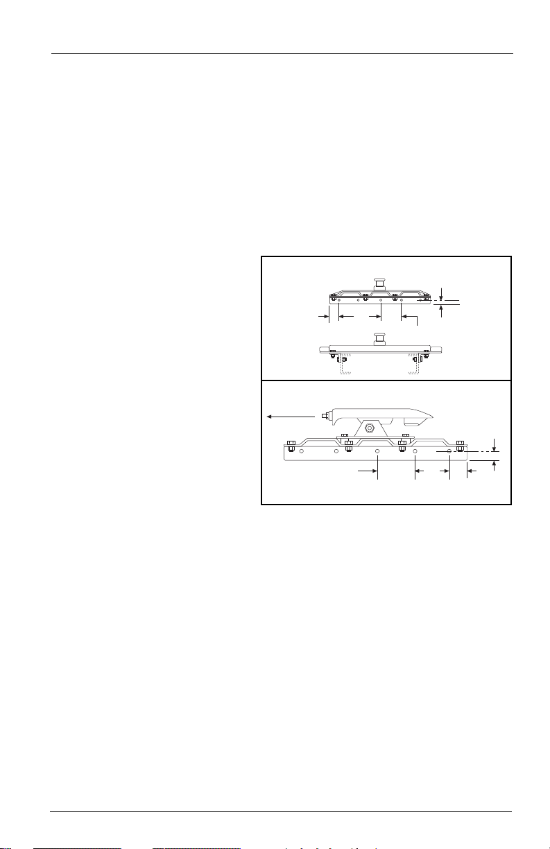
Figure 1 for
FRONT OF
VEHICLE
KINGPIN ATTACHMENT
1˝ MIN.
2˝
8˝ MAX.
FIFTH WHEEL ATTACHMENT
8˝ MIN.
Figure 1
1˝ MIN.
2˝
XL-FW485 Rev A
3
INSTALLATION INSTRUCTIONS
25/8˝
26˝
20˝
40˝
31/4˝
3
1
/4˝
9
7
/8˝
27/8˝
continued
Tractor Coupler Mounting (Kingpin or Fifth Wheel)
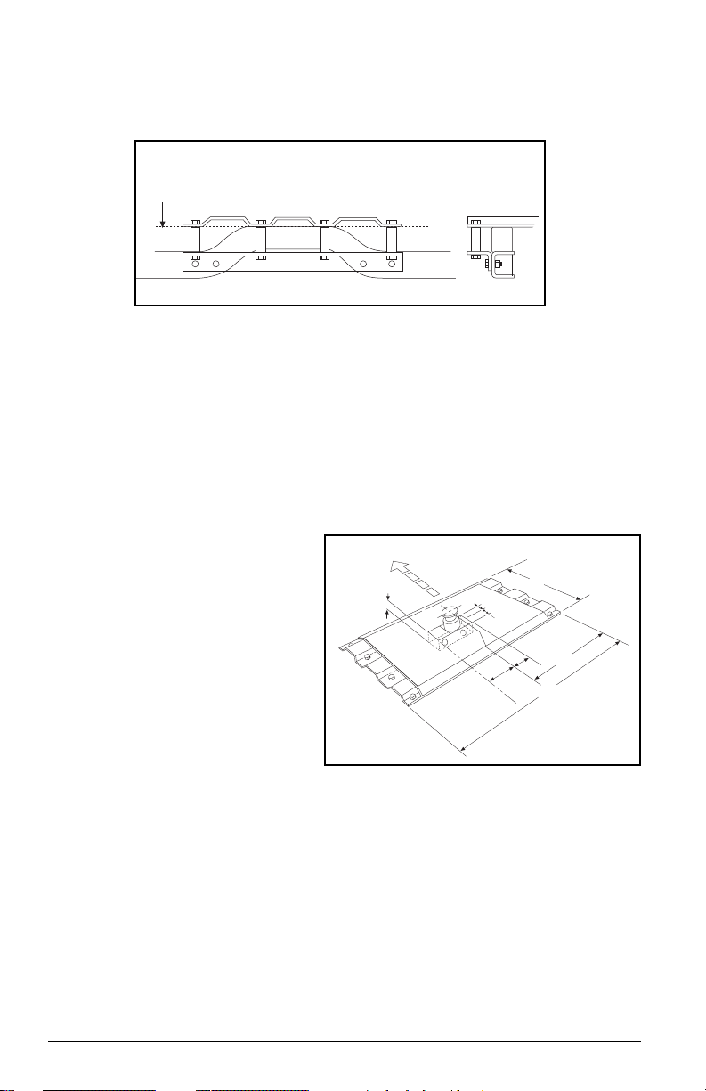
Non-Straight Frame – With or Without a Body:
PREFERRED MOUNTING METHOD
BODY FLOOR
Figure 2
1. Full Angle Mounting – Preferred
In addition to the general installation recommendations listed on the previous
page, the following specific recommendations must be followed:
A. If a folding kingpin is to be installed, the following procedures must be
completed before going to step C:
1. The 40˝ dimension of the kingpin plate must be installed parallel with the
rear axle with the upright kingpin centered between the pickup sides.
2. Check under the floor in the area where the kingpin is to be located to avoid
interference with the differential, drive shaft or frame cross members. The
area should be clear 3˝ below the floor when the springs are fully bottomed.
3. Cut a hole in the truck floor
to receive the folding
kingpin box (see
Figure 4).
NOTE: The folding kingpin base is
offset. Cut three sides of the floor and
fold the flap down and out of the way.
B. Initially position the coupler
plate in the box or on the frame in
the desired position (at least 2˝
ahead of the rear axle). If possible,
the coupler plate should be
attached using a full-length
mounting angle (3˝ x 3˝ x 5/16˝
minimum, ASTM A-36) on each
side (see
Figure 2).
C. A minimum of four (4) Grade 8, 1/2" diameter (minimum) bolts must be applied
to attach each mounting angle to the frame rail.
D. Proper length tube spacers (3/4˝ I.D. x 1 1/2˝ O.D. recommended) must be used
to shim the distance between the mounting angle and the coupler mounting
plate (minimum of 4 per side).
FRONT OF TRUCK
Figure 4
4
XL-FW485 Rev A

INSTALLATION INSTRUCTIONS
1/4 2 – 6
TYP.
3/16 2 – 6
TYP.
continued
ACCEPTABLE MOUNTING METHOD
BODY FLOOR
Figure 3
2. Tab Mount - Acceptable
In addition to the general installation recommendations listed on the previous page,
the following specific recommendations must be followed:
A. If a full-length mounting angle is impractical, an angle TAB mount, as shown in
Figure 3, is acceptable. The angle TABS should be 3˝ x 3˝ x 3/8˝ x 3˝ long
minimum, using an ASTM A36 steel. A minimum of 4 TABS per side are required.
B. The TABS must be attached to the tractor frame using 1/2" diameter (minimum)
Grade 8 fasteners.
C. Proper length tube spacers (3/4˝ I.D. x 1 1/2˝ O.D. recommended) must be used
to shim the distance between the TAB angles and the coupler mounting plate.
Tractor Coupler Mounting – Kingpin or Fifth Wheel Mount:
The kingpin mounting box is designed to be attached to the trailer frame by welding. It
is imperative, therefore, that the attachment is substantial enough to develop the full
strength of the hitch.
When welding, use a procedure which assures a sound, good quality
cause distortion and damage and underwelding may not develop sufficient strength. A
low hydrogen process and AWS E70XX filler metal are recommended. Take precautions
to insure that the trailer electrical system is not damaged by the welding.
1. Weld as shown in Figure 5, making 1/4˝ fillet welds on the inside and 3/16˝ fillet welds
on the outside, with skip welds 2˝ long on approximately 6" centers (weld 2˝, skip
4˝). Weld inside opposite skips on the outside.
2. Install and adjust inner box to required height. Use the six (6) Grade 5 fasteners
provided (2 each hole series) and tighten to 65 ft. - lbs.
3. When installing a fifth wheel
on a trailer mounting box, be
certain that the open end of
the fifth wheel faces the front
of the trailer (see
XL-FW485 Rev A
weld and which protects the operator and others. Over-welding may
Figure 7A).
Figur
e 5
5
F
RONT OF VEHICLE
CORRECT ENGAGEMENT
M
ounting Box
for Fifth Wheel
t
o Trailer
C
HECK NO. 3
N
o Space
between Fifth
W
heel and
Kingpin Plate
No Space
Bed of
Truck
Space
S
PACE
INCORRECT ENGAGEMENT
Mounting Box
for Fifth Wheel
to Trailer
Bed of Truck
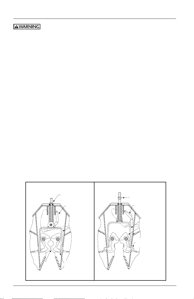
OPERATING INSTRUCTIONS
LOCKS SHOWN IN CLOSED POSITION
CHECK NO. 1
Nut Seated on
Fifth Wheel
CHECK NO. 2
Secondary Lock
Behind Yoke
Yoke
Yoke Flush with
Ends of Locks
Locks
LOCKS SHOWN IN OPEN POSITION
NOTE:
Nut away from
Fifth Wheel
NOTE:
Secondary Lock
away from Yoke
Yoke
NOTE: Locks
Extend through
Window to Open
Locks
SOLID
STUD
YES!
PIPE
RELEASE
HANDLE
RELEASE
HANDLE
NO!
ADJUSTING
BOLT & NUT
NO!
PUSH
TOWARD
TRAILER
Relative to tractor/trailer operations, there are other checks, inspections,
and procedures not listed here, which are necessary, prudent, and/or
required by law. The following is in addition to these, and pertains to the fifth wheel only.
Perform these procedures with the area clear of obstacles and other personnel.
Coupling Procedures
1. Check out the equipment before coupling.
A. Make sure that the fifth wheel is properly lubricated, that the locks are open,
and that the ramps are tilted in the proper position.
B. Make sure the mounting of the fifth wheel is in good condition and is tight.
C. Make sure the power/brake line and breakaway line (if the trailer is equipped
with electric brakes) and clear of the coupling area.
2. If the tractor is equipped with a body, lower the tailgate.
3. Back up close to the trailer, centering the kingpin on the crotch of the fifth wheel.
STOP!
4. Chock the trailer wheels.
5. Check the trailer height for coupling. The fifth wheel should just touch the kingpin
plate; adjust the landing gears as necessary.
6. Back
7. Visually check to see that the kingpin is in the fifth wheel lock.
8. Visually check that the locks are properly locked on the kingpin by the following (3) checks.
slowly under the trailer, keeping the kingpin centered in the crotch of the fifth
wheel until the fifth wheel locks firmly on the kingpin. Pull forward to check the
completeness of the coupling as an initial check.
CHECK 1
The adjustment nut must be seated against the fifth wheel (see Figure 6A).
CHECK 2
The secondary lock must be behind the yoke (see Figure 6A).
Figure 6A Figure 6B
6
XL-FW485 Rev A

F
RONT OF VEHICLE
CORRECT ENGAGEMENT
M
ounting Box
for Fifth Wheel
t
o Trailer
C
HECK NO. 3
N
o Space
between Fifth
W
heel and
Kingpin Plate
No Space
Bed of
Truck
Space
S
PACE
INCORRECT ENGAGEMENT
Mounting Box
for Fifth Wheel
to Trailer
Bed of Truck
OPERATING INSTRUCTIONS
SOLID
STUD
YES!
PIPE
RELEASE
HANDLE
RELEASE
HANDLE
NO!
ADJUSTING
BOLT & NUT
NO!
PUSH
TOWARD
TRAILER
Coupling Procedures continued
CHECK 3
The fifth wheel must be flush with the kingpin plate (see Figure 7A).
A direct visual inspection is required to assure proper coupling. Do not
use any fifth wheel which does not operate properly.
continued
9. Connect the
power/brake
Figure 7A
line(s).
10. If the trailer is
equipped with
electric brakes,
connect the
breakaway switch
line.
11. Retract the
landing gears,
raise the tailgate,
Figure 7B
pick up the wheel
chocks.
Uncoupling Procedure
1. Set trailer brakes and chock trailer wheels.
2. Lower the landing gear; when the foot pad contacts the ground, crank two or three
additional turns to reduce the vertical load on the fifth wheel. Do not raise the fifth
wheel off the kingpin plate.
3. If the truck/tractor is equipped with a body, lower the tailgate.
4. Disconnect the power/brake line and, if the
trailer is equipped with electric brakes,
unhook the breakaway switch line. Do not
disconnect at the switch.
5. Open the fifth wheel locks by . . .
A. pulling the release handle or . . .
B. from the driver’s side, slide a pipe
release handle over the solid stud,
located next to the adjusting bolt and
push toward the rear of the vehicle
(see
handle.
6.
Drive away from the trailer slowly.
e 8
Figur
). Remove and stor
7. Raise the tailgate if so equipped.
XL-FW485 Rev A
e the
Figure 8
7

MAINTENANCE PROCEDURES
1/4 2 – 6
TYP.
3/16 2 – 6
TYP.
1. All maintenance must be performed by a qualified person using
proper tools and safe procedures.
2. All maintenance must be performed while the tractor is uncoupled
from the trailer.
As-Needed Lubrication
1. Keep a water-resistant lithium-base grease applied to the trailer contact surface of
the fifth wheel plate.
2. Lubricate all moving parts with a light, rust-resistant oil.
3. Apply a light grease through the grease zerks at the pivot points and the cam.
Periodic Inspections and Adjustments
NOTE: All of the following must be performed every 30,000 miles or 3 months, whichever
comes first. Perform the inspections after steam cleaning to assure a good inspection.
Inspection — General
1. Inspect the fifth wheel and the kingpin mountings. Check torque and replace any
missing or damaged bolts. Check for broken or distorted components and repair or
replace as needed.
2. Inspect the fifth wheel assembly for bent, worn or broken parts. Replace with
HOLLAND parts only.
Fifth Wheel Locking Mechanism Inspection and Adjustment
1. Check the operation of the fifth wheel locking mechanism using a HOLLAND
TF-TLN-1000 (2˝ kingpin) or TF-TLN-1500 (31/2˝ kingpin) Lock Tester. Inspect for
proper locking as described in the “Operating Instructions” in this manual.
Do not use any fifth wheel which does not operate properly.
2. Check adjustment of the fifth wheel locks and adjust as required. The lock adjusting
nut is located at the front edge of the fifth wheel (see Figure 6A on page X). With
the wheel locked around the lock tester, tighten or loosen the nut until the rubber
washer seats snugly against the fifth wheel (but can still be turned by hand).
Viewed from the adjusting nut, a counter-clockwise rotation of the nut will allow
the yoke (see Figure 6A) to move in and tighten the locks on the kingpin. A
clockwise rotation will pull the yoke out and loosen the locks. Remove and reinsert
the lock tester to verify proper adjustment and coupling.
3. Relubricate by applying a light, rust-resistant oil to all moving parts.
8
XL-FW485 Rev A

XL-FW485 Rev A
9

10
XL-FW485 Rev A

WARRANTY
COMMERCIAL
PRODUCTS
WARRANTY
olland warrants all Commercial Products (products
H
other than those normally used for personal, family, or
household purposes) manufactured by it, when
properly installed, to be free from defects in material
and workmanship under normal use and service for a
period of two (2) years from the date of manufacture,
with the exception of elevating fifth wheels for which
the warranty period is 180 days.
This warranty is void with respect to any product
which has been altered in any way from its
manufactured condition, such as intentional
modification, accident, corrosion, misuse, failure to
provide necessary and reasonable maintenance and is
exclusive of normal wear.
The sole responsibility of Holland under this warranty
is limited to repairing or replacing at the factory any
part or parts which are returned, with transportation
charges prepaid,and are found to be defective to the
satisfaction of Holland.Written authorization from
Holland must be obtained prior to returning any part
or parts. No charges for transportation or for labor
performed on Holland products by unauthorized
persons will be allowed under this warranty.
XL-FW485 Rev A
Holland shall not be liable, in any event, for proximate,
incidental, consequential or other damages, including
but not limited to damages for loss of production
or injury to persons or property arising out of any
breach of this warranty.
THERE ARE NO WARRANTIES, EXPRESS OR
IMPLIED, INCLUDING THE WARRANTY OF
MERCHANTABILITY OR A WARRANTY OF
FITNESS FOR A PARTICULAR PURPOSE
EXTENDING BEYOND THAT SET FORTH ABOVE.
Warranty
11

12
Copyright © July 2005 • The Holland Group, Inc.
maintain this fifth wheel could result in
tractor and trailer separation causing death
or serious injury to others.
operation, and maintenance of this product. Read and
Failure to properly install, operate, or
understand this information.
IMPORTANT: Enclosed is important information for the installation,
XL-FW485 Rev A
 Loading...