

Owners Manual
FW31 and XA-311 Series
®
Fifth Wheels
with Traditional Slider
• Operation
• Maintenance Procedures
• Comprehensive Warranty
XL-FW436-01 Rev B
GENERAL SAFETY INFORMATION
Notes, Cautions, and Warnings
You must read and understand all of the safety procedures presented in this manual
before starting any work on the SAF-HOLLAND product.
NOTE: In the United States, work shop safety requirements are defined by federal
and/or state Occupational Safety and Health Act or equivalent laws in other
countries. This manual is written based on the assumption that OSHA or other
applicable employee safety regulations are followed by the location where work is
performed.
Proper tools must be used to perform the maintenance and repair procedures
described in this manual. Many of these procedures require special tools.
Throughout this manual, you will notice the terms “NOTE”, “IMPORTANT”,
“CAUTION”, and “WARNING” followed by important product information. So that
you may better understand the manual, those terms are as follows:
NOTE: Includes additional information to enable accurate and easy performance
of procedure.
IMPORTANT: Includes additional information that if not followed could lead
to hindered product performance.
Used without the safety alert symbol, indicates a potentially
hazardous situation which, if not avoided, may result in property
damage.
Indicates a potentially hazardous situation which, if not avoided,
may result in minor or moderate injury.
Indicates a potentially hazardous situation which, if not avoided,
could result in death or serious injury.
Fifth Wheel Design and Intended Use
1. For pulling trailers with standard SAE kingpins which are in good condition and
securely mounted or locked in position in the trailer.
2. For on-highway hauling applications.
3. Within the capacities stated in SAF-HOLLAND literature.
4. As recommended in SAF-HOLLAND literature (available from www.safholland.us).
Holland Fifth Wheels are NOT Designed or Intended For
1. Use with non-SAE kingpins, such as kingpins which are bent, improper size or
dimensions, not secured to maintain SAE configuration, or which are installed in
warped trailer bolster plates.
2. Tow-away operations which damage or interfere with the proper operation of the
fifth wheel.
3. The attachment of lifting devices.
4. The transport of loads in excess of rated capacity.
5. Off-highway applications and use.
6. Applications other than recommended.
2 SAF-HOLLAND, Inc. XL-FW436-01 Rev B
OPERATION INSTRUCTIONS
➠
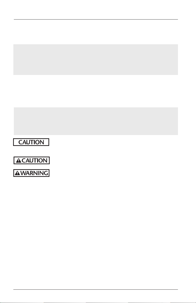
Failure to properly install, operate, or maintain this fifth
wheel may result in tractor and trailer separation which, if
not avoided, could result in death or serious injury.
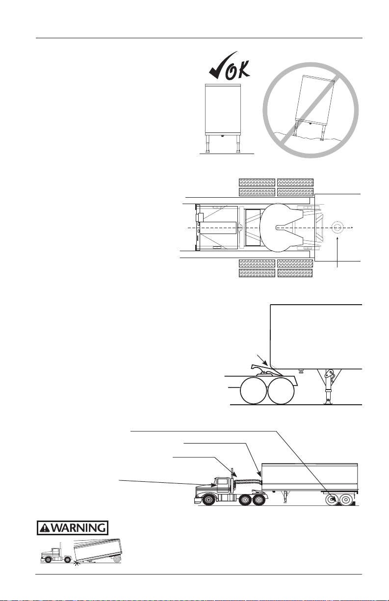
Fifth Wheel Inspections
1. Inspect the fifth wheel and mounting.
• Confirm that the lube plates
are in place and firmly attached.
• Tighten loose fasteners.
• Replace missing fasteners.
• Repair/replace missing,
cracked or otherwise
damaged components.
• For sliding fifth wheels, make sure both plungers
are fully engaged (see Page 14).
2. Make sure the lock is open. To open the lock, pull the release handle all the way
out. If Air Release equipped, set tractor brakes and actuate the fifth wheel control
valve to open the locks.
Grease
fitting
location
If locks are closed,
pull release
handle all the
way out.
Locks are closed
and the fifth
wheel is locked.
DO NOT
attempt to
couple!
3. Inspect the lock jaws. If they appear dry,
apply grease to lock jaws and front of throat
directly or through the lube tube grease
fitting. Coupled lock jaws and front of throat
can be lubricated through lube tube grease
fitting (see page 15).
4. Tilt the ramps down.
XL-FW436-01 Rev B SAF-HOLLAND, Inc. 3
TILT
DOWNWARD
The locks are
open and ready
to couple.
OPERATION INSTRUCTIONS con ti nu ed
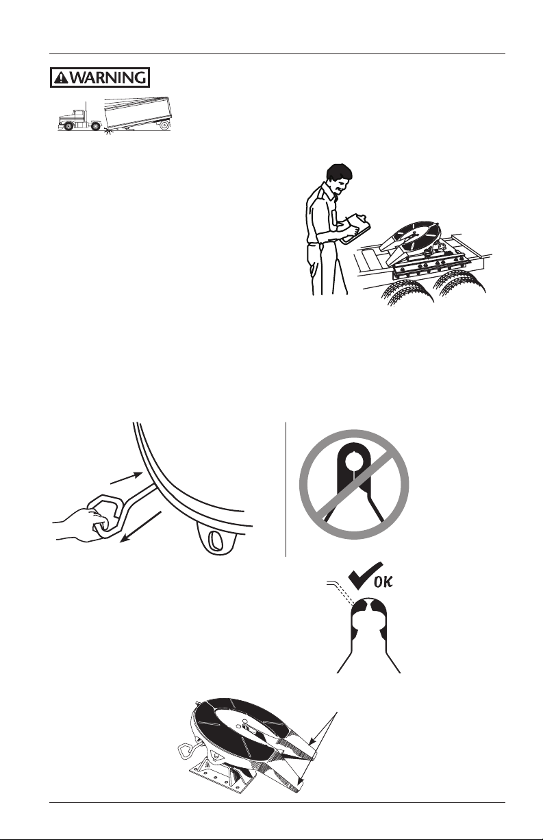
Trailer Upper Coupler Inspections
1. Inspect the leading edge of the trailer
bolster/skid plate. It must be free of
any square or sharp edges.
2. Make sure there are no bolts or nuts
extending below the bolster/skid plate
within 6˝ of the fifth wheel travel path
while coupling.
3. The area that is supported by the fifth
wheel should be free of any large
holes or gouges.
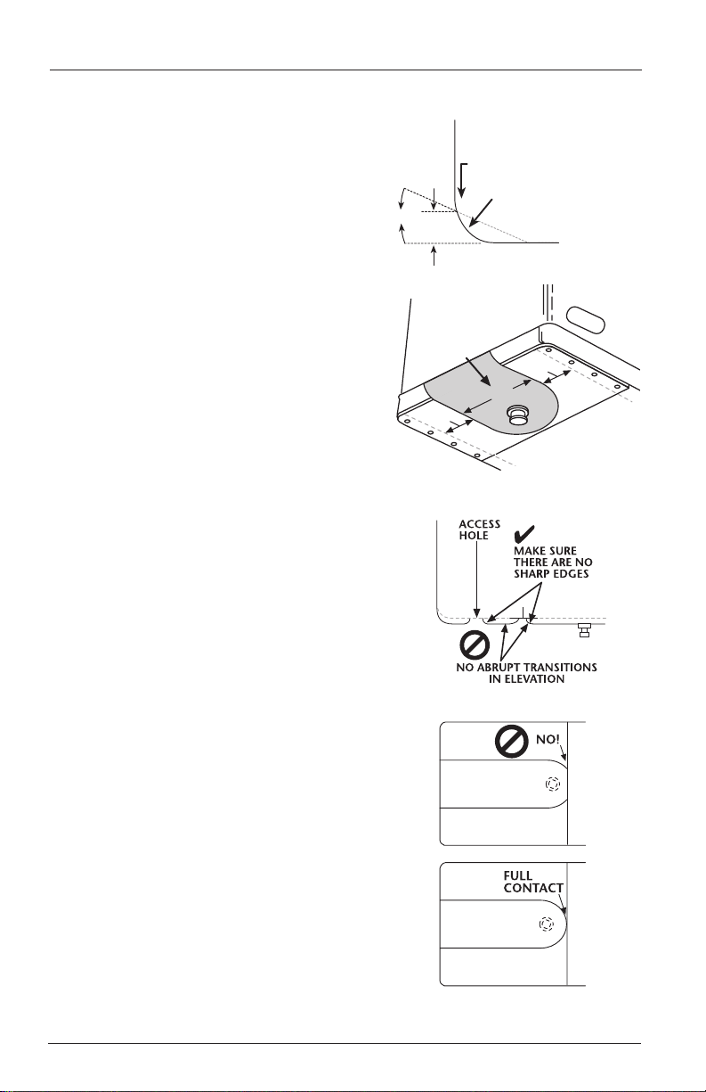
4. Any access holes that the fifth wheel
passes below should have chamfered
or radius edges.
5. Check that any splits from the skid
plate to bolster plate are welded
adequately and that there are no
sharp edges or abrupt changes in
elevation.
6. The upper coupler should extend
adequately rearward to maintain full
contact with the fifth wheel during
tight turning. If it does not, at a
minimum, the rear edges should be
chamfered or radius edges.
20ϒ
2˝
min.
Keep path of fifth
wheel free of
large holes
& gouges
6˝min.
✔
CHAMFERED (Preferred)
or LARGE RADIUSED
LEADING EDGE
6˝min.
40˝
Keep bolts and nuts
clear of this area
7. Make sure that any upper coupler
residual grease is free of heavy coarse
grit.
8. Ensure that the upper coupler fifth
wheel contact surface is free of rust.
Do not paint the contact area! The
area should be conditioned with rust
inhibitor such as a light oil.
9. Inspect the kingpin for excessive wear
and damage (use Holland tool TF-0110
Kingpin Gage) along with bolster bow
(see SAE 1700).
✔
4 SAF-HOLLAND, Inc. XL-FW436-01 Rev B
OPERATION INSTRUCTIONS
➠
Coupling Procedures
1. Make sure the coupling area is
flat, level, and clear of persons and
obstacles.
2. Center the fifth wheel with the
kingpin and back up straight.
3. Back the tractor close to the
trailer and STOP.
continued
TRAILER
(TOP)
KINGPIN
Back in and
STOP!
4. Chock trailer wheels.
5. Connect brake lines and light cord.
6. Support slack in lines to prevent
interference.
7. Set trailer brakes.
Failure to properly install, operate, or maintain this fifth
wheel may result in tractor and trailer separation which, if
not avoided, could result in death or serious injury.
XL-FW436-01 Rev B SAF-HOLLAND, Inc. 5
OPERATION INSTRUCTIONS
➠
Coupling Procedures continued
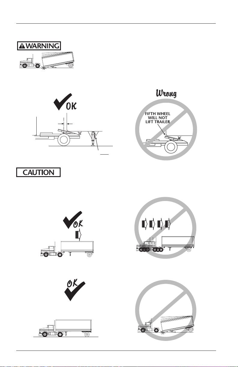
Failure to properly install, operate, or maintain this
fifth wheel could result in tractor and trailer separation,
causing death or serious injury to others.
8. Adjust the trailer height so the fifth wheel will lift the trailer.
The trailer should contact the fifth wheel 4˝ – 6˝ behind the fifth wheel bracket pin.
continued
➠
FIFTH WHEEL
4˝- 6˝
MUST LIFT
TRAILER
➠
FIFTH WHEEL
TILTED DOWN
Attempting to couple with the trailer at an improper height
could result in a false or improper coupling.
9. Slowly back into the trailer.
BACK INTO TRAILER
SLOWLY
USE LOW
GEAR
➠
10. Do a pull test as an INITIAL CHECK.
➠
➠
PULL TEST
➠
DO NOT
BACK INTO
TRAILER FAST
➠ ➠ ➠ ➠
WITHOUT
PULL TEST
➠
PULL FORWARD WITH TRACTOR
6 SAF-HOLLAND, Inc. XL-FW436-01 Rev B
 Loading...