


Owners Manual
FW2800 and FW2900 Series
Hydraulic Elevating Fifth Wheels
• Operation
• Maintenance Procedures
• Troubleshooting
XL-FW428-01 Rev A

OPERATING INSTRUCTIONS
Notes, Cautions, and Warnings
You must read and understand all of the safety procedures presented in this manual
before starting any work on the SAF-HOLLAND product.
NOTE: Work shop safety requirements are defined by federal and/or state
Occupational Safety and Health Act in the United States, or equivalent laws
in other countries. This manual is written based on the assumption that
OSHA or other applicable employee safety regulations are followed by the
location where work is performed.
Proper tools must be used to perform the maintenance and repair procedures
described in this manual. Many of these procedures require special tools.
Throughout this manual, you will notice the terms “NOTE”, “IMPORTANT”,
“CAUTION”, and “WARNING” followed by important product information. So that
you may better understand the manual, those terms are as follows:
NOTE: Includes additional information to enable accurate and easy performance
of procedure.
IMPORTANT: Includes additional information that if not followed could lead
to hindered product performance.
Used without the safety alert symbol, indicates a potentially
hazardous situation which, if not avoided, may result in property
damage.
Indicates a potentially hazardous situation which, if not avoided,
may result in minor or moderate injury.
Indicates a potentially hazardous situation which, if not avoided,
could result in death or serious injury.
Fifth Wheel Design and Intended Use
1. For pulling trailers with standard SAE kingpins which are in good condition and
securely mounted or locked in position in the trailer.
2. For on-highway hauling applications.
3. Within the capacities stated in SAF-HOLLAND literature.
4. As recommended in SAF-HOLLAND literature (available from www.safholland.us).
Holland Fifth Wheels are NOT Designed or Intended For
1. Use with non-SAE kingpins, such as kingpins which are bent, improper size or
dimensions, not secured to maintain SAE configuration, or which are installed in
warped trailer bolster plates.
2. Tow-away operations which damage or interfere with the proper operation of the
fifth wheel.
3. The attachment of lifting devices.
4. The transport of loads in excess of rated capacity.
5. Off-highway applications and use.
6. Applications other than recommended.
2 SAF-HOLLAND, Inc. XL-FW428-01 Rev A
OPERATING INSTRUCTIONS
Before You Begin
IMPORTANT: This unit is not intended for operation on public streets and
highways with the fifth wheel in the up position. Do not operate
this unit on public highways unless the fifth wheel manual
secondary lock is engaged. The fifth wheel must be in the full down
position and the lockdown pins (option -87) fully engaged.
IMPORTANT: Towing a trailer in the elevated position raises the center of
gravity and increases the risk of vehicle rollover. To avoid rollover,
do not travel at excessive speeds and do not make sudden turns
or maneuvers.
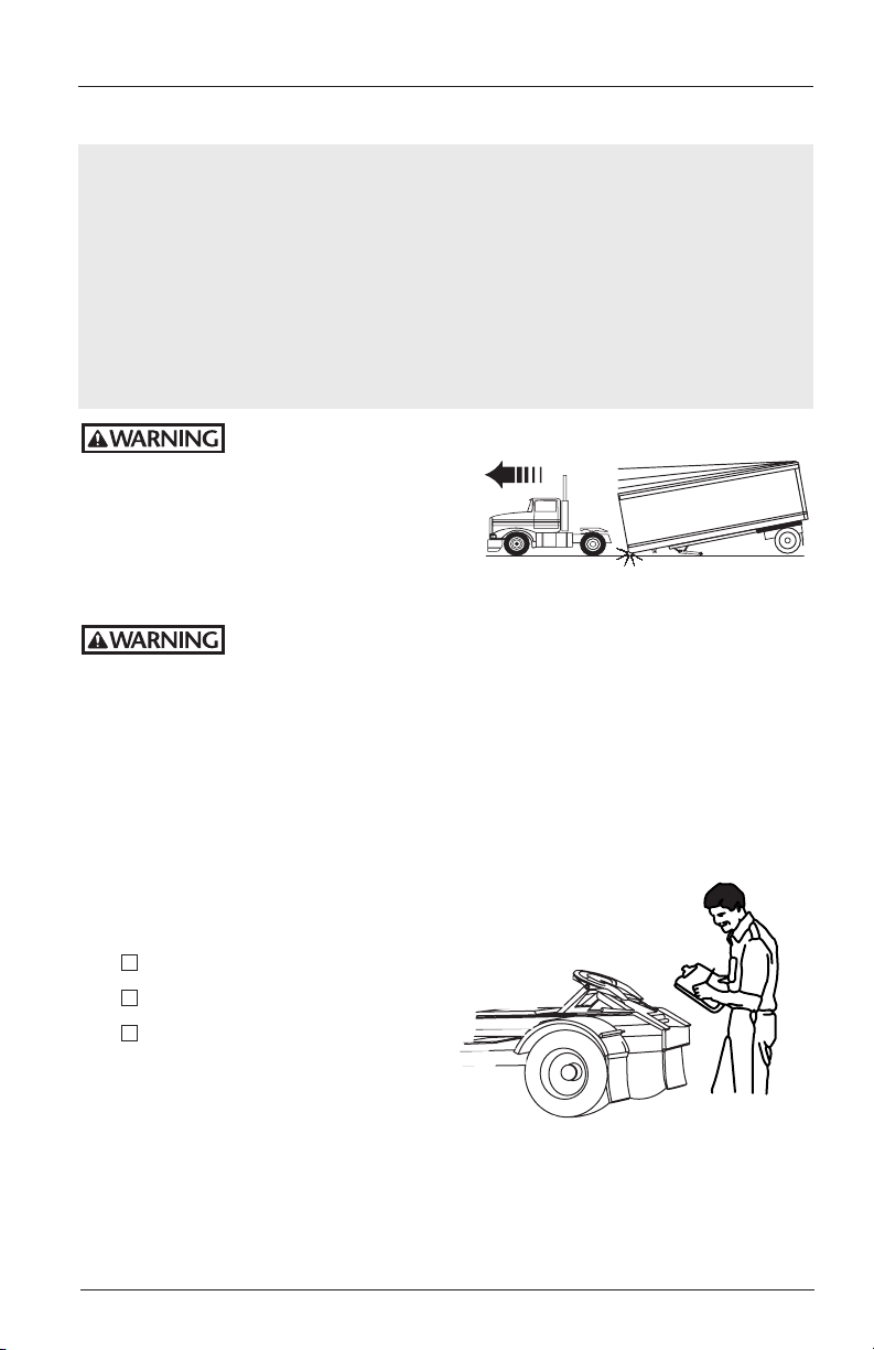
Failure to lower fifth wheel to full down position and engage
lockdown pins prior to
moving a coupled tractor
will increase vehicle
instability which, if not
avoided, could result in
serious unjury or death.
Failure to properly couple the fifth wheel according to these
instructions could result in tractor and trailer separation, causing
death or serious injury to others.
Fifth Wheel Inspections
1. Inspect the fifth wheel and mounting.
3
Tighten loose fasteners.
3
Replace missing fasteners.
3
Repair/replace missing,
cracked or otherwise
damaged components.
2. Inspect the lock jaws. If they
appear dry, apply grease to the
lock jaws and the front of the throat.
3. Tilt the ramps down.
XL-FW428-01 Rev A SAF-HOLLAND, Inc. 3
OPERATING INSTRUCTIONS
continued
General Coupling Procedures
1. Make sure coupling area is flat,
level and clear of persons and
obstacles.
2. Center fifth wheel with kingpin and
back up straight.
3. Back tractor close to trailer
and STOP.
INITIAL CONTACT OF TRAILER WITH
FIFTH WHEEL AT THIS POINT
4˝ APPROX.
TRAILER
(TOP)
KINGPIN
continued
4 SAF-HOLLAND, Inc. XL-FW428-01 Rev A
OPERATING INSTRUCTIONS
continued
General Coupling Procedures
4. Chock trailer wheels.
5. Connect brake lines
and light cord.
6. Support slack in lines
to prevent interference.
7. Set trailer brakes.
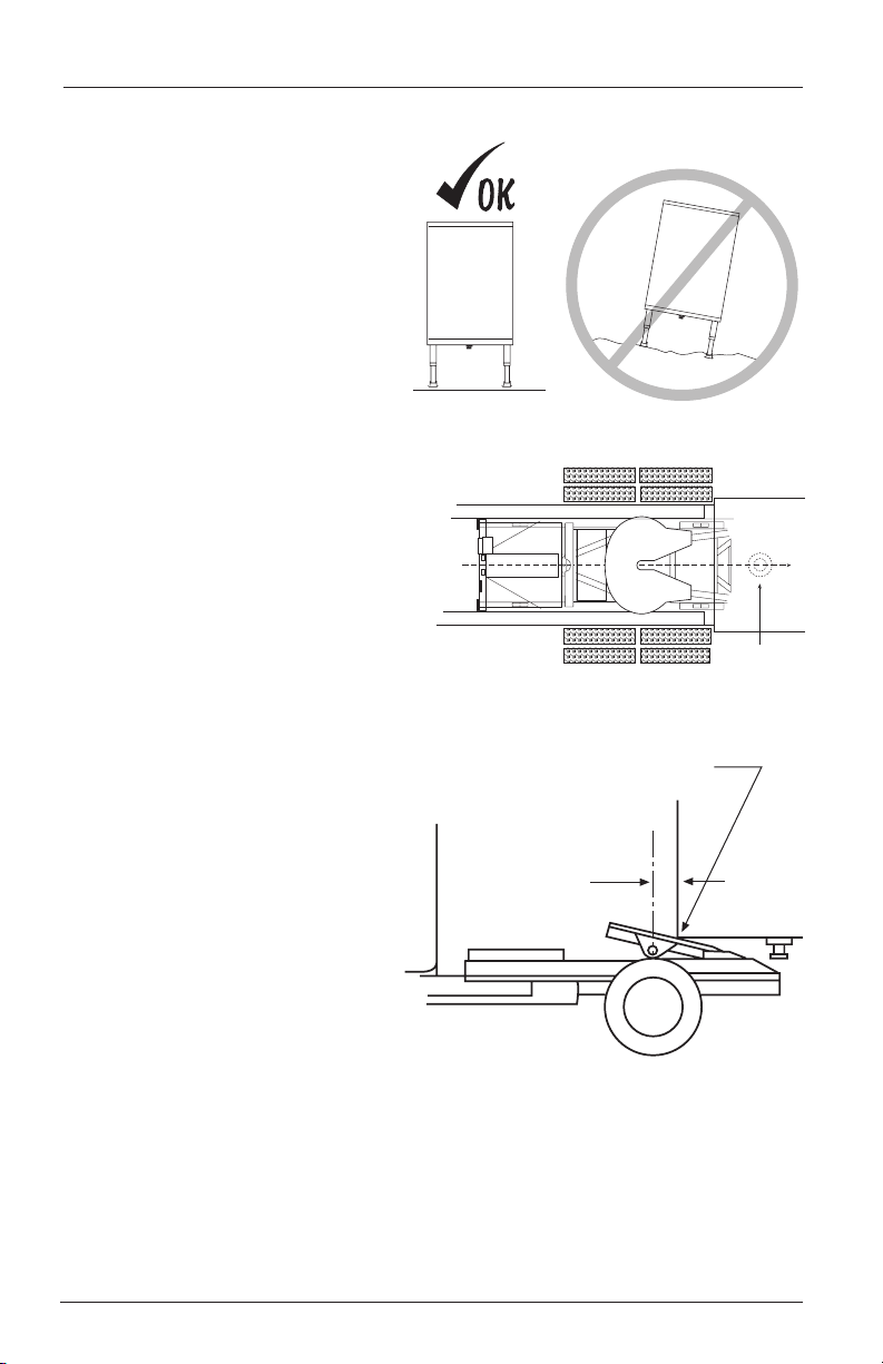
NOTE: Follow operating instructions for the landing gear that is installed on
your trailer to raise or lower landing gear and trailer.
8. Adjust the trailer height so the fifth
wheel will lift the trailer. The trailer
should contact the fifth wheel 4˝ – 6˝
behind the fifth wheel bracket pin. If
the trailer landing gear needs to be
raised or lowered for proper coupling
height, use low gear.
continued
4˝- 6˝
OK
FIFTH WHEEL
MUST LIFT
TRAILER
➠
➠
FIFTH WHEEL
TILTED DOWN
USE LOW
GEAR
Wrong
FIFTH WHEEL
WILL NOT
LIFT TRAILER
continued
XL-FW428-01 Rev A SAF-HOLLAND, Inc. 5

OPERATING INSTRUCTIONS
General Coupling Procedures continued
continued
9. Slowly back into the trailer.
BACK INTO TRAILER
SLOWLY
10. Do a pull test as an
INITIAL CHECK.
➠
➠
PULL TEST
➠
PULL FORWARD WITH TRACTOR
DO NOT
BACK INTO
TRAILER FAST
➠ ➠ ➠ ➠
11. Visual Inspection. GET OUT OF THE TRACTOR!
VISUALLY check that the lock is CLOSED!
DO NOT RELY ON SOUND.
1
3
➠
NO GAP!
2
3
WITHOUT
PULL TEST
➠
View looking into
the throat of the
fifth wheel
➠
Bolster plate
is flush with
the fifth wheel
LOCKS COMPLETELY CLOSED
AROUND KINGPIN
If you do not obtain a proper couple, repeat the coupling sequence.
NOTE:
DO NOT use any fifth wheel that fails to operate properly.
Failure to properly couple the fifth wheel according to these
instructions could result in tractor trailer separation, if not
avoided, could result in serious injury or death.
6 SAF-HOLLAND, Inc. XL-FW428-01 Rev A
Kingpin
Trailer
bolster plate
continued

OPERATING INSTRUCTIONS
continued
Coupling Procedures for Over-The Road Use
For private yard operation (yard-spotter) coupling instructions, proceed to page 9. The
two steps below are required for operation of this fifth wheel on public streets.
IMPORTANT: This unit is not intended for operation on public streets and
highways with the fifth wheel in the up position. Do not operate
this unit on public highways unless the fifth wheel manual
secondary lock is engaged. The fifth wheel must be in the full
down position and the lockdown pins (option -87) fully engaged.
Failure to lower fifth wheel to full down position and engage
lockdown pins prior to moving a coupled tractor will increase vehicle
instability which, if not avoided, could result in serious injury or death.
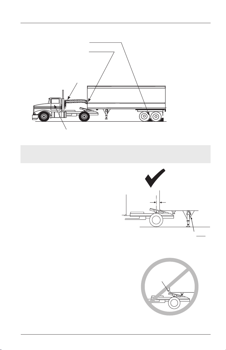
1. Unhook and engage the secondary lock for operation on public streets.
1˝ MAXIMUM
ROD VISIBLE
HANDLE IS IN
2. Place the fifth wheel in the full down position and engage the top plate lock
down pins.
NOTE: The fifth wheel must be fully lowered to allow the lockdown pins to
engage. If the wheel is up too high, put the transmission in neutral and
engage the power take off (PTO). Set the engine speed to 1,000 to 1,200
r.p.m. and operate the control valve to lower the trailer and fifth wheel
until they are all the way down.
To engage the pins, move the handle from the “Yard Use” position (handle
pointing toward the front of the tractor), to the “Highway Use” position (handle
pointing toward the rear of the tractor) as shown below. This operation is also
illustrated on the instruction label located directly above the handle on the left
front side of the fifth wheel frame assembly.
FIFTH WHEEL IN FULL DOWN POSITION
HANDLE IN “HIGHWAY USE” POSITION
“YARD USE” POSITION
continued
XL-FW428-01 Rev A SAF-HOLLAND, Inc. 7

OPERATING INSTRUCTIONS
continued
Coupling Procedures for Over-The Road Use continued
3. Confirm that the lockdown pins
are in the extended position. Both
pins should be fully extended through
the fifth wheel assembly frame rails and
through the lockdown plates.
NOTE: Follow operating instructions for
the landing gear that is installed
on your trailer to raise or lower
landing gear and trailer.
4. Retract landing gear in accordance with
manufacturer’s instructions.
5. Check the brake lines and light cord.
Remove the wheel chocks and continue
with a pre-trip inspection.
LOCK PINS EXTENDED
(FOR HIGHWAY USE)
USE
LOW
GEAR
USE
HIGH
GEAR
SECURE
CRANK
continued
8 SAF-HOLLAND, Inc. XL-FW428-01 Rev A

OPERATING INSTRUCTIONS
continued
Coupling Procedures for Private Yard
(Yard-Spotter) Operation
1. Before raising the fifth wheel,
confirm that the lockdown pins
are in the retracted position. Both
pins should be fully retracted.
2. Put the transmission in neutral and
engage the power take-off (PTO).
3. Set the engine speed to 1,000 to 1,200 r.p.m.
and operate the control valve to raise the trailer
to the full height of the fifth wheel.
4. Disengage the PTO, remove the blocks, and
release the the trailer brakes.
LOCK PINS RETRACTED
General Uncoupling Procedures
1. Position the tractor and trailer on firm,
level ground – clear of obstacles and people.
2. Set the trailer brakes.
3. Slowly back the tractor tightly against the trailer.
(FOR YARD USE)
4. Set the tractor brakes.
5. Chock the trailer wheels.
6. Disconnect the brake lines and light cord.
Attach the brake line to a dummy coupling
to keep the line clean.
continued
XL-FW428-01 Rev A SAF-HOLLAND, Inc. 9

OPERATING INSTRUCTIONS
support
may be required.)
continued
Uncoupling Procedures for Over-The Road Use
For uncoupling procedures for Yard-Spotter operations, proceed to Step 1, Page 11.
NOTE: Follow operating instructions for the landing gear that is isntalled on
your trailer to raise or lower landing gear and trailer.
1. Extend landing gear in accordace with
manufacturer’s instructions.
USE
2. Switch to low gear and crank
an additional 4-8 turns.
HIGH
GEAR
Do not raise the trailer off the
fifth wheel.
3. Pull the secondary lock handle
and hook it on the rib (located on
the right side of the fifth wheel).
Proceed to step 4 on page 11.
USE
LOW
GEAR
SECURE
CRANK
Firm ground.
(Additional
10 SAF-HOLLAND, Inc. XL-FW428-01 Rev A
continued

OPERATING INSTRUCTIONS
continued
Uncoupling Procedures for Private Yard
(Yard-Spotter) Operation
1. Put the transmission in neutral and engage the PTO.
NOTE: The PTO must be engaged (pumped down) when lowering the fifth wheel.
2. Set the engine speed to 1,000 to 1,200 r.p.m. and operate the control valve to
lower the trailer until it rests on the trailer supports (landing gear).
3. Disengage the PTO.
4. Return to the tractor cab and push the fifth wheel lock
control valve and hold it in as you pull slowly out
from the trailer.
Never push the fifth wheel lock control
valve when the wheel is up or while
traveling.
Failure to lower fifth wheel to full
down position and engage lockdown
pins prior to pushing the fifth wheel
lock control valve could result in tractor
trailer separation which, if not avoided,
could result in serious injury or death.
FIFTH WHEEL
LOCK CONTROL
WARNING
NEVER PUSH WHEN WHEEL
IS UP OR WHILE TRAVELING.
TRAILER CAN SEPERATE
AND CAUSE DEATH OR
SERIOUS INJURY.
FIFTH WHEEL LOCK
CONTROL VALVE
continued
XL-FW428-01 Rev A SAF-HOLLAND, Inc. 11

TROUBLESHOOTING
PROBLEM: Will not lift.
POSSIBLE CAUSE SOLUTION
Insufficient oil ..............................................Check oil level. The tank should contain 4˝ of oil in the
down position. If low, add oil.
PTO not engaged ........................................Engage the PTO. Check the shifter for
proper operation.
Engine r.p.m. too low ..................................Increase to 1,000 to 1,200 r.p.m.
Control valve ...............................................Check for full throw.
Load exceeds capacity .................................Reduce the weight of the trailer.
Flow restriction ............................................ Check for ruptured or collapsed hoses; check oil filter;
clear the lines.
Pump is losing prime ................................... Raise the oil tank and/or line above the pump inlet.
Pump is running hot .................................... PTO left in gear; disengage when not in use.
Oil foaming (contains air) ...........................Tighten all fittings and check for leaks.
PROBLEM: Raises or lowers slowly.
POSSIBLE CAUSE SOLUTION
PTO not engaged ........................................Engage the PTO.
Engine r.p.m. too low .................................. Increase to 1,000 to 1,200 r.p.m.
Control valve ...............................................Check for full throw.
Incorrect pressure ........................................Raising pressure circuit should be 1,800 p.s.i.; lowering
circuit pressure should be 150 p.s.i.
Flow restricted .............................................Check for ruptured or collapsed hoses, check oil filter,
clear lines.
PROBLEM: Oil tank is overflowing.
POSSIBLE CAUSE SOLUTION
Too much oil in the system ......................... Check oil level. Tank should contain 4˝ of oil in the
down position.
Oil foaming (contains air) ...........................Tighten all fittings and check for leaks.
12 SAF-HOLLAND, Inc. XL-FW428-01 Rev A

TROUBLESHOOTING
continued
PROBLEM: Will not lower.
POSSIBLE CAUSE SOLUTION
PTO not engaged ........................................PTO must be engaged when lowering unit.
Engine r.p.m. too low .................................. Increase to 1,000 to 1,200 r.p.m.
PROBLEM: Will not stay in raised position.
POSSIBLE CAUSE SOLUTION
Pressure loss ................................................Air in hydraulic oil. Let stand until clear. Tighten fittings
and check for leaks. Check oil level.
Pressure loss ................................................Leak in system. Tighten fittings and check for leaks.
Pressure loss ................................................Damaged hydraulic cylinder. Isolate and pressurize to
check. Repair or replace.
Pressure loss ................................................Faulty valves. Clean and reassemble, or, replace
control and release valves in manifold.
PROBLEM: Cracking or breaking of lift arms.
POSSIBLE CAUSE SOLUTION
Rough terrain ..............................................Improve road surface.
Overload ......................................................Reduce trailer weight.
Lack of lubrication .......................................Lubricate per maintenance instructions.
Worn shafts, bushings,
and housings ............................................. Replace
Incorrect pressure ........................................Lifting circuit pressure should be 1,800 p.s.i.
PROBLEM: Fifth wheel will not unlock properly.
POSSIBLE CAUSE SOLUTION
Accumulated grease and
dirt in mechanism ..................................... Steam clean thoroughly and lubricate with light,
rust-resistant oil.
Insufficient lubrication .................................Lubricate thoroughly with light, rust-resistant oil.
Faulty release air cylinder ............................Replace air filter and/or cylinder.
Worn or damaged parts. .............................Rebuild or replace.
continued
XL-FW428-01 Rev A SAF-HOLLAND, Inc. 13

MAINTENANCE INSTRUCTIONS
Weekly
1. Apply grease to all fittings.
2. Be sure the fifth wheel top plate is lubricated.
3. Check the hydraulic oil level.
4. Check the operation of the fifth wheel locking mechanism.
Monthly
1. Steam clean the entire unit thoroughly.
2. Inspect the elevating fifth wheel assembly and its mounting. Check the truck
frame for proper bolt torque; missing or damaged bolts; and broken, distorted, or
missing parts.
3. Check the fifth wheel locking mechanism for proper operation using a Holland
TF-TLN-1000 lock tester. Lubricate the locking mechanism with a light, rustresistant oil. When checking, move the lock tester fore and aft when it’s closed in
the locks. If play exceeds 3/8˝, rebuild or replace the top plate. See your Holland
distributor for top plates or rebuild kits.
4. Relubricate the assembly.
5. Inspect for leaks in the hydraulic system. Seal or replace any components, as
required.
6. Check the oil filter. Replace if necessary.
7. Check free play and pivot points in the elevating fifth wheel assembly. If free play
exceeds 1/8˝, replace the torque frame and/or shaft, as required.
continued
14 SAF-HOLLAND, Inc. XL-FW428-01 Rev A
MAINTENANCE PROCEDURES
continued
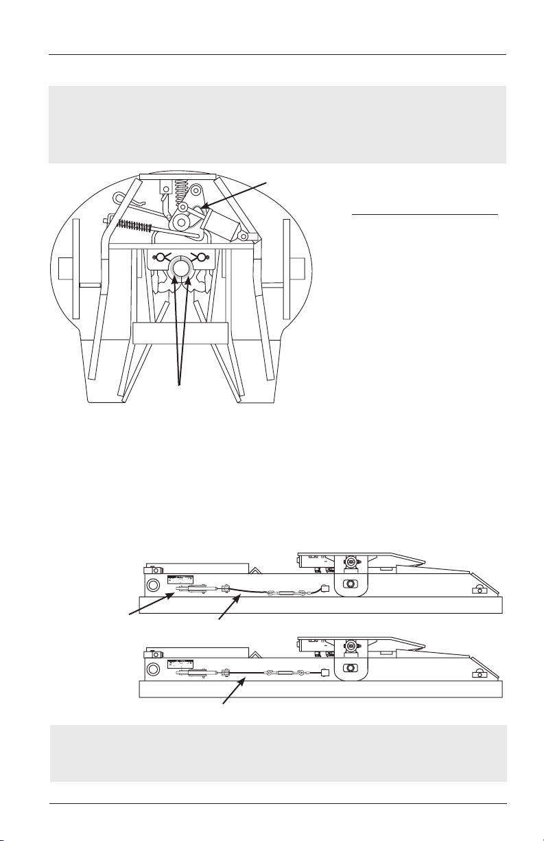
As-Needed Lubrication
IMPORTANT: Always maintain adequate lubrication in fifth wheel locking
mechanism, if it appears dry, apply grease to lock jaw and
front of throat directly, or through the lube tube grease fitting
located near the front left side of the fifth wheel.
LUBE THE CAM TRACK
Recommended Greases
A “low temp” grade recommended
for -30ºF or lower such as:
1. Cato Oil and Grease #5213
2. Craftsman Chemical Co. #LTF 2
3. Mystic LP-200 or equivalent
LUBE THE LOCKS
Check Top PlateLockdown Mechanism Cables
1. With the handle in the “Highway Use” position, the cable should be moderately
tight and not sagging excessively. If the cable is loose, rotate the turnbuckle to
tighten the cable.
2. After tightening, cycle the handle from the “Yard Use” position to the “Highway
Use” position several times to confirm that the pins are extending and retracting, as
described on page 8. Also confirm that the cables are not binding or being pinched.
HANDLE IS IN
THE HIGHWAY
USE POSITION
CABLE IS LOOSE - TIGHTEN BY ROTATING TURNBUCKLE
CABLE IS TIGHT - NO ADJUSTMENT NEEDED
NOTE: Do not use any fifth wheel that does not operate properly. If your
fifth wheel does not operate properly, contact your nearest Holland
Representative for assistance.
continued
XL-FW428-01 Rev A SAF-HOLLAND, Inc. 15

and maintenance of this product. Read and understand
E n g i n e e r i n g Y o u r R o a d t o S u c c e s s
this information.
IMPORTANT: Enclosed is important information for the operation
Failure to properly install, operate, or maintain
WARNING
this fifth wheel could result in tractor and trailer
separation which, if not avoided, could result in
serious injury or death.
SAF-HOLLAND USA, Inc. SAF-HOLLAND Canada Limited
888.396.6501 Fax 800.356.3929 519.537.3494 Fax 800.565.7753
Western Canada
604.574.7491 Fax 604.574.0244
XL-FWFW428-01 Rev A · 2009-07-07 · Amendments and errors reserved · © SAF-HOLLAND, Inc.
 Loading...