


GO THE DISTANCE.
FW83/XA-231
OWNERS MANUAL
FIFTH WHEEL
TECHNOLOGY
XL-FW418-01 Rev C
LowLube
Fifth Wheel
• Operation Instructions
• Maintenance Procedures
QUESTIONS OR COMMENTS?
CALL 1-888-396-6501
www.safholland.us

GENERAL SAFETY INSTRUCTIONS
Safety Signal Words
DANGER indicates an imminently hazardous situation
which, if not avoided, will result in death or serious injury.
WARNING indicates a potentially hazardous situation
h, if not avoided, could result in death or serious
whic
injury.
CAUTION indicates a potentially hazardous situation
whic
h, if not avoided, may result in minor or moderate
injury.
CAUTION used without the safety alert symbol indicates
a potentially hazardous situation which,if not avoided,
may result in property damage.
1. Keep Work Area Clean
Cluttered areas and benches invite accidents.
2. Keep fingers away from all potential pinch points in the fifth wheel.
3. All fifth wheel maintenance m
technician using proper tools and safe procedures.
4. Use only SAF-HOLLAND original parts.
5. Use Safety Goggles
Glasses or goggles not in compliance with ANSI or CSA can cause
ious injury when damaged or broken.
ser
6. Wear Proper Apparel
Do not wear loose clothing, gloves,neckties,jewelry (rings, wristwatches,
etc.) that can get caught in moving parts. Non-slip footw
ust be performed by a qualified service
ear is recommended.
FIFTH WHEEL DESIGN AND INTENDED USE:
Holland Fifth Wheels are Designed and Intended to Be Used:
1. For pulling trailers with standard SAE kingpins which are in good
condition and securely mounted or locked in position in the trailer.
2. Within the capacities stated in SAF-HOLLAND literature.
3. As recommended in SAF-HOLLAND literature (available from
.safholland.us).
www
Holland Fifth Wheels are NOT Designed or Intended For:
1. Use with non-SAE kingpins, such as kingpins which are bent, improper
size or dimensions, not securely maintained to SAE configuration, or
which are installed in warped trailer bolster plates.
2. Tow-away operations which damage or interfere with the proper
ation of the fifth wheels.
oper
3. The attachment of lifting devices.
4. The transport of loads in excess of rated capacity.
5. Applications other than recommended.
2
XL-FW418-01 Rev C
OPERATING
UNLOCK
NOTCH
LOCK NOTCH
1st
2nd
3rd
TILT
DOWNWARD
OPEN
“Ready to Couple”
CLOSED
Wheel is Locked!
DO NOT
Attempt to Couple!
INSTRUCTIONS
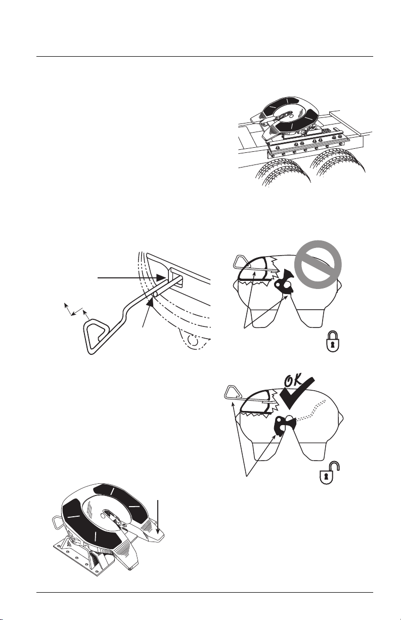
FIFTH WHEEL INSPECTIONS
1. Inspect the fifth wheel and mounting.
• Confirm that the lube plates are
in place and firmly attached.
• Tighten loose fasteners.
• Replace missing fasteners.
• Repair/replace missing, cracked or
otherwise damaged components.
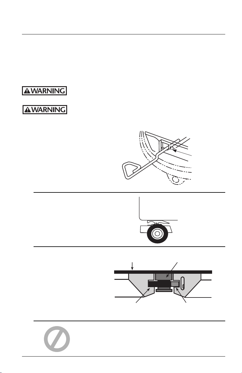
2. Make sure the lock is open. To open lock,pull secondary
k handle and hook on casting if equipped.Then pull
loc
primary release handle as shown.
3. Inspect the lock jaw; if it appears dry,
4. Tilt the ramps down.
XL-FW418-01 Rev C
apply grease to loc
k jaw and front of
throat directly,or through the lube
tube grease fitting located near the
front, left side of the fifth wheel.
LUBE
TUBE
3
OPERATING
✔
CHAMPHERED (Prefered)
or LARGE RADIUSED
LEADING EDGE
20°
2˝
min.
40˝
6˝min.
6˝min.
Keep bolts and nuts
clear of this ar
ea
Keep path of fifth
wheel free of
large holes
& gouges
✔
MAKE SURE
THERE ARE NO
SHARP EDGES
NO ABRUPT TRANSITIONS
IN ELEVATION
ACCESS
HOLE
✔
NO!
FULL
CONTACT
INSTRUCTIONS
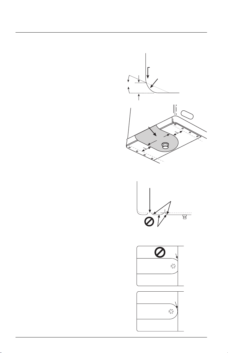
TRAILER UPPER COUPLER INSPECTIONS
1. Inspect the leading edge of the trailer
bolster/skid plate. It must be free of
any square or sharp edges.
2. Make sur
e that there are no bolts or
nuts extending below the bolster/skid
plate within 6˝ of the fifth wheel
travel path while coupling.
3. The area that is supported by the fifth
wheel should be fr
ee of any large holes
or gouges.
4. Any access holes that the fifth wheel
passes belo
w should have chamfered
or radius edges.
5. Check that any splits from the skid
plate to bolster plate ar
e welded
adequately and that there are no sharp
edges or abrupt changes in elevation.
6. The upper coupler should extend
adequatel
y rearward to maintain full
contact with the fifth wheel during
tight turning. If it does not, at a
minimum, the rear edges should be
chamfered or radius edges.
7. Make sure that any upper coupler
esidual grease is free of heavy
r
coarse grit.
8. Ensure that the upper coupler fifth
wheel contact surf
Do not paint contact area! The
ace is free of rust.
area should be conditioned with rust
inhibitor such as a light oil.
9. Inspect the kingpin for excessive wear
and damag
Kingpin Gage) along with bolster bow
(see SAE 1700).
4
e (use Holland tool TF-0110
XL-FW418-01 Rev C
OPERATING
OK
TRAILER
(TOP)
KINGPIN
INSTRUCTIONS
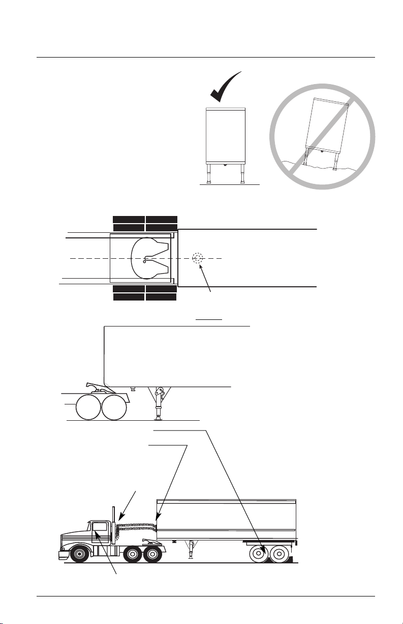
COUPLING PROCEDURES
1. Make sure coupling area is
flat, level and clear of persons
and obstacles.
2. Center fifth wheel with kingpin and back up straight.
3. Back tractor close to trailer and STOP
4. Chock tr
5. Connect brake lines
and light cord.
6. Support slac
to prevent interference.
ailer wheels.
k in lines
7. Set trailer brakes.
XL-FW418-01 Rev C
.
5
OPERATING
Wrong
FIFTH WHEEL
WILL NOT
LIFT TRAILER
BACK INTO TRAILER
SLOWLY
➠➠
OK
FIFTH WHEEL
MUST LIFT
TRAILER
➠
➠
FIFTH WHEEL
TILTED DOWN
4˝- 6˝
DO NOT
BACK INTO
TRAILER FAST
➠➠ ➠➠ ➠➠ ➠➠
➠
PULL TEST
➠
➠
PULL FORWARD WITH TRACTOR
➠
WITHOUT
PULL TEST
INSTRUCTIONS
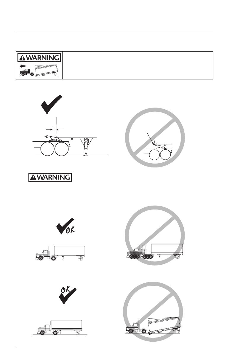
COUPLING PROCEDURES
FAILURE TO PROPERLY INSTALL, OPERATE, OR MAINTAIN THIS FIFTH
WHEEL MAY RESULT IN TRACTOR AND TRAILER SEPARATION WHICH, IF
NOT AVOIDED, COULD RESULT IN DEATH OR SERIOUS INJURY.
8. Adjust trailer height so fifth wheel will lift trailer. Trailer should
contact fifth wheel 4˝ – 6˝ behind fifth wheel bracket pin.
Attempting to couple with the trailer at an improper
allowing tractor and trailer separation which, if not avoided, could result
in death or serious injury.
9. Slowly back into trailer.
height may result in a false or improper coupling,
10. Do a pull test as an INITIAL CHECK.
6
XL-FW418-01 Rev C
OPERATING
LOCK
NOTCH
BEHIND
RIB
CHECK
RELEASE
HANDLE
➠
➠
CLOSED POSITION
➠
NO GAP!
PLUNGER
LOCK JAW
AROUND
KINGPIN
PLUNGER
VISIBLE AS
SHOWN
TRAILER BOLSTER
PLATE
KINGPIN
INSTRUCTIONS
COUPLING PROCEDURES
11. Visual Inspection.
GET OUT OF THE TRACTOR!
VISUALLY check that the lock is CLOSED!
An improperly coupled tractor and trailer may separate while
serious injur
while in use which, if not avoided, could result in death or serious injury.
If you do not obtain a proper couple, repeat the coupling sequence.
in use which, if not avoided, could result in death or
y.
Do not use any fifth wheel that fails to operate properly. Failure
to properly couple tractor and trailer may allow separation
1
✓
XL-FW418-01 Rev C
2
✓
3
✓
DO NOT
RELY ON
SOUND
7
OPERATING
SECURE
CRANK
INSTRUCTIONS
COUPLING PROCEDURES
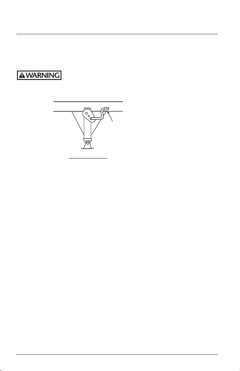
12. Follow instructions published separately for safe operation of the trailer to fully
retract landing gear and secure crank handle.
DO NOT operate the vehicle without fully retracting the
landing gear
sufficient ground clearance for transit may result in damage to the landing gear
or components which, if not avoided, could result in death or serious injury.
. Failure to fully retract the landing gear to attain
13. Re-check brake lines and light cord.Remove wheel chocks,
continue with pre-trip inspection.
8
XL-FW418-01 Rev C
 Loading...