


Owner’s Manual
Manual del propietario
FW16 Low Lube Series Fifth Wheels
Operation, Maintenance and Troubleshooting
Procedures; Warranty Information
Quinta ruedas Low Lube Serie FW16
Operación, mantenimiento y procedimientos de
resolución de problemas; información de garantía
EnglishEspañol
XL-FW10055UM-en-US Rev D

Contents
Contents Page
Introduction ..............................................2
Notes, Cautions, and Warnings ..................2
Section 1 – General Safety Instructions .....3
Section 2 – Model Identification................4
Section 3 – Decal Requirements ................4
Section 4 – Fifth Wheel Intended Use ........5
Section 5 – Fifth Wheel Non-Intended Use ...5
Section 6 – Coupling Preparation ..............5
Section 7 – Coupling Procedures ...............8
Section 8 – Uncoupling Procedures .........11
Section 9 – Positioning Sliding Fifth Wheel ...13
Section 10 – Fifth Wheel Maintenance ....14
Introduction
This manual provides the information necessary
for the proper operation and maintenance of the
HOLLAND
®
FW16 XA-161 Series Fifth Wheels.
Read this manual before using or servicing
this product and keep it in a safe location for
future reference. Updates to this manual,
which are published as necessary, are available
on the internet at www.safholland.us.
When replacement parts are required,
SAF-HOLLAND
use of only SAF-HOLLAND
A list of technical support locations that
supply SAF-HOLLAND
®
highly recommends the
®
Original Parts.
®
Original Parts and
an Aftermarket Parts Catalog are available
on the internet at www.safholland.us or
contact Customer Service at 888-396-6501.
Notes, Cautions, and Warnings
Before starting any work on the unit, read
and understand all the safety procedures
presented in this manual. This manual
contains the terms “NOTE”, “IMPORTANT”,
“CAUTION”, and “WARNING” followed by
important product information. These
terms are defined as follows:
Contents Page
Section 11 – Top Plate Removal ..............15
Section 12 – Lube Plate Inspection.......... 16
Section 13 – Fifth Wheel Lubrication .......16
Section 14 – Slide Base Lubrication..........17
Section 15 – Fifth Wheel Adjustment .......18
Section 16 – Slide Base Adjustment .........21
Section 17 – Pocket Insert Inspection ...... 22
Section 18 – Top Plate Installation...........22
Section 19 – Troubleshooting ..................23
Section 20 – Rebuild and Replacement Kits ..25
Warranty and Performance Guarantee .....26
IMPORTANT: Includes additional
information that
if not followed could
lead to hindered
product performance.
Used without the safety
alert symbol, indicates
a potentially hazardous
situation which, if not
avoided, could result in
property damage.
Indicates a potentially
hazardous situation
which, if not avoided,
could result in minor or
moderate injury.
Indicates a potentially
hazardous situation
which, if not avoided,
could result in death or
serious injury.
NOTE: Includes additional information
to enable accurate and easy
performance of procedures.
2
XL-FW10055UM-en-US Rev D · 2014-01-29 · Amendments and Errors Reserved · © SAF-HOLLAND, Inc., SAF-HOLLAND, HOLLAND, SAF,
and logos are trademarks of SAF-HOLLAND S.A., SAF-HOLLAND GmbH, and SAF-HOLLAND, Inc.

1. General Safety Instructions
Read and observe all Warning and Caution
hazard alert messages. The alerts provide
information that can help prevent serious
personal injury, damage to components,
or both.
Failure to follow the instructions
and safety precautions in
this manual could result
in improper servicing or
operation leading to
component failure which,
if not avoided, could result
in death or serious injury.
All fifth wheel installation and maintenance
MUST be performed by a properly
technician using proper/special tools, and
safe procedures.
NOTE: In the United States, workshop
safety requirements are defined by
federal and/or state Occupational
Safety and Health Act (OSHA).
Equivalent laws could exist in
other countries. This manual is
written based on the assumption
that OSHA or other applicable
employee safety regulations are
followed by the location where
work is performed.
IMPORTANT: Prior to operation of the
fifth wheel, verify that
the fifth wheel has been
appropriately installed
on the vehicle.
trained
Model Identification
IMPORTANT: These instructions apply
to the proper operation of
the FW16 XA-161 Series
Fifth Wheel top plates only.
There are other important
checks, inspections, and
procedures not listed here
that are necessary, prudent,
and/or required by law.
For proper installation procedures, refer
to Installation Manual XL-FW10008BM
available on the internet at www.safholland.us.
Failure to follow all the
operating procedures
contained in these
instructions could result
in a hazardous condition
or cause a hazardous
condition to develop
which, if not avoided,
could result in death or
serious injury.
English
Failure to properly install the
fifth wheel could result in
tractor-trailer separation
which, if not avoided,
could result in death or
serious injury.
XL-FW10055UM-en-US Rev D · 2014-01-29 · Amendments and Errors Reserved · © SAF-HOLLAND, Inc., SAF-HOLLAND, HOLLAND, SAF,
and logos are trademarks of SAF-HOLLAND S.A., SAF-HOLLAND GmbH, and SAF-HOLLAND, Inc.
3

General Safety Instructions
2. Model Identification
Fifth wheel serial tags are located on the left
side of the fifth wheel top plate above the
fifth wheel bracket pin, or on the pickup
ramps (Figure 1).
The part number and serial number are
listed on the tag (Figure 2).
3. Decal Requirements
Decal XL-FW20001DC-en-US (Figure 3)
enclosed in plastic bag with the Owner’s
Manual, MUST be installed near the fifth
wheel and easily viewed by the operator.
Position the decal as illustrated (Figure 4).
NOTE: Make sure surface is free of oil
It is the responsibility of the end user to
periodically inspect the decal and ensure
that it is clean and completely legible. If
the label is missing, loose, damaged or
difficult to read, contact SAF-HOLLAND
Customer Service at 888-396-6501 to
order replacements immediately.
and grease before applying decal.
®
Figure 1
Figure 2
Model No. XXXXXXXXXXXXXXXXXX
Serial No. XXXXXXXXXXXXXXXXXX
U.S. AND FOREIGN PATENTS APPLY
MADE IN
FAILURE TO PROPERLY INSTALL, MAINTAIN & OPERATE
THIS PRODUCT COULD RESULT IN TRACTOR TRAILER
SEPARATION CAUSING SERIOUS INJURY OR DEATH.
XXXXXX
Figure 3
WARNING / ADVERTENCIA
ALWAYS inspect fifth wheel after coupling tractor to trailer.
Failure to properly couple the tractor and trailer could result in tractor-trailer separation while in use
which, if not avoided, could result in death or serious injury.
SIEMPRE inspeccione la quinta rueda después de acoplar el tractocamión al remolque.
Si no acopla adecuadamente el tractocamión y el remolque, podría ocasionar la separación del tractocamión
y el remolque durante el uso, lo cual, si no se evita, puede causar muertes o lesiones.
CORRECT COUPLING / ACOPLAMIENTO CORRECTO
1.
Lock notch
behind rib.
Muesca de cierre
detrás del reborde.
2.
Sin separación
No gap
3.
Lock completely closed around kingpin.
Seguro completamente cerrado alrededor
del perno rey.
Copyright © 2014 $SAF-HOLLAND, Inc.
www.safholland.us XL-FW20001DC-en-US
Figure 4
WARNING / ADVERTENCIA
ALWAYS inspect fifth wheel after coupling tractor to trailer.
Failure to properly couple the tractor and trailer could result in tractor-trailer separation while in use
which, if not avoided, could result in death or serious injury.
SIEMPRE inspeccione la quinta rueda después de acoplar el tractocamión al remolque.
Si no acopla adecuadamente el tractocamión y el remolque, podría ocasionar la separación del tractocamión
y el remolque durante el uso, lo cual, si no se evita, puede causar muertes o lesiones.
CORRECT COUPLING / ACOPLAMIENTO CORRECTO
3.
Lock completely closed around kingpin.
1.
Lock notch
2.
No gap
behind rib.
Seguro completamente cerrado alrededor
Sin separación
del perno rey.
Muesca de cierre
detrás del reborde.
Copyright © 2014 $SAF-HOLLAND, Inc.
www.safholland.us XL-FW20001DC-en-US
4
XL-FW10055UM-en-US Rev D · 2014-01-29 · Amendments and Errors Reserved · © SAF-HOLLAND, Inc., SAF-HOLLAND, HOLLAND, SAF,
and logos are trademarks of SAF-HOLLAND S.A., SAF-HOLLAND GmbH, and SAF-HOLLAND, Inc.
Operation Instructions
4. Fifth Wheel Intended Use
1. Pulling trailers with standard SAE
kingpins which are in good condition
and securely mounted or locked in
position in the trailer.
2. Transporting loads that are within the
maximum fifth wheel rated capacities:
50,000 lbs. (22,680 kg) Maximum
Vertical Load 150,000 lbs. (68,040 kg)
Maximum Drawbar Pull.
3. In on-road applications.
IMPORTANT: SAF-HOLLAND
®
definition
of off-road refers to
terrain on which a tractortrailer operates which is
unpaved and rough, or
ungraded. Any terrain not
considered part of the
public highway system
falls under this heading.
4. As recommended in SAF-HOLLAND
®
literature available on the Internet at
www.safholland.us.
5. Fifth Wheel
Non-Intended Use
1. Operating with a non-SAE compliant
kingpin, such as kingpins which are bent,
improper size or dimensions, not secured
to maintain SAE configuration, or which
are installed in warped trailer bolster
plates, or upper coupler and fifth wheel
lube plates that DO NOT maintain the SAE
kingpin dimensions. Refer to SAF-HOLLAND®
Service Bulletin XL-SB004-01 (available on
the Internet at www.safholland.us) for more
information on fifth wheel lube plates.
Failure to couple with a SAE
compliant kingpin could
result in improper coupling,
allowing tractor-trailer
separation, which if not
avoided, could result in
death or serious injury.
2. Tow-away operations which damage
or interfere with the proper operation
of the fifth wheel.
3. The attachment of lifting devices.
4. The transport of loads in excess of
rated capacity.
5. In off-road applications.
6. Applications other than those
recommended in SAF-HOLLAND
®
literature available on the Internet
at www.safholland.us.
6. Coupling Preparation
1. Prior to coupling, inspect the fifth
wheel and mounting. Perform and
verify the following:
Confirm that lube plates are in place
and firmly fastened.
Tighten loose fasteners.
Replace missing fasteners.
Repair/replace missing, cracked or
otherwise damaged components.
Inspect fifth wheel mechanism.
Lubricate dry or rusty components.
For a sliding fifth wheel, make sure
both plungers are fully engaged.
Inspect air line connections.
Make sure fifth wheel is in appropriate
position for weight distribution on the
tractor. For proper positioning of the
fifth wheel, refer to SAF-HOLLAND
publication XL-FW10008BM available
on the Internet at www.safholland.us.
2. Make sure coupling area is flat, level,
and clear of persons and obstacles.
English
®
XL-FW10055UM-en-US Rev D · 2014-01-29 · Amendments and Errors Reserved · © SAF-HOLLAND, Inc., SAF-HOLLAND, HOLLAND, SAF,
and logos are trademarks of SAF-HOLLAND S.A., SAF-HOLLAND GmbH, and SAF-HOLLAND, Inc.
5

Operation Instructions
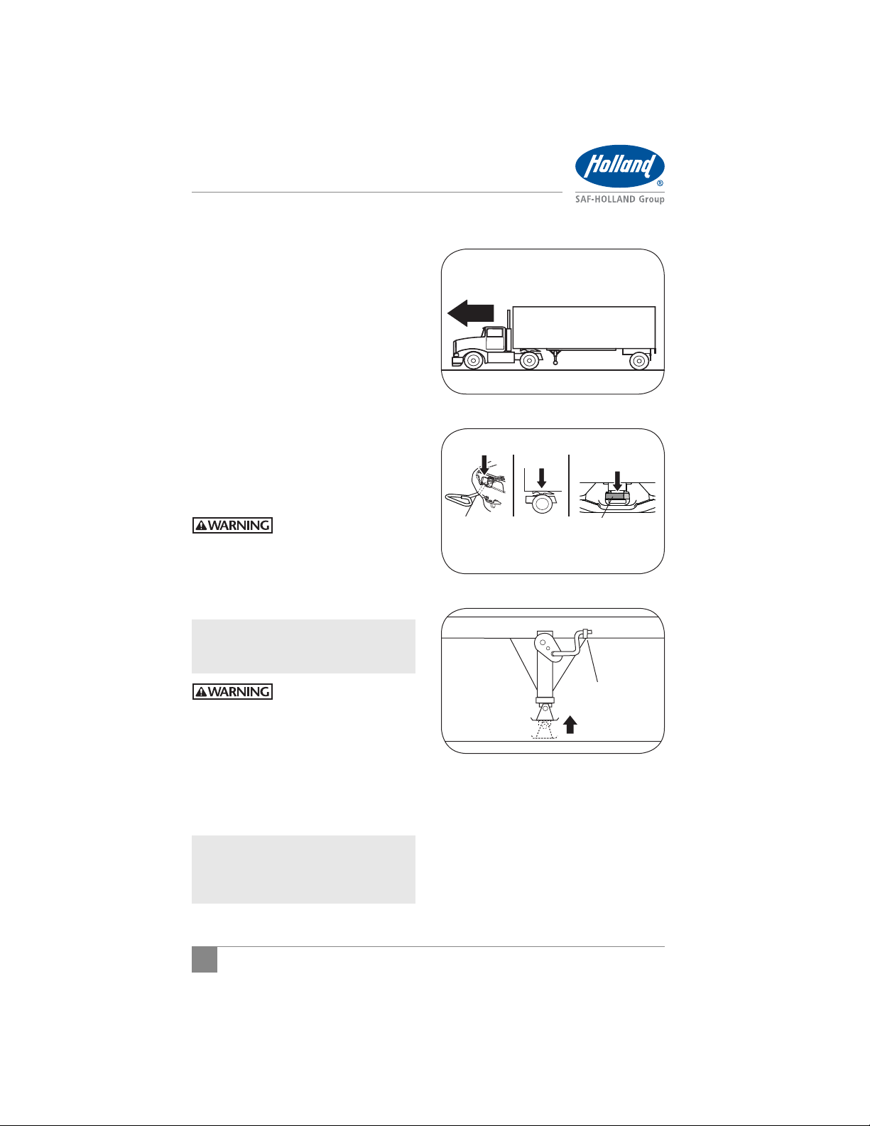
3. Tilt ramps of fifth wheel downward
(Figure 5).
4. Make sure locks are open (Figure 6). If
locks are closed, slide release handle to
the left and pull all the way out (Figure
7). Pry locks open with lever bar.
5. Inspect leading edge of trailer bolster/skid
plate. It MUST be free of any square or
sharp edges (Figure 8).
6. Make sure there are no bolts or nuts
extending below bolster/skid plate
within 152 mm (6.0") of the fifth
wheel travel path while coupling.
Figure 5
TILT DOWNWARDTILT DOWNWARD
Figure 6
LOCK IS OPEN LOCK IS CLOSED
Figure 7
LEFT HAND RELEASE RIGHT HAND RELEASE
Figure 8
CHAMFERED (Preferred)
OR LARGE RADIUS
LEADING EDGE
20º
2"
MINIMUM
6
XL-FW10055UM-en-US Rev D · 2014-01-29 · Amendments and Errors Reserved · © SAF-HOLLAND, Inc., SAF-HOLLAND, HOLLAND, SAF,
and logos are trademarks of SAF-HOLLAND S.A., SAF-HOLLAND GmbH, and SAF-HOLLAND, Inc.

Operation Instructions
should be free of any large holes or
gouges (Figure 9).
8. Any access holes that the fifth wheel
passes beneath should have chamfered
or radius edges.
9. Check that any splits from the skid
plate to bolster plate are welded
adequately, and that there are no
sharp edges or abrupt changes in
elevation (Figure 10).
10. The upper coupler should extend
adequately rearward to maintain full
contact with the fifth wheel during
tight turning. If it does not, at a
minimum, the rear edges should be
chamfered or radius edges.
11. Make sure that any upper coupler residual
grease is free of heavy course grit.
12. Ensure that the upper coupler fifth
wheel contact surface is free of rust
and is not painted. The area should be
conditioned with a rust inhibitor such
as a light oil.
13. Verify that kingpin is not obstructed by
a kingpin lock or other security device.
Failure to remove kingpin
lock prior to coupling
could result in improper
coupling which, if not
avoided, could result in
death or serious injury.
14. Inspect kingpin for excessive wear
and damage (use HOLLAND
Gage tool TF-0110 ) along with bolster
plate bow (See SAF-HOLLAND
®
Kingpin
®
Service
Bulletins XL-SB020 and XL-SB033).
Figure 97. The area supported by the fifth wheel
KEEP PATH OF FIFTH WHEEL FREE
OF LARGE HOLES AND GOUGES
6" MIN.
40"
6" MIN.
KEEP BOLTS AND
NUTS CLEAR OF
THIS AREA
Figure 10
ACCESS HOLE
MAKE SURE THERE ARE
NO SHARP EDGES
NO ABRUPT TRANSITIONS IN ELEVATION
English
XL-FW10055UM-en-US Rev D · 2014-01-29 · Amendments and Errors Reserved · © SAF-HOLLAND, Inc., SAF-HOLLAND, HOLLAND, SAF,
and logos are trademarks of SAF-HOLLAND S.A., SAF-HOLLAND GmbH, and SAF-HOLLAND, Inc.
7

Operation Instructions
7. Coupling Procedures
IMPORTANT: Following proper coupling
procedures for FW16
Low Lube fifth wheels
is extremely important.
Failure to follow all of the
procedures contained in
these coupling instructions
could result in damage to
the lube plates.
1. Chock trailer wheels.
2. Position the tractor so the center of the
fifth wheel is aligned with the kingpin.
3. Traveling in a straight line, slowly
back tractor to trailer. STOP the tractor
before making contact with the trailer
(Figure 11).
IMPORTANT: DO NOT make contact
between fifth wheel and
trailer or damage to lube
plates could occur.
4. Set tractor parking brake and place
into neutral.
5. Completely exhaust air from tractor
suspension, ensuring that the fifth
wheel is below the contact surface
of trailer (Figure 12).
6. Exit the cab and make sure the fifth
wheel is below the upper coupler plate.
Verify proper fifth wheel height. If
trailer is too low, use landing gear to
raise the trailer height.
Figure 11
TRAILER
(TOP)
KINGPIN
Figure 12
EXHAUST SUSPENSION AIR
BEFORE BACKING UP
NOTE: For proper operation of landing
gear, follow the instructions
published by the landing
gear manufacturer.
8
XL-FW10055UM-en-US Rev D · 2014-01-29 · Amendments and Errors Reserved · © SAF-HOLLAND, Inc., SAF-HOLLAND, HOLLAND, SAF,
and logos are trademarks of SAF-HOLLAND S.A., SAF-HOLLAND GmbH, and SAF-HOLLAND, Inc.

Operation Instructions
7. Slowly back up, using lowest gear
possible. Stop when fifth wheel is
under the leading edge of the trailer
(Figure 13).
8. Set tractor parking brake. Place in
neutral. Exit cab and verify proper fifth
wheel to kingpin alignment.
9. Adjust tractor suspension to ride height.
The fifth wheel plate face MUST make
contact with the upper coupler plate
(Figure 14). If fifth wheel does not
make contact with the upper coupler
plate, use the landing gear to lower the
trailer until fifth wheel makes contact.
IMPORTANT: If trailer is too high the
kingpin will not properly
connect with the lock jaw.
Failure to couple with the
trailer at the proper height
could result in improper
coupling, allowing tractor
and trailer separation,
which if not avoided,
could result in death or
serious injury.
IMPORTANT: NEVER inflate the tractor
suspension when the
kingpin is above the
throat of the fifth wheel.
Figure 13
BACK UP
AND STOP!
Figure 14
English
Failure to avoid inflating
tractor suspension when
the fifth wheel is not
forward of the king pin,
could result in damage to
the kingpin and fifth wheel.
10. Slowly back into the trailer, engaging
kingpin in the fifth wheel.
11. Connect the air and electrical lines.
12. Raise the landing gear legs until the
pads are just above the ground.
XL-FW10055UM-en-US Rev D · 2014-01-29 · Amendments and Errors Reserved · © SAF-HOLLAND, Inc., SAF-HOLLAND, HOLLAND, SAF,
and logos are trademarks of SAF-HOLLAND S.A., SAF-HOLLAND GmbH, and SAF-HOLLAND, Inc.
9
Operation Instructions
13. Perform a pull test as an INITIAL CHECK
by locking the trailer brakes and pulling
forward with the tractor to make sure
that tractor-trailer separation does not
occur (Figure 15).
14. Set the tractor parking brake.
15. Exit the cab and visually inspect for
the following to ensure that the lock
is closed (Figure 16).
a. Release handle fully retracted with
lock notch behind rib.
b. No gap is permissible between the
trailer upper coupler plate and the
fifth wheel.
c. Lock securely closed behind jaw.
16. If proper coupling has NOT been achieved,
repeat the coupling procedure.
Failure to properly couple
the tractor and trailer could
result in tractor-trailer
separation while in use
which, if not avoided,
could result in death or
serious injury.
IMPORTANT: DO NOT use any fifth
wheel that fails to
operate properly.
Figure 15
LOCK TRAILER BRAKES AND
PULL FORWARD WITH TRAILER
Figure 16
NO GAP!
LOCK NOTCH
BEHIND RIB
Figure 17
LOCKS COMPLETELY
CLOSED AROUND
KINGPIN
Failure to repair a
malfunctioning fifth
wheel before use could
result in tractor-trailer
separation which, if not
avoided, could result in
death or serious injury.
17. Fully retract the landing gear legs
off the ground and secure the crank
handle (Figure 17).
NOTE: For proper operation of landing
gear, follow the instructions
published by the landing
gear manufacturer.
18. Remove the wheel chocks and continue
with the pre-trip inspection.
10
XL-FW10055UM-en-US Rev D · 2014-01-29 · Amendments and Errors Reserved · © SAF-HOLLAND, Inc., SAF-HOLLAND, HOLLAND, SAF,
and logos are trademarks of SAF-HOLLAND S.A., SAF-HOLLAND GmbH, and SAF-HOLLAND, Inc.
SECURE
CRANK

Operation Instructions
8. Uncoupling Procedures
IMPORTANT: Following proper
uncoupling procedures
FW16 Low Lube fifth wheels
is extremely important.
Failure to follow all of the
procedures contained in
these uncoupling instructions
could result in damage to
the lube plates.
1. Position the tractor and trailer, in straight
alignment, on firm, level ground clear
of obstacles and persons.
2. Set the trailer brakes.
3. Slowly back the tractor tightly against
the trailer to relieve pressure on the
fifth wheel locks.
4. Set the tractor parking brake.
IMPORTANT: DO NOT exhaust air
from tractor suspension
before uncoupling.
Failure to avoid exhausting
tractor suspension before
uncoupling could result
in difficulty uncoupling
tractor from trailer which,
if not avoided, could
result in damage to the
fifth wheel and kingpin.
5. Chock the trailer wheels.
6. Lower the landing gear until the pads
just touch the ground (Figure 18).
NOTE: For proper operation and ability
to transfer trailer weight from
the fifth wheel, follow the landing
gear manufacturer’s published
instructions. DO NOT raise
trailer off of the fifth wheel.
Figure 18
LOWER LANDING GEAR
English
XL-FW10055UM-en-US Rev D · 2014-01-29 · Amendments and Errors Reserved · © SAF-HOLLAND, Inc., SAF-HOLLAND, HOLLAND, SAF,
and logos are trademarks of SAF-HOLLAND S.A., SAF-HOLLAND GmbH, and SAF-HOLLAND, Inc.
11

Operation Instructions
7. Disconnect the air and electrical lines
from the trailer and secure to tractor.
8. Slide release handle to the left, pull all
the way out, slide handle left and hook
on casting handle (Figure 19).
9. Release the tractor parking brake and
slowly pull forward 12"-18" (306-457 mm)
to disengage kingpin from fifth wheel.
Fifth wheel should be between the front
edge of trailer and kingpin (Figure 20).
IMPORTANT: DO NOT drive the tractor
free of the trailer.
10. Set the tractor parking brake and place
into neutral. Completely exhaust air
from tractor suspension, ensuring that
the fifth wheel is below the contact
surface of trailer (Figure 21).
11. Visually inspect uncoupling. Make sure
the trailer is completely supported by
the landing gear.
12. Release the tractor parking brake and
slowly pull away from the trailer.
13. Apply air to the tractor air suspension
and allow suspension to return to ride
height (Figure 22).
Figure 19
LEFT HAND RELEASE RIGHT HAND RELEASE
Figure 20
SLOWLY PULL FORWARD
AND STOP
Figure 21
EXHAUST SUSPENSION AIR
BEFORE PULLING FORWARD
12
Figure 22
RETURN TRACTOR SUSPENSION
TO RIDE HEIGHT
XL-FW10055UM-en-US Rev D · 2014-01-29 · Amendments and Errors Reserved · © SAF-HOLLAND, Inc., SAF-HOLLAND, HOLLAND, SAF,
and logos are trademarks of SAF-HOLLAND S.A., SAF-HOLLAND GmbH, and SAF-HOLLAND, Inc.

Operation Instructions
9. Positioning Sliding
Fifth Wheels
1. Position the tractor and trailer, in straight
alignment, on firm, level ground clear
of obstacles and persons.
2. Set tractor and trailer parking brakes,
place tractor in neutral.
Failure to stop and properly
lock the tractor and
trailer brakes could cause
uncontrolled sliding of
fifth wheel which, if not
avoided, could result in
component damage to
tractor or trailer.
3. Release slide locking plungers by
moving cab switch to unlock position
(Figure 23). If manual slide release
equipped, pull release lever. If plungers
DO NOT come out, lower the landing
gear to relieve pressure on the fifth
wheel. This will allow fifth wheel to
slide easier.
NOTE: Cab switch style could differ
by OEM.
4. Visually inspect and verify that
plungers are disengaged.
5. Release tractor parking brake while
keeping trailer brakes engaged.
6. Slowly drive the tractor forward or
backward to position fifth wheel. Stop
tractor at desired position.
7. Re-engage slide locking plungers by
moving cab switch to the lock position
(Figure 24). If manual slide release
equipped, pull release arm to allow
plungers to retract.
8. Place tractor in neutral, set tractor
parking brake.
Figure 23
AIR OPERATED
MOVE CAB SWITCH TO
UNLOCK POSITION
Figure 24
AIR OPERATED
MOVE CAB SWITCH
TO LOCK POSITION
English
XL-FW10055UM-en-US Rev D · 2014-01-29 · Amendments and Errors Reserved · © SAF-HOLLAND, Inc., SAF-HOLLAND, HOLLAND, SAF,
and logos are trademarks of SAF-HOLLAND S.A., SAF-HOLLAND GmbH, and SAF-HOLLAND, Inc.
13

Maintenance Procedures
9. Visually inspect plunger lock bars to
ensure proper engagement (Figure 25).
10. Retract landing gear legs, if lowered.
11. Verify that slide locking plungers have
been re-engaged by performing a pull
test (Figure 26).
IMPORTANT: DO NOT operate the
vehicle if the plungers are
not fully engaged (locked).
Failure to properly engage
plungers and slide base
could cause loss of vehicle
control which, if not
avoided, could result in
death or serious injury.
10. Fifth Wheel Maintenance
IMPORTANT: All maintenance MUST be
performed by a properly
trained technician using
proper tools and safe
procedures.
IMPORTANT: All maintenance MUST
be performed while the
tractor is uncoupled
from the trailer.
Failure to properly maintain
the fifth wheel could
result in tractor-trailer
separation which, if not
avoided, could result in
death or serious injury.
Figure 25
LOCKED
(ENGAGED)
RACK
PLUNGER
TRADITIONAL SLIDERS
Figure 26
LOCK TRAILER BRAKES AND
PULL FORWARD WITH TRAILER
NOTE: Removal of the fifth wheel
top plate is not required for
maintenance but could be required
when performing repairs.
1. Thoroughly clean the locking mechanism
every six (6) months or 60,000 miles.
2. Prior to coupling, inspect the fifth
wheel and mounting. Perform and
verify the following:
Confirm that lube plates are in place
and firmly fastened.
14
XL-FW10055UM-en-US Rev D · 2014-01-29 · Amendments and Errors Reserved · © SAF-HOLLAND, Inc., SAF-HOLLAND, HOLLAND, SAF,
and logos are trademarks of SAF-HOLLAND S.A., SAF-HOLLAND GmbH, and SAF-HOLLAND, Inc.

Maintenance Procedures
Tighten loose fasteners.
Replace missing fasteners.
Repair/replace missing, cracked or
otherwise damaged components.
Inspect fifth wheel mechanism.
Lubricate dry or rusty components.
For a sliding fifth wheel, make sure
both plungers are fully engaged.
Inspect air line connections.
Make sure fifth wheel is in appropriate
position for weight distribution on the
tractor. For proper positioning of the
fifth wheel, refer to SAF-HOLLAND
®
publication XL-FW10008BM available
on the Internet at www.safholland.us.
11. Top Plate Removal
IMPORTANT: Fifth wheel assembly
1. Remove bracket pin retention nuts and
bolts from both sides of fifth wheel top
plate (Figure 27).
2. Using a pry bar, pull bracket retention pins
out of fifth wheel top plate (Figure 27).
3. Using a lifting device capable of lifting
500 lbs. (227 kg), remove the top plate
from the mounting base. Place fifth
wheel on a flat, clean working area.
has replaceable pocket
inserts installed between
the fifth wheel top plate
and mounting base.
When removing top
plate, be careful not
to lose pocket inserts.
Failure to prevent pocket
inserts from falling out of
the top plate could cause
a potentially hazardous
situation which, if not
avoided, could result in
minor or moderate injury.
Figure 27
TOP PLATE
RETENTION BOLT
BRACKET PIN
RETENTION NUT
English
NOTE: Follow instructions published by
lifting device manufacturer for
proper operation of lifting device.
XL-FW10055UM-en-US Rev D · 2014-01-29 · Amendments and Errors Reserved · © SAF-HOLLAND, Inc., SAF-HOLLAND, HOLLAND, SAF,
and logos are trademarks of SAF-HOLLAND S.A., SAF-HOLLAND GmbH, and SAF-HOLLAND, Inc.
15

Maintenance Procedures
12. Lube Plate Inspection
Thoroughly steam clean top surface of fifth
wheel for visual inspection. Replace lube
plates if:
One or both lube plates is missing.
A straight edge laid across the lube
plate contacts any metal portion of the
fifth wheel surrounding the lube plates
(Figure 28).
Lube plates are severely chipped, worn,
cracked, gouged or bent
20% (40 sq. in.) or more of lube plate
coating is missing from one or both
plates due to normal wear or damage.
13. Fifth Wheel Lubrication
IMPORTANT: Fifth wheel lubrication
is necessary to get the
maximum service life
from the FW16 series
fifth wheel. Perform the
following procedures at
the intervals listed.
Figure 28
LOOK FOR
STRAIGHT EDGE
CONTACT HERE
FW16 series fifth wheels are equipped with
NoLube plate inserts that eliminate the
need to lubricate the fifth wheel-to-trailer
contact surfaces.
FW16 series fifth wheels are equipped
with a lube tube that provides grease to the
locking mechanism using a grease fitting.
Lubricate locking mechanism every three
(3) months or 30,000 miles.
Thoroughly clean the locking mechanism
every six (6) months or 60,000 miles.
16
XL-FW10055UM-en-US Rev D · 2014-01-29 · Amendments and Errors Reserved · © SAF-HOLLAND, Inc., SAF-HOLLAND, HOLLAND, SAF,
and logos are trademarks of SAF-HOLLAND S.A., SAF-HOLLAND GmbH, and SAF-HOLLAND, Inc.

Maintenance Procedures
IMPORTANT:
Fifth wheels that operate
in snowy or icy winter
conditions, lubrication
should be performed
every spring in addition
to routine lubrication
(as noted on the previous
page) to ensure
optimum operation.
13.A Proper Lubrication Method
Using water-resistant lithium-based
1.
grease,
lubricate (A) swing lock-to-hook
contact areas directly or through the lube
tube grease fitting, and (B) camtrack
(Figure 29).
2. Using a light oil, lubricate (C) hook pin,
and (D) release handle pivot (Figure 29).
13.B As-Needed Lubrication
Clean and lubricate locking mechanism
if operational difficulties (i.e. problems
with coupling, uncoupling, or pulling the
release handle) arise during the service
life of the fifth wheel (Figure 29).
14. Slide Base Lubrication
NOTE: Slide base should be moved fore
IMPORTANT: If equipped with air
1. With the piston shaft in the exposed
ILS Sliders: Spray spring covered piston
and aft at least once a year to
maintain optimum performance.
release, lubricate air
cylinder every three (3)
months or 30,000 miles
whichever comes first.
position, clean with penetrating oil
and a clean shop towel (Figure 30).
shaft thoroughly with penetrating oil
(Figure 31).
Figure 29
D
B
C
Figure 30
Figure 31
ILS SLIDER
PISTON
SHAFT
LUBE TUBE GREASE FITTING
A
PISTON
SHAFT
TRADITIONAL SLIDERS
English
IMPORTANT: DO NOT use any abrasives
on the exposed shaft as
they could damage the
piston shaft.
XL-FW10055UM-en-US Rev D · 2014-01-29 · Amendments and Errors Reserved · © SAF-HOLLAND, Inc., SAF-HOLLAND, HOLLAND, SAF,
and logos are trademarks of SAF-HOLLAND S.A., SAF-HOLLAND GmbH, and SAF-HOLLAND, Inc.
17

Maintenance Procedures
2. Remove supply air line and add 2-4 drops
of air tool oil to cylinder through the
supply fitting. Re-install supply air line
(Figures 32 and 33 - Traditional
Sliders, Figure 34- ILS Sliders).
3. Activate and de-activate air cylinder
2-3 times to work air tool oil into
cylinder and onto piston and verify
proper operation.
15. Fifth Wheel Adjustment
Fifth wheel adjustment should be performed
at a minimum of every 60,000 miles or if
excessive movement between kingpin and
fifth wheel is noticed when driving the vehicle.
IMPORTANT: Excessive movement
between the tractor
and trailer can effect
vehicle handling.
Failure to maintain proper
fifth wheel adjustment
could result in loss of
vehicle control which, if
not avoided, could result
in death or serious injury.
Figure 32
TRADITIONAL SLIDER
SUPPLY FITTING
Figure 33
SUPPLY FITTING
TRADITIONAL SLIDER
Figure 34
ILS SLIDER
NOTE: To obtain proper adjustment
SAF-HOLLAND
use of HOLLAND
Part No. TF-TLN-5001, available
from a local HOLLAND
®
recommends
®
lock tester
®
distributor.
1. If fifth wheel is locked, slide release
handle to the left and pull all the way
out (Figure 35). Pry locks open with
lever bar.
2.
Set lock tester on fifth wheel top plate .
18
XL-FW10055UM-en-US Rev D · 2014-01-29 · Amendments and Errors Reserved · © SAF-HOLLAND, Inc., SAF-HOLLAND, HOLLAND, SAF,
PISTON
SHAFT
Figure 35
LEFT HAND RELEASE RIGHT HAND RELEASE
and logos are trademarks of SAF-HOLLAND S.A., SAF-HOLLAND GmbH, and SAF-HOLLAND, Inc.

Maintenance Procedures
3. To lock fifth wheel, rotate handle on
lock tester clockwise until the locks
close around the kingpin (Figure 36).
4. Slide the lock tester forward and
backward in the closed lock to check
for play between lock and kingpin.
Ensure that the tool remains flat with
full contact on the fifth wheel top plate.
Use pin gage to measure free play. If
free play exceeds 0.080" (2.03 mm).
adjust lock mechanism (Figure 37).
5. To adjust lock, remove the low head
socket cap screw. Rotate adjusting pin
counter-clockwise (left hand release), or
clockwise (right hand release), until the
next notch lines up with the low head
socket cap screw tapped hole. Replace
the low head socket cap screw. Adjust
only one notch at a time (Figure 38).
6. Verify the proper adjustment by locking
and unlocking fifth wheel several times
with lock tester. Check that fifth wheel
is properly locked (Figure 39).
NOTE: To unlock fifth wheel, push
down on lock tester, and rotate
“J” hook under the fifth wheel,
then pull handle back.
Figure 36
Figure 37
Figure 38
FIRST NOTCH
FIRST NOTCH
English
LOW HEAD
SOCKET
CAP SCREW
LEFT HAND RIGHT HAND
Figure 39
LOCK NOTCH
BEHIND RIB
XL-FW10055UM-en-US Rev D · 2014-01-29 · Amendments and Errors Reserved · © SAF-HOLLAND, Inc., SAF-HOLLAND, HOLLAND, SAF,
and logos are trademarks of SAF-HOLLAND S.A., SAF-HOLLAND GmbH, and SAF-HOLLAND, Inc.
LOW HEAD
SOCKET
CAP SCREW
LOCK COMPLETELY
CLOSED AROUND
KINGPIN
19

Maintenance Procedures
7. Rotate lock tester from side-to-side to
ensure that lock is not overtightened.
Lock should not grip kingpin and the
tool should rotate freely (Figure 40).
8. Disengage lock tester J-Hook from
front skirt of casting and re-check for
free play in lock by sliding lock tester
forward and backward using pin gage
to measure free play (Figure 40).
Free play should be 0.040" (1.02 mm)
minimum. If free play still exceeds
0.080" (2.03 mm) repeat procedure
and adjust one more notch.
NOTE: If there is still excessive free
play in the locks with the
adjusting pin on the last (third)
notch, then the fifth wheel
should be rebuilt using the
appropriate SAF-HOLLAND
®
service kit.
Figure 40
20
XL-FW10055UM-en-US Rev D · 2014-01-29 · Amendments and Errors Reserved · © SAF-HOLLAND, Inc., SAF-HOLLAND, HOLLAND, SAF,
and logos are trademarks of SAF-HOLLAND S.A., SAF-HOLLAND GmbH, and SAF-HOLLAND, Inc.

Maintenance Procedures
16. Slide Base Adjustment
NOTE: ILS slider locking plungers
Some HOLLAND
adjustable locking plungers. Adjustment should
be performed at a minimum of every 60,000
miles or if excessive movement is noticed
when driving the vehicle. To obtain proper
adjustment, follow the following procedures:
1. Loosen lock nut and turn adjustment
2. Disengage and engage locking plungers.
3. Tighten adjustment bolt until it contacts
4. Turn adjustment bolt clockwise an
If locking plungers DO NOT release fully to
allow fifth wheel to slide:
a. Check the air cylinder for proper
b. Check locking plunger adjustment as
c. If a locking plunger is binding in the
NOTE: If problems persists, contact
DO NOT require adjustment.
®
slide bases are equipped with
bolt counterclockwise (Figure 41).
Verify that locking plungers have engaged
properly (Figures 42 and 43).
the rack.
additional 1/2 turn, then tighten lock
nut securely.
operation. Replace if necessary.
explained above.
plunger pocket, remove the locking
plunger using a HOLLAND
®
TF-TLN-2500
spring compressor. Grind the top edges
of the locking plunger 1/16" (1.5 mm)
(Figure 44). Re-install and adjust the
locking plungers as explained above.
SAF-HOLLAND
®
Customer Service
at 888-396-6501.
Figure 41
LOCK NUT
ADJUSTMENT BOLT
Figure 42
UNLOCKED
(RELEASED)
RACK
PLUNGER
Figure 43
LOCKED
(ENGAGED)
RACK
PLUNGER
Figure 44
CHECK FOR POSSIBLE INTERFERENCE
PLUNGER
English
XL-FW10055UM-en-US Rev D · 2014-01-29 · Amendments and Errors Reserved · © SAF-HOLLAND, Inc., SAF-HOLLAND, HOLLAND, SAF,
and logos are trademarks of SAF-HOLLAND S.A., SAF-HOLLAND GmbH, and SAF-HOLLAND, Inc.
1/16"
(1.5 mm)
21

Maintenance Procedures
17. Pocket Insert Inspection
Replace pocket inserts if:
The pocket insert thickness is 1/16"
(1.5 mm) or less.
The free vertical movement of top plate
on the bracket is 1/2" (12.7 mm) or
greater, without compressing rubber
bushings (Figure 45).
The pocket inserts are severely
chipped, cracked or gouged.
18. Top Plate Installation
1. If pocket inserts are dislodged from fifth
wheel casting, clean pocket area of
casting and apply a strip of double-face
tape in bottom of pockets. Install pocket
inserts by pressing down into pockets
(Figure 46).
2. Using a lifting device capable of lifting
500 lbs. (227 kg), install the fifth wheel
top plate onto its mounting base.
NOTE: Follow instructions published by
lifting device manufacturer for
proper operation of lifting device.
3. Install bracket pins through fifth wheel
casting and mounting base and secure
by installing the bracket pin retention
bolts and nuts (Figure 47). Torque
retention fasteners to 50-60 ft.-lbs.
/tN
Figure 45
REPLACE IF
1/16" (1.5 mm)
OR LESS
1/2" (12.7 mm) MAX. (MEASURED AT EAR)
PUSH DOWN
Figure 46
DOUBLE-FACE TAPE
POCKET
INSERT
POCKET
AREA
Figure 47
TOP PLATE
RETENTION BOLT
RETENTION NUT
BRACKET PIN
22
XL-FW10055UM-en-US Rev D · 2014-01-29 · Amendments and Errors Reserved · © SAF-HOLLAND, Inc., SAF-HOLLAND, HOLLAND, SAF,
and logos are trademarks of SAF-HOLLAND S.A., SAF-HOLLAND GmbH, and SAF-HOLLAND, Inc.

Troubleshooting
19. Troubleshooting
Difficult to Couple to Trailer:
9
POSSIBLE CAUSE
Attempting to couple too fast. Couple in accordance with the procedure in Section 7.
The trailer could be too high; the kingpin
is not entering the locks properly.
Lower the trailer in accordance with manufacturer's
instructions.
Lock is closed. Manually pull the release handle out as far as possible. Lock
will swing open.
Accumulated rust or grime interfering with
the lock operation.
Thoroughly clean the fifth wheel and re-lubricate in
accordance with the procedure in Section 13.
The locks are adjusted too tightly. Check lock adjustments in accordance with the procedure
in Section 15.
The locks could be damaged. The fifth wheel MUST be rebuilt using the appropriate
service kit.
Damaged, bent release handle. Replace release handle using the appropriate service kit.
Bent kingpin, damaged upper coupler, or
improper use of “lube plate” could be
interfering with lock movement.
Check the kingpin and upper coupler plate as detailed in
®
HOLLAND
required. Remove any improperly installed or improperly
specified lube plates. Refer to HOLLAND
XL-SB004-01 for lube plate warnings.
Service Bulletin XL-SB020. Repair/replace as
Difficult to Uncouple from Trailer:
9
The tractor could be putting pressure
against locks.
Tractor too low. Raise tractor suspension to proper ride height.
The release handle is not pulled out
completely and hooked on the notch in the
casting.
Accumulated rust or grime interfering with
the lock operation.
The locks are adjusted too tightly. Check lock adjustments in accordance with the procedure
The release handle will not stay out or MUST
be held out when unlocking.
Missing or damaged release system parts. The fifth wheel MUST be rebuilt using the
Casting bent/damaged at throat area,
restricting movement.
Bent kingpin, damaged upper coupler, or
improper use of “lube plate” could be
interfering with lock movement.
POSSIBLE CAUSE REMEDY
Lock the trailer brakes and back the tractor tightly
against the kingpin to relieve the pressure on the fifth
wheel lock, set the brakes, then pull the release handle.
Slide the release handle forward, then pull out the
handle, slide it forward, and hook it on the notch of the
top plate casting.
Thoroughly clean the fifth wheel and re-lubricate in
accordance with the procedure in Section 13.
in Section 15.
The fifth wheel MUST be rebuilt using the
appropriate SAF-HOLLAND
appropriate SAF-HOLLAND
The entire fifth wheel top plate MUST be replaced.
Check the kingpin and upper coupler plate as detailed in
®
HOLLAND
required. Remove any improperly installed or improperly
specified lube plates. Refer to HOLLAND
XL-SB004-01 for lube plate warnings.
Service Bulletin XL-SB020. Repair/replace as
REMEDY
®
service kit.
®
service kit.
®
®
Service Bulletin
English
Service Bulletin
XL-FW10055UM-en-US Rev D · 2014-01-29 · Amendments and Errors Reserved · © SAF-HOLLAND, Inc., SAF-HOLLAND, HOLLAND, SAF,
and logos are trademarks of SAF-HOLLAND S.A., SAF-HOLLAND GmbH, and SAF-HOLLAND, Inc.
23

Troubleshooting
Excessive Movement between Fifth Wheel and Kingpin:
9
Fifth wheel lock requires adjustment. Follow the procedures contained in Section 15.
Fifth wheel cannot be adjusted further. The fifth wheel MUST be rebuilt using the appropriate service kit.
Kingpin is loose. Repair trailer.
Kingpin is worn. Check kingpin for acceptable wear with HOLLAND
POSSIBLE CAUSE REMEDY
Replace kingpin, if necessary.
Hard Steering or Binding:
9
Warped trailer upper coupler plate. Check upper coupler plate for flatness and replace, if
POSSIBLE CAUSE REMEDY
®
necessary. Refer to HOLLAND
Service Bulletin XL-SB020.
®
TF-0110.
24
XL-FW10055UM-en-US Rev D · 2014-01-29 · Amendments and Errors Reserved · © SAF-HOLLAND, Inc., SAF-HOLLAND, HOLLAND, SAF,
and logos are trademarks of SAF-HOLLAND S.A., SAF-HOLLAND GmbH, and SAF-HOLLAND, Inc.

Rebuild and Replacement Kits
20. Rebuild and Replacement Kits
REBUILD AND REPLACEMENT KITS PART NUMBER
Rebuild Kit-Manual Release RK-161-A
Lock and Hook Replacement Kit RK-161-11078
Release Handle Replacement Kit-Manual Release RK-161-11493
Lube Plate Inserts-Pair RK-161-1
Pocket Inserts-Pair RK-PKT-2
Lube Tube Replacement Kit RK-161-11774
XL-FW10055UM-en-US Rev D · 2014-01-29 · Amendments and Errors Reserved · © SAF-HOLLAND, Inc., SAF-HOLLAND, HOLLAND, SAF,
and logos are trademarks of SAF-HOLLAND S.A., SAF-HOLLAND GmbH, and SAF-HOLLAND, Inc.
English
25

Warranty and Performance Guarantee
within rated capabilities.
fifth wheels and for using the product in the approved application
(including lubrication) as specified in our publications on “FW Series”
Your Responsibilities
You are responsible for proper installation, operation, and maintenance
FW83 SERIES FIFTH WHEELS
SAF-HOLLAND’s Commitment
HOLLAND FW17, FW16, FWAL, FWS1, FWS2, FW8 and
We warrant each FW17, FW16, FWAL, FWS1, FWS2, FW8 and FW83
5-Year North American Commercial Warranty
and operated in accordance with our requirements, as follows:
March 1, 2013, when properly installed on your vehicle and maintained
fifth wheel (herein referred to as “FW Series”) manufactured after
returning any part. You are required to retain the product or part
SAF-HOLLAND customer service representative before replacing or
Claims
You are required to obtain prior authorization from an authorized
after the in-service date or 500,000 miles (whichever comes
free from defects in material and workmanship for five years
SAF-HOLLAND warrants our “FW Series” fifth wheels will be
I. Materials and Workmanship:
by calling 888-396-6501.
under the Service Section of our website at www.safholland.us or
warranty request considered. The Service Report form is available
upon request. You must submit a valid Service Report to have your
claimed to be covered by this warranty and return it to SAF-HOLLAND
(FW16, FWAL, and FW83) are warranted for two years after
the in-service or 200,000 miles (whichever comes first).
(as defined in our Fifth Wheel Application Guide), lube plates
Catalog and Specification Guide). In approved applications
Fifth Wheel Application Guide found in our Holland Fifth Wheel
first) when used for approved applications (as defined in our
or normal wear not covered under the performance guarantee.
THIS WARRANTY IS OUR SOLE WARRANTY IN REGARD TO THE FIFTH
WHEELS LISTED ABOVE. WE MAKE NO OTHER WARRANTIES, EXPRESS
OR IMPLIED, OR OF MERCHANTABILITY OR FITNESS FOR A PARTICULAR
PURPOSE. IN NO EVENT SHALL WE BE RESPONSIBLE FOR SPECIAL,
INCIDENTAL, OR CONSEQUENTIAL DAMAGES OF ANY KIND.
modification, corrosion, failure to provide reasonable maintenance,
accident, abuse, improper use, improper installation, intentional
component that fails, malfunctions or is damaged as a result of
Exclusions and Limitations
This warranty does not cover any “FW Series” fifth wheel or
operation and maintenance literature;
your purchase or 500,000 miles (whichever comes first):
Application Guide) it will, for five years after the date of
Standard Duty Applications (as defined in our Fifth Wheel
Application Specific 5-Year Performance Guarantee:
II.
1. Operate as described in our applicable “FW Series”
In addition, when your “FW Series” fifth wheel is used in
CONSEQUENTIAL DAMAGES OF ANY KIND.
wheel locks and a new SAE J700b kingpin when adjusted
in accordance with our applicable “FW Series”
maintenance literature.
a published labor schedule in conjunction with local labor rates.
exceed the suggested list price. Labor reimbursement is based on
replacement under the above warranty.
Parts reimbursement is limited to the parts acquisition cost, not to
replace any “FW Series” fifth wheel or component needing
SAF-HOLLAND will, at its option, cover the cost to repair or
2. Maintain an acceptable wear limit between the fifth
XL-FW10039WC-en-US Rev A · 2013-03-01 · Amendments and Errors Reserved © SAF-HOLLAND, Inc.
26
XL-FW10055UM-en-US Rev D · 2014-01-29 · Amendments and Errors Reserved · © SAF-HOLLAND, Inc., SAF-HOLLAND, HOLLAND, SAF,
and logos are trademarks of SAF-HOLLAND S.A., SAF-HOLLAND GmbH, and SAF-HOLLAND, Inc.

Notes
XL-FW10055UM-en-US Rev D · 2014-01-29 · Amendments and Errors Reserved · © SAF-HOLLAND, Inc., SAF-HOLLAND, HOLLAND, SAF,
and logos are trademarks of SAF-HOLLAND S.A., SAF-HOLLAND GmbH, and SAF-HOLLAND, Inc.
English
27


Manual del propietario
Quinta ruedas Low Lube Serie FW16
Operación, mantenimiento y procedimientos de
resolución de problemas; información de garantía
XL-FW10055UM-es-US Rev D
Español

Índice
Índice Página
Introducción ......................................................... 30
Notas, precauciones y advertencias ..................... 30
Sec. 1 – Instrucciones generales de seguridad ... 31
Sec. 2 – Identificación del modelo ................... 32
Sec. 3 – Requisitos de la calcomanía ............... 32
Sec. 4 – Uso esperado para la quinta rueda ......... 33
Sec. 5 – Uso no esperado para la quinta rueda .... 33
Sec. 6 – Preparación para el acople ..................... 33
Sec. 7 – Procedimientos de acople ....................... 36
Sec. 8 – Procedimientos de desacople .................39
Sec. 9 – Ubicación de quintas ruedas deslizantes ...41
Sec. 10 – Mantenimiento de la quinta rueda ...... 42
Introducción
Este manual provee la información necesaria
para la operación y mantenimiento
adecuados de quintas ruedas de HOLLAND
®
series FW16 XA-161.
Lea este manual antes de utilizar o dar
mantenimiento a este producto y guárdelo en
un lugar seguro para consultas posteriores.
Las actualizaciones de este manual, que
se publican cuando sea necesario, están
disponibles en la red en www.safholland.us.
Cuando se requieran refacciones,
SAF-HOLLAND
usar sólo partes originales SAF-HOLLAND
®
recomienda encarecidamente
®
.
Una lista de locales de apoyo técnico que
proveen refacciones originales SAF-HOLLAND
y un catálogo del mercado de repuestos, están
disponibles en la red en www.safholland.us
o llame al Servicio al Cliente al 888-396-6501.
Notas, precauciones
y advertencias
Antes de comenzar a trabajar en la unidad,
lea y entienda todos los procedimientos
de seguridad presentados en este manual.
Este manual contiene los términos “NOTA”,
“IMPORTANTE”, “PRECAUCIÓN” y
“ADVERTENCIA” seguidos de información
importante sobre el producto. Estos términos
se definen como sigue:
Índice Página
Sec. 11 – Remoción de la placa superior ............. 43
Sec. 12 – Inspección de la placa lubricante .......... 44
Sec. 13 – Lubricación de la quinta rueda ............. 44
Sec. 14 – Lubricación de la base de deslizamiento .. 45
Sec. 15 – Ajuste de la quinta rueda ...................... 46
Sec. 16 – Ajuste de la base de deslizamiento ....... 49
Sec. 17 – Inspección del interior de los incertos .... 50
Sec. 18 – Instalación de la placa superior ............ 50
Sec. 19 – Resolución de problemas ...................... 51
Sec. 20 – Equipos de reconstrucción y reemplazo.. 53
Garantía y garantía de rendimiento ..................... 54
IMPORTANTE: Incluye información
adicional que, de
no atenderse podría
ocasionar una
disminución en el
rendimiento del producto.
PRECAUCIÓN
Sin el símbolo de alerta
de seguridad indica una
situación con riesgo
potencial que, si no se
evita, puede provocar
daños materiales.
®
PRECAUCIÓN
Indica una situación
con riesgo potencial que,
si no se evita, puede
provocar lesiones menores
o moderadas.
ADVERTENCIA
Indica una situación
con riesgo potencial que,
si no se evita, puede
provocar la muerte
o lesiones graves.
NOTA: Incluye información adicional
para permitir la realización de
procedimientos exactos
y fáciles.
30
XL-FW10055UM-es-US Rev D · 2014-01-29 · Correcciones y errores reservados · © SAF-HOLLAND, Inc., SAF-HOLLAND, HOLLAND, SAF,
y logos son marcas registradas de SAF-HOLLAND S.A., SAF-HOLLAND GmbH, and SAF-HOLLAND, Inc.

1. Instrucciones generales
de seguridad
Lea y preste atención a todos los mensajes de
alerta de advertencia y precaución de riesgos.
Las alertas proporcionan información que
puede ayudar a evitar lesiones personales
graves, daños a los componentes o ambos.
Si no se siguen las
instrucciones y las
precauciones de seguridad de
este manual, podría ser causa
de mantenimiento inadecuado
o mal funcionamiento con
daño de los componentes que,
si no se evita, podría provocar
muertes o lesiones graves.
Toda instalación y mantenimiento de la
quinta rueda debe realizarlos un técnico
debidamente capacitado con las herramientas
y los procedimientos de seguridad adecuados.
NOTA: En Estados Unidos, los requisitos
IMPORTANTE: Antes de comenzar la
de seguridad en el taller están
definidos por la Ley de seguridad
y salud laboral federal o estatal
(OSHA). En otros países pueden
existir leyes equivalentes. Este
manual está escrito basándose
en la suposición de que se
siguen los reglamentos de OSHA
u otros reglamentos aplicables
de seguridad del empleado en el
lugar donde se realiza el trabajo.
operación de la quinta
rueda, asegúrese que la
quinta rueda haya sido
instalada adecuadamente
en el vehículo.
ADVERTENCIA
Si no se instala
adecuadamente la quinta
rueda podría ocasionar la
separación del tractocamión
y el remolque lo cual, si no
se evita, podría causar la
muerte o lesiones graves.
Identificación del modelo
IMPORTANTE:
Para procedimientos de instalación
adecuados, consulte el manual de
instalación XL-FW10008BM disponible en
la red en www.safholland.us.
ADVERTENCIA
Estas instrucciones
son para la operación
adecuada
de las placas
superiores de quinta
rueda series
FW16 XA-161
solamente. Existen
otras verificaciones,
inspecciones y
procedimientos que no
aparecen aquí y que son
necesarios, prudentes y/o
exigidos por la ley.
Si no se siguen todos
los procedimientos de
operación contenidos en
estas instrucciones, podría
ocasionar una situación
de riesgo o causar el
desarrollo de una situación
de riesgo que, si no se
evita, podría causar la
muerte o lesiones graves.
Español
XL-FW10055UM-es-US Rev D · 2014-01-29 · Correcciones y errores reservados · © SAF-HOLLAND, Inc., SAF-HOLLAND, HOLLAND, SAF,
y logos son marcas registradas de SAF-HOLLAND S.A., SAF-HOLLAND GmbH, and SAF-HOLLAND, Inc.
31

Instrucciones generales de seguridad
3.
Lock completely closed around kingpin.
Seguro completamente cerrado alrededor
del perno rey.
CORRECT COUPLING / ACOPLAMIENTO CORRECTO
1.
Lock notch
behind rib.
Muesca de cierre
detrás del reborde.
2.
No gap
Sin separación
WARNING / ADVERTENCIA
Copyright © 2014 $SAF-HOLLAND, Inc.
www.safholland.us XL-FW20001DC-en-US
SIEMPRE inspeccione la quinta rueda después de acoplar el tractocamión al remolque.
Si no acopla adecuadamente el tractocamión y el remolque, podría ocasionar la separación del tractocamión
y el remolque durante el uso, lo cual, si no se evita, puede causar muertes o lesiones.
ALWAYS inspect fifth wheel after coupling tractor to trailer.
Failure to properly couple the tractor and trailer could result in tractor-trailer separation while in use
which, if not avoided, could result in death or serious injury.
2. Identificación del modelo
Las etiquetas de número de serie de la quinta
rueda están colocadas en la placa superior de
la quinta rueda encima del perno de soporte,
o en las rampas de acoplamiento (Figura 1).
El número de parte y el número de serie
aparecen en la etiqueta (Figura 2).
3. Requisitos de calcomanía
La calcomanía XL-FW20001DC-en-US
(Figura 3) adjunta en una bolsa de plástico
con el manual del propietario, debe instalarse
cerca de la quinta rueda y para que el
operador la pueda ver fácilmente. Ubique la
calcomanía como se muestra (Figura 4).
NOTA: Asegúrese de que la superficie
Es responsabilidad del usuario final
inspeccionar periódicamente la calcomanía
y asegurarse de que esté limpia y
completamente legible. Si no está la etiqueta,
se suelta, daña o resulta difícil de leer,
comuníquese con el Servicio de atención al
cliente de SAF-HOLLAND
para pedir un reemplazo de inmediato.
esté libre de aceite y grasa antes
de pegar la calcomanía.
®
al 888-396-6501
Figura 1
Figura 2
Model No. XXXXXXXXXXXXXXXXXX
Serial No. XXXXXXXXXXXXXXXXXX
U.S. AND FOREIGN PATENTS APPLY
FAILURE TO PROPERLY INSTALL, MAINTAIN & OPERATE
THIS PRODUCT COULD RESULT IN TRACTOR TRAILER
SEPARATION CAUSING SERIOUS INJURY OR DEATH.
Figura 3
MADE IN
XXXXXX
32
Figura 4
WARNING / ADVERTENCIA
ALWAYS inspect fifth wheel after coupling tractor to trailer.
Failure to properly couple the tractor and trailer could result in tractor-trailer separation while in use
which, if not avoided, could result in death or serious injury.
SIEMPRE inspeccione la quinta rueda después de acoplar el tractocamión al remolque.
Si no acopla adecuadamente el tractocamión y el remolque, podría ocasionar la separación del tractocamión
y el remolque durante el uso, lo cual, si no se evita, puede causar muertes o lesiones.
CORRECT COUPLING / ACOPLAMIENTO CORRECTO
3.
Lock completely closed around kingpin.
1.
Lock notch
2.
No gap
behind rib.
Seguro completamente cerrado alrededor
Sin separación
del perno rey.
Muesca de cierre
detrás del reborde.
Copyright © 2014 $SAF-HOLLAND, Inc.
www.safholland.us XL-FW20001DC-en-US
XL-FW10055UM-es-US Rev D · 2014-01-29 · Correcciones y errores reservados · © SAF-HOLLAND, Inc., SAF-HOLLAND, HOLLAND, SAF,
y logos son marcas registradas de SAF-HOLLAND S.A., SAF-HOLLAND GmbH, and SAF-HOLLAND, Inc.

Instrucciones de operación
4. Uso esperado para
la quinta rueda
1. Para jalar remolques con pernos
rey estándar de la SAE en buenas
condiciones y colocados firmemente o
asegurados en su lugar en el remolque.
2. Para transportar cargas por debajo de
la capacidad máxima estipulada de la
quinta rueda: Carga vertical máxima
55,000 lb (22,680 kg) Arrastre máximo
de la barra de tracción 150,000 lb.
(68,040 kg).
3. En aplicaciones en la carretera.
IMPORTANTE: La definición de
SAF-HOLLAND
®
de fuera de la carretera se
refiere al terreno en el cual el tractocamiónremolque funciona, que no está pavimentado,
es irregular y no está aplanado. Cualquier
terreno que no se considere parte del sistema
público de carreteras cae en esta categoría.
4. Como recomiendan las publicaciones
SAF-HOLLAND
®
disponibles en la red en
www.safholland.us.
5. Uso no esperado para
la quinta rueda
1. Uso con pernos rey que no cumplan con la
SAE, como pernos rey que estén torcidos,
de tamaño o dimensiones inadecuadas, no
asegurados para mantener la configuración
de la SAE o instalados en placas de soporte
para remolque torcidas o con placas
lubricantes de acoplador superior y quinta
rueda que no mantengan las dimensiones
del perno rey de la SAE. Consulte en
el boletín de servicio SAF-HOLLAND
XL-SB004-01 (disponible en internet en
www.safholland.us) para obtener más
información sobre las placas lubricantes de
la quinta rueda.
ADVERTENCIA
Si no acopla con un perno
rey que cumpla con la SAE,
podría ocasionar un acoplamiento incorrecto,
permitir la separación del tractocamión y el
remolque que, si no se evita, podría causar
muertes o lesiones graves.
®
2. Las operaciones de remolque que dañen
o interfieran con el funcionamiento
adecuado de la quinta rueda.
3. El acople de dispositivos de elevación.
4. El transporte de cargas que superen la
capacidad estipulada.
5. En aplicaciones fuera de la carretera.
6. Aplicaciones diferentes a las que se
recomiendan en las publicaciones
SAF-HOLLAND
®
disponibles en
www.safholland.us.
6. Preparación para el acople
1. Antes de acoplar usted deberá inspeccionar
la quinta rueda y el montaje. Haga y verifique
lo siguiente:
Confirme que las los platos lubricantes
estén colocadas y firmemente sujetas.
Ajuste los tornillos flojos.
Reemplace los tornillos faltantes.
Repare o reemplace los componentes
faltantes, agrietados o dañados.
Inspeccione el mecanismo de
la quinta rueda. Lubrique los
componentes secos u oxidados.
Si tiene una quinta rueda deslizante,
asegúrese de que los dos vástagos
estén completamente enganchados.
Inspeccione las conexiones de la
línea neumática.
Asegúrese de que la quinta rueda esté
en la posición correcta para la
distribución del peso sobre el
tractocamión. Consulte el documento
de SAF-HOLLAND
(disponible en internet en www.
safholland.us) acerca de la ubicación
correcta de la quinta rueda.
2. Asegúrese de que el lugar de
acoplamiento sea plano, horizontal
libre de personas y obstáculos.
®
XL-FW10008BM
Español
XL-FW10055UM-es-US Rev D · 2014-01-29 · Correcciones y errores reservados · © SAF-HOLLAND, Inc., SAF-HOLLAND, HOLLAND, SAF,
y logos son marcas registradas de SAF-HOLLAND S.A., SAF-HOLLAND GmbH, and SAF-HOLLAND, Inc.
33

Instrucciones de operación
3. Incline hacia abajo las rampas de la
quinta rueda (Figura 5).
4. Asegúrese que los seguros estén abiertos
(Figura 6). Si los seguros están cerrados,
deslice la manija de liberación hacia la
izquierda y jálela totalmente hacia afuera
(Figura 7). Abra los seguros con una
barra de palanca.
5. Inspeccione el borde delantero de la
placa de soporte/deslizamiento del
remolque. Debe estar libre de cualquier
borde cuadrado
o afilado (Figura 8).
6. Asegúrese de que no haya tornillos o
tuercas que sobresalgan por debajo de
la placa de soporte/deslizamiento dentro
de 152 mm (6 pulg.) de la trayectoria
de desplazamiento de la quinta rueda
durante el acople.
Figura 5
INCLINAR HACIA ABAJO
Figura 6
SEGURO ABIERTO SEGURO CERRADO
Figura 7
34
LIBERACIÓN
A LA IZQUIERDA
LIBERACIÓN
A LA DERECHA
Figura 8
BORDE ANTERIOR
BISELADO (preferido)
O MUY REDONDEADO
20º
2"
MÍNIMO
XL-FW10055UM-es-US Rev D · 2014-01-29 · Correcciones y errores reservados · © SAF-HOLLAND, Inc., SAF-HOLLAND, HOLLAND, SAF,
y logos son marcas registradas de SAF-HOLLAND S.A., SAF-HOLLAND GmbH, and SAF-HOLLAND, Inc.

7. El área apoyada por la quinta rueda debe
estar libre de agujeros o surcos grandes
(Figura 9).
8. Cualquier orificio de acceso que pase por
debajo de la quinta rueda deberá tener
bordes biselados o redondeados.
9. Verifique que cualquier parte separada
de la placa de deslizamiento a la placa
de soporte esté adecuadamente soldada
y que no haya bordes afilados o cambios
abruptos en la elevación (Figura 10).
10. El acoplador superior se deberá extender
adecuadamente hacia atrás para mantener
el contacto total con la quinta rueda
duante una vuelta cerrada. Si no lo hace,
al menos, los bordes traseros deberán
tener bordes biselados o redondeados.
11. Asegúrese de que la grasa residual
del acoplador superior esté libre de
arena gruesa.
12. Asegúrese de que la superficie de contacto
del acoplador superior con la quinta
rueda esté libre de óxido. El área deberá
estar acondicionada con un inhibidor de
corrosión tal como aceite ligero.
13. Verifique que el perno rey no esté
obstruido por un seguro de perno
rey u otro dispositivo de seguridad.
ADVERTENCIA
Si no retira el seguro del perno
rey antes de acoplar podría
ocasionar un acoplamiento
incorrecto que, si no se evita,
podría causar muertes o
lesiones graves.
Instrucciones de operación
MANTENGA LA TRAYECTORIA DE LA QUINTA
RUEDA LIBRE DE ORIFICIOS Y SURCOS GRANDES
6˝ MÍN.
40"
6˝ MÍN.
ORIFICIO DE ACCESO
ASEGÚRESE DE QUE NO HAYA
BORDES AFILADOS
SIN TRANSICIONES ABRUPTAS DE ELEVACIÓN
MANTENGA LOS
TORNILLOS Y TUERCAS
LIBRANDO ESTA ÁREA
Español
14. Inspeccione el perno rey en busca
de desgaste y daño excesivo (use la
herramienta TF-0110 Kingpin Gage de
HOLLAND
®
) junto con el arco de soporte
(ver los boletines de servicio SAF-HOLLAND®
XL-SB020 y XL-SB033).
XL-FW10055UM-es-US Rev D · 2014-01-29 · Correcciones y errores reservados · © SAF-HOLLAND, Inc., SAF-HOLLAND, HOLLAND, SAF,
y logos son marcas registradas de SAF-HOLLAND S.A., SAF-HOLLAND GmbH, and SAF-HOLLAND, Inc.
35

Instrucciones de operación
7. Procedimientos de acople
IMPORTANTE: Seguir los procedimientos
PRECAUCIÓN
1. Bloquee las ruedas del remolque.
2. Ubique el tractocamión de manera que el
centro de la quinta rueda esté alineado
con el perno rey.
3. Desplazándose en línea recta, haga
retroceder lentamente el tractocamión
hacia el remolque. DETENGA el
tractocamión antes de hacer contacto
con el remolque (Figura 11).
IMPORTANTE: NO ponga en contacto
de acople de las quintas
ruedas FW16 Low Lube
es extremadamente
importante.
Si no sigue todos los
procedimientos contenidos
en estas instrucciones de
acople puede ocasionar
daño a las placas lubricantes.
la quinta rueda y el
remolque o podría dañar
las placas lubricantes.
Figura 11
REMOLQUE
(ARRIBA)
PERNO
REY
Figura 12
VACÍE LA SUSPENSIÓN NEUMÁTICA
ANTES DE RETROCEDER
4. Ponga el freno de estacionamiento del
tractocamión y colóquelo en neutral.
5. Vacíe completamente el aire de la
suspensión del tractocamión, asegúrese
de que la quinta rueda está por debajo
de la superficie de contacto del remolque
(Figura 12).
6. Salga de la cabina y asegúrese de que
la quinta rueda esté por debajo de la
placa del acoplador superior. Verifique la
altura adecuada de la quinta rueda. Si
el remolque está demasiado bajo, use el
patín para elevar la altura del remolque.
NOTA: Para operar correctamente el patín,
siga las instrucciones publicadas
por el fabricante del patín.
36
XL-FW10055UM-es-US Rev D · 2014-01-29 · Correcciones y errores reservados · © SAF-HOLLAND, Inc., SAF-HOLLAND, HOLLAND, SAF,
y logos son marcas registradas de SAF-HOLLAND S.A., SAF-HOLLAND GmbH, and SAF-HOLLAND, Inc.

Instrucciones de operación
7. Retroceda lentamente, usando la menor
velocidad posible. Pare cuando la quinta
rueda esté debajo del borde anterior del
remolque (Figura 13).
8. Ponga el freno de estacionamiento del
tractocamión. Colóquelo en neutral. Salga
de la cabina y verifique la alineación
correcta entre la quinta rueda y el perno rey.
9. Ajuste la suspensión del tractocamión
hasta la altura de viaje. La placa de la
quinta rueda debe hacer contacto con la
placa del acoplador superior (Figura 14).
Si la quinta rueda no está en contacto con
la placa del acoplador superior, use el patín
para bajar el remolque hasta que lla quinta
rueda haga contacto.
IMPORTANTE: Si el remolque está
demasiado alto, el perno
rey no se conectará
correctamente con las
mordazas del seguro.
ADVERTENCIA
Si no acopla con el remolque
a la altura adecuada, podría
ocasionar un acoplamiento
incorrecto, permitir la
separación del tractocamión
y el remolque que, si no se
evita, podría causar muertes
o lesiones graves.
Figura 13
RETROCEDA
Y ¡PARE!
Figura 14
IMPORTANTE: Nunca infle la suspensión
del tractocamión cuando
el perno rey esté por
encima del la garganta
de la quinta rueda.
PRECAUCIÓN
Si no evita inflar la suspensión
del tractocamión cuando
la quinta rueda no está por
delante del perno rey, podría
ocasionar daños en el perno
rey y la quinta rueda.
10. Retroceda lentamente hacia el remolque,
enganchando el perno rey en la quinta rueda.
11. Conecte las líneas eléctricas y neumáticas.
12. Levante el apoyo del patín hasta que los
pies apenas toquen el suelo.
XL-FW10055UM-es-US Rev D · 2014-01-29 · Correcciones y errores reservados · © SAF-HOLLAND, Inc., SAF-HOLLAND, HOLLAND, SAF,
y logos son marcas registradas de SAF-HOLLAND S.A., SAF-HOLLAND GmbH, and SAF-HOLLAND, Inc.
Español
37

Instrucciones de operación
13. Realice una prueba de arrastre como
VERIFICACIÓN INICIAL poniendo los
frenos del remolque y arrastrando hacia
adelante con el tractocamión para
asegurarse de que no se separen el
tractocamión del remolque (Figura 15).
14. Ponga el freno de estacionamiento
del tractocamión.
15. Salga de la cabina e inspeccione
visualmente lo siguiente para asegurar
que el seguro esté cerrado (Figure 16).
a. Manija de liberación totalmente
retraida con la muesca de cierre
detrás del reborde.
b. No se permite una separación entre
la placa del acoplador superior del
remolque y la quinta rueda.
c. Seguro bien cerrado detrás de la mordaza.
16. Si no se ha logrado un acople correcto,
repita el procedimiento de acople.
ADVERTENCIA
Si no acopla adecuadamente
el tractocamión y el remolque,
podría ocasionar la separación
del tractocamión y el remolque
durante el uso, lo cual, si
no se evita, podría causar
muertes o lesiones graves.
Figura 15
PONGA LOS FRENOS DEL REMOLQUE
Y ARRASTRE HACIA ADELANTE
CON EL REMOLQUE
Figura 16
¡SIN
SEPARACIÓN!
MUESCA DE
CIERRE DETRÁS
DEL REBORDE
Figura 17
SEGUROS
COMPLETAMENTE
CERRADOS ALREDEDOR
DEL PERNO REY
IMPORTANTE: NO utilice una quinta
rueda que no funcione
correctamente.
ADVERTENCIA
Si no repara una quinta
rueda que no funciona
correctamente antes de
usarla, podría ocasionar la
separación del tractocamión
y el remolque que, si no se
evita, podría causar muertes
o lesiones graves.
17. Suba por completo el apoyo del patín del
y fije la manivela (Figura 17).
NOTA: Para operar correctamente el patín,
siga las instrucciones publicadas
por el fabricante del patín.
18. Retire el bloqueo de las ruedas y continúe
con la inspección previa al viaje.
38
XL-FW10055UM-es-US Rev D · 2014-01-29 · Correcciones y errores reservados · © SAF-HOLLAND, Inc., SAF-HOLLAND, HOLLAND, SAF,
y logos son marcas registradas de SAF-HOLLAND S.A., SAF-HOLLAND GmbH, and SAF-HOLLAND, Inc.
FIJE LA MANIVELA

Instrucciones de operación
8.
Procedimientos de desacople
IMPORTANTE: Seguir los procedimientos
de desacople adecuados
de las quintas ruedas
FW16 Low Lube es
extremadamente importante.
PRECAUCIÓN
Si no sigue todos los
procedimientos contenidos
en estas instrucciones de
desacople puede ocasionar
daño a las placas.
1. Ubique el tractocamión y el remolque
en una línea recta, en un lugar firme,
horizontal y sin personas ni obstáculos.
2. Ponga los frenos del remolque.
3. Haga retroceder lentamente el
tractocamión hasta apretarlo contra
el remolque para aliviar la presión del
seguro de la quinta rueda.
4. Ponga el freno de estacionamiento del
tractocamión.
IMPORTANTE: NO vacíe la suspensión
neumática del tractocamión
antes de desacoplar.
PRECAUCIÓN
Si no evita vaciar
la suspensión del
tractocamión antes
de desacoplar, podría
ocasionar dificultades para
desacoplar el tractocamión
del remolque, lo cual, si no
se evita podría dañar la
quinta rueda y el perno rey.
5. Bloquee las ruedas del remolque.
6. Baje el patín hasta que los pies apenas
toquen el suelo (Figura 18).
Figura 18
BAJE EL PATÍN
Español
NOTA: Siga las instrucciones publicadas
por el fabricante para la
operación adecuada del patín y
la capacidad de transferir el peso
del remolque desde la quinta
rueda. NO levante el remolque
de la quinta rueda.
XL-FW10055UM-es-US Rev D · 2014-01-29 · Correcciones y errores reservados · © SAF-HOLLAND, Inc., SAF-HOLLAND, HOLLAND, SAF,
y logos son marcas registradas de SAF-HOLLAND S.A., SAF-HOLLAND GmbH, and SAF-HOLLAND, Inc.
39

Instrucciones de operación
7. Desconecte las líneas eléctrica y
neumática del remolque y asegure
el tractocamión.
8. Deslice la manija de liberación hacia
la izquieda, jale completamente hacia
afuera, deslice la manija a la izquierda
y enganche el en molde de la manija
(Figura 19).
9. Libere los frenos de estacionamiento
del tractocamión y avance lentamente
12 a 18 pulgadas (306-457 mm) para
desenganchar el perno rey de la quinta
rueda. La quinta rueda debe quedar
entre el borde delantero del remolque
y el perno rey (Figura 20).
IMPORTANTE: NO avance el
tractocamión para
liberarlo del remolque.
10. Ponga el freno de estacionamiento del
tractocamión y colóquelo en neutral.
Vacíe completamente el aire de la
suspensión del tractocamión, asegúrese
de que la quinta rueda está por debajo
de la superficie de contacto del remolque
(Figura 21).
11. Inspeccione visualmente el desacople.
Asegúrese de que el remolque esté
completamente apoyado en el patín.
12. Quite los frenos de estacionamiento
del tractocamión y sepárelo lentamente
del remolque.
13. Aplique presión a la suspensión neumática
del tractocamión para regresar a la altura
de viaje (Figura 22).
Figura 19
LIBERACIÓN A
LA IZQUIERDA
LIBERACIÓN A
LA DERECHA
Figura 20
JALE LENTAMENTE HACIA
ADELANTE Y PARE
Figura 21
VACÍE LA SUSPENSIÓN NEUMÁTICA
ANTES DE AVANZAR
Figura 22
AJUSTE LA SUSPENSIÓN DEL
TRACTOCAMIÓN HASTA LA
ALTURA DE VIAJE.
40
XL-FW10055UM-es-US Rev D · 2014-01-29 · Correcciones y errores reservados · © SAF-HOLLAND, Inc., SAF-HOLLAND, HOLLAND, SAF,
y logos son marcas registradas de SAF-HOLLAND S.A., SAF-HOLLAND GmbH, and SAF-HOLLAND, Inc.

Instrucciones de operación
9. Ubicación de quintas
ruedas deslizantes
1. Ubique el tractocamión y el remolque
en una línea recta, en un lugar firme,
horizontal y sin personas ni obstáculos.
2. Ponga los frenos de estacionamiento del
tractocamión y el remolque, y coloque el
tractocamión en neutral.
PRECAUCIÓN
3. Libere los vástagos del seguro del
deslizador con el interruptor de la cabina
en posición liberar (Figura 23). Si está
equipado con liberación manual, jale la
palanca de liberación. Si los vástagos no
salen, baje el patín para aliviar la presión
sobre la quinta rueda. Esto permitirá que
quinta rueda se deslice con couldor facilidad.
NOTA: El tipo de interruptor en la cabina
4. Inspeccione visualmente y verifique que
los vástagos estén desenganchados.
5. Suelte el freno de estacionamiento del
tractocamión a la vez que mantiene
puestos los frenos del remolque.
6. Conduzca lentamente el tractocamión
hacia adelante o hacia atrás para ubicar
la quinta rueda. Pare el tractocamión en
la posición deseada.
7. Vuelva a enganchar los vástagos del seguro
del deslizador con el interruptor de la
cabina a la posición asegurar (Figura 24).
Si está equipado con liberación manual del
deslizamiento, jale el brazo de liberación
para permitir que los vástagos se retraigan.
8.
Coloque el tractocamión en neutral y ponga los
frenos de estacionamiento del tractocamión.
Si no aplica y bloquea
adecuadamente los frenos
del tractocamión y el
remolque podría ocasionar el
deslizamiento descontrolado
de la quinta rueda que, si
no se evita, podría causar
daños en las partes del
tractocamión o del remolque.
la
puede ser diferente según el fabricante.
Figura 23
OPERACIÓN NEUMÁTICA
MUEVA EL INTERRUPTOR DE LA CABINA
A LA POSICIÓN LIBERAR (UNLOCK).
Figura 24
OPERACIÓN NEUMÁTICA
MUEVA EL INTERRUPTOR DE LA CABINA
A LA POSICIÓN “ASEGURAR”
Español
XL-FW10055UM-es-US Rev D · 2014-01-29 · Correcciones y errores reservados · © SAF-HOLLAND, Inc., SAF-HOLLAND, HOLLAND, SAF,
y logos son marcas registradas de SAF-HOLLAND S.A., SAF-HOLLAND GmbH, and SAF-HOLLAND, Inc.
41

Procedimientos de mantenimiento
9. Inspeccione visualmente las barras de
seguro de los vástagos para asegurar
un enganche correcto (Figura 25).
10. Suba el patín si lo había bajado.
11. Verifique que los vástagos que aseguran
el deslizamiento estén enganchados
nuevamente mediante una prueba de
arrastre (Figura 26).
IMPORTANTE: NO opere el vehículo
si los vástagos no
están completamente
enganchados (asegurados)
ADVERTENCIA
El enganche incorrecto
de los vástagos y la base
de deslizamiento puede
ocasionar la pérdida de
control del vehículo que, si
no se evita, podría provocar
muertes o lesiones graves.
10. Mantenimiento de la
quinta rueda
IMPORTANTE: Todo el mantenimiento
IMPORTANTE: Todo el mantenimiento
ADVERTENCIA
NOTA: Retirar la placa superior de la
1. Limpie cuidadosamente el mecanismo
de seguridad cada seis (6) meses
o 60.000 millas (96.560 km).
2.
Antes del acople, inspeccione la quinta rueda
y el montaje. Realice y verifique lo siguiente:
Confirme que las placas de lubricación
están en su lugar y fuertemente apretadas.
42
DEBE realizarlo un técnico
debidamente capacitado
con las herramientas y
los procedimientos de
seguridad adecuados.
debe realizarse mientras
el tractocamión no está
acoplado al remolque.
Si no mantiene adecuadamente
a la quinta rueda, podría
ocasionar la separación del
tractocamión y el remolque que,
si no se evita, podría causar
muertes o lesiones graves.
quinta rueda no es necesario para
el mantenimiento pero puede resultar
necesario para realizar reparaciones.
XL-FW10055UM-es-US Rev D · 2014-01-29 · Correcciones y errores reservados · © SAF-HOLLAND, Inc., SAF-HOLLAND, HOLLAND, SAF,
y logos son marcas registradas de SAF-HOLLAND S.A., SAF-HOLLAND GmbH, and SAF-HOLLAND, Inc.
Figura 25
ASEGURADO
(ENGANCHADO)
CREMALLERA
VÁSTAGO
DESLIZADORES TRADICIONALES
.
Figura 26
PONGA LOS FRENOS DEL REMOLQUE
Y ARRASTRE HACIA ADELANTE CON EL
REMOLQUE

Procedimientos de mantenimiento
Apriete los tornillos flojos.
Reemplace los tornillos faltantes.
Repare o reemplace los componentes
faltantes, agrietados o dañados.
Inspeccione el mecanismo de quinta
Figura 27
TORNILLO DE RETENCIÓN
rueda. Lubrique los componentes
secos u oxidados.
Para una quinta rueda deslizante,
asegúrese que ambos vástagos estén
completamente enganchados.
Inspeccione las conexiones de línea de aire.
Asegúrese que la quinta rueda esté en
PLACA
SUPERIOR
PERNO DE SOPORTE
la posición adecuada para distribución
del peso en el tractocamión. Para
informarse sobre el posicionamiento
adecuado de la quinta rueda, consulte
la publicación de SAF-HOLLAND
®
XL-FW10008BM, disponible en la red
en www.safholland.us.
11. Remoción de la placa superior
IMPORTANTE: El conjunto de la quinta
PRECAUCIÓN
1. Retire las tuercas y tornillos de retención
del perno de soporte de ambos lados de la
placa superior de la quinta rueda (Figura 27).
2. Con una palanca, jale los pernos de
retención del soporte de la placa superior
de la quinta rueda (Figura 27).
3. Use un elevador capaz de soportar 500lb
(227 kg) para retirar la placa superior de la
base de montaje. Coloque la quinta rueda
en una superficie de trabajo plana y limpia.
NOTA: Siga las instrucciones publicadas
XL-FW10055UM-es-US Rev D · 2014-01-29 · Correcciones y errores reservados · © SAF-HOLLAND, Inc., SAF-HOLLAND, HOLLAND, SAF,
y logos son marcas registradas de SAF-HOLLAND S.A., SAF-HOLLAND GmbH, and SAF-HOLLAND, Inc.
rueda tiene interiores de
bolsillo reemplazables
instalados entre la placa
superior de
la base de
retire la
cuidado
la quinta rueda y
montaje. Cuando
placa superior tenga
de no perder los
interiores de bolsillo.
Si no evita que los incertos
caigan de la placa superior
podría ocasionar una situación
con riesgo potencial que, si
no se evita, podría provocar
lesiones menores o moderadas.
del fabricante sobre la operación
adecuada del elevador.
TUERCA DE
RETENCIÓN
Español
43

Procedimientos de mantenimiento
12. Inspección de la
placa lubricante
Limpie cuidadosamente con vapor la
superficie superior de la quinta rueda para
inspeccionarla visualmente. Reemplace las
placas lubricantes si:
Falta una o ambas placas lubricantes.
Un borde recto colocado a través de la
placa lubricante entra en contacto con
alguna parte de la quinta rueda que rodea
las placa lubricantes (Figura 28).
Las placas lubricantes están sumamente
desgastadas, resquebrajadas, marcadas
o torcidas.
Falta el 20% (40 pulgadas cuadradas)
o más del recubrimiento de la placas en
una o ambas placas debido al desgaste
y daño normal.
13. Lubricación de la
quinta rueda
IMPORTANTE: La lubricación de la quinta
rueda es necesaria para
obtener la máxima vida
útil de su quinta rueda de
la serie FW16. Realice los
siguientes procedimientos
en los intervalos mostrados.
Figura 28
BUSQUE
CONTACTOS
CON UN BORDE
RECTO AQUÍ
Las quintas ruedas de la serie FW16 están
equipada con platos NoLube insertadas
que eliminan la necesidad de lubricar las
superficies de contacto en etre la quinta
rueda y el remolque.
Las quintas ruedas de la serie FW16 están
equipadas con un tubo de lubricante
que proporciona grasa al mecanismo del
seguro usando un conducto lubricante.
Lubrique el mecanismo del seguro cada
tres (3) meses o 30,000 millas.
Limpie cuidadosamente el mecanismo del
seguro cada seis (6) meses o 60,000 millas.
44
XL-FW10055UM-es-US Rev D · 2014-01-29 · Correcciones y errores reservados · © SAF-HOLLAND, Inc., SAF-HOLLAND, HOLLAND, SAF,
y logos son marcas registradas de SAF-HOLLAND S.A., SAF-HOLLAND GmbH, and SAF-HOLLAND, Inc.

Procedimientos de mantenimiento
IMPORTANTE: Si su quinta rueda
funciona en condiciones invernales de nieve
o hielo, la lubricación deberá realizarse cada
primavera además de la lubricación de rutina
(como se mencionó en la página anterior)
para lograr un funcionamiento óptimo.
13.A Método de lubricación correcto
1. Use una grasa resistente al agua con
base de litio para lubricar (A) las áreas
de contacto entre el seguro y el gancho
directamente o a través del conducto
lubricante y (B) la guía de la leva
(Figura 29).
2. Con aceite ligero lubrique (C) el perno
del gancho y (D) el punto de pivote de la
manija de liberación (Figura 29).
13.B Lubricación necesaria
Limpie y lubrique el mecanismo del
seguro si surgen dificultades durante la
vida útil de su quinta rueda (es decir, si
tiene problemas al acoplar o desacoplar
o para jalar la manija de liberación)
(Figura 29).
14. Lubricación de la base
de deslizamiento
NOTA: La base de deslizamiento se
deberá mover hacia adelante y
hacia atrás una vez por año para
mantener un rendimiento óptimo.
IMPORTANTE: Si está equipada con
liberación neumática, lubrique el cilindro
neumático cada tres (3) meses o 30.000
millas, lo que suceda primero.
Figura 29
D
B
C
Figura 30
Figura 31
DESLIZADOR
ILS
VÁSTAGO
DEL PISTÓN
CONDUCTO LUBRICANTE
A
VÁSTAGO
DEL
PISTÓN
DESLIZADORES TRADICIONALES
Español
1. Con el vástago del pistón en la posición
expuesta, límpielo con aceite penetrante y
una toalla de taller limpia (Figura 30).
Deslizadores ILS: Rocíe a fondo el
vástago del pistón cubierto por el resorte
con aceite penetrante (Figura 31).
IMPORTANTE: NO USE abrasivos sobre
el vástago expuesto dado
que podrían dañar el
vástago del pistón.
XL-FW10055UM-es-US Rev D · 2014-01-29 · Correcciones y errores reservados · © SAF-HOLLAND, Inc., SAF-HOLLAND, HOLLAND, SAF,
y logos son marcas registradas de SAF-HOLLAND S.A., SAF-HOLLAND GmbH, and SAF-HOLLAND, Inc.
45

Procedimientos de mantenimiento
2. Retire la línea neumática de suministro
y agregue 2 a 4 gotas de aceite para
componentes neumáticos a través de la
conexión de suministro. Reinstale la línea
neumática de suministro (Figuras 32
y 33 - deslizadores tradicionales,
Figura 34 - deslizadores ILS).
3. Active y desactive el cilindro neumático
2 a 3 veces para hacer que el aceite
penetre en el cilindro y el pistón, y para
verificar el funcionamiento correcto.
15. Ajuste de la quinta rueda
El ajuste de la quinta rueda deberá realizarse
como mínimo cada 60,000 millas o si se nota
un movimiento excesivo entre el perno rey y la
quinta rueda durante la conducción del vehículo.
IMPORTANTE: El movimiento excesivo
ADVERTENCIA
entre el tractocamión y el
remolque puede afectar el
manejo del vehículo.
Si no mantiene
adecuadamente el ajuste
de la quinta rueda, podría
perder el control del
vehículo lo cual, si no
se evita, podría causar
muertes o lesiones graves.
Figura 32
DESLIZADOR TRADICIONAL
Figura 33
DESLIZADOR TRADICIONAL
Figura 34
DESLIZADOR
ILS
CONEXIÓN DE
SUMINISTRO
CONEXIÓN DE
SUMINISTRO
NOTA: Para lograr un ajuste adecuado
SAF-HOLLAND
usar un probador de seguros
HOLLAND
TF-TLN-5001, disponible con su
distribuidor local HOLLAND
®
recomienda
®
Núm. de parte
®
.
1. Si la quinta rueda está asegurada, deslice
la manija de liberación hacia la izquierda y
jálela totalmente hacia afuera (Figura 35).
Abra los seguros con una barra de palanca.
2.
Coloque el probador de seguros sobre la
placa superior de la quinta rueda.
46
XL-FW10055UM-es-US Rev D · 2014-01-29 · Correcciones y errores reservados · © SAF-HOLLAND, Inc., SAF-HOLLAND, HOLLAND, SAF,
y logos son marcas registradas de SAF-HOLLAND S.A., SAF-HOLLAND GmbH, and SAF-HOLLAND, Inc.
Figura 35
VÁSTAGO
DEL PISTÓN
LIBERACIÓN A LA
IZQUIERDA
LIBERACIÓN A LA
DERECHA

Procedimientos de mantenimiento
3. Para asegurar la quinta rueda, rote la
manija del probador de seguros en sentido
horario hasta que los seguros se cierren
alrededor del perno rey (Figura 36).
4. Deslice el probador de seguros hacia
adelante y hacia atrás en el seguro cerrado
para comprobar el desplazamiento
entre el seguro y el perno rey. Asegúrese
de que la herramienta esté en posición
horizontal y totalmente en contacto
con la placa superior de la quinta rueda.
Use un calibre de perno para medir el
desplazamiento. Si el desplazamiento
es couldor que 0.080 pulgadas (2.03
mm), ajuste el mecanismo del seguro
(Figura 37).
5.
Para ajustar el seguro, retire el tornillo
bajo de cabeza hembra. Gire el perno
de ajuste en sentido antihorario
(liberación a la izquierda), u horario
(liberación a la derecha), hasta que
la siguiente muesca se alinee con el
agujero roscado del tornillo bajo de
cabeza hembra. Vuelva a poner el
tornillo bajo de cabeza hembra. Ajuste
sólo una muesca por vez
(Figura
38).
6. Verifique que el ajuste sea adecuado.
Para ello, libere y asegure la quinta rueda
varias veces con el probador de seguros.
Verifique que la quinta rueda esté bien
asegurada (Figura 39).
NOTA: Para abrir el seguro de la quinta
rueda, empuje hacia abajo el
probador de seguros y rote el
gancho en “J” por debajo de
la quinta rueda, después jale la
manija hacia atrás.
Figura 36
Figura 37
Figura 38
PRIMERA MUESCA
TORNILLO BAJO
DE CABEZA
HEMBRA
IZQUIERDA DERECHA
Figura 39
PRIMERA MUESCA
TORNILLO BAJO
DE CABEZA
HEMBRA
Español
MUESCA
DE CIERRE
DETRÁS DEL
REBORDE
XL-FW10055UM-es-US Rev D · 2014-01-29 · Correcciones y errores reservados · © SAF-HOLLAND, Inc., SAF-HOLLAND, HOLLAND, SAF,
y logos son marcas registradas de SAF-HOLLAND S.A., SAF-HOLLAND GmbH, and SAF-HOLLAND, Inc.
SEGURO
COMPLETAMENTE
CERRADO
ALREDEDOR DEL
PERNO REY
47

Procedimientos de mantenimiento
7. Gire el probador de seguros de un
lado al otro para comprobar que el
seguro no esté demasiado ajustado. El
seguro no debe apretar el perno rey y
la herramienta debe girar libremente
(Figura 40).
8. Desenganche la pieza en forma de
“J” del probador de seguros del
reborde frontal y vuelva a verificar
el desplazamiento libre del seguro
deslizando el probador de seguros hacia
delante y atrás usando el calibre de
perno para medir el desplazamiento
libre (Figura 40). El desplazamiento
libre deberá ser como mínimo 0.040
pulgadas. Si el desplazamiento es mayor
que 0.080 pulgadas (2.03 mm), repita el
procedimiento y ajuste una muesca más.
NOTA: Si el desplazamiento del eje de
los seguros todavía es excesivo
cuando la clavija de ajuste está
en la última (tercera) muesca, se
deberá reconstruir la quinta rueda
con el juego de servicio
SAF-HOLLAND
®
adecuado.
Figura 40
48
XL-FW10055UM-es-US Rev D · 2014-01-29 · Correcciones y errores reservados · © SAF-HOLLAND, Inc., SAF-HOLLAND, HOLLAND, SAF,
y logos son marcas registradas de SAF-HOLLAND S.A., SAF-HOLLAND GmbH, and SAF-HOLLAND, Inc.

Procedimientos de mantenimiento
16. Ajuste de la base
de deslizamiento
NOTA:
Algunas bases de deslizamiento HOLLAND
están equipadas con vástagos de cierre de
deslizamiento ajustables. El ajuste deberá
realizarse como mínimo cada 60,000 millas o
si se nota un movimiento excesivo durante la
conducción del vehículo. Para lograr un ajuste
adecuado, siga los siguientes procedimientos:
1. Afloje la tuerca de seguridad y gire el
2. Desenganche y enganche los vástagos
3. Apriete el tornillo de ajuste hasta que
4. Gire el tornillo de ajuste media vuelta
Si los vástagos de seguridad no se liberan por
completo para que la quinta rueda se deslice:
Los vástagos de cierre de deslizamiento
ILS no necesitan ajuste.
®
tornillo de ajuste en sentido antihorario
(Figura 41).
de seguridad. Verifique que los vástagos
de seguridad estén correctamente
enganchados (Figuras 42 y 43).
toque la cremallera.
adicional en sentido horario y luego
apriete la tuerca de seguridad.
Figura 41
Figura 42
Figura 43
TUERCA DE
SEGURIDAD
ABIERTO
(LIBERADO)
CREMALLERA
ASEGURADO
(ENGANCHADO)
VÁSTAGO
TORNILLO DE
AJUSTE
VÁSTAGO
a. Verifique que el cilindro neumático
CREMALLERA
funcione correctamente. Reemplace si
fuera necesario.
b. Verifique el ajuste del vástago de
seguridad como ya se explicó.
c. Si un vástago de seguridad roza en el
bolsillo del vástago, retírelo mediante
un compresor de resorte HOLLAND
®
Figura 44
TF-TLN-2500. Rectifique los bordes
superiores del vástago 1/16 de pulgada
VERIFIQUE SI HAY INTERFERENCIA
(1.5 mm) (Figura 44). Reinstale y
ajuste los vástagos como ya se explicó.
NOTA: Si el problema continúa,
comuníquese con Servicio
de atención al cliente de
SAF-HOLLAND
XL-FW10055UM-es-US Rev D · 2014-01-29 · Correcciones y errores reservados · © SAF-HOLLAND, Inc., SAF-HOLLAND, HOLLAND, SAF,
y logos son marcas registradas de SAF-HOLLAND S.A., SAF-HOLLAND GmbH, and SAF-HOLLAND, Inc.
®
: 888-396-6501.
Español
VÁSTAGO
1/16"
(1.5 mm)
49

Procedimientos de mantenimiento
17. Inspección del interior
de los incertos
Reemplace el interior de los bolsillos si:
El espesor del interior de los bolsillos es
1/16 de pulgada (1.5 mm) o menos.
El movimiento vertical libre de la placa
superior en el soporte es de 1/2 pulgada
(12.7 mm) o mayor, sin comprimir los
bujes de hule (Figura 45).
El interior de los incertos está sumamente
desgastado, resquebrajado o marcado.
18. Instalación de
la placa superior
1. Si el interior de los bolsillos se desprende
del molde de la quinta rueda, limpie el
área de los bolsillos y aplique una cinta
de doble adherencia en el fondo de los
bolsillos. Instale el interior de los incertos
presionando hacia adentro (Figura 46).
2. Use un elevador capaz de soportar 500
lb (227 kg), instale la placa superior de
la quinta rueda en su placa de montaje.
NOTA: Siga las instrucciones publicadas
del fabricante sobre la operación
adecuada del elevador.
3. Instale los pernos de soporte a través del
molde de la quinta rueda y la base de
montaje y fíjelos con los tornillos y tuercas
de retención del perno de soporte
(Figura 47). Ajuste los tornillos de
retención hasta 50-60 pie libra (68-81 N m).
Figura 45
REEMPLACE
SI ES 1/16 DE
PULGADA
(1.5 mm)
O MENOS
1/2 PULGADA (12.7 mm) MÁX.
(MEDIDA EN LA OREJA)
EMPUJE HACIA ABAJO
Figura 46
CINTA DE DOBLE
ADHERENCIA
INTERIOR
DEL
BOLSILLO
ÁREA DEL
BOLSILLO
Figura 47
PLACA SUPERIOR
TORNILLO DE
RETENCIÓN
TUERCA DE
RETENCIÓN
PERNO DE
SOPORTE
50
XL-FW10055UM-es-US Rev D · 2014-01-29 · Correcciones y errores reservados · © SAF-HOLLAND, Inc., SAF-HOLLAND, HOLLAND, SAF,
y logos son marcas registradas de SAF-HOLLAND S.A., SAF-HOLLAND GmbH, and SAF-HOLLAND, Inc.

Resolución de problemas
19. Resolución de problemas
Dificultad para acoplar al remolque:
9
CAUSA POSIBLE
Intento de acoplar demasiado rápido. Acople de acuerdo con el procedimiento de la Sección 7.
El remolque puede estar demasiado alto; el
perno rey no entra correctamente en el seguro.
Baje el remolque de acuerdo con las instrucciones
del fabricante.
Seguro esté cerrado. Jale manualmente la manija de liberación hacia afuera
tanto como sea posible. El seguro se abrirá.
Óxido o suciedad que interfiere con la
operación del seguro.
Limpie bien la quinta rueda y vuelva a lubricar de acuerdo
con el procedimiento de la Sección 13.
Los seguros están demasiado ajustados. Verifique los ajustes del seguro de acuerdo con la Sección 15.
Los seguros pueden estar dañados. La quinta rueda DEBE reconstruir se con el equipo de
servicio adecuado.
Manija de liberación dañada o doblada. Reemplace la manija de liberación usando el equipo de
servicio adecuado.
Perno rey doblado, acoplador superior dañado,
o el uso incorrecto de la “placa lubricante”
puede estar interfiriendo con el movimiento
del seguro.
Verifique el perno rey y la placa del acoplador superior
como se indica en el boletín de servicio HOLLAND
XL-SB020. Repare o reemplace según sea necesario.
Retire todas las placas lubricantes mal instaladas o mal
especificadas. Consulte en el boletín de servicio HOLLAND
XL-SB004-01 las advertencias sobre las placas lubricantes.
Dificultad para desacoplar el remolque:
9
El tractocamión puede estar ejerciendo
presión contra los seguros.
Tractocamión demasiado bajo. Levante la suspensión del tractocamión hasta la altura
La manija de liberación no está
completamente jalada hacia afuera y
enganchada en la muesca del molde.
Óxido o suciedad que interfiere con la
operación del seguro.
Los seguros están demasiado ajustados. Verifique los ajustes del seguro de acuerdo con la Sección 15.
La manija de liberación no permanece afuera
o hay que sostenerla para abrir el seguro.
Partes faltantes o dañadas del sistema de
liberación.
Molde doblado o dañado en el área de la
garganta lo que restringe el movimiento.
Perno rey doblado, acoplador superior dañado,
o el uso incorrecto de la “placa lubricante”
puede estar interfiriendo con el movimiento
del seguro.
CAUSA POSIBLE SOLUCIÓN
Asegure los frenos del remolque y retroceda el tractocamión contra
el perno rey para aliviar la presión sobre el seguro de la quinta
rueda, ponga los frenos y luego jale la manija de liberación.
de viaje adecuada.
Deslice la manija de liberación hacia adelante y después
jale de la manija, deslícela adelante y engánchela en la
muesca de la placa superior.
Limpie bien la quinta rueda y vuelva a lubricar de acuerdo
con el procedimiento de la Sección 13.
La quinta rueda DEBE reconstruirse con el equipo de
servicio SAF-HOLLAND
La quinta rueda DEBE reconstruirse con el equipo de
servicio SAF-HOLLAND
DEBE reemplazar la placa superior completa
de la quinta rueda.
Verifique el perno rey y la placa del acoplador superior
como se indica en el boletín de servicio HOLLAND
XL-SB020. Repare o reemplace según sea necesario.
Retire todas las placas lubricantes mal instaladas o mal
especificadas. Consulte en el boletín de servicio HOLLAND
XL-SB004-01 las advertencias sobre las placas lubricantes.
SOLUCIÓN
®
adecuado.
®
adecuado.
®
®
Español
®
®
XL-FW10055UM-es-US Rev D · 2014-01-29 · Correcciones y errores reservados · © SAF-HOLLAND, Inc., SAF-HOLLAND, HOLLAND, SAF,
y logos son marcas registradas de SAF-HOLLAND S.A., SAF-HOLLAND GmbH, and SAF-HOLLAND, Inc.
51

Resolución de problemas
Movimiento excesivo entre la quinta rueda y el perno rey:
9
El seguro de la quinta rueda necesita ajuste. Siga los procedimientos contenidos en la Sección 15.
La quinta rueda ya no se puede ajustar. La quinta rueda DEBE reconstruir se con el equipo de
El perno rey está flojo. Repare el remolque.
El perno rey está desgastado. Verifique que el desgaste del perno rey sea aceptable
Dificultad o atasque en la dirección:
9
Placa del acoplador superior
del remolque torcida.
CAUSA POSIBLE SOLUCIÓN
servicio adecuado.
®
con HOLLAND
necesario.
TF-0110. Reemplace el perno rey si fuera
CAUSA POSIBLE SOLUCIÓN
Verifique que la placa del acoplador superior esté plana
y reemplace si fuera necesario. Consulte el boletín de
servicio HOLLAND
®
XL-SB020.
52
XL-FW10055UM-es-US Rev D · 2014-01-29 · Correcciones y errores reservados · © SAF-HOLLAND, Inc., SAF-HOLLAND, HOLLAND, SAF,
y logos son marcas registradas de SAF-HOLLAND S.A., SAF-HOLLAND GmbH, and SAF-HOLLAND, Inc.

Equipos de reconstrucción y reemplazo
20. Equipos de reconstrucción y reemplazo
EQUIPOS DE RECONSTRUCCIÓN Y REEMPLAZO NÚMERO DE PARTE
Equipo de reconstrucción - Liberación manual RK-161-A
Equipo de reemplazo de seguro y gancho RK-161-11078
Equipo de remplazo de la manija de liberación - Liberación manual RK-161-11493
Insertos de la placa de lubricación – Par RK-161-1
Interiores de bolsillo – Par RK-PKT-2
Equipo de remplazo de la conducto lubricante RK-161-11774
XL-FW10055UM-es-US Rev D · 2014-01-29 · Correcciones y errores reservados · © SAF-HOLLAND, Inc., SAF-HOLLAND, HOLLAND, SAF,
y logos son marcas registradas de SAF-HOLLAND S.A., SAF-HOLLAND GmbH, and SAF-HOLLAND, Inc.
Español
53

Garantía y garantía de rendimiento
El reembolso por partes se limita al costo de adquisición de las
refacciones, sin superar el precio de lista sugerido. El reembolso de
mano de obra se basa en una lista de tasas publicadas junto con las
tasas laborales locales.
Sus responsabilidades
Usted es responsable de la instalación, la operación y el mantenimiento
(incluida la lubricación) adecuados, como se especifica en nuestras
publicaciones de las quintas ruedas “serie FW”, y de utilizar el producto
en las aplicaciones aprobadas y con las capacidades establecidas.
Reclamos
Se solicita que obtenga una autorización previa de un representante
autorizado del servicio al cliente de SAF-HOLLAND antes de
reemplazar o devolver cualquier pieza. Se solicita que conserve
el producto o la refacción cuya cobertura reclama a esta garantía
y la devuelva a SAF-HOLLAND cuando se le pida. Deberá enviar
un Informe de servicio válido para que se considere su solicitud
degarantía. El formulario del Informe de servicio está disponible
enla Sección servicio de nuestro sitio web en www.safholland.us
opor teléfono al 888-396-6501.
Exclusiones y limitaciones
Esta garantía no cubre ninguna quinta rueda “serie FW” o componente
que se rompa, deje de funcionar o se dañe a causa de un accidente,
abuso o uso inadecuado, instalación inadecuada, alteración intencional,
corrosión, negligencia en proveer un mantenimiento razonable
o desgaste normal no cubierto bajo la garantía de desempeño.
ESTA GARANTÍA ES NUESTRA ÚNICA GARANTÍA CON RESPECTO
A LAS QUINTAS RUEDAS ANTES MENCIONADAS. NO OFRECEMOS
OTRAS GARANTÍAS, EXPRESAS O IMPLÍCITAS, O DE FACTIBILIDAD
DE COMERCIALIZACIÓN O ADECUACIÓN PARA UN PROPÓSITO
DETERMINADO. EN NINGÚN CASO SEREMOS RESPONSABLES
POR DAÑOS ESPECIALES, CIRCUNSTANCIALES O RESULTANTES
DE NINGÚN TIPO.
54
seguros de la quinta rueda y un perno rey SAE J700b
nuevo cuando se ajuste de acuerdo con las publicaciones
de operación y mantenimiento correspondientes a la
“serie FW”.
FW” estarán libres de defectos de materiales y mano de obra
por cinco años desde la fecha de puesta en servicio o 500,000
millas (lo que suceda primero) cuando se usen para las
aplicaciones aprobadas (como se definen en nuestra Guía de
aplicaciones de quintas ruedas que se encuentra en el Catálogo
de quintas ruedas Holland y la Guía de especificaciones). En
las aplicaciones aprobadas (como se definen en nuestra Guía
de aplicaciones de quintas ruedas), las placas lubricantes
(FW16, FWAL y FW83) tienen garantía por dos años después de
ponerse en servicio o 200,000 millas (lo que ocurra primero).
aplicación por 5 años:
aplicaciones de rendimiento estándar (como se definen en
nuestra Guía de aplicaciones de quintas ruedas) durante cinco
años después de la fecha de compra o 500,000 millas (lo que
suceda primero):
1. Funcionará como se describe en nuestras publicaciones
FWS1, FWS2, FW8 Y FW83
Compromiso de SAF-HOLLAND
Garantizamos cada quinta rueda FW17, FW16, FWAL, FWS1, FWS2,
FW8 y FW83 (en adelante mencionadas como “serie FW”) fabricada
después del 1 de marzo de 2013, siempre que esté instalada
adecuadamente en su vehículo y reciba mantenimiento y operación
de acuerdo con nuestros requisitos, de la siguiente manera:
I. Materiales y mano de obra:
QUINTAS RUEDAS HOLLAND SERIES FW17, FW16, FWAL,
Garantía comercial norteamericana por 5 años
XL-FW10055UM-es-US Rev D · 2014-01-29 · Correcciones y errores reservados · © SAF-HOLLAND, Inc., SAF-HOLLAND, HOLLAND, SAF,
SAF-HOLLAND garantiza que nuestras quintas ruedas “serie
y logos son marcas registradas de SAF-HOLLAND S.A., SAF-HOLLAND GmbH, and SAF-HOLLAND, Inc.
II. Garantía de rendimiento específico de la
Además, cuando su quinta rueda “serie FW” se use con
2. Mantendrá un límite de desgaste aceptable entre los
pertinentes de mantenimiento de la “serie FW”.
SAF-HOLLAND, a su propia elección, cubrirá el costo de reparación
o reemplazo de cualquier quinta rueda “serie FW” o componentes
que necesiten reemplazo bajo la garantía anterior.
XL-FW10039WC-es-US Rev A · 2013-03-01 Correcciones y errores reservados © SAF-HOLLAND, Inc.

Notas
XL-FW10055UM-es-US Rev D · 2014-01-29 · Correcciones y errores reservados · © SAF-HOLLAND, Inc., SAF-HOLLAND, HOLLAND, SAF,
y logos son marcas registradas de SAF-HOLLAND S.A., SAF-HOLLAND GmbH, and SAF-HOLLAND, Inc.
Español
55

From fifth wheel rebuild kits to suspension bushing repair
kits, SAF-HOLLAND Original Parts are the same quality
components used in the original component assembly.
SAF-HOLLAND Original Parts are tested and designed to
provide maximum performance and durability. Will-fits,
look-alikes or, worse yet, counterfeit parts will only limit
the performance potential and could possibly void
SAF-HOLLAND’s warranty. Always be sure to spec
SAF-HOLLAND Original Parts when servicing your
SAF-HOLLAND product.
SAF-HOLLAND USA · 888.396.6501 · Fax 800.356.3929
www.safholland.us
SAF-HOLLAND CANADA
WESTERN CANADA
www.safholland.ca
SAF-HOLLAND MEXICO
www.safholland.com.mx
info@safholland.com
SAF-HOLLAND USA, INC.
1950 Industrial Blvd., Muskegon, MI 49442
www.safholland.com
519.537.3494 · Fax 800.565.7753
·
604.574.7491 · Fax 604.574.0244
·
52.55.5362.8743 · Fax 52.55.5362.8743
·
XL-FW10055UM-en-US Rev D · 2014-01-29 · Amendments and Errors Reserved · © SAF-HOLLAND, Inc., SAF-HOLLAND, HOLLAND, SAF, and logos are trademarks of SAF-HOLLAND S.A., SAF-HOLLAND GmbH, and SAF-HOLLAND, Inc.
 Loading...