

SAF XL-AS10004DM Design manual
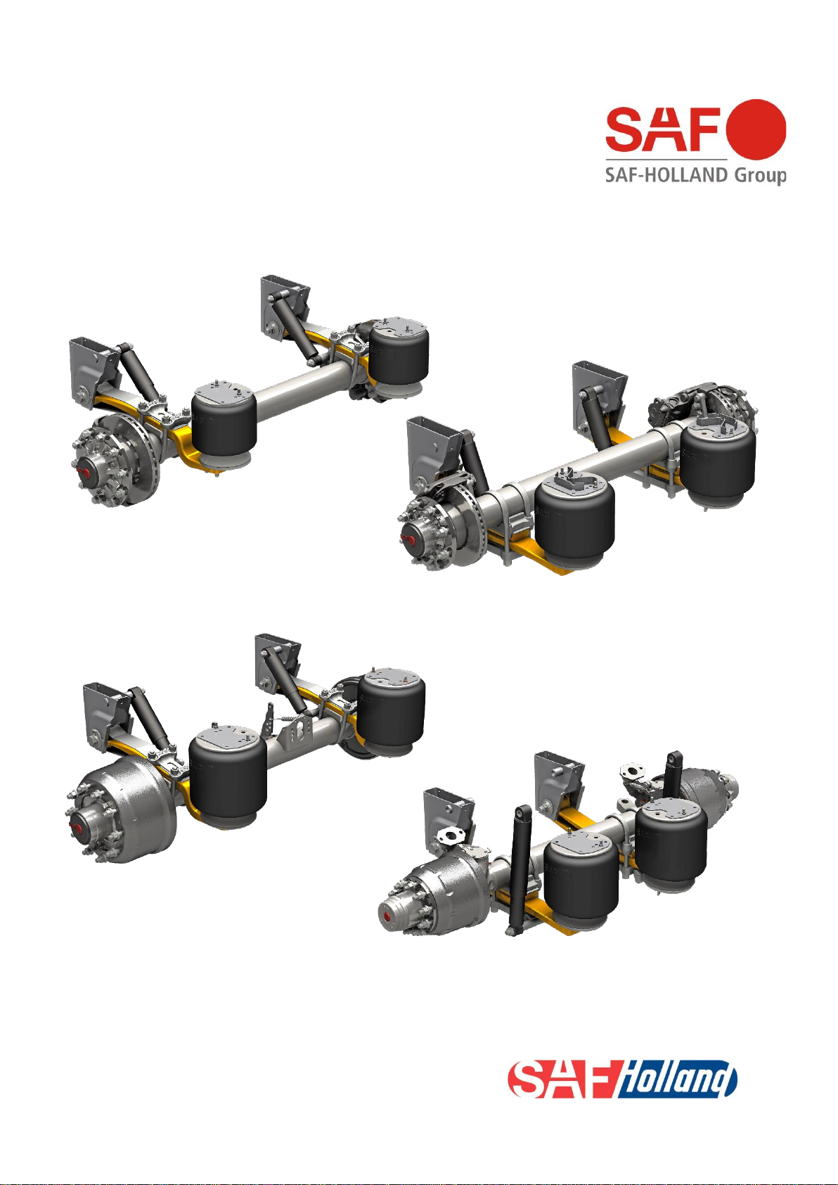
Design manual
SAF MODUL
disc brake
drum brake
Edition 2023-02
XL-AS10004DM-en-DE Rev C
Contents
Design manual modul, Edition 2023-02 Page 2 of 133
Amendments and errors excepted.
XL-AS10004DM
-en-DE Rev
C © SAF-HOLLAND
Realized updates of this version to Modul 2010-09
Page 7; Important Info 55, standardization of the serial number worldwide
As of page 17; General exposition
As of page 17; Important Info 72, introduction of single leaf trailing arm, 100x52 mm
As of page 23; Important Info 75, serial start of brake calliper SAF SBS1918
As of page 23; Important Info 100, serial start of brake calliper KNORR ST6
As of page 23; Important Info 102, optimized wheel end for axle model BI
As of page 29; Important Info 101, serial start of brake calliper SAF SBS2220 H01
As of page 29; Important Info 76, serial start of brake calliper SAF SBS2220 K0
As of page 33; Important Info 104, new axle versions 10 ton, 22,5” disc brake axles
As of page 36; Important Info 86, new axle versions 11 ton, 22,5” disc- and drum brake axles
As of page 38; Important Info 91, new axle versions 12 ton, 22,5” disc brake
As of page 56; Important Info 83, new axle version SKRZ12030S
As of page 64; Important Info 107, new axle versions 10 ton, 22,5” drum brake
As of page 70; Important Info 80, new axle version 12 ton, 22,5” drum brake
As of page 77; Important Info 110, new axle version low-loader, force-steered 17,5” and 19,5”, 11 ton
drum brake
As of page 112; Important Info 85, extended maintenance intervals for mounted components
As of page 115; Important Info 114, shape of the lever on slack adjusters
As of page 116; Important Info 99, updated test reports on brake chambers for disc brake
Contents
Design manual modul, Edition 2023-02 Page 3 of 133
Amendments and errors excepted.
XL-AS10004DM
-en-DE Rev
C © SAF-HOLLAND
Realized updates of this version to Modul 2010-09 ................................................................................ 2
Designation on type plate and serial number .......................................................................................... 7
Type identification for modul suspension ................................................................................................ 8
Type identification for axle generation SK ............................................................................................... 9
with drum brake ................................................................................................................................... 9
Type identification for axle generation 06 .............................................................................................. 10
with drum brake ................................................................................................................................. 10
with disc brake ................................................................................................................................... 10
Overview standard series at a glance ................................................................................................... 11
Overview special series at a glance ...................................................................................................... 12
Deployment recommendations and classification of component criteria .............................................. 13
Axle travel limitations at SAF air suspensions ....................................................................................... 14
Key ......................................................................................................................................................... 15
To choose a suspension assembly ....................................................................................................... 16
Calculation of suspension assembly weight .......................................................................................... 16
Air suspension serie U; .......................................................................................................................... 17
Single leaf trailing arm (EN) 52 mm with air bag 2618V (29) or 2923V (31) ..................................... 17
Air suspension serie MT; ....................................................................................................................... 18
Single leaf trailing arm (EN) 51 mm with air bag 2618V (29) or 2923V (31) ..................................... 18
Air suspension serie M; ......................................................................................................................... 19
Single leaf trailing arm (EN) 52 mm with air bag 2618V (29) or 2923V (31) ..................................... 19
Air suspension serie EO; ....................................................................................................................... 20
Single leaf trailing arm (EN) 52 mm with air bag 2618V (29) or 2923V (31) ..................................... 20
Air suspension serie U; .......................................................................................................................... 21
Double leaf trailing arm (S) 43/43 mm with air bag 2918V (27) or 2923V (31) ................................. 21
Air suspension serie M; ......................................................................................................................... 22
Double leaf trailing arm (S) 43/43 mm with air bag 2918V (27) or 2923V (31) ................................. 22
Axle version BI9-19…: ........................................................................................................................... 23
Axle version B9-19…: ............................................................................................................................ 24
Axle version SI9-19.: ............................................................................................................................. 25
Axle version ZI9-19.: .............................................................................................................................. 26
Axle version SI11-19K: .......................................................................................................................... 27
Axle version ZI11-19K: .......................................................................................................................... 28
Axle version BI9-22…: ........................................................................................................................... 29
Axle version B9-22…: ............................................................................................................................ 30
Axle version SI9-22…: ........................................................................................................................... 31
Axle version ZI9-22…: ........................................................................................................................... 32
Axle version BI10-22…: ......................................................................................................................... 33
Axle version SI10-22…: ......................................................................................................................... 34
Axle version ZI10-22…: ......................................................................................................................... 35
Axle version SI11-22K11: ...................................................................................................................... 36
Axle version SI12-22K10: ...................................................................................................................... 38
General information
Air suspension types for axles with disc brake
Rigid axles with disc brake
Contents
Design manual modul, Edition 2023-02 Page 4 of 133
Amendments and errors excepted.
XL-AS10004DM
-en-DE Rev
C © SAF-HOLLAND
Axle version BIL9-19.: ........................................................................................................................... 40
Axle version ZIL11-19K: ........................................................................................................................ 41
Axle version BIL9-22…: ......................................................................................................................... 42
Axle version SIL9-22…: ......................................................................................................................... 43
Axle version BIZL10-22…: ..................................................................................................................... 44
Axle version SIZL11-22K11: .................................................................................................................. 45
Axle version BIM9-..…: .......................................................................................................................... 46
Air suspension serie U; .......................................................................................................................... 47
Single leaf trailing arm (EN) 52 mm with air bag 2618V (29) or 2923V (31) ..................................... 47
Air suspension serie M; ......................................................................................................................... 48
Single leaf trailing arm (EN) 52 mm with air bag 2618V (29) or 2923V (31) ..................................... 48
Air suspension serie EO; ....................................................................................................................... 49
Single leaf trailing arm (EN) 52 mm with air bag 2618V (29) or 2923V (31) ..................................... 49
Air suspension serie U; .......................................................................................................................... 50
Double leaf trailing arm (S) 43/43 mm with air bag 2918V (27) or 2923V (31) ................................. 50
Air suspension serie M; ......................................................................................................................... 51
Double leaf trailing arm (S) 43/43 mm with air bag 2918V (27) or 2923V (31) ................................. 51
Axle version S7-3015: ........................................................................................................................... 52
Axle version Z7-3015: ............................................................................................................................ 53
Axle version Z9-3020: ............................................................................................................................ 54
Axle version Z11-3020: .......................................................................................................................... 55
Axle version SKRZ12030S: ................................................................................................................... 56
Axle version S9-3718: ........................................................................................................................... 57
Axle version Z9-3720: ............................................................................................................................ 58
Axle version S11-3720: ......................................................................................................................... 59
Axle version Z11-3720: .......................................................................................................................... 60
Axle version SKRZ12037: ..................................................................................................................... 61
Axle version S9-4218: ........................................................................................................................... 62
Axle version Z9-4218: ............................................................................................................................ 63
Axle version S10-4218: ......................................................................................................................... 64
Axle version Z10-4218: .......................................................................................................................... 65
Axle version S10-4220: ......................................................................................................................... 66
Axle version Z10-4220: .......................................................................................................................... 67
Axle version S11-4220S10: ................................................................................................................... 68
Axle version Z11-4220S10: ................................................................................................................... 69
Axle version S12-4220S10: ................................................................................................................... 70
Axle version Z12-4220S10: ................................................................................................................... 71
Self-steering axles with disc brake
Steered axles with disc brake
Hydraulic driven axle
Air suspension types for axles with drum brake
Axles with drum brake
Contents
Design manual modul, Edition 2023-02 Page 5 of 133
Amendments and errors excepted.
XL-AS10004DM
-en-DE Rev
C © SAF-HOLLAND
Axle version ZL11-3020: ........................................................................................................................ 72
Axle version SKRLZ12037: ................................................................................................................... 73
Axle version SL9-4218: ......................................................................................................................... 74
Axle version SL12-4220S10: ................................................................................................................. 75
Axle version SKZRLZ12030S: ............................................................................................................... 76
Axle version ZZL11-3720: ..................................................................................................................... 77
Axle version SZL11-4220S10: ............................................................................................................... 78
Geometry steel hanger bracket, shock absorber attachment over a fixed bolt ..................................... 79
Geometry steel hanger bracket, shock absorber attachment over a screw .......................................... 79
Geometry hanger bracket „screw-on“ .................................................................................................... 80
Geometry cross member, rigid axle ...................................................................................................... 82
Pivot bolt connection for steel hanger bracket and cross member ....................................................... 83
Shock absorber assembly: steel hanger bracket .................................................................................. 84
Geometry aluminium hanger bracket .................................................................................................... 85
Pivot bolt for aluminium hanger bracket ................................................................................................ 86
Shock absorber assembly: aluminium hanger bracket ......................................................................... 87
Shock absorber overview ...................................................................................................................... 88
Calculation of free space between tyre and air bag. ............................................................................. 89
Air bag overview .................................................................................................................................... 90
Calculation of the air bag pressure ........................................................................................................ 91
Force-pressure-diagram ........................................................................................................................ 92
Force-pressure diagram for air bag with diameter 300 mm .................................................................. 93
Force-pressure diagram for air bag with diameter 350 mm .................................................................. 94
Mounting plates for air bag offset (V) overview ..................................................................................... 95
Overview air bag brackets ..................................................................................................................... 96
Surface coating of SAF components ..................................................................................................... 97
Two side axle lift for axles with drum brake ........................................................................................... 98
Two side axle lift types ....................................................................................................................... 99
Kit content - two side axle lift ........................................................................................................... 100
Installation instruction ...................................................................................................................... 100
Circuit diagram, two side axle lift ..................................................................................................... 101
Pendulum lift ........................................................................................................................................ 102
Kit content pendulum lift ................................................................................................................... 103
Installation instruction ...................................................................................................................... 103
Centre axle lift ...................................................................................................................................... 104
For suspension series U with single- and double leaf trailing arm .................................................. 104
For suspension serie M with single- and double leaf trailing arm. ................................................... 105
Circuit diagram, one sided or pendulum lift ..................................................................................... 106
Self-steering axles with drum brake
Steered axles with drum brake
Assembly components
Axle lifts

Contents
Design manual modul, Edition 2023-02 Page 6 of 133
Amendments and errors excepted.
XL-AS10004DM
-en-DE Rev
C © SAF-HOLLAND
Welding instruction for steel hanger bracket ....................................................................................... 107
Welding instruction for aluminium hanger bracket .............................................................................. 108
Recommendation for lateral reinforcement of steel hanger bracket ................................................... 109
Welding instruction for air bag bracket ................................................................................................ 110
Installation of „screw-on“ hanger brackets .......................................................................................... 111
Tightening torques for trailing arm – shock absorber - air bag ............................................................ 112
Tightening instructions for adjustable pivot bolt .................................................................................. 113
Wheel fixing – Single 22,5“, drum brake (code 58) ............................................................................. 113
Brake chamber bracket ....................................................................................................................... 115
Overview SAF-HOLLAND brake chamber for axles with disc brake ................................................... 116
Type identification for SAF-HOLLAND brake chambers ................................................................. 117
Technical data .................................................................................................................................. 117
Installation instruction for brake chambers at axles with disc brake ................................................... 118
Self-steering axle with pneumatic steering stabilising ......................................................................... 119
Self-steering axle with stabilising damper ........................................................................................... 120
Caster ............................................................................................................................................... 121
Steering angle .................................................................................................................................. 121
Adjustment of the air suspension ride height ...................................................................................... 122
Ride heights ......................................................................................................................................... 123
Semi-trailer tilt angle ........................................................................................................................ 123
Axle alignment ..................................................................................................................................... 124
Classification of exciter ring teeth ........................................................................................................ 126
Installation instruction ABS cable ........................................................................................................ 127
Axle with disc brake ......................................................................................................................... 127
Axle with drum brake, rigid axles ..................................................................................................... 128
Connecting cable kit for pad wear sensing .......................................................................................... 129
SAF-O-Meter ....................................................................................................................................... 132
Recommendation for the technical requirement on the SAF TRAK .................................................... 133
This manual is over the internet available. The newest version is always to be found with:
http://designmanual.safholland.de.
Installation and welding instructions
Brake chamber
Self-steering axles
Axle, suspension settings
Miscellaneous

General information
Design manual modul, Edition 2023-02 Page 7 of 133
Amendments and errors excepted.
XL-AS10004DM
-en-DE Rev
C © SAF-HOLLAND
Designation on type plate and serial number
The data on the type plate is confirm the regulation for checking and homologating the brake systems
(by ECE R 13). The identification of the test equivalent and the applicability areas of the test report is
now described with the following four identifiers:
• ID 1 identifies the axle
• ID 2 identifies the brake
• ID 3 identifies the test axle load
• ID 4 identifies the test report number
The QR code
With a QR Code Reader and an internet access on a smart phone, tablet PC or with the (free of
charge) SAF-HOLLAND app, you can scan the data on the type plate. The QR Code will guide you to
the spare parts list of the scanned axle. The needed parts can than directly being ordered of the spare
parts list free of failure.
Example type plate
With Identifiers:
The serial number appears as follows:
XX JJ TTT NNNN
XX………………………………………. - code, Place of manufacture:
JJ ………………………………. - code, Year of manufacturing
TTT…………………… - code, Day of manufacturing
NNNN…. - code, Running number per day, year and place
Example serial number: 11 12 194 0155
This is about the 155th product of the 194th manufacturing day at the manufacturing year 2012 from
the manufacturing plant 11.
General information
Design manual modul, Edition 2023-02 Page 8 of 133
Amendments and errors excepted.
XL-AS10004DM
-en-DE Rev
C © SAF-HOLLAND
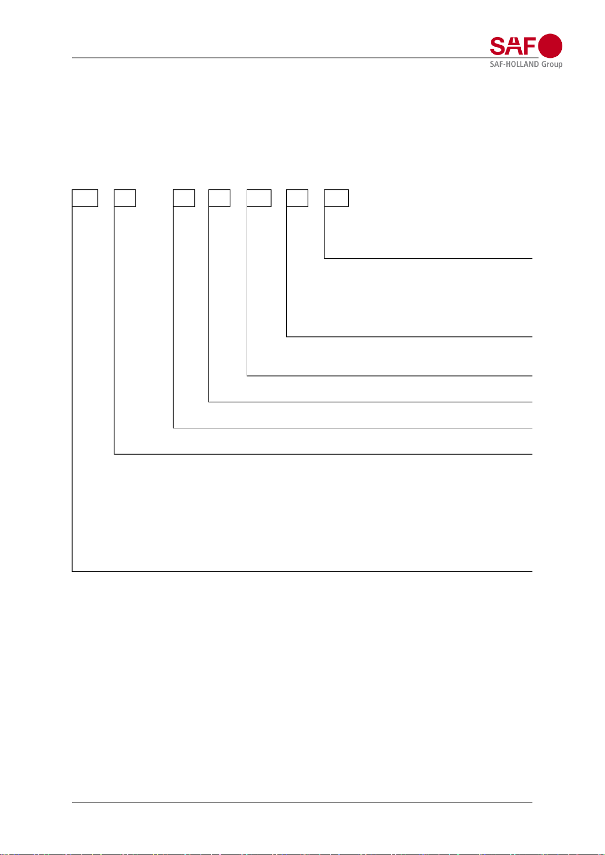
Type identification for modul suspension
Letters are marked with “X”, numbers with “0”
Example:
U 33 / 35 10 S 31 Q
EO 44 / 29 04 EN 27
XX 00 / 00 00 XX 00 XX
A = aluminium hanger bracket
B = hanger bracket "srew-on"
Q = Crossmember
Without specification = steel hanger bracket
27 = SAF 2918V - ø350 mm
42 = SAF 2919V - ø350 mm (observe applicability)
29 = SAF 2618V - ø300 mm
31 = SAF 2923V - ø350 mm
41 = SAF 2924V - ø350 mm (observe applicability)
EN = single leaf trailing arm 100 x52 mm
S = double leaf trailing arm 100 x 43/43 mm
air bag bracket height in cm
hanger bracket height in cm
ride height in cm
U = serie with trailing arm under the axle
MT = serie with a crancked trailing arm at the front and back of the axle
M = serie with a crancked trailing arm at the back of the axle
O = serie with trailing arm over the axle
EO = serie with a shortened triailing arm over the axle
HU = serie with a extented trailing arm under the axle
AR421 = serie with a extrem, extended trailing arm under the axle
AR421H = serie with a extrem, extended trailing arm under the axle and large axle travel
General information
Design manual modul, Edition 2023-02 Page 9 of 133
Amendments and errors excepted.
XL-AS10004DM
-en-DE Rev
C © SAF-HOLLAND
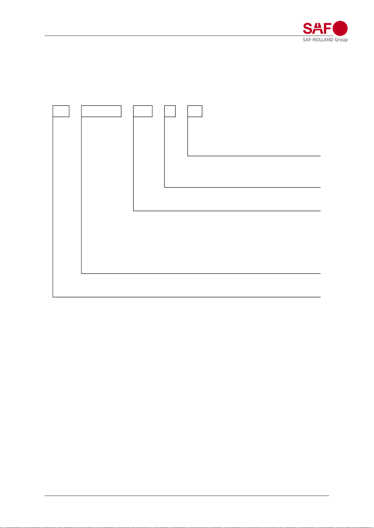
Type identification for axle generation SK
with drum brake
SK RLZ 12 0 37
SK (X)X(X)X (0)0 0 00
Brake dimension code:
42 = drum brake ø420 mm, 22,5" tyre size
37 = drum brake ø367 mm, 19,5" tyre size
30 = drum brake ø300 mm, 17,5" tyre size
Serie
0 = first serie
2 = second serie
Axle load
max. axle load [x 1.000 kg]
Version
RS = single tyre with offset 0 mm
RZ = twin tyre
RLS = self-steering axle, single tyre with offset 0 mm
RLZ = self-steering axle, twin tyre
ZRLS = steering axle, single tyre with offset 0 mm
ZRLZ = steering axle, twin tyre
Type
Super Compact
General information
Design manual modul, Edition 2023-02 Page 10 of 133
Amendments and errors excepted.
XL-AS10004DM
-en-DE Rev
C © SAF-HOLLAND
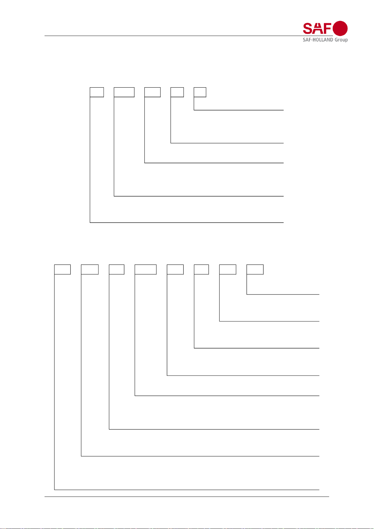
Type identification for axle generation 06
with drum brake
with disc brake
S 9 - 42 18
Z ZL 11 - 37 20
X (X)X (0)0 - 0 00
Brake width in cm
Brake dimension code
42 = drum brake ø420 mm, 22,5" tyre size
37 = drum brake ø367 mm, 19,5" tyre size
30 = drum brake ø300 mm, 17,5" tyre size
Axle load
max. axle load [x 1.000 kg]
Version
without = rigid axle
L = self-steering axle
ZL
= steering axle
Tyre type
S = single tyre with offset = 0 mm
Z = twin tyre
S I 12 - 22 K 1 0
B I L 9 - 19 S
X (X) (X) (0)0 - 00 X (0) (0)
Brake version
0 = running number
Hub unit version
0 or without = 88x120 bearing size
1 = 88x150 bearing size
Brake manufacturer
S = SAF
K = KNORR
Brake dimension code
19 = disc brake ø375 mm; 19,5"/22,5" tyre size
22 = disc brake ø430 mm; 22,5" tyre size
Axle load
max. axle load [x 1.000 kg]
Ausführung
without
= rigid axle
L = self-steering axle
ZL = steering axle
Type of disc
without = conventional disc brake
I = INTEGRAL-Technology
Tyre type
B = single tyre with offset = 120 mm
S = single tyre with offset = 0 mm
Z = twin tyre

General information
Design manual modul, Edition 2023-02 Page 11 of 133
Amendments and errors excepted.
XL-AS10004DM
-en-DE Rev
C © SAF-HOLLAND
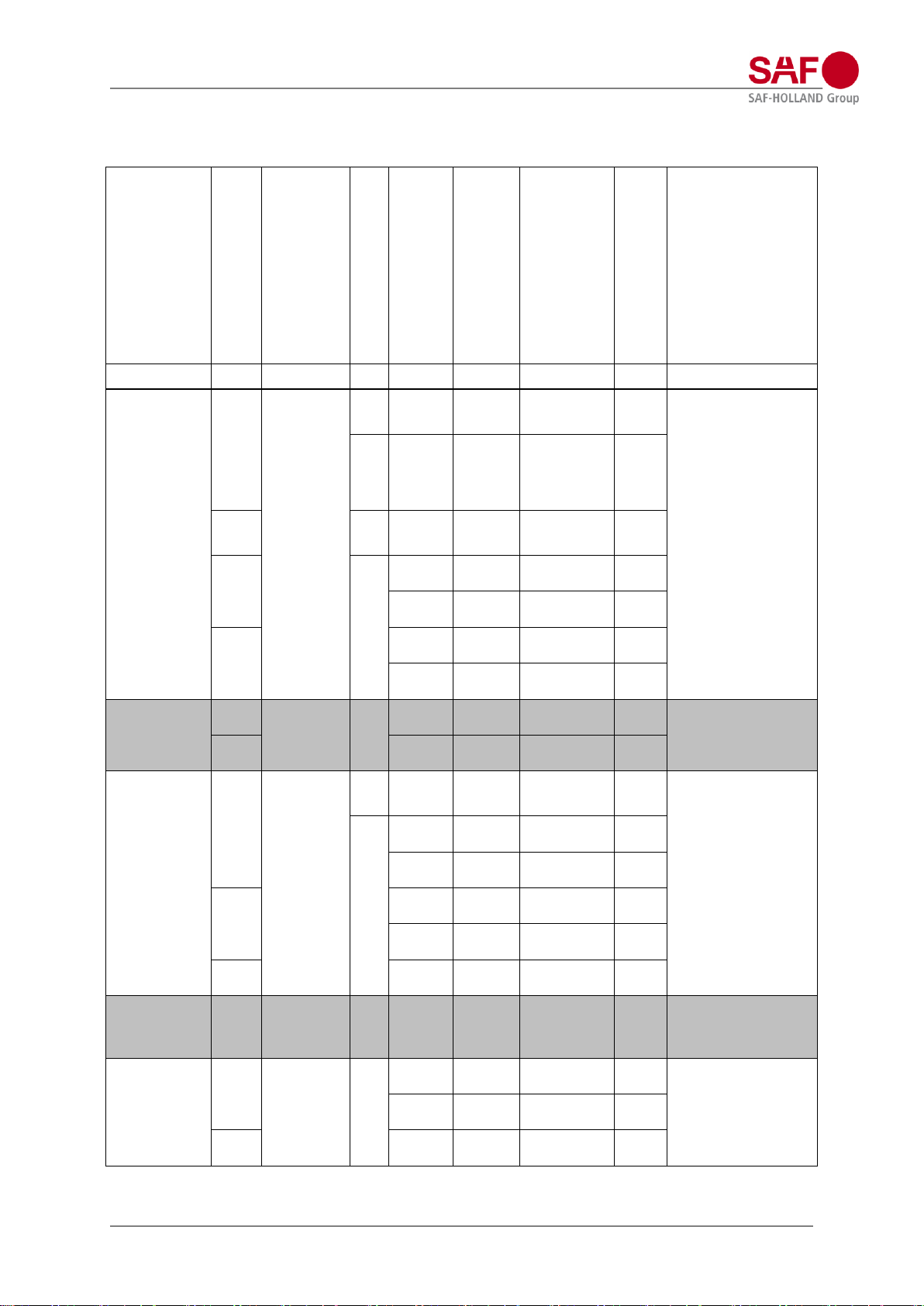
Overview standard series at a glance
Serie
Feature(s)
Trailing arm
variations
[mm]
F
[mm]
Total axle travel with air
bag:
[mm]
EN
(100 x 51
)
EN
(100 x 5
2)
S
(100 x 43/43
)
2618V
29
Ø300
2918V
27
Ø350
2923V
31
Ø350
2926V
30
Ø350
U
trailing arm
under the
axle
180
till
410
180
180
200
260
MT
crancked
trailing arm
over the
axle
250
till
410
180
180
200
260
M
crancked
trailing arm
over the
axle
340
till
535
180
180
200
260
O
trailing arm
over the
axle
400
till
600
180
180
200
260
EO
trailing arm
over the
axle, short
Laproportion
400
till
585
190
190
220

General information
Design manual modul, Edition 2023-02 Page 12 of 133
Amendments and errors excepted.
XL-AS10004DM
-en-DE Rev
C © SAF-HOLLAND
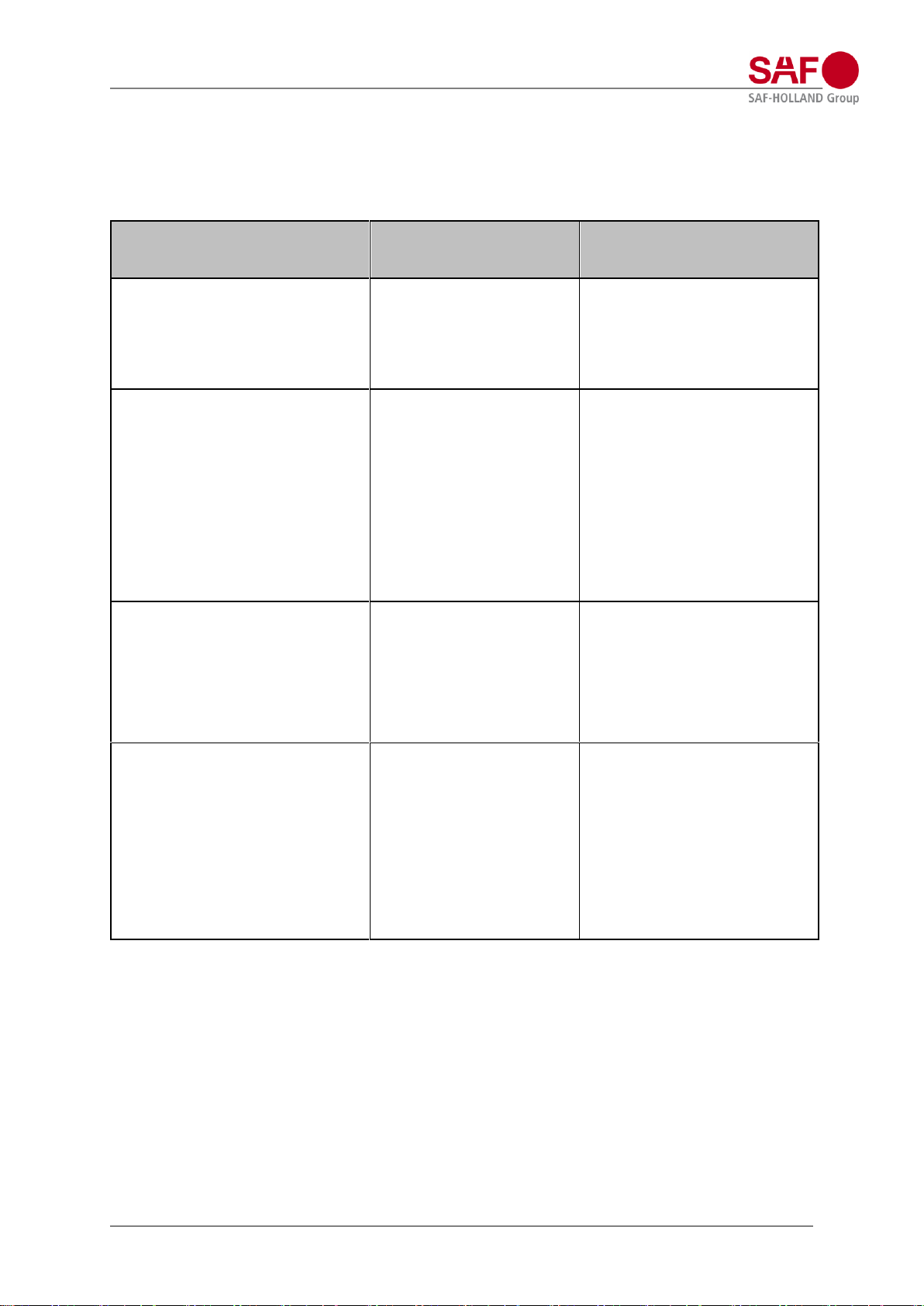
Overview special series at a glance
Serie
Feature(s)
Trailing arm
variations
[mm]
F
[mm]
Total axle travel with
air bag:
[mm]
E
(100 x 61
)
S
(100 x 54/54
)
2923V
31
Ø350
2926V
30
Ø350
3138
nv.
Ø390
HU
trailing arm
under the
axle,
extended
L1proportion
220
till
315
260
300
AR421
trailing arm
under the
axle,
extended
L1proportion
250
till
500
310
AR421H
trailing arm
under the
axle,
extended
L1proportion
380
till
480
420
at
9 t;
400
at
10 t
General information
Design manual modul, Edition 2023-02 Page 13 of 133
Amendments and errors excepted.
XL-AS10004DM
-en-DE Rev
C © SAF-HOLLAND
Deployment recommendations and classification of component criteria
Application
Axle load up to 105 km/h Axle beam Serie Trailing arm (width x thickness) Spring centre (◙ = no limitations) Spring seat Air bag
( Ø )
Notes
[t]
[mm]
[mm]
[mm]
standard
western
Europe
resp. onroad use
9
standard
MT
51 ◙ standard
300/
350
for container- and
coil-trailers: quick
release valve or
arresting cable
U/M/EO
52 ◙ standard
300/
350
10
MT
51
> 1050
heavy duty
350
11
U/M/EO
52
> 1050
standard
350
52
≤ 1050
heavy duty
350
12
52
> 1050
heavy duty
350
43/43
◙
heavy duty
350
mega-trailer
10
standard
HU
60 ◙ standard
350
long stroke
11
54/54
◙
heavy duty
350
eastern
Europe or
comparable
conditions
9
reinforced
MT
51
> 1050
standard
350
for container- and
coil-trailers: quick
release valve or
arresting cable
U/M/EO
52
> 1050
standard
350
52
≤1050
heavy duty
350
11
52
> 1050
heavy duty
350
43/43
◙
heavy duty
350
12
43/43
◙
heavy duty
350
tipper
western
Europe
9
reinforced
M/EO
52 ◙ standard
350
quick release valve
or arresting cable
tipper heavy
use/ logging
9
reinforced
M/EO
52
> 1050
standard
350
quick release valve
or arresting cable
52
≤ 1050
heavy duty
350
12
43/43
◙
heavy duty
350
General information
Design manual modul, Edition 2023-02 Page 14 of 133
Amendments and errors excepted.
XL-AS10004DM
-en-DE Rev
C © SAF-HOLLAND
Axle travel limitations at SAF air suspensions
Basically it is in the design of SAF air suspension that there is no need for axle travel limitations.
However there are some to operational conditions required exceptions:
Operating condition
Sling
Height limiting valve
Raise- and lowering device (e.g.
adapting trailer to bank heights/
demountable body systems
REQUIRED
(alternative height
limiting valve)
NOT REQUIRED
when raise/ lower valve with
DEADMAN HANDLE is fitted
Roll on/ Roll off applications
with air pressure in the air
bags
REQUIRED
without air pressure in the air
bags (wit SAF standard air
bags and use of anti-vacuumvalve)
REQUIRED
(rubber part of the air
bag has to stay rolled
on over the piston at
maximum axle travel)
Quick discharging
for example coil-trailers
with raise and lowering device
(discharging in „raised“
position)
REQUIRED
Ferry operation
with air pressure in the air
bags
REQUIRED
without air pressure in the air
bags (wit SAF standard air
bags and use of anti-vacuumvalve)
REQUIRED
(rubber part of the air
bag has to stay rolled
on over the piston at
maximum axle travel)

General information
Design manual modul, Edition 2023-02 Page 15 of 133
Amendments and errors excepted.
XL-AS10004DM
-en-DE Rev
C © SAF-HOLLAND
Key
Summary Explanation
A Unsprung mass
AX Distance wheel attachment faces left to right
B Total width
BH Hanger bracket height, distance centre pivot bolt to top side hanger bracket
BL Hanger bracket length, distance top hanger bracket from front- to backside
BM Air bag centre, distance air bag centre line between left- and right side
ET Offset, distance wheel attachment face to centre tyre
DP Pivot point centre (steering axle), distance pivot bolts centre line between left- and right
side
F Nominal ride height, distance centre axle to bottom chassis in driving condition
G Total axle width
H Air bag bracket height
H2 Air bag bracket height at lift air bag
HM Hanger bracket centre, distance hanger bracket centre line between left- and right side
Hmax Air bag height maximum
Hmin Air bag height minimum
i Ratio
K Brake chamber centre (with drum brake), centre distance brake chamber bracket
between left- and right side
KTL Cathodic dip coating
L Trailing arm length (L1), distance centre pivot bolt to centre axle (standard 500 mm)
La Distance centre axle to centre air bag (L2, standard 385 mm)
LM Spring centre, centre distance spring between left- and right side
Lmax Shock absorber length maximum
Lmin Shock absorber length minimum
P Air pressure in the air bag (Mpa)
p Air pressure in the air bag (Mpa/kg)
Pt Air pressure in the air bag at partial load (Mpa)
Q Axle load on the ground (kg)
Qt Axle load on the ground at partial load (kg)
S Track, centre distance tyres between left- and right side
V Air bag offset, distance centre air bag to centre spring
X Overall height, distance centre axle to under side of chassis beam when air bags are
without air
Y Installation height of liftarm, when raised.
All measurements are given in mm if not specified otherwise.
General information
Design manual modul, Edition 2023-02 Page 16 of 133
Amendments and errors excepted.
XL-AS10004DM
-en-DE Rev
C © SAF-HOLLAND
To choose a suspension assembly
For example an assembly with the following data:
Air suspension: Overall height (X), unladen without air: 280 mm
lowering travel: 90 mm
adjusted ride height (F): 370 mm
standard air bag Ø 300 mm
spring centre: 1300 mm
Axle: axle with disc brake 22,5“, axle load maximum 9.000 kg
tyre size: 385/65R22,5“ on a wheel with offset 0 mm
total width (distance outside tyres left to right) maximum: 2490 mm
With this data:
Suspension as on page 19, air suspension for axles with disc brake.
Air suspension type: M36/2500EN29.
Axle as on page 31, axle with disc brake 22,5“. Axle version: SI9-22S
Tyre 385/65R22,5“ has a width of 405 mm (E.T.R.T.O. Norm).
With a maximum total width of 2490 mm you can calculate the maximum distance wheel attachment
faces (2490 – 405 + 2 x 0 =) 2085 mm.
For this, the suspension assembly is described as:
M36/2500EN29 SI9-22S
Distance wheel attachment faces: 2040 mm
Spring centre: 1300 mm
With an air bag offset of 30 mm, you’ll get a free space between tyre and air bag of:
Calculation:
see also page 89
Calculation of suspension assembly weight
The total weight of this assembly is the sum of the weights of air suspension type and axle.
M36/2500EN29 weight air suspension type (page 19) 176 kg
SI9-22S, distance wheel attachment faces 2040 mm weight axle (page 31) 292 kg
total weight suspension assembly: 468 kg
Weights are without slack adjusters (axles with drum brake), brake chambers and wheel nuts. Weight
deviations lie within the permitted DIN tolerances for the respective manufacturing process.
mm255,470- 30
2
40530013002040
=+
−−−
Air suspension types for axles with disc brake
Design manual modul, Edition 2023-02 Page 17 of 133
Amendments and errors excepted.
XL-AS10004DM
-en-DE Rev
C © SAF-HOLLAND
Air suspension serie U;
Single leaf trailing arm (EN) 52 mm with air bag 2618V (29) or 2923V (31)
Nominal ride heights 240 – 365 mm
U../….EN29
U../….EN31
ride height
range
[mm]
X; overall height
1)
weight
approx.2)
[kg]
air suspension type
F; nominal
ride height
[mm]
unladen
without air
[mm]
laden
without air
[mm]
U24/2904EN29 3)
240
220-260
150
135
189
U25/2907EN29 3)
255
235-275
165
150
190
U27/2910EN29
270
250-290
180
165
191
U30/3510EN29 3)
300
280-320
210
195
196
U31/3513EN29 3)
315
295-335
225
210
197
U33/3516EN29
335
315-355
245
230
198
U27/2904EN31 3)
270
240-300
170
155
204
U28/2907EN31
290
260-320
190
175
205
U30/2910EN31
305
275-335
205
190
206
U33/3510EN31
335
305-365
235
220
211
U35/3513EN31
350
320-380
250
235
212
U36/3516EN31
365
335-395
265
250
213
1) The data in the table corresponds with an air bag offset (V) of 0 or 30 mm, with V = 55 mm or V = 70 mm the
overall height X is increased by 5 mm (so changes the ride height range accordantly)
2) Weight deviations lie within the permitted DIN Tolerances for the respective manufacturing process.
3) Only possible in combination for axle versions with 19,5” disc brake
Use of cross member and aluminium hanger bracket is not applicable.
Further variants on request
front
total axle travel
total axle travel
Air suspension types for axles with disc brake
Design manual modul, Edition 2023-02 Page 18 of 133
Amendments and errors excepted.
XL-AS10004DM
-en-DE Rev
C © SAF-HOLLAND
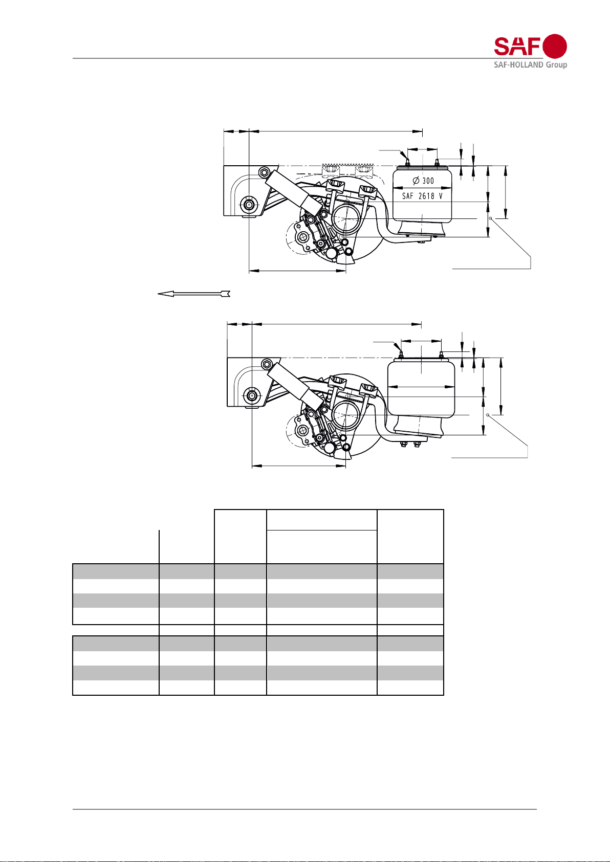
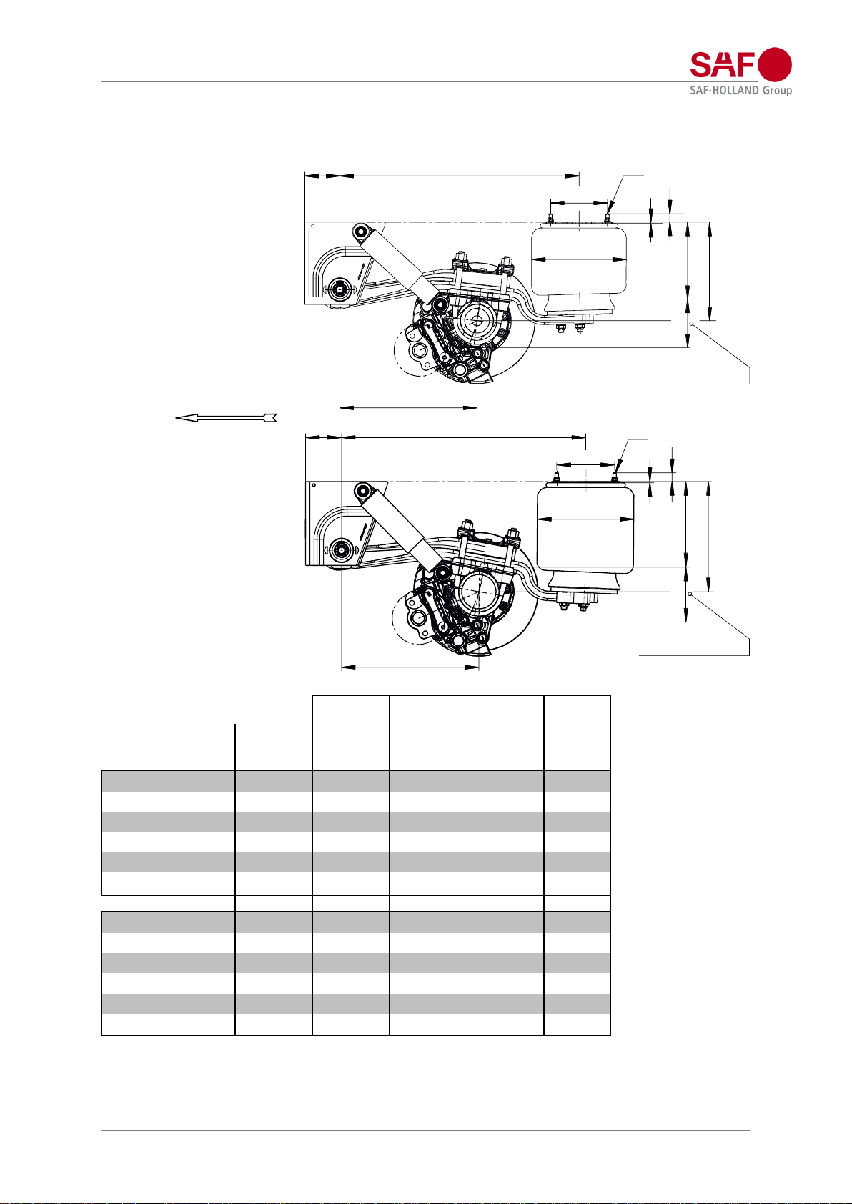
Air suspension serie MT;
Single leaf trailing arm (EN) 51 mm with air bag 2618V (29) or 2923V (31)
Nominal ride heights 270 – 380 mm
MT../….EN29
MT../….EN31
X; overall height
1)
air suspension type
F; nominal
ride height
[mm]
ride height
range
[mm]
unladen
without air
[mm]
laden
without air
[mm]
weight
approx.2)
[kg]
MT27/2000EN29 3)
270
250-290
180
180
177
MT30/2005EN29
300
280-320
210
195
182
MT32/2505EN29
320
300-340
230
215
185
MT35/2510EN29
350
330-370
260
245
187
MT30/2000EN31
305
275-335
205
190
190
MT33/2005EN31
330
300-360
230
215
195
MT35/2505EN31
355
325-385
255
240
198
MT38/2510EN31
380
350-410
280
265
200
1) The data in the table corresponds with an air bag offset (V) of 0 or 30 mm, with V = 55 mm or V = 70 mm the
overall height X is increased by 5 mm (so changes the ride height range accordantly)
2) Weight deviations lie within the permitted DIN Tolerances for the respective manufacturing process.
3) Air suspension types MT27/2000EN29, contact at the axle clamping to chassis beam in position without air
(unladen without air = laden without air)
Use of aluminium hanger bracket is not applicable.
Further variants on request.
150
( 500 )
130
31
M12
885
X
180
F
5
210
( 500 )
130
M12
Ø 350
SAF 2923 V
885
X
200
F
31
5
front
total axle travel
total axle travel
Air suspension types for axles with disc brake
Design manual modul, Edition 2023-02 Page 19 of 133
Amendments and errors excepted.
XL-AS10004DM
-en-DE Rev
C © SAF-HOLLAND
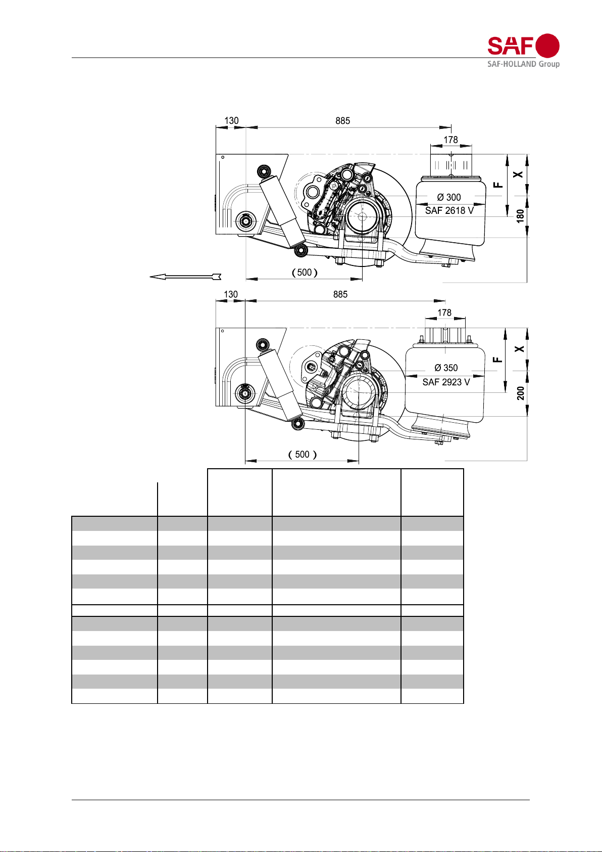
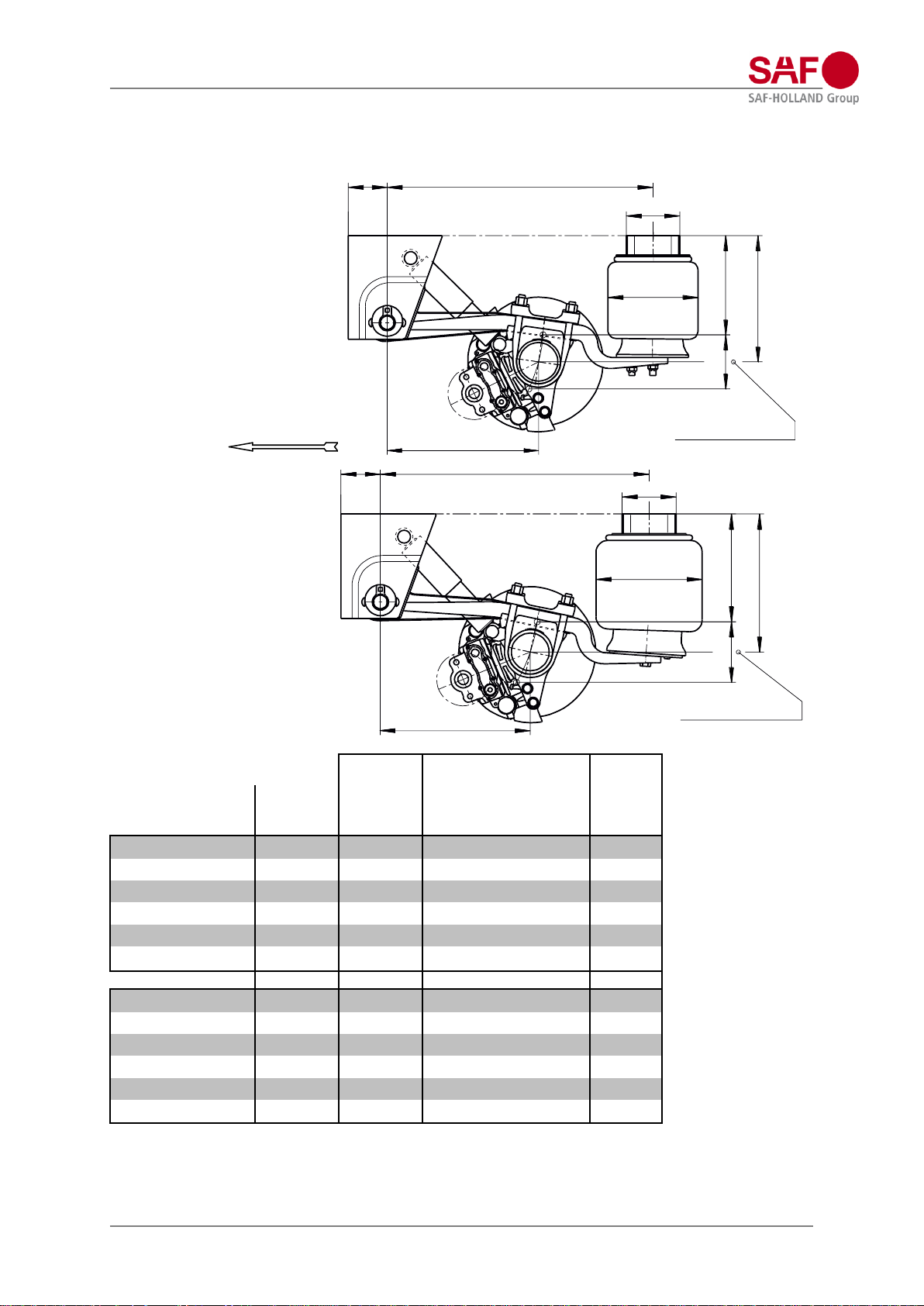
Air suspension serie M;
Single leaf trailing arm (EN) 52 mm with air bag 2618V (29) or 2923V (31)
Nominal ride heights 370 – 505 mm
M../….EN29
M../….EN31
X; overall height
1)
air suspension type
F; nominal
ride height
[mm]
ride height
range
[mm]
unladen
without air
[mm]
laden
without air
[mm]
weight
approx. 2)
[kg]
M36/2500EN29
370
350-390
280
265
176
M38/2504EN29
390
370-410
300
285
177
M40/2904EN29
410
390-430
320
305
180
M42/2907EN29
425
405-445
335
320
181
M43/2910EN29
445
425-465
355
340
182
M46/3510EN29
470
450-490
380
365
187
M40/2500EN31
405
375-435
305
290
191
M42/2504EN31
425
395-455
325
310
192
M43/2904EN31
445
415-475
345
330
195
M45/2907EN31
460
430-490
360
345
196
M47/2910EN31
480
450-510
380
365
197
M50/3510EN31
505
475-535
405
390
202
1) The data in the table corresponds with an air bag offset (V) of 0 or 30 mm, with V = 55 mm or V = 70 mm the
overall height X is increased by 5 mm (so changes the ride height range accordantly)
2) Weight deviations lie within the permitted DIN Tolerances for the respective manufacturing process.
Further variants on request.
178
885130
( 500 )
X
180
F
SAF 2618 V
Ø 300
130 885
178
Ø 350
( 500 )
SAF 2923 V
X
200
F
front
total axle travel
total axle travel
Air suspension types for axles with disc brake
Design manual modul, Edition 2023-02 Page 20 of 133
Amendments and errors excepted.
XL-AS10004DM
-en-DE Rev
C © SAF-HOLLAND
Air suspension serie EO;
Single leaf trailing arm (EN) 52 mm with air bag 2618V (29) or 2923V (31)
Nominal ride heights 420 – 555 mm
EO../….EN29
EO../….EN31
X; overall height
1)
air suspension type
F; nominal
ride height
[mm]
ride height
range
[mm]
unladen
without air
[mm]
laden
without air
[mm]
weight
approx. 2)
[kg]
EO41/2500EN29
420
400-440
330
315
173
EO42/2900EN29
435
415-455
345
330
176
EO44/2904EN29
455
435-475
365
350
177
EO47/3504EN29
480
460-500
390
375
182
EO49/3507EN29
500
480-520
410
395
183
EO50/3510EN29
520
500-540
430
415
184
EO44/2500EN31
455
425-485
355
340
188
EO46/2900EN31
470
440-500
370
355
191
EO48/2904EN31
495
465-525
395
380
192
EO50/3504EN31
515
485-545
415
400
197
EO52/3507EN31
535
505-565
435
420
198
EO54/3510EN31
555
525-585
455
440
199
1) The data in the table corresponds with an air bag offset (V) of 0, 30, 55 or 70 mm.
2) Weight deviations lie within the permitted DIN Tolerances for the respective manufacturing process.
Further variants on request.
X
180
F
840
130
( 500 )
SAF 2618 V
Ø 300
150
31
5
M12
X
200
F
840
130
( 500 )
150
31
5
M12
SAF 2923 V
Ø 350
front
total axle travel
total axle travel
Air suspension types for axles with disc brake
Design manual modul, Edition 2023-02 Page 21 of 133
Amendments and errors excepted.
XL-AS10004DM
-en-DE Rev
C © SAF-HOLLAND
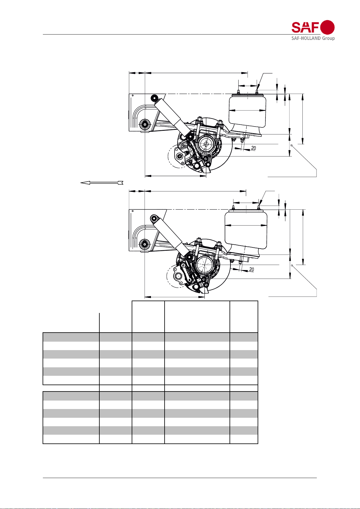
Air suspension serie U;
Double leaf trailing arm (S) 43/43 mm with air bag 2918V (27) or 2923V (31)
Nominal ride heights 240 – 370 mm
U../….S27
U../….S31
ride height
range
[mm]
X; overall height
1)
weight
approx.2)
[kg]
air suspension type
F; nominal
ride height
[mm]
unladen
without air
[mm]
laden
without air
[mm]
U24/2904S27 3)
240
220-260
150
140
219
U25/2907S27 3)
255
235-275
165
155
220
U27/2910S27
270
250-290
180
170
221
U30/3510S27 3)
300
280-320
210
200
226
U31/3513S27 3)
315
300-340
230
220
227
U33/3516S27
330
315-355
245
235
228
U27/2904S31 3)
270
245-305
175
165
221
U28/2907S31
285
260-320
190
180
222
U30/2910S31
300
275-335
205
195
223
U33/3510S31
330
305-365
235
225
228
U35/3513S31
350
320-380
250
240
229
U36/3516S31
370
340-400
270
260
230
1) The data in the table corresponds with an air bag offset (V) of 0 or 30 mm, with V = 55 mm or V = 70 mm the
overall height X is increased by 5 mm (so changes the ride height range accordantly)
2) Weight deviations lie within the permitted DIN Tolerances for the respective manufacturing process.
3) Only possible in combination for axle versions with 19,5” disc brake
Use of cross member and hanger bracket „aluminium“ is not applicable.
Further variants on request.
X
180
F
885
(500)
130
178
Ø 350
SAF 2918 V
130 885
178
Ø 350
(500)
SAF 2923 V
X
200
F
front
total axle travel
total axle travel
Air suspension types for axles with disc brake
Design manual modul, Edition 2023-02 Page 22 of 133
Amendments and errors excepted.
XL-AS10004DM
-en-DE Rev
C © SAF-HOLLAND
Air suspension serie M;
Double leaf trailing arm (S) 43/43 mm with air bag 2918V (27) or 2923V (31)
Nominal ride heights 370 – 505 mm
M../….S27
M../….S31
X; overall height
1)
air suspension type
F; nominal
ride height
[mm]
ride height
range
[mm]
unladen
without air
[mm]
laden
without air
[mm]
weight
approx.2)
[kg]
M36/2500S27
370
350-390
280
270
209
M38/2504S27
390
370-410
300
290
210
M40/2904S27
410
390-430
320
310
213
M42/2907S27
425
405-445
335
325
214
M43/2910S27
445
425-465
355
345
215
M46/3510S27
470
450-490
380
370
220
M40/2500S31
405
375-435
305
295
211
M42/2504S31
425
395-455
325
315
212
M43/2904S31
440
410-470
340
330
215
M45/2907S31
460
430-490
360
350
216
M47/2910S31
475
445-505
375
365
217
M50/3510S31
505
475-535
405
395
222
1) The data in the table corresponds with an air bag offset (V) of 0 or 30 mm, with V = 55 mm or V = 70 mm the
overall height X is increased by 5 mm (so changes the ride height range accordantly)
2) Weight deviations lie within the permitted DIN Tolerances for the respective manufacturing process.
Further variants on request.
130
885
5
(500)
F
X
180
210
M12
31
Ø 350
SAF 2918 V
130
885
5
Ø 350
(500)
SAF 2923 V
F
X
200
210
M12
31
total axle travel
Front
total axle travel
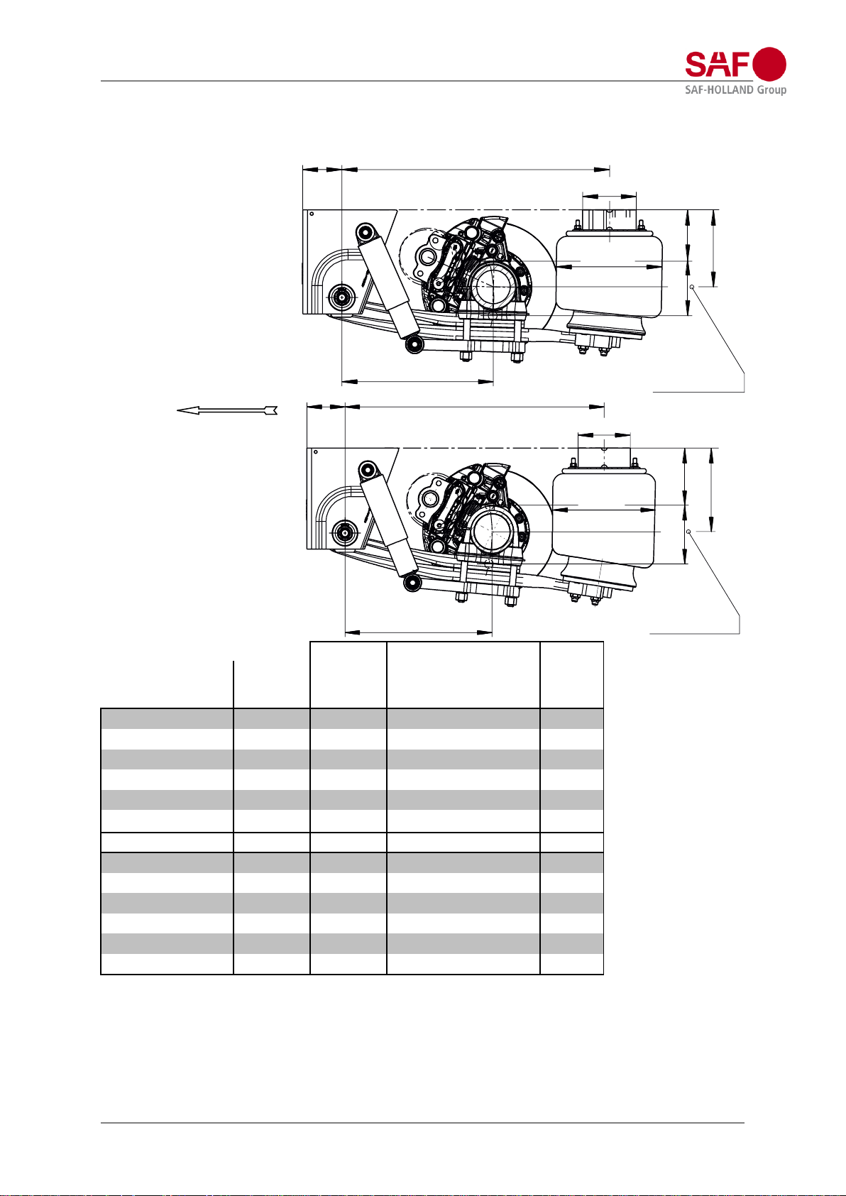
Rigid axle with disc brake
Design manual modul, Edition 2023-02 Page 23 of 133
Amendments and errors excepted.
XL-AS10004DM
-en-DE Rev
C © SAF-HOLLAND
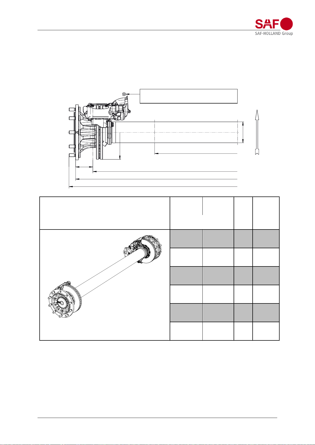
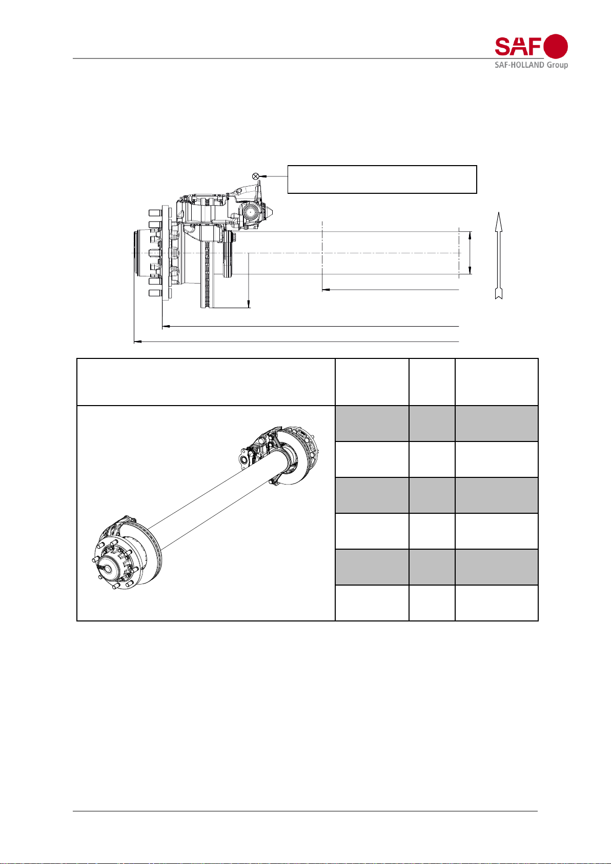
Axle version BI9-19…:
Axle load maximum: 9.000 kg
Axle beam Ø 146 mm
Wheel fixing: 10 / 280 / 335 / 22x1,5 mm
Suitable for: Air suspension series U, MT, M, EO with single leaf trailing arm (EN) and
Air suspension series U, M with double leaf trailing arm (S)
Air bags with air bag diameter Ø 300 mm and Ø 350 mm
axle version/ axle / brake/ test report
AX / LM
[mm]
S 1) / LM
[mm]
G 2)
[mm]
weight
approx.3)
[kg]
tyre (example):
425/55R19,5“
BI9-19S / SBS1937 / SAF, SBS1918 / TDB0870
BI9-19K / SBK1937- / KNORR, SBK1937 / TDB0605
2210/1100
1970/1100
2302
276
2210/1200 4)
1970/1200 4)
2302
276
2250/1200
2010/1200
2342
277
2280/1200
2040/1200
2372
278
2280/1300 4)
2040/1300 4)
2372
278
2330/1300
2090/1300
2422
280
1) S = AX – 2 x ET (120 mm)
2) G is increased by 20 mm when wheel studs are used for mounting aluminium rims.
3) Axle version with SAF-HOLLAND brake calliper (SBS1918); with KNORR brake calliper (SBK1937) an
additional weight of 5 kg per axle needs to be accounted for.
Without spring seats, brake chambers and wheel nuts (spring seats are enclosed in the air suspension).
Weight deviations lie within the permitted DIN Tolerances for the respective manufacturing process.
4) with tyres 425/55R19,5“ and air bag diameter Ø 300 mm starting at V = 30 mm
Note:
When choosing the suspension assembly, the clearance between air bag (max. diameter) and chosen tyre must
be checked, this should be at least 25 mm.
Further variants on request.
ET 120
Ø 146
Ø 377
LM – spring centre
Respect the calliper displacement of 30 mm for
adjacent parts due to the pad and disc wear
S – track
AX – distance wheel attachment faces
G – total axle width
Front

Rigid axle with disc brake
Design manual modul, Edition 2023-02 Page 24 of 133
Amendments and errors excepted.
XL-AS10004DM
-en-DE Rev
C © SAF-HOLLAND
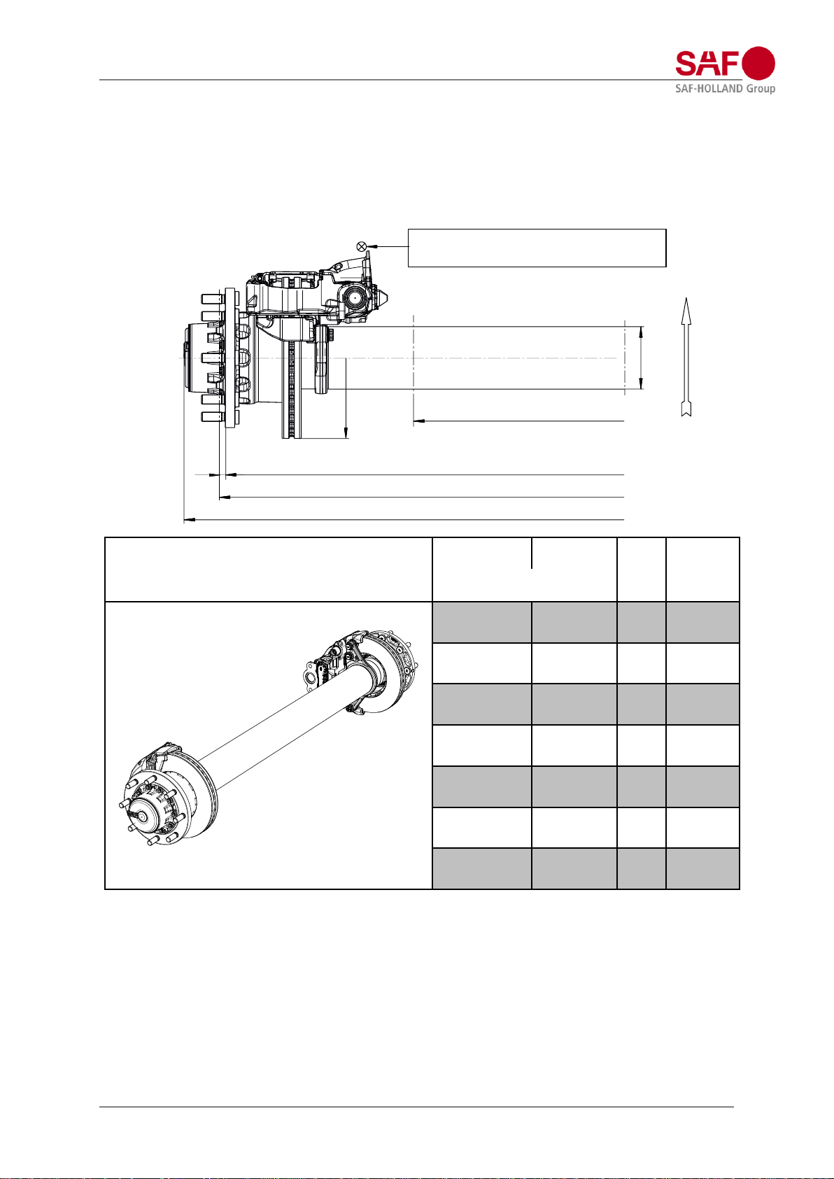
Axle version B9-19…:
Axle load maximum: 9.000 kg
Axle beam Ø 146 mm
Wheel fixing: 10 / 280 / 335 / 22x1,5 mm
Suitable for: Air suspension series U, MT, M, EO with single leaf trailing arm (EN) and
Air suspension series U, M with double leaf trailing arm (S)
Air bags with air bag diameter Ø 300 mm and Ø 350 mm
axle version / axle type / brake / test report
AX / LM
[mm]
S 1) / LM
[mm]
G 2)
[mm]
weight
approx.3)
[kg]
tyre (example):
425/55R19,5“
B9-19S / SBS1937 / SAF, SBS1918 / TDB0870
B9-19K / SBK1937- / KNORR, SBK1937 / TDB0605
2210/1100
1970/1100
2302
282
2210/1200 4)
1970/1200 4)
2302
282
2250/1200
2010/1200
2342
283
2280/1200
2040/1200
2372
284
2280/1300 4)
2040/1300 4)
2372
284
2330/1300
2090/1300
2422
286
1) S = AX – 2 x ET (120 mm)
2) G is increased by 20 mm when wheel studs are used for mounting aluminium rims.
3) Axle version with SAF-HOLLAND brake calliper (SBS1918); with KNORR brake calliper (SBK1937) an
additional weight of 5 kg per axle needs to be accounted for.
Without spring seats, brake chambers and wheel nuts (spring seats are enclosed in the air suspension).
Weight deviations lie within the permitted DIN Tolerances for the respective manufacturing process.
4) with tyres 425/55R19,5“ and air bag diameter Ø 300 mm starting at V = 30 mm
Note:
When choosing the suspension assembly, the clearance between air bag (max. diameter) and chosen tyre must
be checked, this should be at least 25 mm.
Further variants on request.
ET 120
Ø 146
Ø 377
LM – spring centre
Respect the calliper displacement of 30 mm for
adjacent parts due to the pad and disc wear
AX – distance wheel attachment faces
G – total axle width
Front
S – track
Rigid axle with disc brake
Design manual modul, Edition 2023-02 Page 25 of 133
Amendments and errors excepted.
XL-AS10004DM
-en-DE Rev
C © SAF-HOLLAND
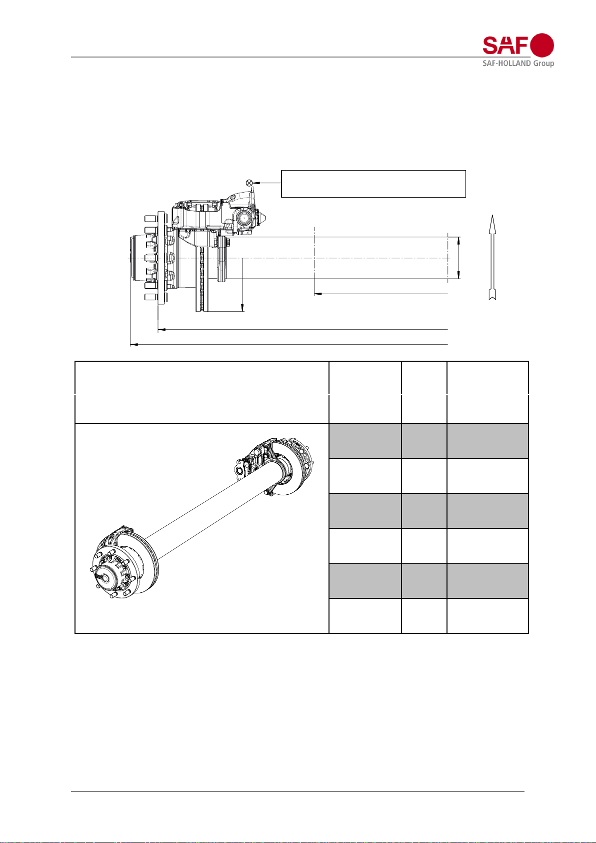
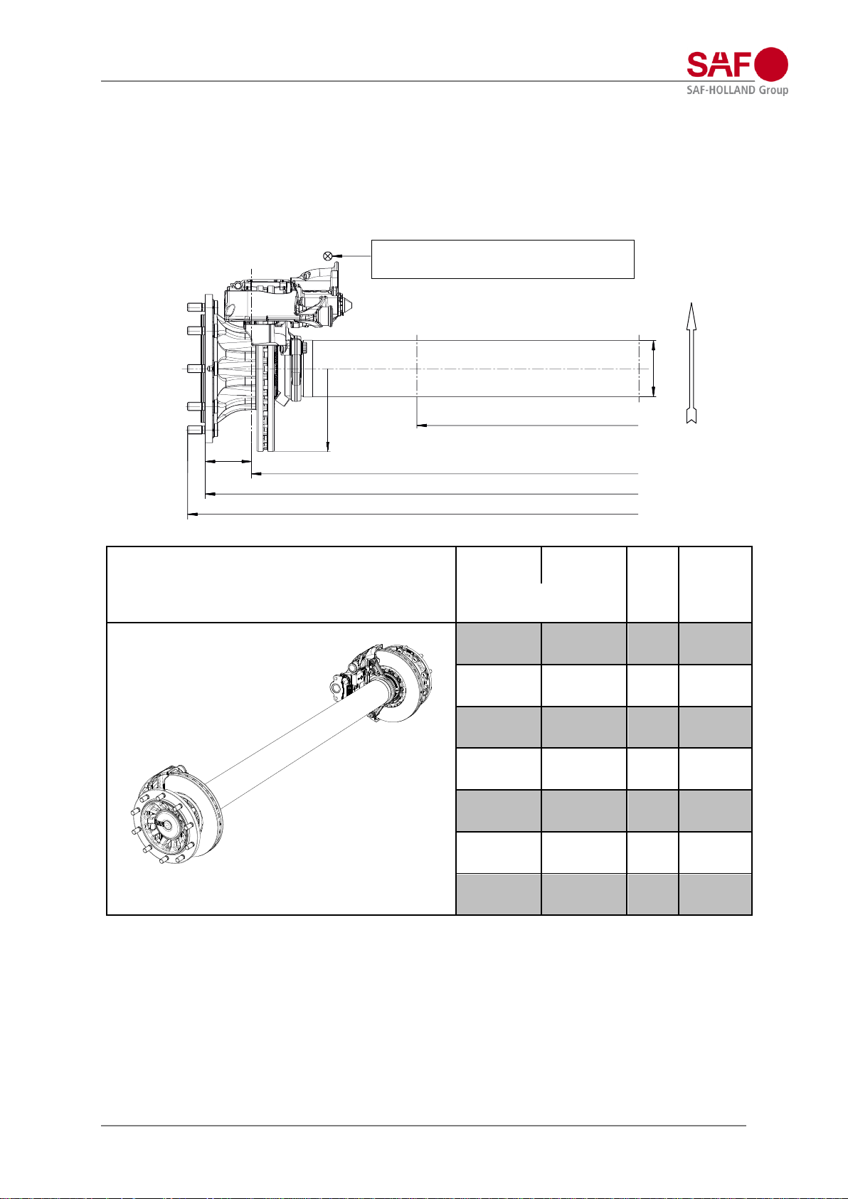
Axle version SI9-19.:
Axle load maximum: 9.000 kg
Axle beam Ø 146 mm
Wheel fixing: 8 / 220 / 275 / 22x1,5 mm
Suitable for: Air suspension series U, MT, M, EO with single leaf trailing arm (EN) and
Air suspension series U, M with double leaf trailing arm (S)
Air bags with air bag diameter Ø 300 mm and Ø 350 mm
axle version / axle type / brake / test report
AX 1) / LM
[mm]
G
[mm]
weight
approx.2)
[kg]
tyre (example):
425/55R19,5“
SI9-19S / SBS1937 / SAF, SBS1918 / TDB0870
SI9-19K / SBK1937 / KNORR, SBK1937 / TDB0605
1970/1100
2168
271
1970/1200
3,4)
2168
271
2010/1180
2208
272
2040/1200
2238
273
2040/1300
3,4)
2238
273
2090/1300 4)
2288
275
1) AX = S
2) Axle version with SAF-HOLLAND brake calliper (SBS1918); with KNORR brake calliper (SBK1937) an
additional weight of 5 kg per axle needs to be accounted for.
Without spring seats, brake chambers and wheel nuts (spring seats are enclosed in the air suspension).
Weight deviations lie within the permitted DIN Tolerances for the respective manufacturing process.
3) with tyres 425/55R19,5“ and air bag diameter Ø 300 mm starting at V = 30 mm
4) to be combined with air suspension types starting at a nominal ride height of 330 mm.
Note:
When choosing the suspension assembly, the clearance between air bag (max. diameter) and chosen tyre must
be checked, this should be at least 25 mm.
Further variants on request.
Ø 146
Ø 377
LM – spring centre
Respect the calliper displacement of 30 mm for
adjacent parts due to the pad and disc wear
AX – distance wheel attachment faces
G – total axle width
Front
Rigid axle with disc brake
Design manual modul, Edition 2023-02 Page 26 of 133
Amendments and errors excepted.
XL-AS10004DM
-en-DE Rev
C © SAF-HOLLAND
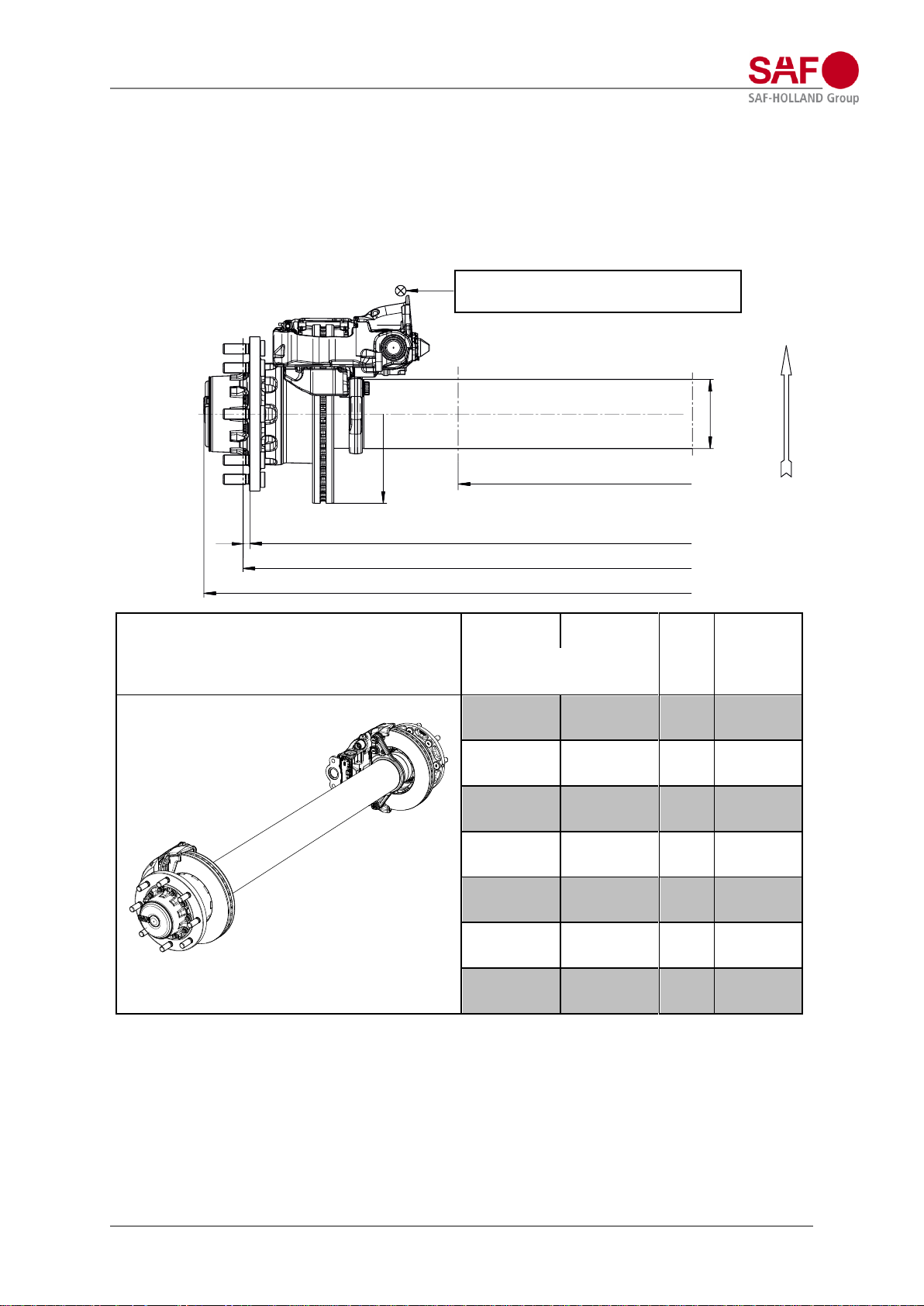
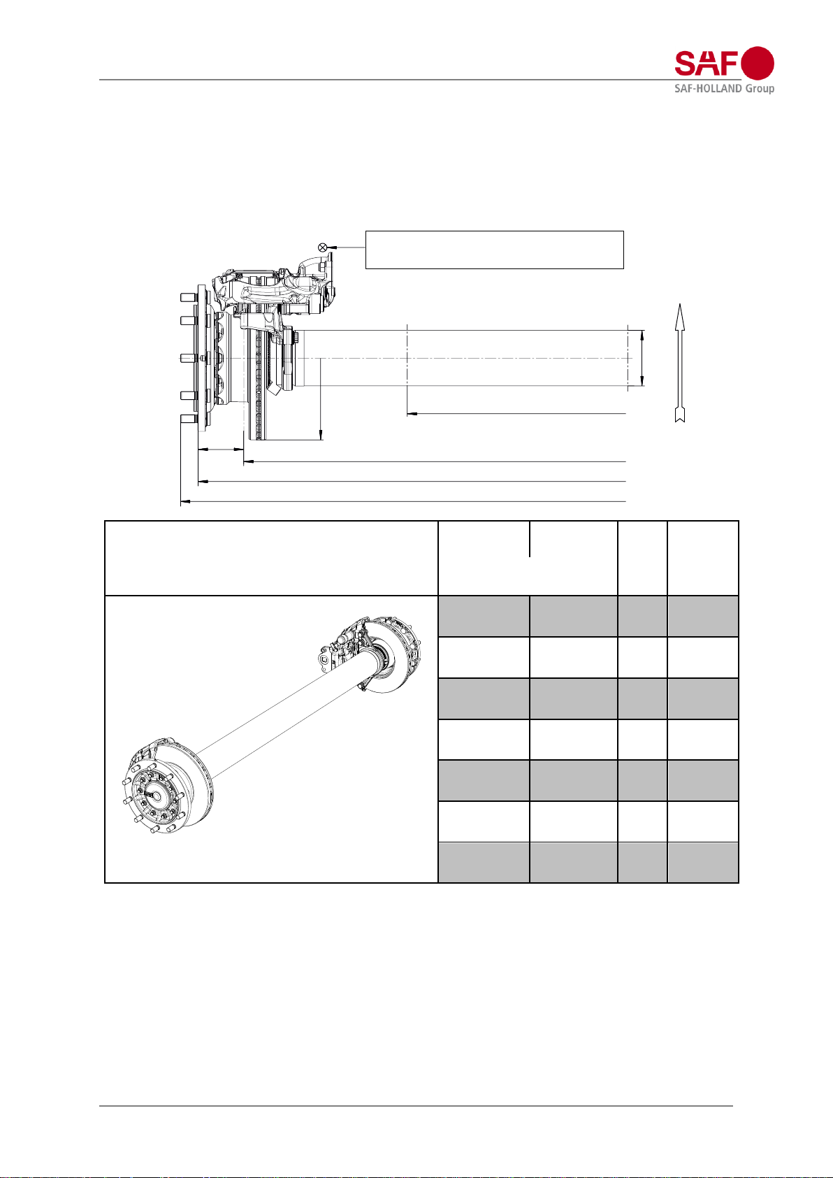
Axle version ZI9-19.:
Axle load maximum: 9.000 kg
Axle beam Ø 146 mm
Wheel fixing: 8 / 220 / 275 / 22x1,5 mm
Suitable for: Air suspension series U, MT, M, EO with single leaf trailing arm (EN) and
Air suspension series U, M with double leaf trailing arm (S)
Air bags with air bag diameter Ø 300 mm and Ø 350 mm
axle version / axle type / brake / test report
AX / LM
[mm]
S
1)
/ LM
[mm]
G
[mm]
weight
approx.
2)
[kg]
tyre (example): 245/70R19,5“
ZI9-19S / SBS1937 / SAF SBS1918 / TDB0878
ZI9-19K / SBK1937 / KNORR, SBK1937 / TDB0606
1806/900
1834/900
2004
275
1806/980 3)
1834/980 3)
2004
275
1860/950
1888/950
2058
277
1860/1020 3)
1888/1020 3)
2058
277
1926/1020
1926/1020
2124
280
1926/1050
1954/1050
2124
280
1926/1100 3)
1954/1100 5)
2124
280
1) S = AX + 2 x wheel disc thickness (standard 14 mm)
2) Axle version with SAF-HOLLAND brake calliper (SBS1918); with KNORR brake calliper (SBK1937) an
additional weight of 5 kg per axle needs to be accounted for.
Without spring seats, brake chambers and wheel nuts (spring seats are enclosed in the air suspension).
Weight deviations lie within the permitted DIN Tolerances for the respective manufacturing process.
3) with tyres 245/70R19,5“ and air bag diameter Ø 300 mm starting at V = 30 mm
Note:
When choosing the suspension assembly, the clearance between air bag (max. diameter) and chosen tyre must
be checked, this should be at least 25 mm.
Further variants on request.
Ø 146
Ø 377
12
LM – spring centre
Respect the calliper displacement of 30 mm for
adjacent parts due to the pad and disc wear
AX – distance wheel attachment faces
G – total axle width
Front
S – track
Rigid axle with disc brake
Design manual modul, Edition 2023-02 Page 27 of 133
Amendments and errors excepted.
XL-AS10004DM
-en-DE Rev
C © SAF-HOLLAND
Axle version SI11-19K:
Axle load maximum: 11.000 kg
Axle beam Ø 146 mm
Wheel fixing: 8 / 220 / 275 / 22x1,5 mm
Suitable for: Air suspension series U, MT, M, EO with single leaf trailing arm (EN) and
Air suspension series U, M with double leaf trailing arm (S)
Air bag with air bag diameter Ø 350 mm
axle version / axle type / brake / test report
AX 1) / LM
[mm]
G
[mm]
weight
approx.2)
[kg]
tyre (example):
435/50R19,5“
SI11-19K / SBK1937 / KNORR SBK1937 / TDB0605
1970/1100
2168
286
1970/1200
4,6)
2168
286
2010/1180 3)
2208
288
2040/1200 3)
2238
289
2040/1300
5,6)
2238
289
2090/1300
4,6)
2288
291
1) AX = S
2) without spring seats, brake chambers and wheel nuts (spring seats are enclosed in the air suspension).
Weight deviations lie within the permitted DIN Tolerances for the respective manufacturing process.
3) with tyres 435/50R19,5“ and air bag diameter Ø 350 mm starting at V = 30 mm
4) with tyres 435/50R19,5“ and air bag diameter Ø 350 mm starting at V = 55 mm
5) with tyres 435/50R19,5“ and air bag diameter Ø 350 mm starting at V = 70 mm
6) to be combined with air suspension types starting at a nominal ride height of 330 mm.
Note:
When choosing the suspension assembly, the clearance between air bag (max. diameter) and chosen tyre must
be checked, this should be at least 25 mm.
Further variants on request.
Ø 146
Ø 377
LM – spring centre
Respect the calliper displacement of 30 mm for
adjacent parts due to the pad and disc wear
AX – distance wheel attachment faces
G – total axle width
Front
Rigid axle with disc brake
Design manual modul, Edition 2023-02 Page 28 of 133
Amendments and errors excepted.
XL-AS10004DM
-en-DE Rev
C © SAF-HOLLAND
Axle version ZI11-19K:
Axle load maximum: 11.000 kg
Axle beam Ø 146 mm
Wheel fixing: 8 / 220 / 275 / 22x1,5 mm
Suitable for: Air suspension series U, M with double leaf trailing arm (S)
Air bags with air bag diameter Ø 350 mm
axle version / axle type / brake / test report
AX / LM
[mm]
S 1) / LM
[mm]
G
[mm]
weight
approx.2)
[kg]
tyre (example): 265/70R19,5“
ZI11-19K / SBK1937- / KNORR, SBK1937 / TDB0606
1806/900 3)
1834/900 3)
2004
280
1806/980 5)
1834/980 5)
2004
280
1860/950 3)
1888/9503)
2058
282
1860/1020 4)
1888/1020 4)
2058
282
1926/1020 3)
1954/1020
3)
2124
285
1926/1050 4)
1954/1050 4)
2124
285
1926/1100 5)
1954/1100 5)
2124
285
1) S = AX + 2 x wheel disc thickness (standard 14 mm)
2) without spring seats, brake chambers and wheel nuts (spring seats are enclosed in the air suspension).
Weight deviations lie within the permitted DIN Tolerances for the respective manufacturing process.
3) with tyres 265/70R19,5“and air bag diameter Ø 350 mm starting at V = 30 mm
4) with tyres 265/70R19,5“and air bag diameter Ø 350 mm starting at V = 55 mm
5) with tyres 265/70R19,5“and air bag diameter Ø 350 mm only with V = 70 mm
Note:
When choosing the suspension assembly, the clearance between air bag (max. diameter) and chosen tyre must
be checked, this should be at least 25 mm.
Further variants on request.
Ø 146
Ø 377
12
LM – spring centre
Respect the calliper displacement of 30 mm for
adjacent parts due to the pad and disc wear
AX – distance wheel attachment faces
G – total axle width
Front
S – track
Rigid axle with disc brake
Design manual modul, Edition 2023-02 Page 29 of 133
Amendments and errors excepted.
XL-AS10004DM
-en-DE Rev
C © SAF-HOLLAND
Axle version BI9-22…:
Axle load maximum: 9.000 kg
Axle beam Ø 146 mm
Wheel fixing: 10 / 280 / 335 / 22x1,5 mm
Suitable for: Air suspension series U, MT, M, EO with single leaf trailing arm (EN) and
Air suspension series U, M with double leaf trailing arm (S)
Air bags with air bag diameter Ø 300 mm and Ø 350 mm
axle version / axle type / brake / test report
AX / LM
[mm]
S 1) / LM
[mm]
G 2)
[mm]
weight
approx.3)
[mm]
tyre (example):
385/65R22,5“
BI9-22S / SBS2243 / SAF, SBS2220 / TDB0843
BI9-22S01 / SBS2243 / SAF, SBS2220K0 / 36102214
2210/1100
1970/1100
2302
286
2210/1200
1970/1200
2302
286
2280/1200
2040/1200
2372
288
2280/1300 4)
2040/1300 4)
2372
288
2330/1300
2090/1300
2422
290
2380/1300
2140/1300
2472
291
2380/1400 4)
2140/1400 4)
2472
291
1) S = AX – 2 x ET (120 mm)
2) G is increased by 20 mm when wheel studs are used for mounting aluminium-rims.
3) Axle version with SAF-HOLLAND brake calliper (SBS2220); with SAF-HOLLAND brake calliper (SBS2220K0)
an additional weight of 5 kg per axle needs to be accounted for.
Without spring seats, brake chambers and wheel nuts (spring seats are enclosed in the air suspension).
Weight deviations lie within the permitted DIN Tolerances for the respective manufacturing process.
4) with tyres 385/65R22,5“ and air bag diameter Ø 300 mm starting at V = 30 mm
Note:
When choosing the suspension assembly, the clearance between air bag (max. diameter) and chosen tyre must
be checked, this should be at least 25 mm.
Further variants on request.
ET 120
Ø 146
Ø 430
LM – spring centre
Respect the calliper displacement of 30 mm for
adjacent parts due to the pad and disc wear
AX – distance wheel attachment faces
G – total axle width
Front
S – track
Rigid axle with disc brake
Design manual modul, Edition 2023-02 Page 30 of 133
Amendments and errors excepted.
XL-AS10004DM
-en-DE Rev
C © SAF-HOLLAND
Axle version B9-22…:
Axle load maximum: 9.000 kg
Axle beam Ø 146 mm
Wheel fixing: 10 / 280 / 335 / 22x1,5 mm
Suitable for: Air suspension series U, MT, M, EO with single leaf trailing arm (EN) and
Air suspension series U, M with double leaf trailing arm (S)
Air bags with air bag diameter Ø 300 mm and Ø 350 mm
axle version / axle type / brake / test report
AX / LM
[mm]
S 1) / LM
[mm]
G 2)
[mm]
weight
approx.3)
[kg]
tyre (example): 385/65R22,5“
B9-22S / SBS2243 / SAF, SBS2220 / TDB0843
B9-22S01 / SBS2243 / SAF, SBS2220K0 / 36102214
2210/1100
1970/1100
2302
294
2210/1200
1970/1200
2302
294
2280/1200
2040/1200
2372
296
2280/1300 4)
2040/1300 4)
2372
296
2330/1300
2090/1300
2422
300
2380/1300
2140/1300
2472
301
2380/1400 4)
2140/1400 4)
2472
301
1) S = AX – 2 x ET (120 mm)
2) G is increased by 20 mm when wheel studs are used for mounting aluminium-rims.
3) Axle version with SAF-HOLLAND brake calliper (SBS2220); with SAF-HOLLAND brake calliper (SBS2220K0)
an additional weight of 5 kg per axle needs to be accounted for. Without spring seats, brake chambers and
wheel nuts (spring seats are enclosed in the air suspension).
Weight deviations lie within the permitted DIN Tolerances for the respective manufacturing process.
4) with tyres 385/65R22,5“ and air bag diameter Ø 300 mm starting at V = 30 mm
Note:
When choosing the suspension assembly, the clearance between air bag (max. diameter) and chosen tyre must
be checked, this should be at least 25 mm.
Further variants on request.
ET 120
Ø 146
Ø 430
LM – spring centre
Respect the calliper displacement of 30 mm for
adjacent parts due to the pad and disc wear
AX – distance wheel attachment faces
G – total axle width
Front
S – track
 Loading...