


EDL/ARF
OPERATION
INFORMATION
EDL/ARF Feature
External Dock Lock (EDL)
Automatic Reset Feature (ARF)
for Trailer Air-Ride Suspensions
XL-AR363-02 Rev. D

TABLE OF CONTENTS
Introduction..................................................................................................2
Warranty........................................................................................................2
Notes, Cautions, and Warnings .................................................................2
Table of Contents .......................................................................................2
xternal Dock Lock (EDL) Installation..................................................3
E
Suspension Ride Height Verification...............................................3
EDL Rod Flipper Plate Installation ................................................4
EDL Actuator Chamber Installation ..............................................4
ir System Connection......................................................................5
A
Operation......................................................................................................6
Automatic Reset Feature (ARF).......................................................6
Purpose:................................................................................................7
Function:..............................................................................................7
INTRODUCTION
This manual provides you information necessary for the installation,
adjustment, inspection, and safe operation of SAF-HOLLAND
External Dock Lock (EDL) Automatic Reset Feature (ARF) for
Trailer Air-Ride Suspensions.
The SAF-HOLLAND EDL is designed and engineered to provide
trouble-free service. In the event of an inoperative EDL, such as a bent
rod assembly or a damaged cam bracket, the vehicle should be driven
CAUTIOUSLY at slow speed, to the nearest service facility for repair
or replacement.
This EDL/ARF uses air drawn from the truck/tractor air system to
operate the EDL actuator. The height control valve regulates the air
pressure required for varying loads. The ARF feature ensures the
flipper plate(s) will not be trapped down (engaged position) while the
trailer is in motion.
WARRANTY
Refer to the complete warranty for the country in which the product
ranty is included with the product
will be used.
as well as in the suspension catalogs and the SAF-HOLLAND Web
Site (www.safholland.us). It may also be ordered by calling
1-888-396-6501.
A copy of
the written w
ar
Parts List ..............................................................................................7
Disengaged Application ....................................................................8
Engaged Application..........................................................................8
ARF Description when Releasing Trapped
Flipper Plates..............................................................................9
aintenance................................................................................................10
M
Auto Reset (Sensor) Valve Performance Check..........................10
EDL Flipper Plate Adjustment......................................................11
Primary Height Control Valve Information ................................12
Pilot Valve Check for EDL/ARF System....................................12
rimary Height Control Valve Adjustment..................................13
P
EDL/ARF System Troubleshooting......................................................14
NOTES, CAUTIONS, AND WARNINGS
You must read and understand all of the safety procedures presented in
this manual before starting any work on the suspension.
Proper tools must be used to perform the maintenance and repair
procedures described in this manual. Many of these procedures require
special tools.
Failure to use the proper equipment could result in
personal injury and/or damage to the suspension.
Safety glasses must be worn at all times when performing the
procedures covered in this manual.
Throughout this manual, you will notice the terms “NOTE,”
“IMPORTANT,” “CAUTION” and “WARNING” followed by
important product information. So that you may better understand the
manual, those terms are as follows:
NOTE: Includes additional information to enable accurate and
easy performance of procedures.
IMPORTANT: Includes additional information that
if not followed could lead to hindered
product performance.
Used without the safety alert symbol,
indicates a potentially hazardous situation
hich, if not avoided, may result in
w
.
e
operty dama
pr
Indicates a potentially hazardous situation
h, if not a
hic
w
moderate injury.
Indica
which, if not avoided, could result in death or
serious injury.
g
oided, may result in minor or
v
tes a potentiall
y hazar
dous situa
XL-AR363-02 Rev. D2
tion

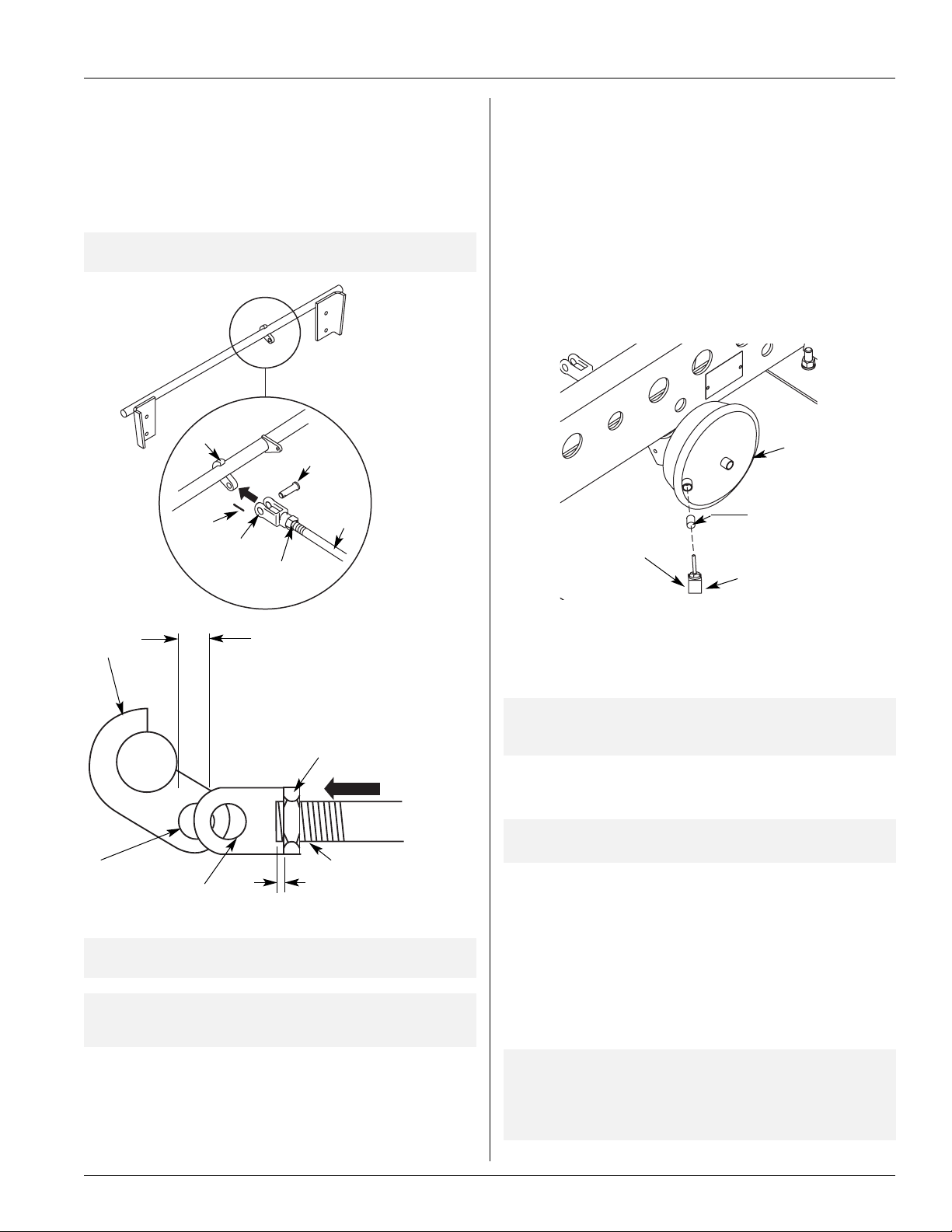
EXTERNAL DOCK LOCK (EDL) INSTALLATION
FIGURE 1
EDL Components
1
3
9
4
3
2
ITEM
NO. DESCRIPTION NS-xxx-16.0* NS-xxx-16.5* NS-xxx-17.0* NS-xxx-18.0* QTY.
1 EDL Rod Assembly 42˝ - 90546178 42˝ - 90546270 42˝ - 90546136 42˝ - 90546138 1
48˝ - 90546177 48˝ - 90546269 48˝ - 90546132 48˝ - 90546134
2 Hex Bolt 38 -16 x 1˝ 93002571 93400471 93400471 93400471 4
3 EDL Rod Support Plate 90034494 90034494 90034494 90034494 2
4 Hex Lock Nut 3/8˝ - 16 93400472 93400472 93400472 93400472 4
5 Hex Nut .50-13 93400136 93400136 93400136 93400136 2
6 Washer .53 93600072 93600072 93600072 93600072 2
7 EDL Actuator Chamber 90546122 90546122 90546122 90546122 1
8 Choke Valve 90054811 90054811 90054811 90054811 1
1
9
/2˝
Clevis Assembly w/1/2˝ Pin
* “xxx” denotes models 400 or 450.
IMPORTANT: Be certain the correct EDL assembly for the
11M018-8 11M018-8 11M018-8 11M018-8 1
NOTE: Example: NS-400/450-4818, last two digits
suspension ride height is being installed. Various
5
6
8
represent 18˝ (457mm) ride height.
7
suspension ride heights require different
assemblies with different flip plate heights. If
unsure of ride height, see
FIGURE 3 and Table 1
or call SAF-HOLLAND Customer Service at
1-888-396-6501.
Suspension Ride Height Verification
1. Verify ride height by checking serial number tag located on the rear
crossmember (
If the serial number tag is not legible or unavailable, verify ride height
FIGURE 2).
2. Compare ride height to corresponding Flipper Plate Height from
Table 1 below (FIGURE 3).
TABLE 1.
Model No. Height Height
NS-400/450-16 16˝ (406mm) 6.5˝ (165mm)
NS-400/450-16.5
NS-400/450-17 17˝ (432mm) 7.5˝ (191mm)
NS-400/450-18
Ride Flipper Plate
16.5˝ (419mm) 7.0˝ (178mm)
18˝ (457mm)
“A”
8.5˝ (216mm)
by measuring from the center of the axle to the bottom of the frame
or slider (
FIGURE 2
FIGURE 3).
FIGURE 3
Flipper Plate
Serial Tag Location
Serial Number T
on Rear Crossmember
ag Located
Flipper Plate Height
“A”
Ride
Height
XL-AR363-02 Rev. D 3
5/8˝ (16mm)
Min.
Clearance

EXTERNAL DOCK LOCK (EDL) INSTALLATION continued
EDL Rod Flipper Plate Installation
. Attach one support plate to frame rail above rear axle, and secure
1
with two bolts and nuts.
FIGURE 4
EDL Rod Support Plate
EDL Rod Support Plate
Bolts
2. Slide one end of EDL Rod Assembly into the hole of the attached
support plate. Then slide the other support plate onto the opposite
end of EDL Rod Assembly and secure with two bolts and nuts.
Tighten and torque all four bolts and nuts to 25 ft. lbs. (34 Nm)
FIGURE 5).
(
FIGURE 5
EDL Installation
DO NOT tighten (FIGURE 4).
Nuts
IMPORTANT: EDL Rod/Flipper Plate Assembly should rotate
reely without binding (
f
IGURE 6).
F
FIGURE 6
Flipper Plate Installation
IMPORTANT:
EDL Flipper Plate
Assembly should
otate fully without
r
binding
IMPORTANT:
Flipper Plate must
be completely down
when attaching
actuator push rod
5/8˝ Min. (16mm)
Clearance Gap Required
IMPORTANT: Both flipper plates must rest on equalizing beam
when trailer is loaded.
EDL Actuator Chamber Installation
1. Attach actuator chamber to mounting bracket on slider box
crossmember (
Torque nuts to 50-60 ft. lbs. (68-81 Nm).
FIGURE 7
Actuator Chamber Installation
FIGURE 7). Fasten with two lock washers and nuts.
Bolts
Support Plate
Nuts
Flipper Plate
Tab
Cam Bracket
EDL Rod Assembly
Nut
Lockwasher
Actuator
Chamber
To air supply line
Actuator Chamber
Mounting Bracket
Install the adjusting nut and c
2.
vis to the actua
le
tor push rod and
thread adjusting nut and clevis down the push rod. Be sure to leave
clevis 1/2˝ (13mm) short of cam mounting hole (
FIGURE 8).
continued
XL-AR363-02 Rev. D4
EXTERNAL DOCK LOCK (EDL) INSTALLATION continued
3. Pull actuator push rod out (arrow A) so the hole in the cam aligns
ith the clevis hole (this creates tension on the actuator spring to help
w
keep the flipper plate completely down). Install clevis pin and secure
with cotter pin (
FIGURE 8).
FIGURE 8
Clevis Installation
IMPORTANT: Flipper Plate must be completely down when
attaching actuator push rod.
Cam
Cotter
Pin
Clevis
Adjusting
Jam Nut
Clevis
Pin
Push
Rod
Air System Connection
. The control for releasing the EDL is the same for releasing the
1
emergency brakes on the trailer. Locate a trailer supply line (usually
red) at the point it enters the spring brake valve (supply port).
. Replace straight connector fitting with a tee and reconnect the
2
upply line and add a length of plastic line for connection to the
s
actuator chamber (
connects the cylinder port of the pilot valve to the bottom port of
the sensor valve (
FIGURE 9
Connect Air System
To supply line
connection on
sensor valve
FIGURE 9) and the line that you will install which
FIGURE 10).
Actuator
Chamber
Choke Valve
Air Line Fitting
Cam
Bracket
Adjust clevis and jam nut on
push rod so clevis mounting hole
is 1/2˝ (13mm) short of cam
mounting hole to cause tension
on actuator return spring
Adjusting Jam Nut
“A”
Cam Mounting Hole
Clevis Mounting Hole
IMPORT
ANT:
Adjust the push r
is completel
y do
wn (
Actuator Push Rod
3/16˝ (4.76mm)
Maximum actuator
push rod protrusion
od length to assure f
FIGURE 6).
lipper plate
IMPORTANT: EDL Rod/Flipper Plate Assembly should rotate
y without binding after attaching actuator
eel
fr
od (
push r
FIGURE 6).
3. At the threaded end of the 1/4 N.P.T. tube fitting insert the choke
valve (supplied) and install fitting to actuator. Attach the supply line
from the brake valve to a 1/4 N.P.T. tube fitting (FIGURE 9).
NOTE: It may be necessary to use a vise to press choke valve
into tube fitting or use a hammer and gently tap choke
valve into tube fitting.
4. Insert the 1/4 N.P.T. tube fitting into the brake actuator inlet port
FIGURE 9).
(
NOTE: Choke valve should be flush with bottom of
the fitting.
5. From the pressure protection valve, run a line to the bottom port of
the primary height contr
ol valve (
FIGURE 12).
6. Connect the top port of the primary height control valve to the
center port of the sensor valve (
the primary height control valve and sensor
he center por
T
7.
v
alve are connected to the air springs (
ts of
FIGURE 11).
FIGURE 11).
8. The pilot port of the pilot valve is connected to the emergency line
(
FIGURE 12).
Secur
e all suppl
y lines and check for air leaks.
IMPORTANT: It is the responsibility of the air system installer
to secure all air lines and check for any air leaks.
If air leaks are detected, repair as required.
ailure to eliminate the air leaks may compromise
F
.
mance
the suspension perf
or
XL-AR363-02 Rev. D 5

OPERATION
Automatic Reset Feature (ARF)
he Automatic Reset Feature (ARF) is designed to ensure that the
T
External Dock Lock (EDL) flipper plates are not trapped down while
the trailer is being operated. This is accomplished by the use of two
valves. A pilot valve is used to monitor emergency brake pressure to
determine if the trailer is parked or in motion. A sensor valve is used
to monitor the position of the EDL flipper plates (either up or down)
FIGURE 10).
(
FIGURE 10
Sensor Valve Detail
Sensor
Valve
Check Valve
The primary height control valve has full function under two
conditions: (1) parking brakes are engaged or disengaged with flipper
lates up or (2) parking brakes are engaged with flipper plates down.
p
however, parking brakes are disengaged with flipper plates
down, the sensor valve will add air directly to the air springs.
fter the air springs have sufficient air pressure to raise the flipper
A
plates up off the load pads, the flipper plates rotate up and out of the
way. This disengages the sensor valve and allows the primary height
control valve to resume full function (
FIGURE 12).
NOTE: For further ARF information contact SAF-HOLLAND
Customer Service at 1-888-396-6501.
f
I
Emergency
Line
Pilot Valve
FIGURE 12
Automatic Reset Feature
To actuator
chamber
FIGURE 11
Primary Height Control Valve Detail
Primary Height Control Valve
To air springs
Primary Height
Control Valve
To center port
of sensor valve
To PPV
To pilot
valve
To air springs
Sensor Valve
Check Valve
Air Reser
voir Tank
Pressure Protection V
Flipper Plate
alve
Link
Emergency Line
Pilot V
alve
o Actuator
T
Chamber
XL-AR363-02 Rev. D6

OPERATION continued
Purpose:
he ARF (Automatic Reset Feature) is designed to ensure that the
T
External Dock Lock (EDL) flipper plates will not be trapped down
(engaged position) while the trailer is in motion. This is accomplished
by the use of two additional system valves.
OTE:Refer to (FIGURE 13)for component locations in the
N
EDL/ARF system.
FIGURE 13
EDL/ARF System
Piping Diagram
(Numbers correspond
to the Parts List below)
43/4˝±1/8˝
(120.65±
3.18mm)
Tab
8
Must use
Nylok
1/4˝-20 nut
(2 places)
11 Linkage
ssembly
A
Function:
Because both vehicle motion and position of the flipper plates must be
monitored, two additional system valves are used along with the height
control valve. A pilot valve monitors emergency brake pressure to
determine if the vehicle is parked or in motion. An auto reset (sensor)
alve monitors the position of the flipper plates (up or down) on the
v
External Dock Lock (EDL).
IMPORTANT: The sensor valve is not interchangeable with
the HCV.
4
5
From emergency
brake line
10
7 EDL Actuator
2
6
9
EDL Flipper Plate Rod Assembly
shown in engaged (down) position.
Parts List
1. EDL Flipper Plate (Shown in the Engaged Position):
The flipper plates are activated by the vehicle’s emergency parking
brakes. When the parking brakes are engaged, the flipper plates
rotate down to the engaged position. When the parking brakes are
eleased, the f
r
2. Primary Height Control Valve (1/4˝ and 3/8˝ air lines):
he Primar
T
adjusted to suspension design ride height to assure proper air
suspension and EDL function. When the flipper plates are up, the
primar
3. Pilot Valve: A pilot valve is used to monitor emergency brake
pressure to determine if the trailer is parked or in motion.
Auto Reset (Sensor) Valve:
4.
used to monitor the position of
or down). (To distinguish between a sensor valve and an HCV, a
sticker is placed on the sensor valve.) When the flipper plates are
in the up position, the standard height control valve maintains the
predetermined ride height. The auto reset (sensor) valve arm
should only be in the “up” position when the flipper plate is
down, or “down” when the flipper plate is in the up position.
Anytime this valve is in the neutral position it will cause the air
system to malfunction.
5. One-Way Check Valve (1/4˝ and 3/8˝ air lines): Installed
to the middle por
lipper plates rotate up to the disengaged position.
y Height Control Valve must always be properly
y height control v
alve has full function.
the sensor valve.
t of
An auto r
the EDL f
eset (sensor) valv
lipper plates (either up
e is
3
1
6. Pressure Protection Valve: Air pressure protection valve
ensures that safe air brake pressure is always maintained (70
psig—4.8 bars) in the air reservoir.
7. EDL Actuator: Push rod retracts (with emergency brakes on) to
pull flipper plates down (engaged).
8. Air Reservoir: Main vehicle air supply.
9. Air Spring: When the emergency brakes are released, air is
supplied to the air springs, raising the trailer above ride height.
This frees the trapped flipper plates on the trailing arm load pads.
lipper plates will then rotate up and out of the way. The
he f
T
rotation upward of the flipper plates, rotates the arm of the
sensor valve downward. This disengages the sensor valve and
ws the primary height contr
allo
ol v
e to contr
alv
ol all air flow for
ride height.
10. Choke Valve: Can be installed in either side of the air
y line to the actuator. Purpose of choke valve is to slow
suppl
down flipper plate rotation.
11. Auto Reset (Sensor) Valve Linkage Assembly:
Predetermine length of 4 3/4˝±1/8˝ (120.65±3.18mm) ensures
proper function of system. Linkage fasteners must be assembled
e.
v
bo
wn a
as sho
XL-AR363-02 Rev. D 7

OPERATION continued
N.C. Port
Cylinder
Port
N.O.
Port
Exhaust To
Atmosphere
Pilot (Top)
Port to
Emergency
Brake Line
Exhaust
Air Spring
Air
Reservoir
Air Spring
Pressure Protection Valve
Minimum of 75 psig (5.2 bars) to allow
Air to Flow through Valve
Primary
Height
Control
Valve
Auto
Reset
(Sensor)
Valve
Air Spring
Air Spring
One-Way
Check
Valve
EDL Flipper Plate
Disengaged (Up) Position
Pilot
Valve
EDL
Actuator
Disengaged Application
DL Flipper plates up (disengaged) and vehicle is in
E
motion (FIGURE 14).
When the parking brakes are disengaged, the flipper plates will be up
and the primary height control valve (HCV) has full function. The
rimary HCV fills the air springs through its center port and exhausts
p
he air springs through the top port of the auto reset (sensor) valve
t
FIGURE 15).
(
FIGURE 14
EDL
Disengaged
Flipper Plate
Disengaged
(Up Position)
Engaged Application
EDL Flipper plates down (engaged) and vehicle is
parked
1. Releasing air pressure from the trailer brake system or
disconnecting the glad hand engages the parking brakes.
FIGURE 16
EDL Engaged
Flipper Plate
Engaged
(Down
Position)
2. System pressure to the “pilot port” of the pilot valve is cut off.
3. The normally closed (N.C.) port of the pilot valve closes, cutting off
system pressure.
4. The normally open (N.O.) port of the pilot valve opens, providing
an exhaust port for the air between the pilot valve and the EDL
actuator and sensor valve to escape.
5. The HCV maintains the ride height.
6. The EDL actuator push rod retracts, rotating the EDL rod assembly
so the flipper plates are down—in the engaged position.
7. If the suspension is at the correct ride height, the bottom edge of the
flipper plates
down position and the ARF does not function. Trailer and
suspension component damage could result. Refer to
EDL/ARF System Troubleshooting on page 14.
must be 5/8˝ above the beam load pads.
Do not operate vehicle (put in motion)
if flipper plates are trapped in the
FIGURE 15
EDL/ARF Piping Diagram with Flipper Plates Disengaged (up position)
XL-AR363-02 Rev. D8

OPERATION continued
N.C. Port
Cylinder
Port
N.O.
Port
Exhaust To
Atmosphere
Pilot (Top)
Port to
Emergency
Brake Line
Exhaust
Air Spring
Air
Reservoir
Air Spring
Pressure Protection Valve
Minimum of 75 psig (5.2 bars) to allow
Air to Flow through Valve
Primary
Height
Control
Valve
Auto
Reset
(Sensor)
Valve
Air Spring
Air Spring
One-Way
Check
Valve
EDL
Flipper
Plate
Engaged
(Down) Position
Pilot
Valve
EDL
Actuator
ARF Description when Releasing
Trapped Flipper Plates
Trapped flipper plates in the down (engaged)
position (FIGURE 17)
1. With parking brakes disengaged, the air reservoir begins to fill with
air. When air reservoir pressure reaches 85 psig (5.9 bars), the
pressure protection valve opens, supplying air to the
suspension system.
2. System pressure is supplied directly to the height control valve
(HCV) and to the normally closed (N.C.) port of the pilot valve.
. As brake system pressure increases, pressure increases to the top
3
port or “pilot port” of the pilot valve.
4. Increased pressure to the “pilot port” opens the N.C. port of the
pilot valve, applying system pressure through the cylinder port to the
sensor valve and the EDL actuator chamber.
5. System pressure to the EDL actuator chamber in turn pushes the
actuator push rod—which is fastened to the EDL rod assembly by a
clevis and pin—attempting to rotate the
flipper plates up (out of the way).
6. At the same time system pressure is applied to the EDL actuator
hamber, air also flows through the sensor valve and one-way check
c
valve. Air flowing through the check valve into the air springs
temporarily raises the slider box. With the slider box raised—freeing
the “trapped” flipper plates—the actuator push rod rotates the
lipper plates up.
f
7. After quickly releasing the flipper plates, the HCV returns the
suspension to its normal ride height. To return to the normal ride
height, increased air pressure from the air springs exhausts through
he HCV and out through the sensor valve top port.
t
FIGURE 17
Trapped
Flipper Plate
Trapped
Flipper
Plate
FIGURE 18
EDL/ARF Piping Diagram with Flipper Plates Engaged (down position)
XL-AR363-02 Rev. D 9

MAINTENANCE
Auto
Reset
(Sensor)
Valve
Auto Reset (Sensor) Valve Performance Check
To check the Sensor Valve for proper adjustment and
operation, perform the following procedures.
Failure to chock tires prior to beginning
maintenance could allow vehicle rollaway
hich, if not avoided, could result in death or
w
serious injury.
NOTE: Apply air system pressure in excess of 85 psig (5.9 bars)
before doing performance check.
. Disconnect the auto reset (sensor) valve lower linkage connection to
1
the EDL rod assembly. Rotate valve arm up approximately 20˚ and
FIGURE 19). Air should flow through one-way check valve
hold (
ports to air springs (
2. Move valve arm down 20˚ (
primary height control valve upper linkage connection. Rotate
primary height control valve arm down approximately 45˚ and hold
for 5-10 seconds. Air should flow (exhaust) out top port of auto
reset (sensor) valve (
3. Reconnect sensor valve and primary height control valve linkages.
sensor valve ONLY. Use of primary height control valve
(1/4˝ [6.35mm] or 3/8˝ [9.53mm] air lines) in place of
sensor valve will result in malfunction of the auto reset
feature and possible damage to suspension and/or trailer.
NOTE: To prevent side loading on sensor valve linkage
connection—fastening hardware
shown in (
assembled as shown, disconnect linkage assembly and
refasten as shown.
FIGURE 21
Auto Reset Sensor V
FIG. 19).
FIGURE 20) and hold. Disconnect the
FIGURE 20).
In the event replacement of the
sensor valve is necessary, replace with
MUST be assembled as
FIGURE 21) for proper function. If not
alve Linkage Assembly
FIGURE 19
Auto Reset (Sensor) Valve (EDL Engaged) Air Flow
Check
Valve Arm in up position
(above horizontal)
Bottom Port
EDL Rod Assembly
Air should be
flowing out of
both check
valve ports
To Air
Springs
Disconnect
Lower
Linkage
Tab
FIGURE 20
Auto Reset (Sensor) Valve Air Flow Check
Air should exhaust
out top port of
sensor valve
Auto
Reset
(Sensor)
Valve
Sensor Valve
Arm down 20˚
below horizontal
Sensor
alve
V
Arm
ab
T
Link - Must
be vertical
to prevent
side loading
43/4˝±1/8˝
(120.65±
3.18mm)
Must use Nylok
1/4˝-20 nut (2
places)
Flat Washers
Nylok Nut
Shoulder
Bolt
Tab
Flat
Washers
Sensor
Valve Arm
Nut Slot
Nylok
Nut
Sensor
Valve
Shoulder
Bolt
EDL Rod
Assembly
Primary
Height
Control
Valve
Hold Primar
45˚ below horizontal for
10-15 seconds
y HCV Arm down
Disconnect upper
linkage connection
Air
Spring
XL-AR363-02 Rev. D10

MAINTENANCE continued
Auto
Reset
(Sensor)
Valve
EDL
Flipper
Plate
Disengaged (Up) Position
EDL
Actuator
Auto
Reset
(Sensor)
Valve
EDL
Flipper
Plate
Engaged
(Completely Down) Position
EDL
Actuator
EDL Flipper Plate Adjustment
Proper EDL Flipper Plate/Auto Reset (Sensor) Valve
Arm Adjustment
ailure to chock tires prior to beginning
F
aintenance could allow vehicle
m
rollaway which, if not avoided, could result in death or
serious injury.
. With the emergency brakes applied visually check the EDL Flipper
1
Plates and valve arm for correct positioning (
positioning is found move ahead to Step 4.
ORRECT Flipper Plates Engaged (Down) Position
C
mergency Brakes APPLIED:
E
When the EDL is engaged and properly installed/adjusted the valve
arm will be approximately 20˚ above the horizontal position, and
the flipper plates will be in the completely down
position (
FIGURE 22).
EDL/ARF System could malfunction if
the flipper plates and sensor valve arm
are not in the correct alignment to each other. If operated
under incorrect alignment—trailer and/or property
damage could result.
2. If upon inspection the flipper plates do not rotate to the complete
down position and the sensor valve arm is not approximately 20˚
above horizontal position, the actuator push rod must be adjusted.
Remove clevis pin, loosen jam nut, and thread the clevis in until the
push rod will pull the EDL flipper plates to the straight down
position and push the valve arm approximately 20˚ above
horizontal position.
IMPORTANT: When adjusting flipper plates to the straight
down position, clevis must be threaded in 1/2˝
(13mm) short of cam mounting hole (
24
). This creates tension on the actuator return
spring to pull the flipper plates completely down
during the engaged application.
3. Pull actuator push rod out so the hole in the cam aligns with the
clevis hole. Install clevis pin and secure with cotter pin
FIGURE 24). Tighten jam nut against clevis.
(
NOTE: Maximum push rod protrusion is 3/16˝ (4.76mm)
FIGURE 24).
(
4. With the emergency brakes OFF visually check the EDL flipper
plates and sensor valve arm for correct positioning (
FIGURE 22). If correct
FIGURE
FIGURE 23).
FIGURE 22
CORRECT Flipper Plate Engaged Position
Valve Arm up 20˚
(above horizontal)
Tab
Adjusting
Cam
Clevis
Jam Nut
Actuator
Push Rod
FIGURE 23
CORRECT Flipper Plate Disengaged Position
Valve Arm down 20˚
(below horizontal)
Cam
43/4˝±1/8˝
(120.65±3.18mm)
Actuator
Tab
Push Rod
FIGURE 24
EDL Cam to Actuator Push Rod Adjustment
Cam
Bracket
1/2˝
(13mm)
Leave clevis 1/2˝ (13mm) short of
cam mounting hole to preload
spring in chamber assembly
CORRECT Flipper Plates Disengaged (UP) Position
gency Brakes OFF:
Emer
Adjusting Jam Nut
When the EDL is disengaged and properly installed/adjusted the
sensor valve arm will be down approximately 20˚ below horizontal
position and the f
(
FIGURE 23).
lipper pla
IMPORTANT: If
Engaged or Disengaged positioning, by adjusting
the actua
SAF-HOLLAND Customer Service.
XL-AR363-02 Rev. D 11
tes will be in the up position
e unable to obtain either the correct
ou ar
y
tor push r
od (
FIGURE 22),
contact
Cam
Mounting
Hole
Clevis Mounting Hole
3/16˝ (4.76mm)
Maximum actuator
push rod protrusion
IMPORTANT: Flipper plate must be completely down
(engaged position).

MAINTENANCE continued
Primary Height Control Valve Information
Height Control Valve Performance Check
IMPORTANT: Proper inspection can eliminate unnecessary
replacement of height control valve.
FIGURE 25
Height Control Valve Performance Check
NOTE: Apply air system pressure in excess of 85 psig
5.9 bars) before doing performance check.
(
1. Disconnect the link assembly from height control valve arm.
. Move control arm up 45˚ for 10-15 seconds – air should flow to air
2
springs (
3. Move control arm to center (neutral) position – valve should shut
off air flow to air springs.
4. Move control arm down 45˚ for 10-15 seconds (
should f
and exhaust out the top port of the auto reset (sensor) valve.
5. Move control arm to center (neutral) position – valve should shut
off air flow.
6. Valve is good if performance is as noted.
7. Reconnect upper link assembly to control arm.
FIGURE 25).
FIGURE 25) - air
low from air springs into center port of height control valve
Pilot Valve Check for EDL/ARF System
Pilot Valve Performance Check
NOTE: Apply air system pressure in excess of 85 psig (5.9 bars)
before doing performance check.
Central
(Neutral)
Position
Intake
Up 45˚
Exhaust
Down 45˚
NOTE: If valve does not perform correctly, refer to the
adjustment procedures on page 13.
FIGURE 26
Pilot Valve Check
1. When air from emergency brakes is present on top port of pilot
valve air should flow from N.C. port to cylinder port (
2. When emergency spring brakes are released (no air to top port of
pilot valve, air should exhaust (quickly) from EDL actuator out of
t (
por
.
.O
N
FIGURE 26).
FIGURE 26).
Pilot Port to
Emergency
Brake Line
Pilot Valve
Cylinder Port
N.O. Port
Exhaust to
Atmosphere
N.C. Port
XL-AR363-02 Rev. D12

MAINTENANCE continued
Primary Height Control Valve Adjustment
Height Control Valve Adjustment Procedures
IMPORTANT: This adjustment procedure is for ONE Height
Control Valve system with an External Dock
Lock Device
. Prior to adjustment, the vehicle must be in an unladen condition on
1
a level floor and supported on a king pin stand or coupled to a
tractor (
FIGURE 27).
Failure to properly support suspension
during maintenance may allow
suspension to fall which, if not avoided, could result in
eath or serious injury.
d
IMPORTANT: DO NOT use flipper plate height plus 5/8˝
(16mm) clearance spacing to determine ride
height setting.
2. Verify ride height by checking serial number tag located on the frame
bracket or crossmember (FIGURE 28).
Example: NS400/450-4816, last two digits
represent 16˝ (406mm) ride height.
3. Confirm proper EDL flipper plate rod assembly by comparing
predetermined ride height to corresponding EDL flipper plate
FIGURE 29, see chart).
height (
4. Disconnect primary height control valve linkage to lower mounting
bracket, and move control arm up 45˚ and hold for 10-15 seconds to
raise vehicle. Return control arm to center (neutral) position.
5. Move control arm down 45˚ and hold until system air exhausts
completely, lowering flipper plates. Return control arm to center
(neutral) position, and check for proper ride height (determined in
step 2—
FIGURE 29).
FIGURE 27
Trailer Supported at Fifth Wheel Height
Operating
Height
Support at King Pin
FIGURE 28
Serial Tag
FIGURE 29
Obtaining Proper Ride Height
Flipper Plate
“A”
Ride
Height
Ride
Height
C
L
Axle
Serial Number Tag
Located on Rear
Crossmember
5/8˝ MIN.
(16mm)
Clearance must
be maintained
between
bottom of
flipper plates
and beam pads.
6. Insert the locating pin into the adjusting block and bracket on the
height control valve (
nut located on the adjusting block (
FIGURE 30). Loosen the 1/4˝ adjusting lock
FIGURE 30), allowing the
control arm to move up and down approximately 1˝ (25mm).
Replace lower link bolt back into lower link and mounting bracket.
DO NOT fasten.
7. Tighten adjusting loc
ut at the adjusting b
k n
lock to 30-40 in. lbs.
(3.75-5 Nm), and remove locating pin inserted in Step 6.
8. Remove lower link bolt, and raise control arm 45˚ and hold for
10-15 seconds (
FIGURE 30). T
his will raise the vehicle. Bring the
control arm back to center (neutral) position.
9. Reconnect linkage to lower mounting bracket and fasten connection.
NOTE: If the suspension returns to a dimension less than
design ride height,
adjust (up) so suspension will al
ride height.
loosen the 1/4˝ adjusting nut and
n to its cor
etur
ys r
a
w
r
NEVER LESS THAN DESIGN HEIGHT.
ect
RIDE “A”
HEIGHT
16.0˝ (406mm) 6.5˝ (165mm)
16.5˝ (419mm) 7.0˝ (178mm)
17.0˝ (432mm) 7.5˝ (191mm)
18.0˝ (457mm) 8.5˝ (216mm)
FIGURE 30
Primary Height Control Valve
45˚ Intake
(Up)
Control
Arm
45˚ Exhaust
(down)
Exhaust (Top Port)
For EDL/ARF applications,
line is run to Sensor V
top port
To Air Springs
(Always Center Port)
alve
Supply (Always Bottom Port)
FLIPPER PLATE HEIGHT
1/4˝ Adjusting
Lock Nut
Adjusting
Block
Locating Pin
(Remove After
Adjustments)
XL-AR363-02 Rev. D 13

EDL/ARF SYSTEM TROUBLESHOOTING
Failure to chock tires prior to beginning
maintenance could allow vehicle rollaway
which, if not avoided, could result in death or
erious injury.
s
IMPORTANT: Apply air system pressure in excess of 85 psig
(5.9 bars) before doing any performance checks.
PROBLEM POSSIBLE CAUSE and REMEDY
Incorrect plumbing of the sensor valve. Check and repair as required.
(See pages 7 and 10.)
One-way check valve malfunction. Check and repair or replace as required.
(See page 8.)
Air is continually leaking
out the exhaust port of the
sensor valve.
Trailer is at full extension
and suspension is pulling
on shock absorber.
Flipper plates are trapped
in the down position.
Flipper plates will not Cam bracket that connects to EDL actuator Repair or replace as required.
swing down completely. is damaged or weld is broken.
EDL actuator or sensor valve malfunctioning. Check and repair or replace as required.
(See pages 7 to 11.)
Primary HCV mis-adjusted or malfunctioning. Check and repair or replace as required.
(See pages 12 and 13.)
Pilot valve malfunctioning. Check and repair or replace as required.
(See page 12.)
Diaphragm on EDL actuator ruptured. Replace as required. (See pages 4 and 5.)
Sensor valve linkage is the wrong length. Replace linkage with Linkage Ass’y.
(See FIGURE 21, page 10.) (See pages 7 and 10.)
No air flow out of pressure protection Check specified air pressure. Minimum
valve from the air reservoir. 70 psig (4.8 bars) required in air reservoir.
EDL actuator or sensor valve mis-adjusted Check and adjust or replace as required.
or malfunctioning. (See pages 7 to 11.)
Pilot valve malfunctioning. Check and repair or replace as required.
(See pages 8 and 12.)
Push rod of EDL actuator is bent. Replace as required. (See pages 4 and 5.)
Cam bracket that connects to EDL actuator Repair or replace as required.
is damaged or weld is broken.
Diaphragm on EDL actuator ruptured. Replace as required. (See pages 4 and 5.)
Sensor v
(See FIGURE 21, page 10.) (See pages 7 and 10.)
No air f
valve from the air reservoir. Minimum70 psig (4.8 bars) required
No air flo
Vehicle overloaded or unevenly loaded. Check wheel loads and correct as needed.
Primary HCV mis-adjusted or malfunctioning. Check and repair or replace as required.
Trailer not at proper ride height. Check and adjust if needed.
alve linkage is the wrong length. Replace linkage with Linkage Ass’y.
e protection Check specified air pressure.
low out of
w to
pressur
ARF system pilot v
in air reservoir.
alve. Check for breech in air supply line and
repair/replace as required. (Pgs 6, 7, & 12.)
es 12 and 13.)
g
(See pa
(See pages 12 and 13.)
Ride height set improperly (too low). See pages 12 and 13.
Actua
tor push r
od needs adjustment.
Need 5/8˝ (25mm) g
ap.
XL-AR363-02 Rev. D14

NOTES
XL-AR363-02 Rev. D 15

Engineering Your Road to Success
SAF-HOLLAND USA,
888.396.6501
800.356.3929
ax
F
Inc
.
SAF-HOLLAND Canada Limited
519.537.3494
Western Canada
604.574.7491
800.565.7753
ax
F
Fax 604.574.0244
Copyright © J
anuary 2008-SAF-HOLLAND
, Inc. All information contained in this document was correct at time of copyright, and is subject to change without notice. All rights reserved.
www.safholland.us
XL-AR363-02 Rev. D16
 Loading...