

Saeco GROUP 700-SINGLE BOILER PLUS, GROUP 700-SINGLE BOILER, GROUP 700-ESPRESSO DOUBLE BOILER PLUS, GROUP 700-ESPRESSO DOUBLE BOILER User Manual

Automatic beverage vending machine
Espresso Italia PTY LTD
www.espressoitalia.com.au
Freecall 1300 660 976
Saeco Group 700 NEW
Model:
ESPRESSO DOUBLE BOILER
ESPRESSO DOUBLE BOILER PLUS
SINGLE BOILER
SINGLE BOILER PLUS
TYPE: SG700NTYPE: SG700N
TYPE: SG700N
TYPE: SG700NTYPE: SG700N
6
TION AND MAINTENANCETION AND MAINTENANCE
TION AND MAINTENANCETION AND MAINTENANCE
TION AND MAINTENANCE
OPERAOPERA
OPERAOPERA
OPERA

English
Espresso Italia PTY LTD
www.espressoitalia.com.au
Freecall 1300 660 976
MAIN PARTS
10
7
8
9
2
4
1
5
3
6
1 Brew group and coffee grinder
2 Vending machine unit
3 Sugar dispensing unit
4 Electronic card
5 Cup dispenser
6 Coiner unit
7 Tray socket
8 Data plate
9 Data plate showing the minimum and
maximum water pressure
10 Water mains connection
2
English
Espresso Italia PTY LTD
www.espressoitalia.com.au
Freecall 1300 660 976
TABLE OF CONTENTS
1 - INTRODUCTION TO
THE MANUAL......................
1.1 Foreword ............................................ 4
1.2 Symbols used .................................... 4
1.3 General instructions…………..............5
1.4 Operator requirements ....................... 7
2 - TECHNICAL
SPECIFICATIONS..................
3 - SAFETY STANDARDS ............ 8
3.1 Foreword ............................................ 8
3.2 General safety rules ........................... 8
4 - HANDLING AND
STORAGE.............................
4.1 Handling and transport........................9
4.2 Storage .............................................. 10
4.3 Packaging .......................................... 10
4
7
9
7 - PROGRAMMING................. 27
7.1 Machine software updating through
eprom ................................................ 31
7.2 Description of functions ...................... 31
8 - SERVICE .............................. 40
9 - MAINTENANCE AND
INACTIVITY.........................
9.1 Cleaning and loading .......................... 42
9.1.1 Daily cleaning .................................... 42
9.1.2 Weekly cleaning ................................ 44
9.1.3 Product loading .................................. 44
9.2 Maintenance ...................................... 45
9.2.1 Scheduled and unscheduled
maintenance ...................................... 46
9.2.2 Brew group maintenance .................... 46
9.3 Adjustments ...................................... 47
9.3.1 Dose and grinding adjustment ............ 47
9.4 Resin regeneration (where the water
softener is provided)...........................48
10 - INACTIVITY.........................
42
....
..49
....
5 - GENERAL TECHNICAL
DESCRIPTION .....................
5.1 Permitted use .................................... 11
5.2 Models ............................................... 11
5.3 Basic operating concepts................... 11
11
6 - INSTALLATION .................... 14
6.1 Positioning ......................................... 14
6.2 Receipt .............................................. 15
6.3 Unpacking .......................................... 15
6.4 Water mains connection .................... 17
6.5 Electric mains connection .................. 17
6.6 Machine start-up ................................ 18
6.7 Installation ......................................... 19
6.7.1 Cleaning and filling of resin-based
water softener .................................... 19
6.7.2 Water circuit filling ............................. 20
6.7.3 Cleaning the parts in contact with
foodstuffs ........................................... 21
6.8 Product loading .................................. 22
6.8.1 Container loading ............................... 22
6.8.2 Label insertion ................................... 23
6.8.3 Cup loading ........................................ 23
6.8.4 Stirrer loading ..................................... 24
6.8.5 Grounds bag insertion ........................ 25
6.8.6 Payment system installation .............. 26
11 - DISMANTLING.................... 50
12 - TROUBLESHOOTING GUIDE
FOR THE MOST
COMMON FAILURES OR
ERRORS................................
51
3

English
Espresso Italia PTY LTD
www.espressoitalia.com.au
Freecall 1300 660 976
1 - INTRODUCTION TO
THE MANUAL
1.1 Foreword
Important
This publication is an integral part of the vending
machine and shall be read carefully in order to
use it in a correct way. Complying with safety
requirements is also essential.
This manual contains the technical information
necessary to correctly carry out the procedures
of operation, cleaning, installation and
maintenance of the vending machine SG700NE.
Always refer to this publication before carrying
out any operation.
Manufacturer: SAECO International Group
Via Panigali, 39 - 40041 Gaggio Montano (BO).
This manual shall be kept with care and shall go
with the machine throughout its operational life,
also during changes of ownership.
If this manual should be lost or worn out, it is
possible to require another copy to the
Manufacturer or to an Authorized Service Centre.
In this event, please indicate the data on the plate
located on the rear part of the machine.
Important
This symbol indicates operations that keep the
machine in good working conditions, if properly
carried out.
Recommended solutions
The symbol indicates the procedures that make
the programming and/or maintenance
operations quicker.
User
This symbol indicates the user of the vending
machine. This person is not authorized to carry
out any cleaning or maintenance operation.
Supply operator
It is used to indicate operations to be exclusively
carried out by personnel in charge of the vending
machine supply and cleaning.
Maintenance operations that require a
maintenance technician are not to be performed
by the supply operator.
Maintenance technician
1.2 Symbols used
A number of symbols are used in this manual to
indicate dangerous situations that require various
degrees of expertise.
The symbol is integrated with a message
suggesting operating procedures or behaviours
and providing useful information concerning the
good operation of the vending machine.
Warning
This symbol indicates dangerous situations for
the users, supply operators and maintenance
technicians dealing with either the vending
machine or the product to be dispensed.
4
It is used to indicate operations to be performed
by specialized maintenance technicians only.
He is the only person authorized to keep the KEY
TO ACTIVATE THE SAFETY MICROSWITCH
which allows disabling the security systems
Read
This symbol indicates that the user should read
the instruction manual carefully before operating
the machine.

English
Espresso Italia PTY LTD
www.espressoitalia.com.au
Freecall 1300 660 976
1.3 General instructions
Warning
Before using the vending machine, read this
manual carefully. A good knowledge of the
information and instructions contained in this
document is essential to use correctly the
vending machine and comply with safety
requirements.
Warning
For no reason whatsoever shall the supply
operator access those parts of the machine that
are protected by guards requiring special
instruments for their removal.
Some maintenance operations (to be carried out
solely by specialised technicians) expressly
require that certain safety devices are switched
off.
Knowledge and absolute respect, from a
technical point of view, of the safety standards
and danger warnings contained in this manual,
are fundamental for installing, using, servicing
and maintaining the machine under conditions
of minimum risk.
• The operator of the vending machine has only
to carry out those operations he has been
trained for, as far as it falls within his
competence.
The user shall have a good knowledge of all
operating mechanisms of the machine as far
as it falls within his competence.
• Operating reliability and the efficiency of the
machine performance are guaranteed only if
original spare parts are used.
• The user will be held entirely responsible for
any modification he may apply to the machine.
All the operations necessary in order to
maintain the machine in good working order,
before and during use, are to the charge of
the operator.
• Tampering with or modifications made to the
machine not previously authorized by the
manufacturer, release the latter from any
liability for damage deriving from, or referable
to the above mentioned modifications.
• This manual reflects the state of the art of
the automatic vending machine at the
moment of the issue on the market; possible
modifications, improvements or adjustments
that are made to machines that are
subsequently marketed, do not oblige the
SAECO International Group either to
intervene on the previously supplied machine
or consider it and the relevant manual to be
defective or inadequate.
• However, the SAECO International Group is
entitled, when it deems it expedient for valid
reasons, to update the manuals already
present on the market and send revised
information sheets to their customers which
shall be kept together with the original manual.
Any technical problems that may arise can
easily be solved by consulting this manual.
• It is the buyer's responsibility to ascertain that
the machine operators have been trained and
informed of all the indications and
specifications contained in the documentation
supplied. Even so, the operator shall be
aware of the potential risks that exist while
operating the automatic vending machine.
5
English
Espresso Italia PTY LTD
www.espressoitalia.com.au
Freecall 1300 660 976
For further information, contact the dealer
where the machine was purchased, or one
of the authorized service centres.
When calling, please, give the following
information:
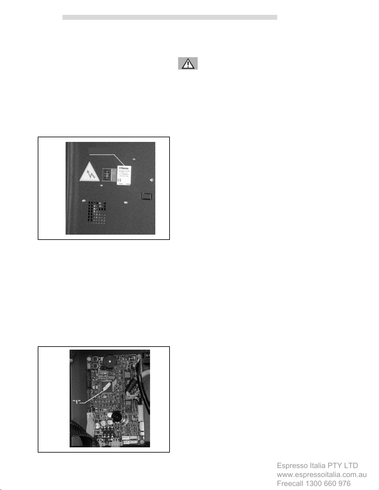
- the data registered on the Data plate located
on the rear part of the v. m. (fig. 1)
Data plate
fig. 1
- the board code appearing on the welding side
of the C.P.U. board.
Warning
It is absolutely forbidden to tamper with or modify
the data plate.
The SAECO International Group declines all
responsibility for injury caused to people or
damage caused to things as a consequence of:
- incorrect installation
- inappropriate electrical and/or water
connection
- inadequate cleaning and maintenance
- unauthorized modification
- improper use of the vending machine
- non-original spare parts
• In no event will the SAECO International
Group be obliged to indemnify any damage
caused as a result of the forced inactivity of
the machine due to failure.
• Installation and maintenance operations shall
be exclusively be performed by qualified
technicians.
- the version of program resident in the
microprocessor - see the adhesive label on
the component mounted on the C.P.U. board
ref. '1', fig. 2 or, if possible, the version of
program shown on the machine display when
button 2 is pressed on the CPU board to
activate the 'Service' mode (fig. 41).
• Use only specific foodstuffs for use in
automatic vending machines.
• The automatic vending machine is not
suitable for outside installation. The machine
shall be installed in dry places, with
temperatures not lower than 1°C and it shall
not be installed in places where cleaning is
done with water hoses (e.g. large kitchens..).
• If at the time of installation, the usage
conditions are different from those
established or are subject to change over
time, please contact the manufacturer
immediately before using the machine.
Furthermore, always act in compliance with
national or local standards.
fig. 2
6
1.4 Operator requirements
Espresso Italia PTY LTD
www.espressoitalia.com.au
Freecall 1300 660 976
To guarantee the safety of the machine three
operators with different skills are required:
User
Access to the inside of the machine is forbidden
to the user.
Supply operator
The safekeeping of the access key to the inside
of the machine is entrusted to the Supply
operator by the Maintenance Technician. He has
the task of supplying the products, external
cleaning, activating and stopping the machine.
English
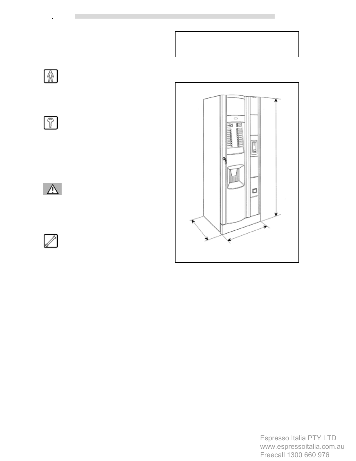
2 - TECHNICAL
SPECIFICATIONS
Weight from 146 to 155 Kg
Overall dimensions See fig. 3
mm. 1835
Warning
The Supply Operator is not authorized to carry
out operations that are indicated as competency
of the Maintenance technician in this publication.
Maintenance technician
The only person authorized to intervene and start
the programming procedures, adjust, set up and
upkeep the machine.
mm. 790
mm. 661
fig. 3
Power consumption See Data plate (fig.1)
Power supply voltage See Data plate (fig.1)
Electric voltage
frequency See Data plate (fig.1)
Power cord length 1,600 mm
Water mains connection 3/8 gas
Water mains pressure from 1.5 to 8 bars
(fig.4)
7

English
Espresso Italia PTY LTD
www.espressoitalia.com.au
Freecall 1300 660 976
fig. 4
Data plate showing the minimum
and maximum water pressure
3 - SAFETY
STANDARDS
3.1 Foreword
In compliance with the Machine Directive 98/37/
EEC, Low Tension Directive 73/23/EEC and CE
Marking Directive 93/68/EEC, the SAECO
International Group has drawn up a technical file
on D.A. SG700NE vending machine at its plants,
acknowledging during the design phase the rules
indicated in the Declaration of Conformity
included in the vending machine documentation.
CUP DISPENSER
Suitable for cups with 70-71 mm dia.
BOILER HEATING ELEMENTS
Armoured type:
from 1000 Watts for coffee boiler
from 1300 Watts for instant product boiler
CONTAINER CAPACITY
Coffee beans Kg 4,0
Instant coffee Kg 1,0
Granular milk Kg 2,1
Chocolate Kg 4,3
Tea Kg 5,9
Soup Kg 5,5
Sugar Kg 5,6
Cups 700
Stirrers 540
3.2 General safety rules
Warning
- Before using the vending machine, read this
manual carefully.
- Installation and maintenance operations shall
exclusively be performed by qualified
technicians.
- For no reason whatsoever shall the operator
access those parts of the machine that are
protected by guards requiring special
instruments for their removal.
- Good knowledge and absolute respect, from
a technical point of view, of the safety
standards and danger warnings contained in
this manual, are fundamental for installing,
using, servicing and maintaining the machine
in conditions of minimum risk.
8
Always disconnect the POWER CABLE before
maintenance or cleaning activities.
Do not, under no circumstances, intervene on
the machine or remove safety guards before hot
parts have cooled!
English
Espresso Italia PTY LTD
www.espressoitalia.com.au
Freecall 1300 660 976
- Operating reliability and the efficiency of the
machine performance are guaranteed only if
original spare parts are used.
- The automatic vending machine is not
suitable for outside installation. The machine
shall be installed in dry places, with
temperatures not lower than 1°C and it shall
not be installed in places where cleaning is
done with water hoses (e.g. large kitchens..).
- In order to guarantee the performance of the
machine, always keep the automatic vending
machine in perfect cleaning conditions.
- The SAECO International Group declines all
responsibility for injury caused to people or
damage caused to things as a consequence
of :
• incorrect installation
• inappropriate electrical and/or water
connection
• inadequate cleaning and maintenance
• unauthorized modification
• improper use of the vending machine
• non-original spare parts
4 - HANDLING AND
STORAGE
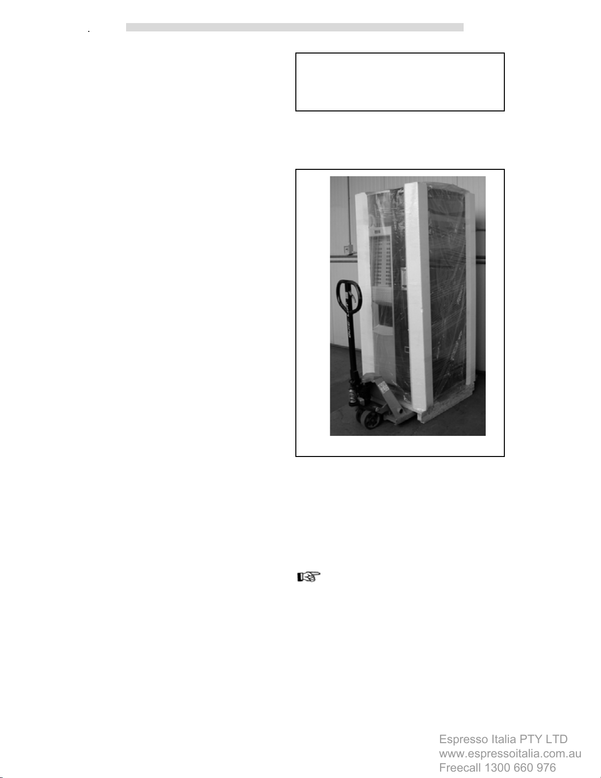
4.1 Handling and transport
Furthermore, always act in compliance with
national or local standards.
fig. 5
(fig.5)
The transport of the vending machine shall be
carried out by skilled personnel.
The vending machine is delivered on a pallet;
for handling purposes use a fork lift truck and
move it slowly in order to avoid any possible
overturning or dangerous oscillations.
Important
Avoid:
- lifting the vending machine with ropes or
presses
- dragging the vending machine
- turning over or laying the vending machine
down during transport
- jolting the vending machine
9
English
Espresso Italia PTY LTD
www.espressoitalia.com.au
Freecall 1300 660 976
With regard to the vending machine, avoid :
- bumping it
- overloading it with other packages
- exposing it to rain, cold weather or heat
sources
- keeping it in damp places
4.2 Storage
In the event of storage, avoid any overlapping of
several machines, keep them in a vertical
position, in dry places with temperatures not
lower than 1°C.
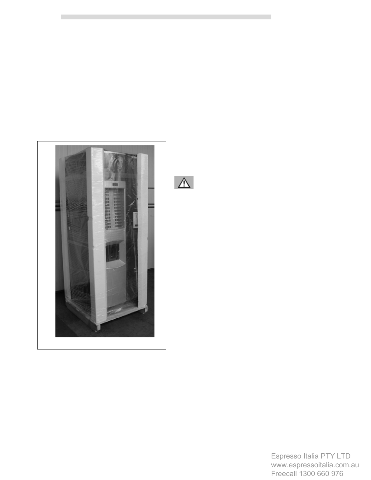
4.3 Packaging
The vending machine is protected by polystyrene
angles and by a transparent polypropylene film
(fig.6).
The automatic vending machine will be delivered
packaged, assuring both a mechanical guard
and protection against damage from any
environmental agents.
Labels are applied on the packaging, indicating:
- handle with care
- do not turn upside-down
- protect from rain
- do not overlap
- protect from heat sources
- not shock resistant
- type of vending machine and serial number
Important
When the transport is over, the packaging shall
be undamaged, which means it shall not:
fig. 6
- show any dent, sign of shocks, distortions or
breakages to the external packaging
- show wet parts or signs that could lead to
suppose that the packaging has been
exposed to rain, freezing weather or heat
- show signs of tampering
10

5 -GENERAL TECHNICAL
Espresso Italia PTY LTD
www.espressoitalia.com.au
Freecall 1300 660 976
DESCRIPTION
5.1 Permitted use
English
5.3 Basic operating concepts
During normal functioning, the vending machine
is in standby. By introducing the necessary
amount, according to the preset price, and
pressing the key relating to the desired beverage,
a beverage dispensing cycle is activated. It can
be divided in different processes:
The vending machine is to be used exclusively
for the dispensing of beverages, prepared by
mixing foodstuffs with water (by brewing for
coffee).
For this purpose, use products that the
manufacturer has declared suitable for the
automatic distribution in open containers.
Beverages are brewed in appropriate plastic cups
automatically dispensed by the machine. The
sugar stirrer is automatically dispensed.
The beverages shall be drunk immediately and
under no circumstances shall they be kept for
subsequent consumption.
5.2 Models
The following terminology is used so as to
distinguish the various models of automatic
vending machines:
SAECO GROUP 700N E PLUS :
version with plastic brew group and 5 instant
products, equipped with two boilers and 64 mm
grinders.
CUP DISPENSING
• This is the first operation that the vending
machine activates - except for 'without cup'
dispensing selection.
• The motor inside the cup dispenser moves
the scrolls in order to separate and let the
cup fall into the special support fork inside
the dispensing outlet.
SAECO GROUP 700N M PLUS :
version with plastic brew group and 5 instant
products, equipped with one boiler and 64 mm
grinders.
SAECO GROUP 700N E :
version with plastic brew group and 5 instant
products, equipped with two boilers and 48 mm
grinders.
SAECO GROUP 700N M :
version with plastic brew group and 5 instant
products, equipped with one boiler and 48 mm
grinders.
Warning
This manual refers to the top-of-the-range model:
it is therefore possible to find descriptions or
explanations not relating to the machine you
have.
11

English
Espresso Italia PTY LTD
www.espressoitalia.com.au
Freecall 1300 660 976
SUGAR AND STIRRER DISPENSING
Where provided for and required, a preset
maximum dose of sugar is dispensed, with the
possibility to stop the machine when the required
dose has been reached.
Dispensing is divided in the following phases:
• the gearmotor activates the sugar container
screw, dispensing the desired quantity of
product into the conveyor tube.
• the dragging motor of the channel is engaged
and conveys the sugar into the cup.
• the solenoid is activated, and the stirrer is
directly dispensed into the cup through a
special channel (fig.9).
INSTANT BEVERAGES
This process takes place only after the
dispensing of the cup, the sugar and the stirrer.
According to the beverage selected and the
model of the vending machine - single or double
boiler - the following processes are enabled for
the beverage brewing.
• If fitted, the motor mixer is engaged.
• In case of machines with espresso coffee
single boiler the solenoid valve for instant
products (ref. '1' fig.7) is installed on the coffee
boiler and when engaged it conveys the
programmed quantity of water into the mixer.
Then, the pump (ref. '2' fig. 7) is engaged and,
controlled by a special electronic device
(volumetric counter ref. '3' fig. 7), it dispenses
the programmed quantity of water.
fig. 7
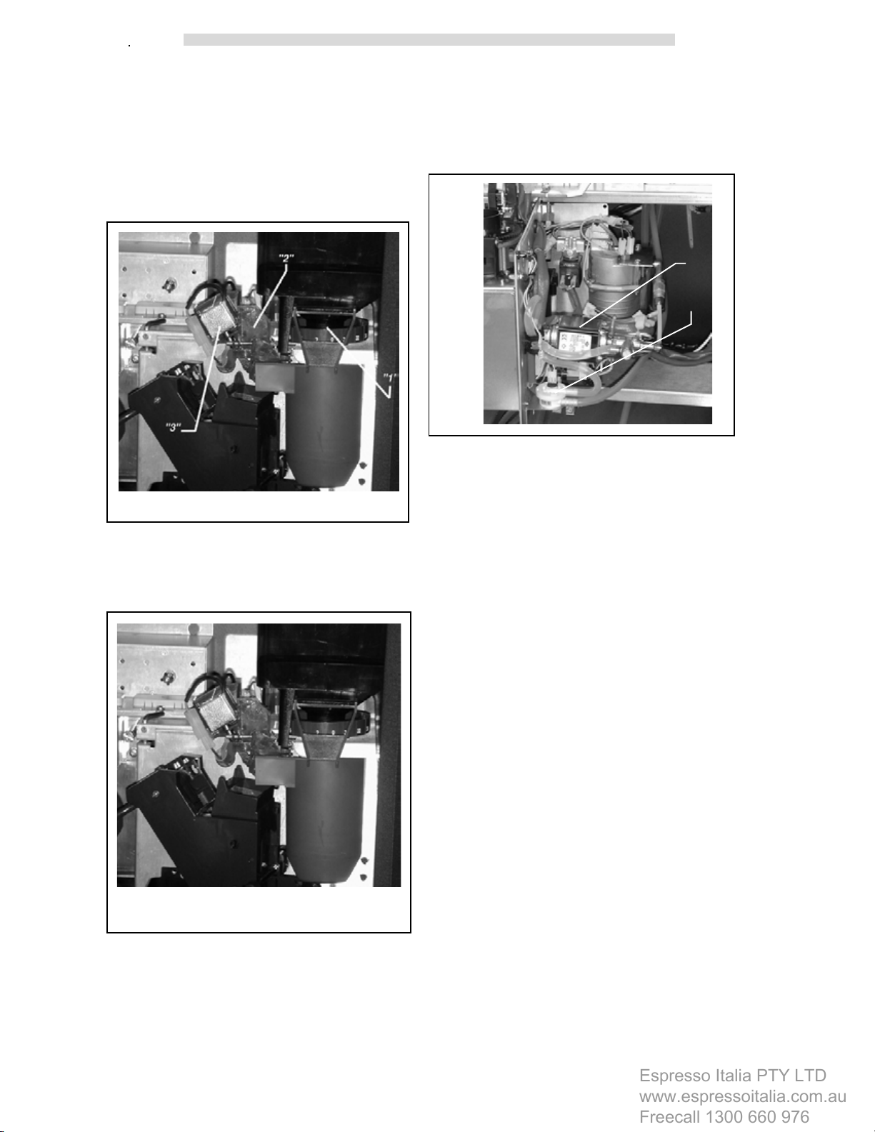
• In case of machines with a double boiler, the
solenoid valve for instant products (ref. '1' fig.
8), located on a non-pressurized boiler (ref.
'2' fig. 8), is engaged by means of a timer in
order to fill the cup with the programmed
quantity of water. In this case, the water
outflows by falling.
“2”
“1”
fig. 8
• The gearmotor of instant products actuates
the screw so that the latter dispenses the
preset quantity of product inside the mixer for some versions several products can be
dispensed in the same mixer -).
“1”
12
• Once the preset quantity of water and powder
is dispensed, the mixer is disconnected.
English
Espresso Italia PTY LTD
www.espressoitalia.com.au
Freecall 1300 660 976
ESPRESSO COFFEE
This process takes place only after the
dispensing of the cup, the sugar and the stirrer.
• the grinder (ref. '1' fig.9) is engaged and runs
until the ground coffee dose set by the dosing
unit (ref '2' fig.9) is reached.
fig.9
• the electromagnet of the dosing unit (ref. '3'
fig.9) controls the door opening and the
subsequent falling of the coffee into the
brewing cup.
• controlled by the appropriate electronic device
(volumetric counter ref. '2' fig.11), the pump
dispenses the preset quantity of water sucked
from the coffee boiler (ref. ‘1’ fig.11).
“1”
“2”
fig.11
• the brew group gearmotor goes back to its
rest position while the used coffee tablet is
ejected.
According to the type of program set (see
programming menu), the above procedure for
the grinder and dosing unit engagement can take
place in reverse.
fig.10
• the group rotation gearmotor moves the group
onto the brewing position and compresses
the coffee tablet (fig.10).
13

English
Espresso Italia PTY LTD
www.espressoitalia.com.au
Freecall 1300 660 976
6 - INSTALLATION
6.1 Positioning
The vending machine is not suitable for outside
installation. It shall be installed in dry places, with
temperatures not lower than 1°C. Furthermore
it shall not be installed in places where cleaning
is done with water hoses or where there is the
danger of explosions or fires.
- If positioned near a wall, there shall be a
minimum distance of at least 5 cm from the
wall (fig. 12), so as to allow regular ventilation.
Under no circumstances cover the vending
machine with cloths or similar.
fig.12
14
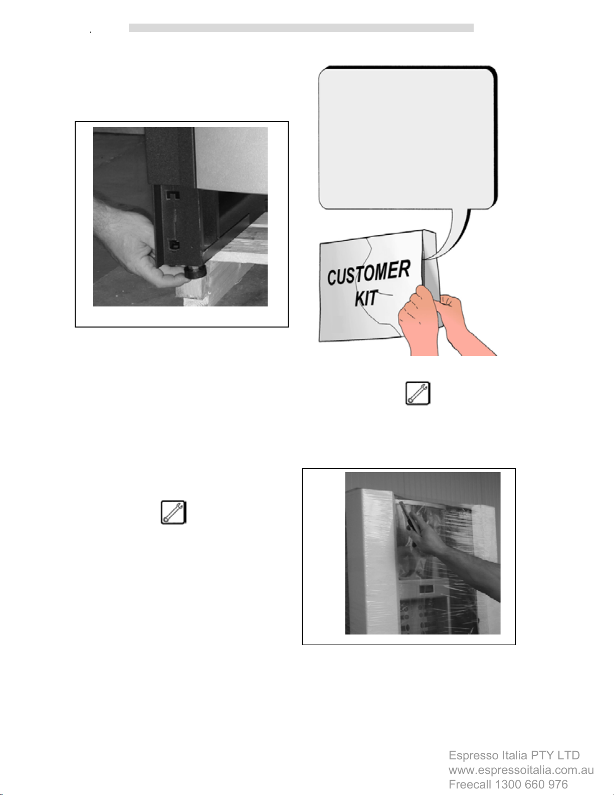
- Position the vending machine, checking the
Espresso Italia PTY LTD
www.espressoitalia.com.au
Freecall 1300 660 976
levelling by means of the adjustable feet
already assembled on the machine (fig. 13).
Make sure that the vending machine does
not have an inclination exceeding 2 degrees.
fig.13
English
- Instruction booklet.
- Powder tank plates and prices in
euro.
- Pushbutton panel selection
labels.
- Instruction labels.
- Wiring and hydraulic diagram.
- Power cord.
- Safety micro key
(Maintenance technician).
- Declaration of conformity.
The SAECO International Group declines all
responsibility for inconveniences due to the
failure in observing the above mentioned
installation rules.
If installation takes place in safety evacuation
corridors, make sure that the machine with the
door open assures sufficient space for people
to pass by (fig. 11).
In order to avoid the floor to get dirty as a result
of accidental spillage of products, use, if
necessary, a sufficiently wide protecting device
to cover the operating area under the vending
machine.
6.2 Receipt
Upon receipt of the automatic vending machine,
it is necessary to check it has not suffered
damage during transport. If damage of any kind
is noticed, immediately place a claim with the
forwarder.
An envelope is supplied with the vending
machine, called 'CUSTOMER KIT', containing
the objects shown in Fig. 14.
fig.14
6.3 Unpacking
- Free the vending machine from the packaging,
cutting the protective film in which it is
wrapped, along one of the protection angles
(fig.15).
fig.15
15

English
Espresso Italia PTY LTD
www.espressoitalia.com.au
Freecall 1300 660 976
- Remove the vending machine from the pallet,
unscrewing the screws that secure it to the
pallet (fig.16).
fig.16
- Remove the key from the beverage
dispensing outlet (fig.17).
- Remove the polystyrene blocking the product
containers (fig.18)
fig.18
Warning:
The packing material shall not be accessible to
unauthorized people, as it is a potential source
of danger. For the disposal please contact
qualified companies.
fig.17
Open the door of the vending machine and
remove the adhesive tape from the components.
16
6.4 Water mains connection
Espresso Italia PTY LTD
www.espressoitalia.com.au
Freecall 1300 660 976
Before connecting the vending machine to the
water mains, make sure the water :
- is drinking - if possible by means of test
laboratory certification
English
- connect the tap to the vending machine, using
a copper or nylon pipe, suitable for foodstuffs
and for the purpose of bearing the water
supply pressure. Should a flexible hose be
used, it is necessary to assemble the
reinforcement bearing inside, supplied with
the machine.
- has a pressure ranging between 1.5 bars
and 8 bars, otherwise use a pump or a water
pressure reducer accordingly
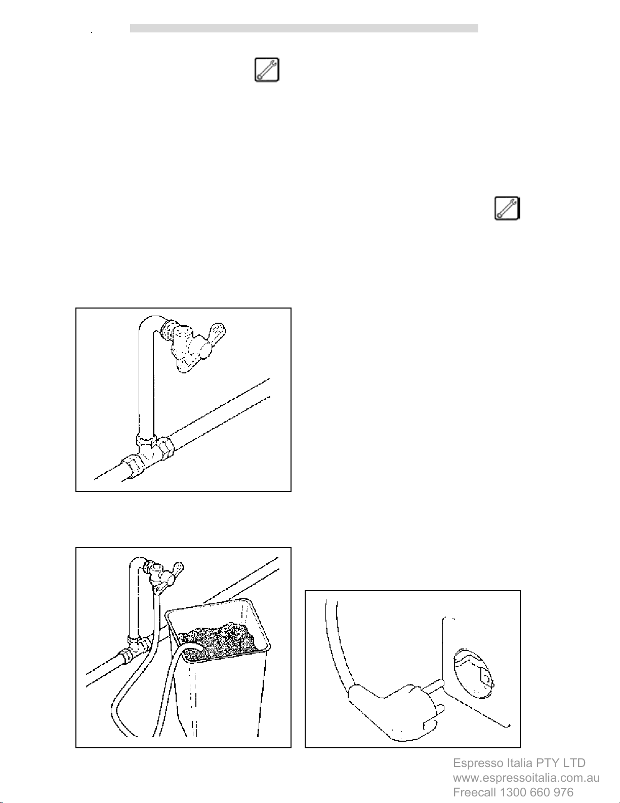
- if not already fitted, install a tap in an
accessible position, so as to separate the
equipment from the water mains, should it
be necessary (fig. 19).
fig.19
- the connection provided for is a 3/8 gas-type
fitting.
6.5 Electric Mains connection
The vending machine is designed to operate with
single phase voltage at 230 Volts and is protected
by 8A rapid fuses.
We suggest checking the following:
- lthe mains voltage of 230 V shall not exceed
a ± 6% fluctuation
- the power supply must be suitable to the
machine
- a diversified protection system shall be
connected
The machine shall be earthed in observance with
operating safety rules in force.
For this reason, verify the system earth wire
connection to ascertain that it is efficient and in
compliance with national and European electric
safety standards.
- let some water flow out of the tap so that to
eliminate possible traces of impurities and dirt
(fig.20).
fig.20
If necessary, have the system inspected by
qualified personnel
- The vending machine is provided with a power
cord (fig.21)
fig.21
17
 Loading...