

Page 1
Vending machine
Espresso Italia PTY LTD
www.espressoitalia.com.au
Freecall 1300 660 976
ACCESSORIES AND PAYMENT SYSTEMS
D.A. COMBISNACK
Type: D.A. COMBISNACK
USE AND MAINTENANCE
Page 2
English
Espresso Italia PTY LTD
www.espressoitalia.com.au
Freecall 1300 660 976
Contents
1 - DIAGRAM OF CONNECTIONS TO THE KEYPAD BOARD/CPU:. ................................................. 3
2 - PAYMENT SYSTEM INSTALLATION. ............................................................................................. 4
3 - PAYMENT SYSTEM FEEDER KIT. ................................................................................................... 5
4 - INDEPENDENT TANK KIT. ............................................................................................................ 7
5 - FLOAT KIT. .................................................................................................................................. 10
6 - PULSE COUNTER KIT. ................................................................................................................. 12
7 - WATER SOLENOID VALVE KIT. ................................................................................................... 13
8 - SUGAR COIL KIT. ....................................................................................................................... 15
9 - SAECO CARD ASSEMBLY KIT. .................................................................................................. 17
9.1 - Saeco card programming.....................................................................................................19
10 - HANDLING KIT. .......................................................................................................................... 20
11 - BRITA PURIFIER KIT. ................................................................................................................... 21
12 - RS 232 INTERFACE BOX............................................................................................................ 23
13 - SAECO WATER SOFTENER SUPPORT. ........................................................................................ 24
14 - PROGRAMMING KEY. ............................................................................................................... 25
15 - 12V PARALLEL COINER KIT. ...................................................................................................... 25
16 - CLOCK MODULE INSERTION (TIME KEEPER)........................................................................... 26
16.1 - TIME KEEPER functions in the programming menus ..................................................................... 26
16.2 - TIME KEEPER functions in the maintenance menus ...................................................................... 27
2
Page 3
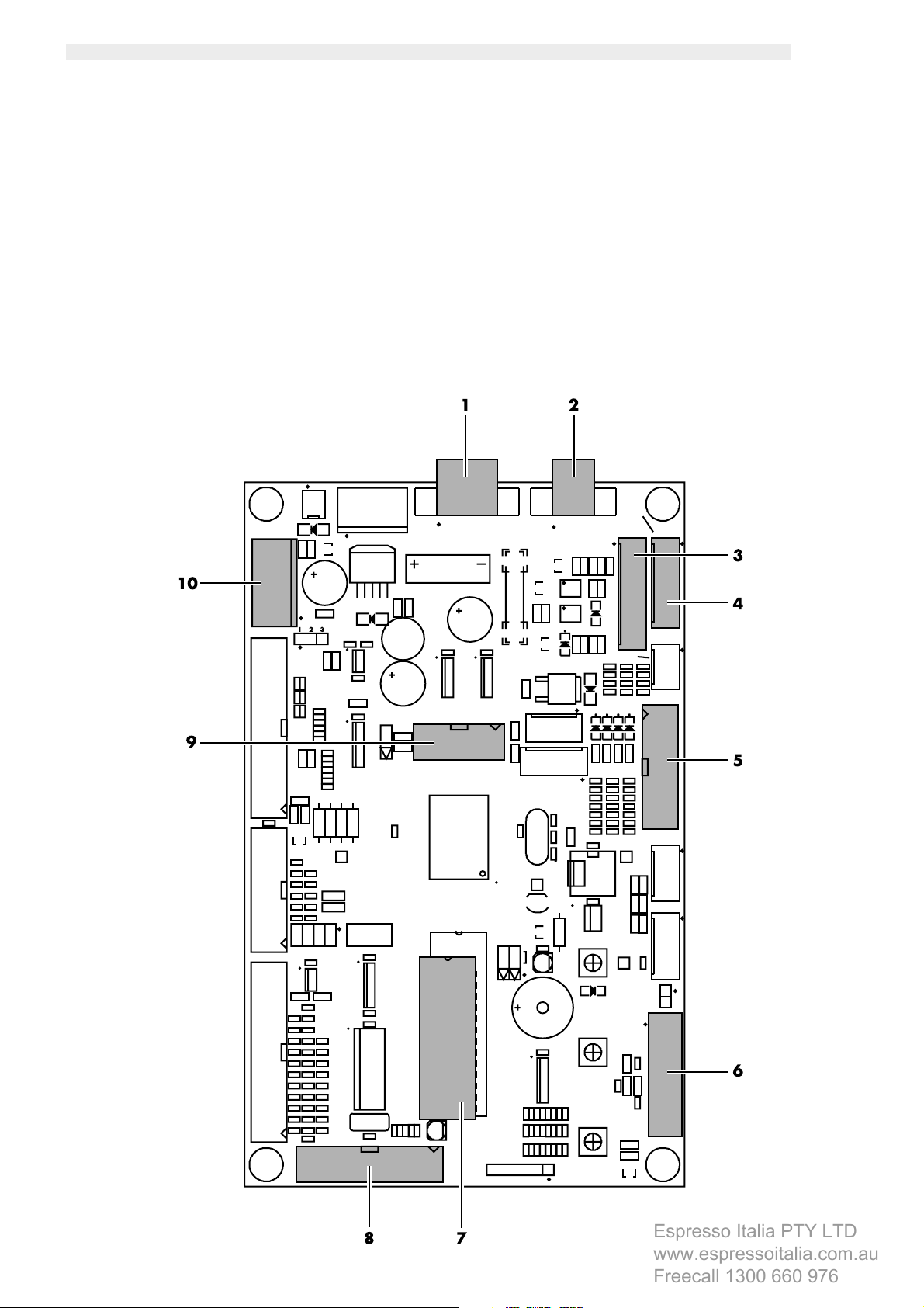
1 - DIAGRAM OF CONNECTIONS TO THE KEYPAD BOARD/CPU:
Espresso Italia PTY LTD
www.espressoitalia.com.au
Freecall 1300 660 976
1. MDB systems;
2. BDV, MDB and executive system power supply;
3. 24 V DC / 12 V DC banknote reader;
4. Executive and BDV systems;
5. 24 V DC parallel coiner (non-change giving);
5. 12 V DC parallel coiner (non-change giving) with its suitable kit,
6. Programming key;
7. Clock module;
8. Saeco card;
9. Connector for PC serial interface
10. Feeder kit for payment systems;
English
fig. 1
3
Page 4
English
Espresso Italia PTY LTD
www.espressoitalia.com.au
Freecall 1300 660 976
Maintenance technician
It is used to indicate operations to be performed by specialized maintenance technicians only.
He is the only person authorized to keep the KEY TO ACTIVATE THE SAFETY MICROSWITCH which allows disabling the security
system.
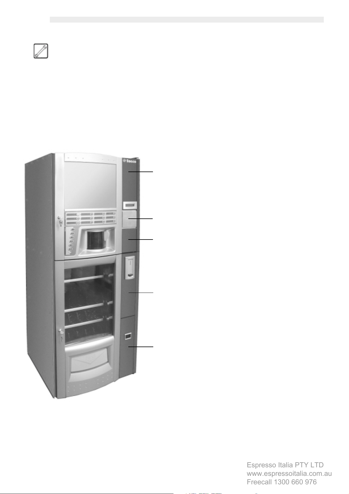
2 - PAYMENT SYSTEM
INSTALLATION
A
B
C
D
This vending machine is supplied with panels assembled as shown
in fig. 2. It is possible to change and replace them with those
provided by Saeco according to the customer’s requirements.
- Panel for OTR. and M.IVO banknote readers
- Panel for JCM banknote reader
- Panel for SMILE banknote reader
- Panel for m125 COINCO banknote reader
- Panel for NRI G13 coiner
- Lower Neutra panels (to combine with NRI G 13 panel)
Saeco also supplies the relevant wiring harnesses to connect the
different payment systems.
A specific kit must be used to connect the 12V non-change-giving
parallel coiner.
Open the front doors to replace the panels and remove the CPU
guard to replace the upper door.
Before taking panel B off, it is necessary to remove also the
instruction support steel sheet.
Panel for
OTR. and M.IVO banknote readers
It is inserted in lieu of panels B, C and is preset for OTR. and
M.IVO banknote readers.
- Connect the payment system cable to the suitable connector on the CPU card according to the instructions supplied by the diagram at
page 3.
- If during the payment system installation, the “B” panel instructions are removed, it will be necessary to insert the proper instructions, in
a large, short format, in the “advertising image” area.
4
fig. 2
Panel for JCM banknote reader
It is inserted in lieu of panels B, C and is preset for JCM banknote
reader.
E
Panel for SMILE banknote reader
It is inserted in lieu of panels B, C and is preset for SMILE banknote
reader.
Panel for m125 COINCO banknote reader
It is inserted in lieu of panels B, C and is preset for m125 COINCO
banknote reader.
Panel for NRI G13 coiner and Neutra lower panel
These two panels must be combined.
They are inserted in lieu of panels D, E and are preset for NRI
G13 COINER.
Page 5
English
Espresso Italia PTY LTD
www.espressoitalia.com.au
Freecall 1300 660 976
3 - PAYMENT SYSTEM
FEEDER KIT
This kit provides all the necessary power supply for the proper
operation of the payment systems connected to the CPU card of
Combisnack vending machine, which have a mains voltage of
+ 12 Vdc (parallel banknote readers) or + 6 Vdc (1432.0xx
and 1471.0xx models saeco card).
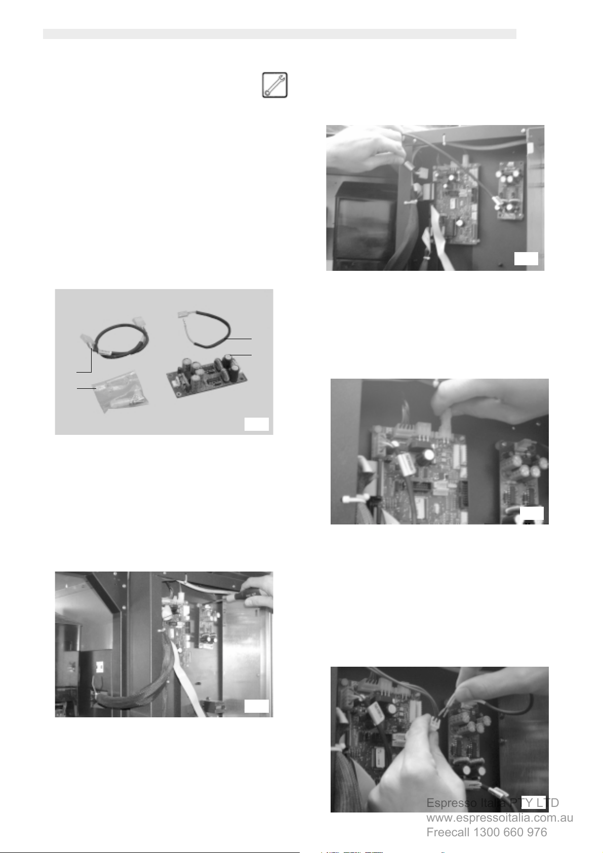
Assembly kit (fig. 3)
a. 1 feeder outlet wiring harness - CPU card
b. 4 screws and spacers
c. 1 feeder inlet wiring harness - CPU card
d. 1 +6Vdc / +12Vdc feeder board
c
d
a
b
- Connect the wiring harness (ref. a, fig. 3) to the payment
system power supply board as well as to the CPU card (fig.
5). See instructions on harness to carry out the connection.
fig. 5
- Unplug the four-pin connector from the CPU card (fig. 6).
fig. 3
Installation
- Open the upper door and fasten (fig. 4) the payment system
power supply board (ref. d, fig. 3) to the same door by using
the four screws and spacers (ref. b, fig. 3).
fig. 4
fig. 6
- Connect the two-pin connector (ref. c, fig. 3) to the payment
system power supply board. Connect the 2 contacts of the
other end to the 2 free slots of the 4-pin connector that was
previously unplugged from the CPU card (fig. 7).
fig. 7
5
Page 6

English
Espresso Italia PTY LTD
www.espressoitalia.com.au
Freecall 1300 660 976
- Connect the four-pin connector to the CPU card (fig. 8).
fig. 8
- Close the vending machine upper door.
The mains voltage values provided by this feeder can also be
found on CN6 (ref. 3, fig. 1) and CN9 (ref. 8, fig. 1) connectors
of CPU card.
Connector Description Voltage Pin
CN6 connector for parallel banknote readers +12Vdc 7
CN9 connector for saeco card universal module +5Vdc or +6Vdc 12,13,14
(see table below)
Pin 12, 13, 14 voltage of CN6 is set according to JP8 jumper
position.
JP8 jumper position Voltage on CN6 12, 13, 14 pins
1-2 +6Vdc
2-3 +5Vdc
JP8 jumper
position
6
Page 7
English
Espresso Italia PTY LTD
www.espressoitalia.com.au
Freecall 1300 660 976
4 - INDEPENDENT TANK KIT
This kit allows the vending machine to be supplied by means of
an internal tank instead of by the water network. To do this, it is
necessary to use the tank inside the machine as drinking water
hopper. If the machine has not been started for the first time, and
the tank has already been used as discharge fluid tank, it shall be
replaced with a new one.
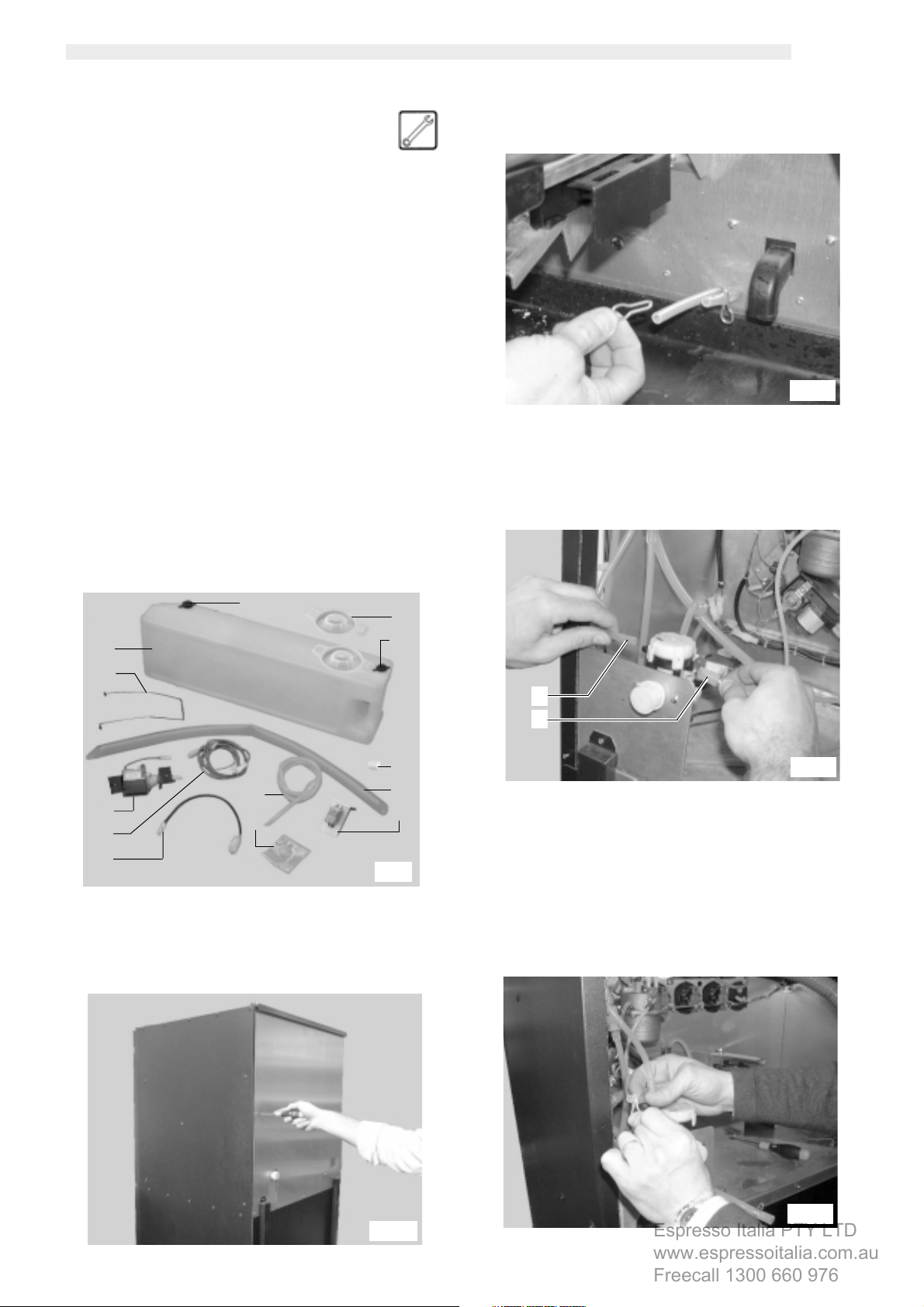
Assembly kit (fig. 9)
a. 1 discharge fluid tank with cap
b. 1 spring for tank
c. 1 pump with supports and pipe fitting
d. 1 pump wiring harness
e. 1 pump feeding wiring
f. 1 cap for spout
g. 1 water inlet pipe
h. 4 screws and washers (two of them measure 4,3x12 and the
other two 4,3x16)
i. 1 perforated cap
m. 1 cap for spout
n. 1 KAPSTO GPN 350 dia 30 cap
p. 1 PVC drain tube
r. 1 relay with support plate
- Open the upper door and take out the retaining spring from
the left hand pipe (fig. 11).
fig. 11
- Disconnect the two pipes from the water inlet solenoid valve
(fig. 12)
f
a
i
m
b
n
c
h
g
p
r
d
e
fig. 9
Installation
- Remove the machine rear panel (fig. 10) by untightening the
screws and disconnecting the ground wiring placed on the
machine.
s
t
fig. 12
- Apply the pipe retaining spring (see fig. 11) on the silicone
pipe (ref. t, fig. 12) fitted on “T” and previously removed from
the inlet solenoid valve (fig. 13).
fig. 13
fig. 10
7
Page 8
English
Espresso Italia PTY LTD
www.espressoitalia.com.au
Freecall 1300 660 976
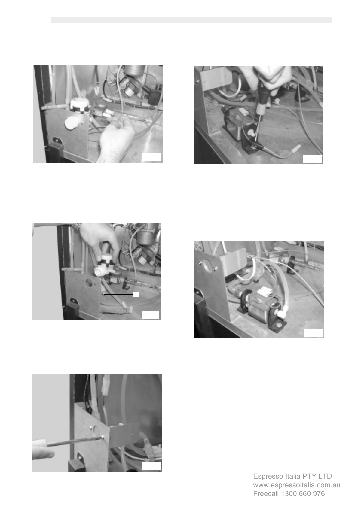
- Disconnect the two power supply wirings from the water inlet
solenoid valve (fig. 14).
fig. 14
- Remove the water inlet solenoid valve (fig. 15).
- Tighten the pump by means of the two screws and two washers
4,3x16 (ref. h, fig. 9) to the bottom (fig. 17).
fig. 17
- Connect the pipe (ref. s, fig. 12), previously extracted from
the water inlet solenoid valve, to the fitting located on the
pump (fig. 18).
- Withdraw the cap (ref. u, fig. 15). Connect the water inlet
pipe to the pump. Move the other end of the pipe to the
lower part of the vending machine passing through the hole
(ref. u, fig. 15)
u
fig. 15
- Tighten the relay and support plate (ref. r, fig. 9) by using the
screws previously taken from the inlet solenoid valve (fig. 16)
fig. 16
fig. 18
- Carry out all the electric connections as indicated by the
diagram below.
8
Page 9
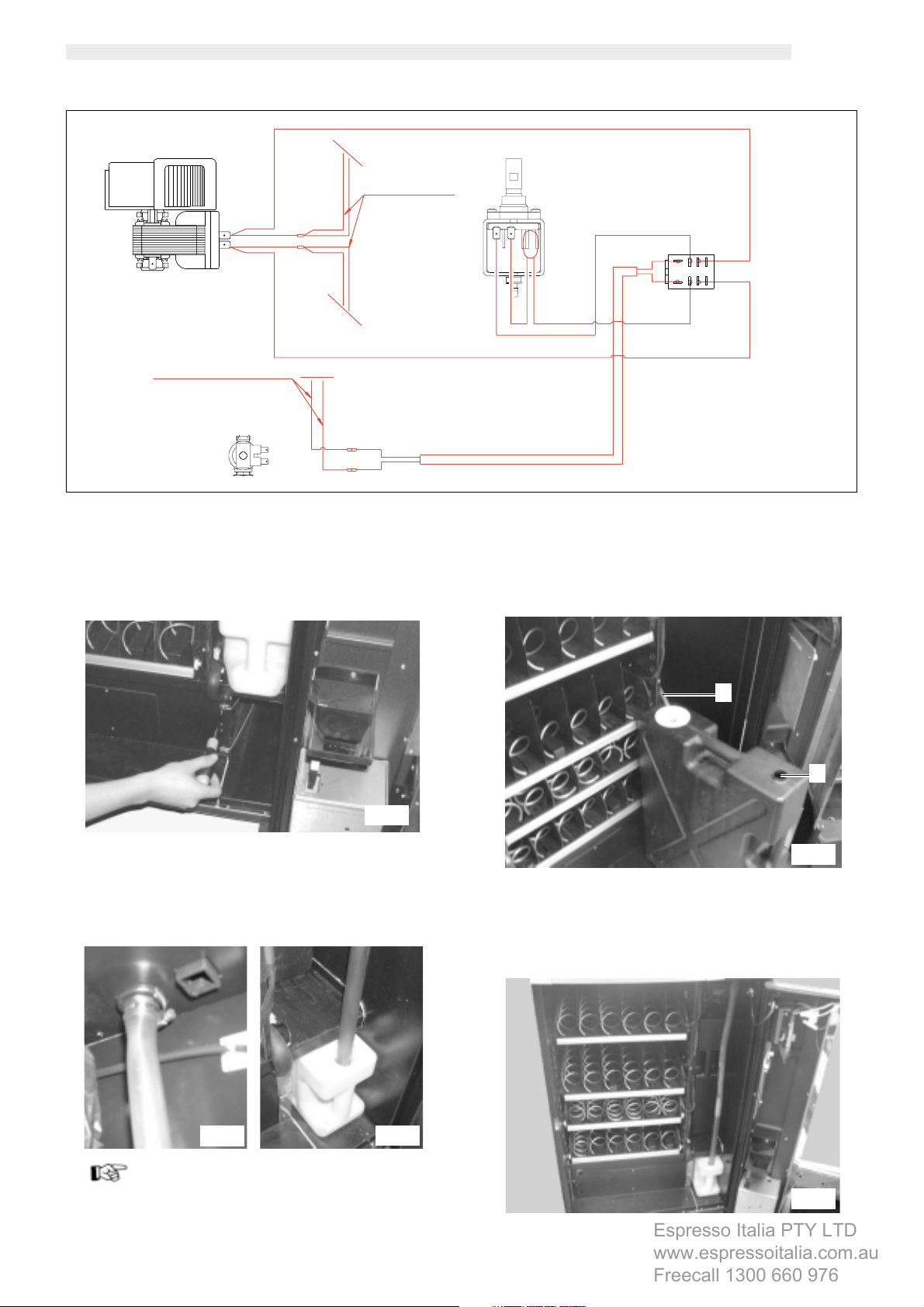
230V 50Hz
Espresso Italia PTY LTD
www.espressoitalia.com.au
Freecall 1300 660 976
FAN
Power supply wirings inlet solenoid valve
INLET SOLENOID VALVE
PINK
DARK BLUE
PINK
DARK BLUE
PINK
DARK BLUE
DARK BLUE
Power supply wirings
BLUE
PINK
fan motor
PUMP 1
DARK BLUE
BLUE
RED
English
RELAY
PINK
DARK BLUE
RED
24 V D.C.
RED
- Reassemble the machine rear panel taking care to reconnect
the earth cable.
- Open the V.M. lower door.
-
Tighten the spring (ref. b, fig. 9) in the position shown in fig. 29
by using the two screws and two washers 4,3x12 (ref. h, fig. 9).
fig. 20
- Replace the pipe fastened to the drain channel (fig. 21) with
the drain tube (ref. p, fig.9). Remove the cap (ref. m, fig. 9)
from the tank. Insert the other end of the pipe in the discharge
fluid tank (fig. 22). Make sure that the other tank holes are
properly capped.
fig. 19
- Insert the pipe (ref. g, fig. 23) in the perforated cap of the
drinking water tank.
- Fill the drinking water tank.
g
v
fig. 23
- Fit the cap on the tank. Place the tank inside the V.M. (fig. 24)
by sliding the pipe inside the tank itself. Close the hole (ref. v,
fig. 23) by means of the cap (ref. n, fig. 9).
fig. 21
Important
Before removing the tank to empty it, close the pipe hole
using the relevant cap (ref. m, fig. 9). This will help preventing
any liquid spillage due to the surge effect.
fig. 22
fig. 24
- Close the vending machine lower door.
9
Page 10

English
Espresso Italia PTY LTD
www.espressoitalia.com.au
Freecall 1300 660 976
5 - FLOAT KIT
It allows the display to read the discharge fluid maximum level. In
this condition, no hot beverage is available and the display will
read “ERROR 09”.
The float can be installed in different positions according to whether
the machine is connected to a water network (22 L tank) or uses
an independent tank (7L tank).
Assembly kit (fig. 25)
a. 1 basket set for discharge fluid level
b. 2 screws
c. 1 reed wiring
a
b
c
- Slide the other end of the reed
wiring inside the hole (ref. d,
fig. 26) and couple it to the
connector (ref. f, fig. 27).
- Remove the tank cap (fig. 28) and replace it with the discharge
level basket set (fig. 29).
f
fig. 27
g
fig. 28
fig. 29
fig. 25
Important
When assembling the lower level sensor (fig. 26) disconnect
the higher sensor (fig. 30). The drain level control system
doesn’t work if two sensors are connected.
Installation
- Open the front lower door.
- If it is applied on the independent tank version, it is necessary
to remove the 7 L tank (ref. g, fig. 28) and to assemble the
reed wiring (ref. c, fig. 25) by means of the two screws (ref.
b, fig. 25) according to the position shown in the figure (ref.
e, fig. 26).
d
e
- Reinstall the tank.
- If it is applied to the water network version, it is necessary to
remove the 22L tank (ref. i, fig. 31) and to fit the reed wiring
(ref. c, fig. 25) by means of the two screws (ref. b, fig. 25)
on the square (ref. h, fig. 30). Then, couple the other end to
the connector (fig. 30).
h
fig. 30
- Remove the tank cap (fig. 31) and replace it with the discharge
level basket set (fig. 32).
10
fig. 26
i
- Reinstall the tank.
fig. 31
fig. 32
Page 11

English
Espresso Italia PTY LTD
www.espressoitalia.com.au
Freecall 1300 660 976
Access the machine programming menu and set “YES” in the
“TANK” menu (fig. 34) to enable the display reading of the
discharge fluid maximum level.
In order to properly carry out this operation, disable the safety
device and press key 1 (fig. 33) to access the programming
menu.
If no password has been assigned you enter the programming
menu directly.
Important
If vending machine was assigned a password to enable the
programming menu, “PASSWORD 0000” will appear on
display with a flashing cursor on the first digit.
Now digit the password using UP and DOWN keys. Confirm
the entered digit by means of ENTER key.
To exit the programming menu and return to the normal operation
of the vending machine:
- press key 1 again;
- remove the key from the safety switch to turn off the vending
machine;
- close the door and wait for the self-configuration process to
end.
Important
When the tank maximum level is reached, the display will
read “HOT BEVERAGES NOT AVAILABLE” (ERROR 09 code).
In this condition, the V.M. cannot brew hot beverages. It is
therefore necessary to empty the tank. After emptying the
tank, the error message will automatically disappear at the
machine switching on.
SISTEM MANAGEMENT
VM CODE
0000
STOP
MIN. TEMPERATURE
098
MAX. TEMPERATURE
108
COLD TEMPERATURE
6
1
fig. 33
Entries selectable
only with complete
menus
COMPRESSOR
YES
DRAINAGE TANK
NO
DRAINAGE TANK
>Y< N
fig. 34
11
Page 12

English
Espresso Italia PTY LTD
www.espressoitalia.com.au
Freecall 1300 660 976
6 - PULSE COUNTER KIT
The vending machine can be fitted with an electromechanical
pulse counter (24V DC) which will count the number of coffees or
the total beverages brewed by the machine.
Assembly kit (fig. 35)
a. 1 pulse counter with support
b. 2 screws
a
b
fig. 35
Installation
- Open the upper door and fasten the pulse counter (ref. a, fig.
35) to it (fig. 36) by means of the two screws (ref. b, fig. 35).
To enable the counting of coffees or beverages brewed, access
the machine programming menu and set “COFFEE” or
“BEVERAGES” in the “PULSE COUNTER” menu (fig. 38).
In order to properly carry out this operation, disable the safety
device and press key 1 (fig. 33) to access the programming
menu.
If no password has been assigned you enter the programming
menu directly.
Important
If vending machine was assigned a password to enable the
programming menu, “PASSWORD 0000” will appear on
display with a flashing cursor on the first digit.
Now digit the password using UP and DOWN keys. Confirm
the entered digit by means of ENTER key.
To exit the programming menu and return to the normal operation
of the vending machine:
- press key 1 again;
- remove the key from the safety switch to turn off the vending
machine;
- close the door and wait for the self-configuration process to
end.
fig. 36
- Couple the pulse counter wiring with the “CN14” connector
of the board (fig. 37).
fig. 37
SISTEM MANAGEMENT
VM CODE
0000
STOP
MIN. TEMPERATURE
098
MAX. TEMPERATURE
108
COLD TEMPERATURE
6
COMPRESSOR
YES
DRAINAGE TANK
NO
MECH. COUNTER
COFFEE
Entries selectable
only with complete
menus
MECH. COUNTER
COFFEE
MECH. COUNTER
BEVERAGES
12
fig. 38
Page 13

English
Espresso Italia PTY LTD
www.espressoitalia.com.au
Freecall 1300 660 976
7 - WATER SOLENOID
VALVE KIT
It is possible to brew hot water alone by installing the required kit
Assembly kit (fig. 39)
a. 1 water pipe set
b. 1 OR, pipe clamp and 1/8" H4,5 nut
c. 1 two-way solenoid valve
c
a
b
fig. 39
- Open the upper door and loosen the screw (fig. 42) fixing
the block support plate.
fig. 42
- Remove the hopper (Fig. 43).
Installation
- Remove the machine rear panel (fig. 40) by untightening the
screws and disconnecting the ground wiring placed on the
machine.
fig. 40
- Unscrew the cap inserted on the solenoid valve block (fig.
41) and hold the latter to avoid any excessive stress to the
block support plate.
fig. 43
- Loosen the two screws fixing the block support plate (fig. 44).
fig. 44
fig. 41
13
Page 14

English
Espresso Italia PTY LTD
www.espressoitalia.com.au
Freecall 1300 660 976
- Screw the nut and fix the OR (ref. b, fig. 39) on the 2-way
solenoid valve (ref. c, fig. 39). Remove the block support
from its seat and screw the solenoid valve in the hole (fig. 45)
previously cleared from its cap (fig. 41). The solenoid valve
must be placed with fastons upwards
Reinstall the block support in their seat and tighten the screws.
fig. 45
- Insert the pipe clamp (ref. b, fig. 39) on pipe (ref. a, fig. 39).
Then, fasten the pipe (fig. 48) at the solenoid valve outlet and
position the pipe retaining spring.
Slide the other end of the pipe inside the assembly plate
passage hole (ref. d, fig. 48).
- Reassemble the machine rear panel.
d
fig. 48
- Remove the clamp (fig. 46) that fastens the two unused cables.
fig. 46
- Connect the 2 free cables to the solenoid valve taking care to
insert the red cable on the left and the white cable on the
right.
- Fasten the pipe end with fitting to the spout (fig. 49).
fig. 49
To brew hot water alone, it is necessary to set the beverage
associated with the required key according to the following
parameters:
Parameter Value
Sequence 0001
Soluble product quantity 1 0
14
fig. 47
H2O soluble product quantity 1
% soluble 1 100
sugar 0
- Close the vending machine upper door.
Set the required water quantity
Page 15

English
Espresso Italia PTY LTD
www.espressoitalia.com.au
Freecall 1300 660 976
8 - SUGAR COIL KIT
This kit allows the sugar door opening only when required, since
an electromagnet controls it. This prevents any sugar grain from
accidentally falling when the “without sugar” option has been
selected.
Assembly kit (fig. 50)
a. 1 two-pin connector
b. 1 connecting rod
c. 2 M3x6 screws, 1 M3x8 screw and 1 M3 nut
d. 1 relay electromagnet
e. 1 spring
f. 1 sticker
c
d
- Disassemble the sugar-dispensing channel (Fig. 52).
fig. 52
- Install the connecting rod (ref. b, fig. 50) on the electromagnet
piston (ref. d, fig. 50) by means of the spring (ref. e, fig. 50)
to obtain the unit shown in fig. 53.
- Apply the sticker (ref. f, fig. 50) to the electromagnet (fig. 54)
in order to seal the hole located on the machine housing.
a
b
e
f
fig. 50
Installation
- Open the upper front door.
- Remove the sugar-dispensing channel by opening the screw
(ref. g, fig. 51).
g
fig. 53
- Assemble this unit (see fig. 54) on the sugar channel (fig. 55)
by means of two M3x6 screws (ref. c, fig. 50).
fig. 54
fig. 51
fig. 55
15
Page 16

English
Espresso Italia PTY LTD
www.espressoitalia.com.au
Freecall 1300 660 976
- Fasten the connecting rod on the sugar door (fig. 56) by
means of an M3x8 screw and an M3 nut (ref. c, fig. 50).
fig. 56
- Assemble the whole unit on the sugar stirrer dispenser (fig.
57)
- Reinstall the sugar channel and fix it with the spring (fig. 59).
fig. 59
- Close the vending machine upper door.
fig. 57
- Couple the connector (ref. a, fig. 50) with the electromagnet
by means of the fastons. Insert the other end in the connection
located on the mounting plate (fig. 58).
fig. 58
16
Page 17

English
Espresso Italia PTY LTD
www.espressoitalia.com.au
Freecall 1300 660 976
9 - SAECO CARD ASSEMBLY
KIT
Assembly kit (fig. 60)
a. 1 adhesive sheet for drilling
b. 1 guard for universal module
c. 1 flat cable
d. 4 screws and 4 spacers for card
e. 1 Saeco card external antenna
a
b
c
d
e
f
fig. 60
- Open the upper front door.
- Loosen the guard fastening screws and remove it (fig. 62).
fig. 62
- Remove the two screws (fig. 63) of the external antenna; they
will be subsequently used to fasten the antenna to the tile.
Important
To use the Saeco card, the machine must be equipped with a
Time keeper.
Important
If the universal module to be mounted has a 1432.0xx or
1471.0xx code, it will be necessary to use a payment system
feeder kit.
Installation
- Place the adhesive sheet (ref. a, fig. 60) on the lower tile (fig.
61). Drill according to the diagram on sheet using a 3 dia.
point for the two small holes and a 10 dia. point for the other
hole.
fig. 63
- Fasten the antenna on the tile (fig. 64) by sliding the cable
through the 3 dia. hole.
fig. 61
fig. 64
17
Page 18

English
Espresso Italia PTY LTD
www.espressoitalia.com.au
Freecall 1300 660 976
- Tighten the two screws (fig. 65).
fig. 65
- Fasten the universal module by means of the 4 screws and
spacers (ref. d, fig. 60) on the door (fig. 66).
- Connect the antenna cable to the universal module (fig. 68).
fig. 68
- Assemble the guard (ref. b, fig. 60) on the universal module
(fig. 69).
fig. 66
- Connect the universal module to the I/O card (fig. 67) by
means of the flat cable (ref. c, fig. 60).
fig. 69
18
fig. 67
Page 19

English
Espresso Italia PTY LTD
www.espressoitalia.com.au
Freecall 1300 660 976
9.1 - Saeco card programming
The Saeco card module presence (automatically detected by the
V.M.) adds the following entries to the PAYMENT SYSTEM
programming menu
SAECO CARD
RECHARGE
YES
PRICE DIFFERENTIAL
YES
MAX CARD LOAD
60000
MAX VALUE ACCEPTED
70000
FREE CARD
YES
RECHARGE
>Y< N
PRICE DIFFERENTIAL
>Y< N
MAX CARD LOAD
65000
MAX VALUE ACCEPTED
65000
FREE CARD
>Y< N
Card maximum recharge
- This function allows setting the credit maximum level, beyond
which all recharge operation (if enabled) is ineffective.
By setting MAX CARD LOAD = 20.00, the credit on the V.M.
will pass to the card if their sum does not exceed 20.00.
Reject card
- This function allows setting the credit maximum level, beyond
which the card is rejected by the system.
By setting MAX VALUE ACCEPTED = 25.00, the V.M. will
reject all cards having a credit exceeding this amount. In
case this card is detected, the display will not read the credit
but an “
----------
“ message and will not carry
out any dispensing.
Free Card
- It allows enabling or disabling the use of free service cards.
By setting FREE CARD = NO, no free service card will be
accepted by the vending machine.
Entry description:
Recharge
- It allows disabling or enabling any saeco card recharge
operations.
By setting RECHARGE = NO the V.M. will only deduct the
cost from saeco cards
Card prices
- This function allows applying differentiated prices in case of
card use for the beverage payment.
By setting PRICE DIFFERENTIAL = YES a new menu entry will
appear in PRICE MANAGEMENT, which will allow setting
the price level to be applied to the product (beverage or
snack) in case of saeco card use.
BEVERAGE PRICES
BEVERAGE PRICES
NORMAL
BEVERAGE PRICES
DIFF. 1
PREZZI BEVANDE
DIFF. 2
BEVERAGE PRICES
CARD
19
Page 20

English
Espresso Italia PTY LTD
www.espressoitalia.com.au
Freecall 1300 660 976
10 - HANDLING KIT
This kit allows easy handling of the vending machine in order to
carry out any maintenance operations and to place it in narrow
spaces.
Warning
During handling operations be extremely careful in order to
avoid any limb crushing. The handling operations can
exclusively be carried out by skilled personnel.
Assembly kit (fig. 70)
a. 2 carriage sets
b. 1 lever
a
b
- Insert the carriage set under the V.M. (fig. 73), move the lever
back to its initial position, then remove it from under the
machine (fig. 74).
fig. 73
- Repeat the same operations for the other side of the vending
machine (fig. 75, 76, 77, 78). By inserting the second
carriage, it is possible to handle the machine.
fig. 74
fig. 70
Installation
- Insert the lever under the vending machine. Rotate the lever to
lift the machine (fig. 71 and 72). The lever position shall
allow the carriage set to be subsequently inserted.
fig. 75
fig. 77
fig. 76
fig. 78
fig. 71
20
fig. 72
Page 21

English
Espresso Italia PTY LTD
www.espressoitalia.com.au
Freecall 1300 660 976
11 - BRITA PURIFIER KIT
It is possible to install a filter, manufactured by Brita Company, on
the vending machine, in order to decalcify water and eliminate
all unpleasant smells.
Assembly kit (fig. 79)
a. 2 fittings
b. 1 cover for filter cartridge support
c. 1 filter cartridge support
d. 4 screws for filter cartridge support cover
e. 4 screws for cartridge head
f. cartridge head (not supplied)
g. Brita Aquaquell cartridge (not supplied)
h. 1 air break pipe
i. 2 pipe clamps
l. 2 pipe retaining springs
m. 1 pump pipe
g
a
b
h
i
- Assemble the cover (ref. b, fig. 79) on the support (ref. c, fig.
79) and tighten it by using the 4 screws (ref. d, fig. 79). Then
screw the 2 fittings (ref. a, fig. 79) inside the holes following
the right orientation, as shown in fig. 81.
fig. 81
- Remove the machine rear panel and open the upper front
door.
- Remove the hole-closing panel.
- Assemble the cartridge support set (fig. 81) and fasten it by
means of the 4 screws (fig. 82 e 83)
l
m
fig. 79
d
e
c
f
Installation
- Insert the head (ref. f, fig. 79) into the support (ref. c, fig. 79)
carefully following the required sense (fig. 80). Fasten the
head to the support by means of the 4 screws (ref. e, fig.
79).
fig. 82
fig. 80
fig. 83
21
Page 22

English
Espresso Italia PTY LTD
www.espressoitalia.com.au
Freecall 1300 660 976
The following operation differs according to whether the machine
is connected to a water network or if it uses an independent tank
- Independent tank
Insert the clamp (ref. i, fig. 79) into the pipe (ref. m, fig. 79)
and the latter into the pump fitting. Tighten the clamp screw
(fig. 84).
INDEPENDENT TANK
fig. 84
- Insert the other clamp (ref. i, fig. 79) into the pipe free end
(ref. m, fig. 79) and the latter into the lower fitting of the
cartridge support set (ref. a, fig. 79). Tighten the clamp screw
(fig. 86).
fig. 86
- Insert the spring (ref. i, fig. 79) into the pipe (ref. m, fig. 79)
and the latter into the air break fitting (fig. 87).
- Water network
Insert the clamp (ref. i, fig. 79) into the pipe (ref. m, fig. 79)
and the latter into the water inlet solenoid valve fitting. Tighten
the clamp screw (fig. 85).
WATER NETWORK
fig. 85
fig. 87
- Insert the other spring (ref. l, fig. 79) into the pipe free end
(ref. h, fig. 79) and the latter (fig. 88) into the upper fitting of
the cartridge support set (ref. a, fig. 79).
22
fig. 88
Page 23

English
Espresso Italia PTY LTD
www.espressoitalia.com.au
Freecall 1300 660 976
- The pipe connection logic is clearer in fig. 89, since some
plates have been removed.
fig. 89
- Insert the cartridge and tighten it (ref. g, fig. 79) clockwise
(fig. 90).
12 - RS 232 INTERFACE BOX
The RS232 interface box allows connecting the automatic vending
machine to a PC, in order to transfer statistic data.
Assembly kit (fig. 91)
a. 1 TTL-RS232 level adapter
a
b
c
fig. 91
fig. 90
- Reassemble the rear panel and close the upper front door.
Installation
- Insert the flat cable (ref. b., fig. 91) on the machine CPU
relevant connector to carry out the connection. Then insert the
other flat cable (ref. c, fig. 91) into the PC serial cable.
- The interface box is supplied with 2 LEDs. When they
alternatively blink, this means that the V.M. and the P.C. are
communicating.
- It is advisable to carry out all the electrical connections while
the V.M. and the PC are both switched off.
23
Page 24

English
Espresso Italia PTY LTD
www.espressoitalia.com.au
Freecall 1300 660 976
13 - SAECO WATER SOFTENER
SUPPORT
This support allows fixing the water softener supplied by Saeco
in a proper way.
Assembly kit (fig. 92)
a. 1 water softener support
b. 1 water softener
c. 4 screws
a
b
- Insert the water softener (ref. b, fig. 92) into the support (fig.
94).
fig. 94
c
fig. 92
Installation
- Remove the machine rear panel and assemble the water
softener support (ref. a, fig. 92) by using the 4 screws (fig.
93).
24
fig. 93
Page 25

English
Espresso Italia PTY LTD
www.espressoitalia.com.au
Freecall 1300 660 976
14 - PROGRAMMING KEY
The programming key allows the set data transfer in the following
programming menu entries:
- PRICE MANAGEMENT. All data can be transferred;
- TIME MANAGEMENT. All data can be transferred;
- PAYMENT SYSTEMS. All data can be transferred;
- SYSTEM MANAGEMENT. All data can be transferred,
expect the PASSWORD.
To properly use the programming key, do as follows:
- open the vending machine front door;
- insert the programming key into the connector (ref. 6, fig. 1).
- switch on the vending machine.
The copy key presence enables the following menu display:
DATA TRANSFER
->->
COPY VMC
- > KEY
->->
DATA TRANSFER
->->
COPY KEY
- > VMC
->->
DATA TRANSFER
0..50..99%
DATA TRANSFER
0..50..99%
DATA TRANSFER
DATA TRANSFERRED
DATA TRANSFER
DATA TRANSFERRED
15 - 12V PARALLEL COINER KIT
Allows to use 12Vdc parallel coin selectors.
Assembly kit (fig. 95)
a. 16-pole flat cable
b. 3 adhesive spacers
c. 10-pole flat cable
d. Interface card
c
a
b
Installation
- Open the upper door and slide the keypad carter up. Insert
the 3 adhesive spacers (fig. 95, b) into the special holes of the
interface card (fig. 95, d) and remove their protective paper
(fig. 96). Fasten the card in the most convenient position for
the user.
d
fig. 95
This is only displayed if the data on
the key comes from a vending
machine of the same type.
The allowable operations are the following:
Display message
DATA TRANSFER
COPY VMC ==> KEY
copy of vending
machine data on the
key
DATA TRANSFER
COPY KEY ==> VMC
copy of key data on
the vending machine
Any possible data transfer error is shown on the display through
the “TRANSFER KEY - ERROR IN KEY DATA” message. Should
this message appear, repeat the transfer procedure, and if the
error is not removed, please contact the AUTHORIZED
CUSTOMER SERVICE CENTER.
Operation
Notes
This operation is
always possible.
This operation is
only possible if the
data on the key
comes from a
vending machine
of the same type.
fig.96
- Insert the 16-pole flat cable (fig. 95, a) into the special seats
of the CPU card and interface card (see fig. 97, e).
- Insert the 10-pole flat cable (fig. 95, c) into the interface card
seat (see fig. 97, f), then connect the other end of the 10-pole
flat cable to the 12V parallel selector.
e
f
fig.97
25
Page 26

English
Espresso Italia PTY LTD
www.espressoitalia.com.au
Freecall 1300 660 976
16 - CLOCK MODULE
INSERTION
(TIME KEEPER)
To insert the clock module, do as follows:
- open the vending machine front door;
- insert the clock module into the CPU card connector (7 - Fig.
1).
Warning
Insert the clock module A from the lower part of connector B.
B
A
Important
The functions managed by the TIME KEEPER are described
later on at 16.1 and 16.2 manual sections.
16.1 - TIME KEEPER functions in the
programming menus
Price management
This menu allows setting 2 different differentiated prices
(DIFFERENTIATED PRICES 1, DIFFERENTIATED PRICES 2), which
are only enabled at a certain time.
Timetable management
Besides the ALWAYS FREE and NEVER FREE functions, this menu
allows setting the time for FREE beverages/selections (i.e. FREE Monday - ON=20,00 - OFF=24,00. The beverages/selections
will be free each Monday from 8 to 12 pm).
The DIFFERENTIATED PRICES 1 and 2 associated to any beverage
or selection can be equally set.
It is also possible to set:
the time for the machine switching on and off;
the time for the pregrinding enabling;
the rinsing time.
System management
This menu allows accessing the CLOCK function in order to set
hour, minutes, month and year.
26
fig. 98
PASSWORD
PRICE MANAGEMENT
TIME MANAGEMENT
SYSTEM MANAGEMENT
PRICE VALUE
BEVERAGE PRICES
SNACK PRICES
CUP PRICE
50
DISCOUNTS/SURCHARGES
50
FREE
NEVER
ON/OFF TIME
YES
DIFF 1
NO
DIFF 2
NO
PREGRINDINGNOPREGRINDING
RINSING TIMENORINSING TIME
PRICE VALUE
PREZZO 001: 50
PRICE VALUE
PRICE 002: 250
PRICE VALUE
PRICE n: 550
BEVERAGE PRICES
NORMAL
BEVERAGE PRICES
DIFF 1
BEVERAGE PRICES
DIFF 2
BEVERAGE PRICES
CARD
SNACK PRICES
NORMAL
SNACK PRICES
DIFF 1
SNACK PRICES
DIFF 2
SNACK PRICES
CARD
CUP PRICE
001: 200
DISCOUNTS/SURCHARGES
FREE
NEVER
FREE
ALWAYS
FREE
TIME RANGE
ON/OFF TIME
>Y< N
DIFF 1
>Y< N
DIFF 2
>Y< N
>Y< N
>Y< N
SET
GLOBAL
SET
SINGLE
SET
GLOBAL
SET
SINGLE
SET
GLOBAL
SET
SINGLE
only with Card
Prices enabled
40
FREE
ON1:LMMgvsd 00:15
FREE
OFF1:LMMgvsd 07:15
FREE
ON2:lmmGVsd 19:15
FREE
OFF2:lmmGVsd 20:15
ON/OFF TIME
ON1:LMMgvsd 00:15
ON/OFF TIME
OFF1:LMMgvsd 07:15
ON/OFF TIME
ON2:lmmGVsd 19:15
ON/OFF TIME
OFF2:lmmGVsd 20:15
DIFF 1
ON1:LMMgvsd 00:15
DIFF 1
OFF1:LMMgvsd 07:15
DIFF 1
ON2:lmmGVsd 19:15
DIFF 1
OFF2:lmmGVsd 20:15
DIFF 2
ON1:LMMgvsd 00:15
DIFF 2
OFF1:LMMgvsd 07:15
DIFF 2
ON2:lmmGVsd 19:15
DIFF 2
OFF2:lmmGVsd 20:15
PREGRINDING
ON1:LMMgvsd 00:15
PREGRINDING
OFF1:LMMgvsd 07:15
PREGRINDING
ON2:lmmGVsd 19:15
PREGRINDING
OFF2:lmmGVsd 20:15
RINSING TIME
ON1:LMMgvsd 00:15
RINSING TIME
ON2:lmmGVsd 19:15
GLOBAL
001:200 ABCDEFGHI
GLOBAL
nnn:500 ABCDEFGHI
SINGLE
001:200 ABCDefghi
SINGLE
nnn:500 abcdEFGHI
GLOBAL
001:200 ABCDEFGHI
GLOBAL
nnn:500 ABCDEFGHI
SINGLE
001:200 ABCDefghi
SINGLE
nnn:500 abcdEFGHI
GLOBAL
001:200 .
GLOBAL
nnn:500 .
SINGLE
S11 001:200
SINGLE
Smm nnn:1200
Page 27

English
Espresso Italia PTY LTD
www.espressoitalia.com.au
Freecall 1300 660 976
16.2 - TIME KEEPER functions in the
maintenance menus
STATISTIC
With this function you can display all sales statistics accounted
by the vending machine.
VM CODE
assigned by the operator.
COINS TOTAL
the total value of the inserted coins is displayed.
BANKNOTE TOTAL
the total value of the inserted banknotes is displayed.
By pressing [ENTER] it is possible to display the number of inserted
banknotes according to their denomination.
CARD IN
the amount of credit collected from cards is displayed
CARD OUT
the amount of credit charged on cards is displayed
OVERPAY:
the amount of credit kept at the OVERPAY time elapsing.
FREE BEVERAGES
the total number of free selections dispensed is displayed.
BEVERAGE TEST
the total number of test beverages brewed is displayed.
FREE SELECTIONS
the total number of free selections dispensed is displayed.
TOTAL SALES:
the total gain from the sales of all selection and beverage is
displayed
By pressing [ENTER] it is possible to get detailed information of
this gain for:
beverages (further divided according to price level, if required),
snack selections (also divided according to price level)
cups sold
discounts granted
COUNTERS
The presence of the Time keeper in this menu allows the displayed
information extension.
Therefore, it is possible to display the total and partial number of
beverages and snack selections divided by price brackets.
STATISTICS
TOTAL COINS
TOTAL BANKNOTES
BEVERAGE 0013
BEVERAGE 0067
SNACK 0005
TOTAL SALES
COUNTER
RESET RESET
COFFEE COUNTER
TT:008000 PP:005000
BEVERAGE COUNTER
TT:004500 PP:002500
SOLUBLE COUNTER
TT:000800 PP:000800
SNACK COUNT
TT:004500 PP:002500
WATER LEVEL COUNT
TT:000500 PP:000500
CUP COUNTER
TT:000500 PP:000500
SUGAR COUNT
TT:000500 PP:000500
CODE D.A.
12345
00
00
CARD IN
00
CARD OUT
00
OVERPAY
15980
FREE
TEST
FREE
00
>Y< N
TOTAL BANKNOTES
BANKNOTE 01 35000
TOTAL BANKNOTES
BANKNOTE 02 90000
TOTAL BANKNOTES
BANKNOTE 02 90000
BEVERAGE
SNACK
CUP COUNTER
0000
DISCOUNTS/SURCHARGES
0000
BEVERAGE A
TT:000800 PP:000500
BEVERAGE B
TT:000800 PP:000500
Saeco Card
BEVERAGE I
TT:000800 PP:000500
SOLUBLE COUNTER 1
TT:000175 PP:000175
SOLUBLE COUNTER 2
TT:000270 PP:000270
SOLUBLE COUNTER 3
TT:000225 PP:000225
SOLUBLE COUNTER 4
TT:000130 PP:000130
SNACK 11
TT:004500 PP:002500
SNACK 13
TT:000800 PP:000500
only with
Saeco Card
SNACK nn
TT:000800 PP:000500
Appears only where reset
PRICE 01
00023
PRICE 02
0015
PRICE nn
0005
PRICE 01
00023
PRICE 02
0015
PRICE nn
0005
NORMAL
TT:000300 PP:000200
DIFF. 1
TT:000050 PP:000050
DIFF. 2
TT:000000 PP:000000
CARD
TT:000450 PP:000250
TEST
TT:000005 PP:000005
NORMAL
TT:000300 PP:000200
DIFF. 1
TT:000050 PP:000050
DIFF. 2
TT:000000 PP:000000
CARD
TT:000450 PP:000250
FREE
TT:000015 PP:000012
is enabled in SYSTEM
MANAGEMENT. It resets
both statistics and
counters
NORMAL
TT:000300 PP:000200
DIFF. 1
TT:000050 PP:000050
DIFF. 2
TT:000000 PP:000000
CARD
TT:000450 PP:000250
FREE
TT:000015 PP:000002
TEST
TT:00015 PP:000005
NORMAL
TT:000300 PP:000200
DIFF. 1
TT:000050 PP:000050
DIFF. 2
TT:000000 PP:000000
CARD
TT:000450 PP:000250
FREE
TT:000025 PP:000015
27
Page 28

Espresso Italia PTY LTD
www.espressoitalia.com.au
Freecall 1300 660 976
Cod. 0875.978 - Ed° 01 02/03
 Loading...