


 Loading...
Duoblock Burner TEMINOX®
GL
Operating Instructions
BA-TEMINOX-GL-Duo2021-02
Copyright reserved
Technical Documentation SAACKE Original Manual
The reproduction, distribution and utilization of this document as well as the communication of its contents to others without express authorization is prohibited. Offenders will be held liable for the payment of damages. All rights reserved in the event of the grant of a patent, utility model or design.
 worldwide - Technology with a Future
For more than 80 years SAACKE has set standards in economic, eco-friendly and easy-to-service burner technology.
First-rate engineering and continuous optimization of products and systems, supported by extensive in-house research and development, ensure requirements and sustain flexibility.
Power of innovation, technical perfection and reliability of all products account for SAACKE’s technological leadership. Competent project management, comprehensive operational advice, and a worldwide service network stand for customer proximity and partnership with a guaranteed future within the industrial thermal market.

Contents |
TEMINOX® GL |
|
|
|
|
0 |
Contents ............................................................................................................................... |
4 |
1 |
Safety.................................................................................................................................... |
7 |
1.1 |
Documentation is a part of the product! ................................................................................................... |
7 |
1.2 |
Symbols.................................................................................................................................................... |
7 |
1.3 |
Safety in General...................................................................................................................................... |
8 |
1.4 |
Limit Values .............................................................................................................................................. |
8 |
1.5 |
Authorized Use ......................................................................................................................................... |
9 |
1.6 |
Limitation of Liability ................................................................................................................................. |
9 |
1.7 |
Qualified Staff ......................................................................................................................................... |
10 |
1.8 |
Transport and Interim Storage at Installation Site.................................................................................. |
10 |
1.9 |
Danger from Hot Surfaces...................................................................................................................... |
10 |
1.10 |
Electrical Hazards................................................................................................................................... |
11 |
1.11 |
Emergency Procedures.......................................................................................................................... |
11 |
1.12 |
Explosion Protection in Potentially Explosive Atmospheres (ATEX) ..................................................... |
11 |
1.13 |
Emergency Operation (Applies to Marine Plants Only).......................................................................... |
11 |
1.14 |
Protective Clothing ................................................................................................................................. |
11 |
2 |
Transport, Storage and Packing....................................................................................... |
12 |
2.1 |
Lifting Lugs ............................................................................................................................................. |
12 |
2.2 |
Safety Instructions for Transport ............................................................................................................ |
13 |
2.3 |
Checking the Delivery ............................................................................................................................ |
13 |
2.4 |
Reporting Transport Damage................................................................................................................. |
13 |
2.5 |
Instructions for Storage .......................................................................................................................... |
13 |
2.6 |
Disposal of the Packaging...................................................................................................................... |
14 |
2.7 |
Disposal of the Product .......................................................................................................................... |
14 |
3 |
Design and Function ......................................................................................................... |
15 |
4 |
Construction of the Refractory Brickwork ....................................................................... |
20 |
4.1 |
Burner Head Variant C01 / C03 ............................................................................................................. |
21 |
4.2 |
Burner Head Variant C02 ....................................................................................................................... |
22 |
5 |
Mounting Instructions ....................................................................................................... |
23 |
5.1 |
Mounting the Burner ............................................................................................................................... |
23 |
5.2 |
Connecting Lines and Fittings ................................................................................................................ |
25 |
6 |
Electrical Connections of the Burner ............................................................................... |
27 |
7 |
Operation............................................................................................................................ |
28 |
7.1 |
Preparing the Heat Generator ................................................................................................................ |
28 |
7.2 |
Preparing the Burner .............................................................................................................................. |
28 |
7.3 |
Starting the Burner ................................................................................................................................. |
28 |
Technical Documentation
4 / 78 |
BA-TEMINOX-GL-Duo2021-02 |
2021-06-22 |

TEMINOX® GL |
|
Contents |
||
|
|
|
|
|
|
|
|
|
|
7.4 |
Controlled Operation .............................................................................................................................. |
|
28 |
|
7.5 |
Switching Off the Burner ........................................................................................................................ |
28 |
||
7.6 |
Service Interruption due to Fault ............................................................................................................ |
29 |
||
8 |
Functional Schematic........................................................................................................ |
30 |
||
9 |
Maintenance / Cleaning ..................................................................................................... |
34 |
||
9.1 |
General Information................................................................................................................................ |
|
34 |
|
9.2 |
Preparing Maintenance Work................................................................................................................. |
35 |
||
|
9.2.1 |
Periodical Maintenance (Fault not Acute)............................................................................... |
35 |
|
|
9.2.2 |
Maintenance after a Fault has Interrupted the Operation....................................................... |
36 |
|
9.3 |
Maintenance Intervals |
............................................................................................................................ |
36 |
|
9.4 |
Maintenance of General Components.................................................................................................... |
37 |
||
|
9.4.1 |
Checking Supply Pressures.................................................................................................... |
39 |
|
|
9.4.2 |
Cleaning the Flame Scanner / Performing a Function Test.................................................... |
40 |
|
|
|
9.4.2.1 |
SAACKE FLUS 06 UV / FLS 09 UV ................................................................... |
40 |
|
|
9.4.2.2 |
F 200 K2 ............................................................................................................. |
41 |
|
9.4.3 |
Checking the Air Pressure Monitor ......................................................................................... |
42 |
|
|
9.4.4 |
Checking the Protective Grating of the Fan............................................................................ |
43 |
|
|
9.4.5 |
Lubricating the Bearings of the Fan Motors (>75 kW Fan Output)......................................... |
43 |
|
|
9.4.6 |
Checking the Force Transmitter.............................................................................................. |
43 |
|
|
9.4.7 |
Checking the Ignition Cables and Plug-and-Socket Connections .......................................... |
43 |
|
|
9.4.8 |
Checking the Ignition Systems ZAP(ZDAP) and ZA0(ZDA0) ................................................. |
44 |
|
9.5 |
Maintenance of Components Relevant to the Oil Operation Mode........................................................ |
45 |
||
|
9.5.1 |
Cleaning the Dirt Trap............................................................................................................. |
46 |
|
|
9.5.2 |
Checking the Fuel Lines Outside the Burner .......................................................................... |
46 |
|
9.6 |
Maintenance of Components Relevant Especially to the Gas Operation .............................................. |
47 |
||
9.7 |
After Completion of the Maintenance Work ........................................................................................... |
47 |
||
10 |
Troubleshooting ................................................................................................................ |
|
48 |
|
10.1 |
Troubleshooting (Gas Operation)........................................................................................................... |
48 |
||
10.2 |
Troubleshooting (Oil Operation) ............................................................................................................. |
52 |
||
11 |
Dimensions / Types ........................................................................................................... |
55 |
||
11.1 |
Arrangement of the Ignition Medium and Fuel Fittings .......................................................................... |
55 |
||
11.2 |
Basic Dimensions ................................................................................................................................... |
|
58 |
|
11.3 |
Weight |
.................................................................................................................................................... |
|
59 |
|
11.3.1 |
Mixing System......................................................................................................................... |
59 |
|
|
11.3.2 |
Integrated Burner Control System (Optional) ......................................................................... |
59 |
|
|
11.3.3 |
Motor Control (Optional) ......................................................................................................... |
59 |
|
11.4 |
Center of Gravity .................................................................................................................................... |
|
60 |
|
11.5 |
Position of the Fuel Inlets ....................................................................................................................... |
61 |
||
11.6 |
Position of the Air Inlet Connection ........................................................................................................ |
65 |
||
11.7 |
Burner Mounting Plate............................................................................................................................ |
66 |
||
Technical Documentation
2021-06-22 |
BA-TEMINOX-GL-Duo2021-02 |
5 / 78 |

Contents |
TEMINOX® GL |
|
11.8 |
Minimum Distances ................................................................................................................................ |
68 |
|
11.8.1 All Duoblock Burners .............................................................................................................. |
68 |
|
11.8.2 “Outer” Ignition and Fuel Fittings ............................................................................................ |
69 |
|
11.8.3 “Inner” Ignition and Fuel Fittings ............................................................................................. |
70 |
11.9 |
Connection Dimensions ......................................................................................................................... |
71 |
11.10 |
Tightening Torque for Mounting Screws ................................................................................................ |
72 |
12 |
Technical Data ................................................................................................................... |
73 |
12.1 |
Capacity and Turndown Ratio ................................................................................................................ |
73 |
12.2 |
Requirements for Fuels and Further Media ........................................................................................... |
74 |
12.3 |
Distances of Fuel Supply System Components ..................................................................................... |
75 |
12.4 |
Electrical Data ........................................................................................................................................ |
75 |
12.5 |
Permitted Mounting Positions................................................................................................................. |
76 |
12.6 |
Acoustic Emissions................................................................................................................................. |
77 |
Technical Documentation
6 / 78 |
BA-TEMINOX-GL-Duo2021-02 |
2021-06-22 |
TEMINOX® GL |
Safety |
|
|
|
|
1 Safety
1.1Documentation is a part of the product!
This document is an integral part of the product. It must be retained for the entire service life of the product. Make this document available to the staff responsible for the work described in it. Add any updates you receive later from SAACKE to the document.
Help us improve this documentation!
We appreciate any feedback that improves the quality of our documentation. You will find our address on the back of this document.
1.2Symbols
Especially important information in this document is highlighted by the corresponding symbols:
Warning!
The industrial safety symbol identifies safety instructions whose purpose is to prevent physical injury or death. Follow these safety instructions carefully and be especially cautious during the work/procedures they refer to.
Warning! Risk of death from electric shock!
The electricity symbol identifies safety instructions whose purpose is to prevent physical injury or death from electric shock. Follow these safety instructions carefully and be especially cautious during the work/procedures they refer to.
Caution!
The caution symbol identifies all safety warnings whose purpose is to prevent damage or destruction of the product and/or other plant components.
Note
This points to information or notes that are especially useful.
Technical Documentation
2021-06-22 |
BA-TEMINOX-GL-Duo2021-02 |
7 / 78 |

Safety |
TEMINOX® GL |
|
|
|
|
1.3Safety in General
The "Safety" chapter gives you an overview of the safety aspects you must pay attention to in order to work with the product safely. Any individual who assembles, installs, mounts, commissions, operates and/or does maintenance on the product described must read and follow the instructions in this chapter carefully to avoid physical injury and material damage. Your safety is at stake.
In addition to these general safety instructions you will find specific safety instructions in the product documentation related to individual actions or procedures.
Only if you follow all of the safety instructions will you be able to provide the best possible protection for yourself, your colleagues and the environment by ensuring that the product functions safely and reliably.
In addition to this, it is imperative that you comply with the accident prevention and safety regulations of the country you are working in.
1.4Limit Values
The following products (apart from the burner) are considered as further subsystems of a plant:
Heat generator / air supply system / flue gas system
Fuel supply system
Burner control system
Other plant components that are not part of the burner (e.g. sound absorbing system, emissions-reducing systems)
These subsystems are required to operate the plant but they are not an integral part of the burner described in the present document and may vary depending on the plant. For this reason, the present burner documentation does not include any concrete contents on the other subsystems of the plant.
We assume that the burner and the other subsystems are properly mounted and electrically connected before they are commissioned and that the supply of the burner with the fuel agreed on in the contract is ensured. We also assume that the other subsystems comply with the relevant standards/regulations, that they are compatible with the burner and have been tested for proper operation.
The burner must be integrated into a coherent plant environment. For instructions on integrating the burner into a coherent plant environment, please refer to the chapters "Furnace Dimensions" and "Burner Selection" in the planning documentation. For any information required for mounting the burner, connecting the burner to the electric system and for the construction of the refractory brickwork, please refer to the planning documentation and to the operating instructions.
The plant authorities must ensure compliance with the country-specific accident prevention and safety regulations. They must also ensure that the work environment (e.g. boiler house) complies with the regulations. We recommend that the plant authorities compile operating instructions for the entire work environment. The present document and all other manufacturer´s documentation for the plant components should be used as a basis for these operating instructions.
Technical Documentation
8 / 78 |
BA-TEMINOX-GL-Duo2021-02 |
2021-06-22 |

TEMINOX® GL |
Safety |
|
|
|
|
1.5Authorized Use
The burner is exclusively designed to generate heat within the performance data specified in the Technical Data by combusting the fuel specified on the rating plate.
The burner must be integrated into a coherent plant environment (fuel supply system, heat generator etc.) (refer to chapter 1.4).
The energy generated by the burner, must be taken off, also during commissioning.
To ensure proper operation of the burner, the pressure at the installation site must not be negative relative to the atmosphere. The suction opening of the fan must be free to ensure that it can draw in sufficient air.
Before the burner may be used for controlled operation, it must be commissioned (with regard to its combustion performance). Only commissioning experts (refer to "Qualified Staff") are permitted to commission the burner.
The commissioning expert is responsible for achieving proper combustion at all of the firing rates and for ensuring that all the safety equipment (monitors etc.) are set correctly. He/she must record all the values set in an approval and measurement report and make it available to the plant authorities.
The settings made during commissioning must not be changed later on. Exception: If the operating conditions change at a time following commissioning (e.g. due to changed fuel properties or the plant environment), a commissioning expert must check the settings and adjust them, if required. Again, the values set must be recorded in an approval and measurement report.
The burner is fitted with safety equipment and has been tested for safety and accepted. It may be operated only if the entire safety equipment has been adjusted correctly and is in operation. The following is considered as safety equipment: safety interlock circuits and all the associated components, all the other monitors as well as construction-related protective measures such as safety fencing and warning signs.
It is prohibited to modify or disable safety equipment unless the documentation explicitly instructs you to disable and/or dismount such equipment temporarily. If this should be required, e.g. for maintenance, the safety equipment must be mounted and/or enabled again before the burner is taken into operation again. As a rule, warning signs must never be covered or removed.
Unauthorized reconstruction and modification of the burner is prohibited. Only original spare parts may be used! The use of third-party accessories must explicitly be approved by SAACKE.
Comply with the instructions and regulations in the documentation in all the phases of life of the burner. This applies especially to the burner maintenance (adhering to the intervals for inspection and maintenance and for replacing safety-related components).
To ensure operability, safety and economic efficiency, the plant must be inspected by the manufacturer and/or authorized and trained personnel once a year. A service agreement is recommended. SAACKE Service is at your disposal for more detailed information.
1.6Limitation of Liability
Any use deviating from the conditions specified above is considered as unauthorized.
SAACKE does not assume liability for damage resulting from unauthorized use. Such use is at the risk of the operator/plant authorities.
Technical Documentation
2021-06-22 |
BA-TEMINOX-GL-Duo2021-02 |
9 / 78 |

Safety |
TEMINOX® GL |
|
|
|
|
1.7Qualified Staff
Warning!
Risk of injury and property damage due to improper operation!
The plant authorities must ensure that only qualified and authorized personnel uses the product.
In terms of the present documentation, the term qualified staff refers to persons who have been trained in handling the described product and are authorized by the plant authorities to mount, commission, operate and/or service the product.
The burner may only be commissioned by personnel especially trained and certified to do so for the burner and the plant components concerned ("commissioning experts“). SAACKE will provide the training and certification for the burner; either SAACKE or the respective manufacturer will provide the training and certification for the other plant components.
1.8Transport and Interim Storage at Installation Site
Risk of injuries if the burner falls over
If the burner falls over, it can cause serious injuries!
Always follow the transport and storage instructions.
1.9Danger from Hot Surfaces
Warning! Risk of burns from hot surfaces!
If the burner is operated with preheated air, steam or preheated oil, the following safety measures must be taken to avoid injury:
Burners operating with preheated air are designed to be insulated.
Protect all accessible surfaces with insulation (for instance, in the form of mineral insulation), so that the surface temperature does not exceed 50 °C (in accordance with DIN EN 563) and/or protect all accessible surfaces with a protection plate.
Burners and associated components operated with steam or preheated oil that were not insulated ex works upon delivery must also be insulated appropriately.
Nevertheless, ensure that all hazardous areas are equipped with clearly visible warning signs to draw the personnel's attention to the risk of injury arising from contact with hot surfaces.
Wear appropriate protective clothing when performing any work on the burner and always comply with national accident prevention and safety regulations.
Warning! Risk of burns from hot surfaces!
The FGR line must be insulated at burners that are operated with recirculated flue gas.
Technical Documentation
10 / 78 |
BA-TEMINOX-GL-Duo2021-02 |
2021-06-22 |
TEMINOX® GL |
Safety |
|
|
|
|
1.10Electrical Hazards
Warning! Risk of death from electric shock!
Damaged lagging or live components that are not covered correctly present a risk of death from electric shock!
Warning! Risk of death from electric shock!
Carelessness can lead to an electric shock.
This is why when you work with electrical equipment, you must always first:
1.Disconnect each piece of equipment from the mains.
2.Secure it to prevent it from being switched back on.
3.Check that the equipment is de-energized.
4.Ground the equipment and short-circuit it.
5.Cover other components/equipment nearby that are energized.
6Secure the danger zone, for example by blocking it off and/or putting up a conspicuous danger sign that no one can overlook.
1.11Emergency Procedures
In the case of danger:
Press the "Emergency stop button" of the plant and cut off the fuel supply!
1.12 Explosion Protection in Potentially Explosive Atmospheres (ATEX)
If the product is to be used in potentially explosive atmospheres, the plant authorities must ensure that the product is integrated into an appropriate explosion protection concept in compliance with directive 1999/92/EC.
1.13Emergency Operation (Applies to Marine Plants Only)
SAACKE burners used in marine plants feature an emergency operation function to meet the requirements of the corresponding classification societies. For more information, please refer to the emergency operation documents that are part of the plant documentation.
1.14Protective Clothing
Warning!
When performing any work, always wear appropriate protective clothing that complies with the accident prevention and safety regulations of the country you are working in.
Technical Documentation
2021-06-22 |
BA-TEMINOX-GL-Duo2021-02 |
11 / 78 |
Transport, Storage and Packing |
TEMINOX® GL |
|
|
|
|
2 Transport, Storage and Packing
The burner is delivered screwed onto a transport rack and secured with holding straps.
Remove the transport rack before mounting the burner onto the heat generator.
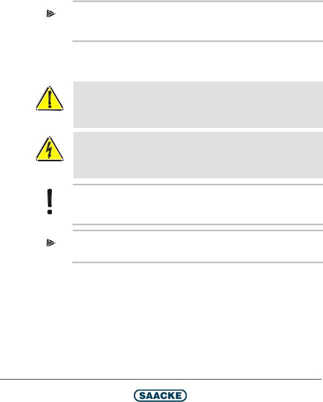
2.1Lifting Lugs
TMX029
Fig. 1: Lifting lugs
Note
Observe the information on weight and center of gravity in chapter "Dimensions /
Types".
Technical Documentation
12 / 78 |
BA-TEMINOX-GL-Duo2021-02 |
2021-06-22 |

TEMINOX® GL |
Transport, Storage and Packing |
|
|
|
|
2.2Safety Instructions for Transport
Warning! Risk of accidents during transport!
There is the risk of accidents during burner transport due to the heavy weight.
Do not stand under suspended loads.
Always use the appropriate aids when loading the burner (e.g. forklift or crane).
Warning! Risk of injuries from hoists too weak for the load!
Hoists or lifting equipment that are too weak for the load can tear.
Always select hoists or lifting equipment with sufficient load bearing capacity.
Use only tested and reliable hoists and lifting equipment, such as:
–Shackles, e.g. according to DIN 82101.
–Sling chains, e.g. according to DIN 5687 Product Grade 8
Caution!
The improper use of means of transport and tools (e.g. forklift or crane) bears the risk of damaging the burner or burner components.
2.3Checking the Delivery
SAACKE products are packed and checked before they leave the factory.
When the product is delivered, first check whether the packaging is intact. This would be the first indication that it has been transported correctly.
Check the product for transport damage.
2.4Reporting Transport Damage
If damage has occurred during transport, follow these procedures:
Record the transport damage on the freight documents and take a photograph and/or make a sketch of it.
Have the person responsible for the delivery (for example the truck driver) confirm that the damage was noticed by signing the freight documents.
Report the transport damage right away to SAACKE or whichever company supplied the product.
2.5Instructions for Storage
Only store the burner on the pallet or in the crate that it was delivered on/in.
Store the burner on safe and firm ground.
Keep all components, especially electrical, pneumatic and hydraulic components, dry, free of dust and at their correct temperature during storage. The relative humidity must be below 80 %.
Protect the burner with appropriate covering in the case of a long period of inactivity. Preserve all metal surfaces.
Technical Documentation
2021-06-22 |
BA-TEMINOX-GL-Duo2021-02 |
13 / 78 |

Transport, Storage and Packing |
TEMINOX® GL |
|
|
|
|
2.6Disposal of the Packaging
Dispose of all packaging correctly and ecologically.
When you do it, comply with the waste disposal regulations of the country in which you are working.
2.7Disposal of the Product
At the end of its service life the product must be disposed of correctly and ecologically.
When you do it, comply with the waste disposal regulations of the country in which you are working.
Technical Documentation
14 / 78 |
BA-TEMINOX-GL-Duo2021-02 |
2021-06-22 |
TEMINOX® GL |
Design and Function |
|
|
|
|
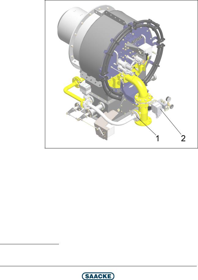
3 Design and Function
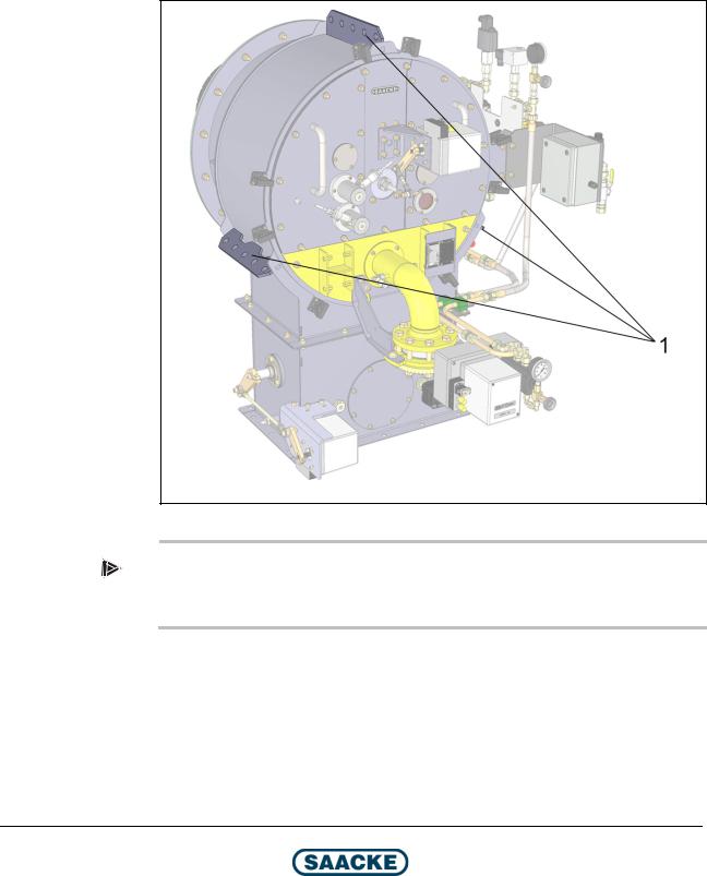
Note
A burner with standard equipment is shown. The equipment may vary depending on the plant. As several burner head variants are possible, the presentation of the burner head may differ.
TMX192
Fig. 2: Burner components (1)
1Right-hand maintenance cover
2Servomotor for stabilizing disk retract mechanism1
3Driving linkage for stabilizing disk retract mechanism
4Inspection glass
5Component connection box / control box for optional integrated burner control system
6Servomotor for oil flow controller / gas control damper
7Return line pressure gauge (with manual shut-off fitting)
8Power transmitter for oil flow controller / gas control damper2
9Gas control damper
10Pressure monitor (L) for combustion air
11Flame scanner (here: optional variant with 2 flame scanners)
12Left-hand maintenance cover
13Flange
14Burner head
1With TEMINOX G burners with burner head variant C02, a manual stabilizing disk retract mechanism is installed as the standard. The servomotor is only available as an option for this variant.
2Only TEMINOX GL (dual-fuel burner)
Technical Documentation
2021-06-22 |
BA-TEMINOX-GL-Duo2021-02 |
15 / 78 |
Design and Function |
TEMINOX® GL |
|
|
|
|
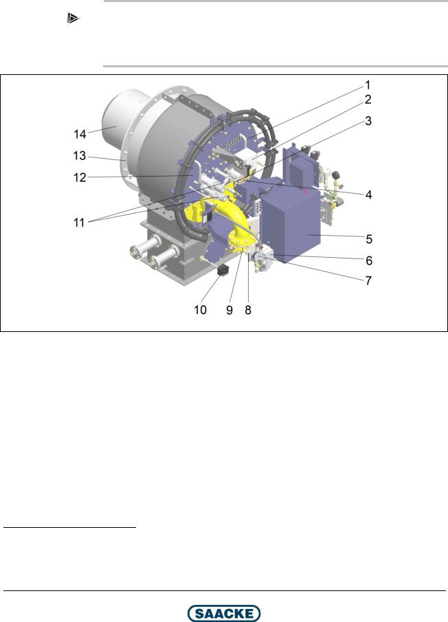
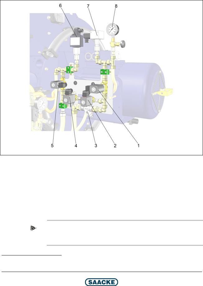
TMX193
Fig. 3: Burner components (2)
1Ignition valves (here: manual shut-off fitting in open position)
2Oil fittings block (see separate figure)
3Driving linkage for air control dampers
4Servomotor for air control dampers
5Manual shut-off fitting supply line / return line (mechanically coupled) (here: open position)
6Oil flow controller
Technical Documentation
16 / 78 |
BA-TEMINOX-GL-Duo2021-02 |
2021-06-22 |
TEMINOX® GL |
Design and Function |
|
|
|
|
Burner with Controlled Primary Gas (optional3)
TMX254
Fig. 4: Burner with controlled primary gas4
1Primary gas control damper
2Servomotor for primary gas control damper
3Standard with burner head variant C03
4Oil fittings and component connection box are hidden for a better overview
Technical Documentation
2021-06-22 |
BA-TEMINOX-GL-Duo2021-02 |
17 / 78 |
Design and Function |
TEMINOX® GL |
|
|
|
|
Oil Fittings Block
TMX015
Fig. 5: Oil fittings block5
1Rapid shut-off valve supply line
2Rapid shut-off valve control line supply line
3Dirt trap
4Rapid shut-off valve control line return line
5Rapid shut-off valve return line
6Pressure monitor (H)
7Pressure monitor (L)
8Pressure gauge for supply flow pressure (with manual shut-off fitting)
Not illustrated: Manual shut-off fitting supply line / return line (see figures above)
Note
Depending on the arrangement of the ignition medium and fuel fittings, the oil fittings block can have a laterally inversed design.
5 The example shows a monoblock burner, the duoblock burner has a similar design
Technical Documentation
18 / 78 |
BA-TEMINOX-GL-Duo2021-02 |
2021-06-22 |

TEMINOX® GL |
Design and Function |
|
|
|
|
Position of the Rating Plate and the Plate for Variant Designation
TMX194
Fig. 6: Position of the rating plate and the plate for variant designation
1 Rating plate and plate for variant designation
Technical Documentation
2021-06-22 |
BA-TEMINOX-GL-Duo2021-02 |
19 / 78 |
Construction of the Refractory Brickwork |
TEMINOX® GL |
|
|
|
|
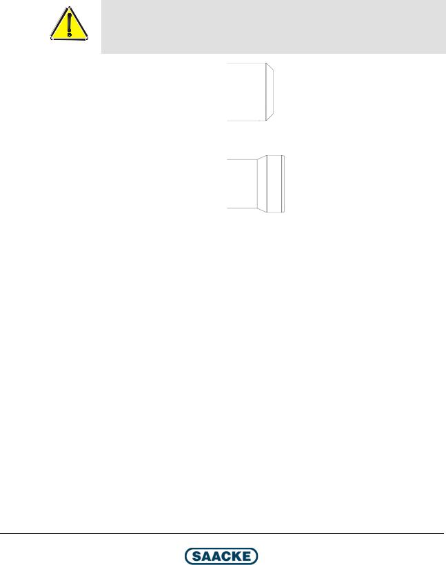
4 Construction of the Refractory Brickwork
Before the burner can be mounted on the heat generator, refractory brickwork must be constructed in keeping with the specifications in the present chapter.
The fireproof material for the refractory brickwork should have a AL2O3 content of at least 60 % and a spalling resistance of at least 15.
Warning!
The refractory brickwork must be parallel to the burner mounting plate and at right angle to the center line of the burner, as shown in the figure.
With this burner head variant
please continue with chapter “Burner Head Variant C01 / C03”.
With this burner head variant
please continue with chapter “Burner Head Variant C02”.
Technical Documentation
20 / 78 |
BA-TEMINOX-GL-Duo2021-02 |
2021-06-22 |
TEMINOX® GL |
Construction of the Refractory Brickwork |
|
|
|
|
4.1Burner Head Variant C01 / C03
W |
TMX053
Fig. 7: Refractory brickwork
|
|
|
|
|
|
|
Dimensions in mm |
|
|
||
|
Burner size |
|
W |
|
W |
|
X |
|
X |
|
R3 |
|
|
|
|
|
|
||||||
|
|
|
|
|
Monoblock |
|
Duoblock |
|
|||
|
|
|
Corrugated tube |
|
Plain tube |
|
|
|
|||
|
|
|
|
|
burners |
|
burners |
|
|
||
|
|
|
|
|
|
|
|
|
|
||
50 |
|
|
|
|
475 |
- |
|
|
|||
|
|
|
|
|
|
|
|
|
|||
70 |
|
|
|
|
475 |
470 |
|
See chapter “Dimensions / |
|||
100 |
|
|
|
≥130 |
480 |
475 |
|
Types”, section “Burner |
|||
|
|
|
≥130 |
|
and |
|
|
|
|
|
Mounting Plate”, dimension |
140 |
|
|
480 |
475 |
|
||||||
|
|
|
≤160 |
|
MBP1 (monoblock burners) / |
||||||
200 |
|
|
|
|
480 |
475 |
|
DBP1 (duoblock burners) |
|||
|
|
|
|
|
|
||||||
|
|
|
|
|
|
|
|
|
|||
280 |
|
|
|
|
495 |
490 |
|
|
|||
|
|
|
|
|
|
|
|
|
|
|
|
Technical Documentation
2021-06-22 |
BA-TEMINOX-GL-Duo2021-02 |
21 / 78 |

Construction of the Refractory Brickwork |
TEMINOX® GL |
|
|
|
|
4.2Burner Head Variant C02
W |
1 |
1 |
TMX043
Fig. 8: Refractory brickwork
1 |
Ceramic fibre mat (see chapter “Mounting Instructions”) |
|
|
||||||
|
|
|
|
|
|
|
|
|
|
|
|
|
|
|
|
Dimensions in mm |
|||
|
Burner size |
|
W |
|
X |
|
X |
|
R3 |
|
|
|
|
|
|||||
|
|
|
|
Monoblock |
|
Duoblock |
|
||
|
|
|
|
|
burners |
|
burners |
|
|
|
50 |
110 |
470 |
- |
|
|
|||
|
|
|
|
|
|
|
|||
|
70 |
130 |
490 |
485 |
|
See chapter “Dimensions / Types”, |
|||
|
100 |
145 |
510 |
505 |
|
section “Burner Mounting Plate”, |
|||
|
|
|
|
|
|
|
|
|
dimensions |
|
140 |
165 |
525 |
520 |
|
||||
|
|
MBP1 (monoblock burners) / |
|||||||
|
200 |
190 |
550 |
545 |
|
DBP1 (duoblock burners) |
|||
|
|
|
|||||||
|
|
|
|
|
|
|
|||
|
280 |
215 |
575 |
570 |
|
|
|||
|
|
|
|
|
|
|
|
|
|
Technical Documentation
22 / 78 |
BA-TEMINOX-GL-Duo2021-02 |
2021-06-22 |
TEMINOX® GL |
Mounting Instructions |
|
|
|
|
5 Mounting Instructions
Warning! Risk of injury and property damage due to the weight of the burner and the fan!
For all the work described in the following, always follow the instructions and safety instructions in the chapter "Transport, Storage and Packaging" before starting with any of the tasks described here!
Caution! Faulty mounting of the burner possible!
The correct construction of the refractory brickwork (refer to the chapter entitled "Construction of the Refractory Brickwork") is a requirement for mounting the burner.
Note
Observe section “Burner Mounting Plate” (chapter “Dimensions / Types“).
Caution!
There may still be a small amount of oil from the pressure test in the oil-carrying lines. Keep an oil drip tray ready during mounting and dispose of any oil correctly and ecologically.
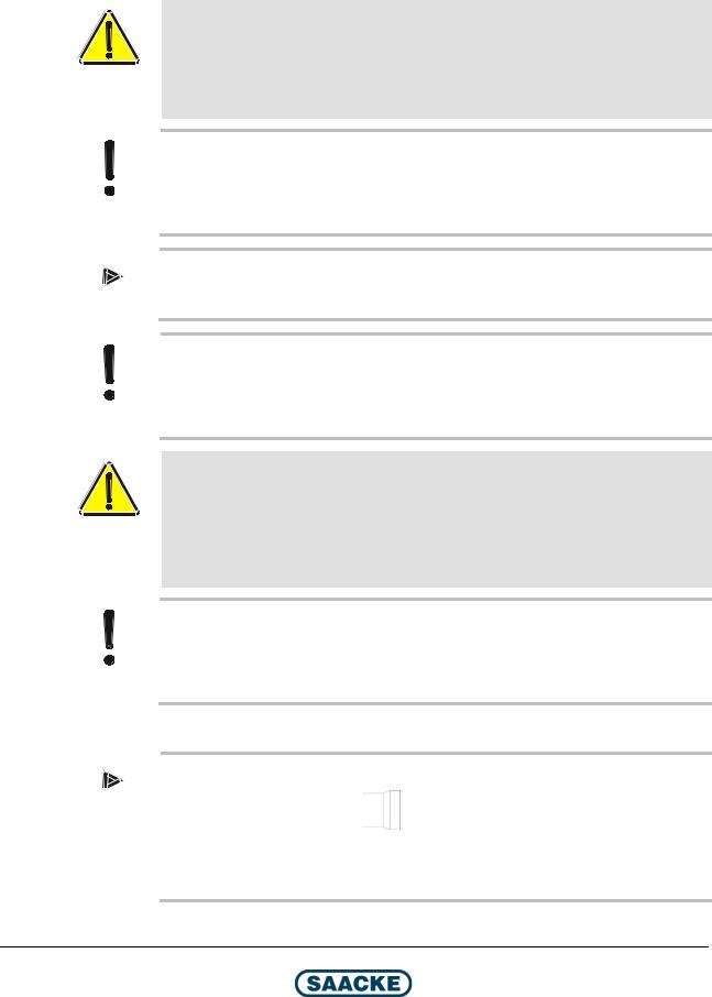
Warning! Health hazard due to ceramic fiber material!
Sealing cords and fiber plates for sealing contain ceramic high-temperature mineral fibers, which may be a health hazard in the case of direct contact or if fiber dust is inhaled. When handling sealing cords or fiber plates, wear appropriate protective clothing (overall that fits loosely on your throat and wrists, gloves, safety goggles with side shields, FFP2 respirators).
Caution!
The heat generator is subject to thermal expansion. Therefore flexible connectors must be fitted between all fixed lines and ducts and the burner. When connecting the flexible connectors, note the direction of the expansion.
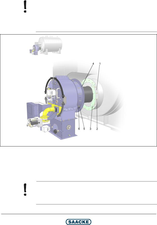
5.1Mounting the Burner
Note
With this burner head variant
please wind the supplied ceramic fiber mat around the thinner, cylindrical part of the burner head before installing the burner (see chapter “Construction of the Refractory Brickwork”)
Technical Documentation
2021-06-22 |
BA-TEMINOX-GL-Duo2021-02 |
23 / 78 |
Mounting Instructions |
TEMINOX® GL |
|
|
|
|
|
|
|
|
|
|
|
|
|
|
Caution! Faulty mounting of the burner possible!
Take into consideration the entry position of the combustion air when mounting the burner: In the figure, position 0° is shown as an example. This position differs depending on the plant configuration!
In addition, please have in mind that that gas connection module must always be in position 0°, independent of the plant configuration.
TMX049
Fig. 9: Mounting the burner
1Burner mounting plate
2Stud screw
3Gasket (fiber plate)
4Flange (burner)
5Washer
6Hexagonal nut
Caution!
Sealing cord and ceramic fiber plates shrink by up to 15 % during commissioning due to the effects of the temperature. Therefore retighten all of the mounting screws after the burner has been commissioned.
Technical Documentation
24 / 78 |
BA-TEMINOX-GL-Duo2021-02 |
2021-06-22 |
Loading...