

Page 1
OPERATOR’S MANUAL
MANUEL D’UTILISATION
MANUAL DEL OPERADOR
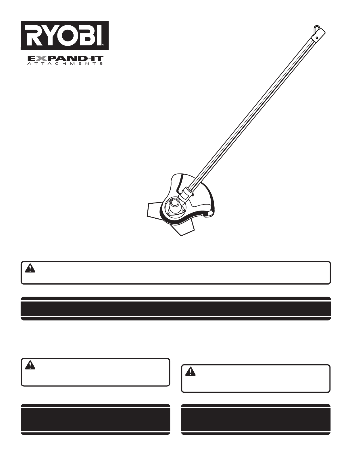
BRUSH CUTTER ATTACHMENT
ACCESSOIRE DE DÉBROUSSAILLEUSE
ACCESORIO PARA DESBROZADORA
RY15702
Your brush cutter attachment has been engineered and manufactured to our high standard for dependability, ease of operation, and operator safety. When properly cared for, it will give you years of rugged, trouble-free performance.
WARNING: To reduce the risk of injury, the user must read and understand the operator’s manual before using
this product.
Thank you for your purchase.
SAVE THIS MANUAL FOR FUTURE REFERENCE
Votre accessoire de débroussailleuse a été conçu et fabriqué
conformément aux strictes normes de fiabilité, simplicité d’emploi
et sécurité d’utilisation. Correctement entretenu, il vous donnera
des années de fonctionnement robuste et sans problème.
AVERTISSEMENT : Pour réduire les risques de
blessures, l’utilisateur doit lire et veiller à bien comprendre le
manuel d’utilisation avant d’employer ce produit.
Merci de votre achat.
Su nuevo accesorio para desbrozadora ha sido diseñado y
fabricado de conformidad con estrictas normas de calidad para
brindar fiabilidad, facilidad de uso y seguridad para el operador.
Con el debido cuidado, le brindará muchos años de sólido y
eficiente funcionamiento.
ADVERTENCIA: Para reducir el riesgo de lesiones,
el usuario debe leer y comprender el manual del operador antes
de usar este producto.
Le agradecemos su compra.
CONSERVER CE MANUEL POUR
FUTURE RÉFÉRENCE
GUARDE ESTE MANUAL PARA
FUTURAS CONSULTAS
Page 2
See this fold-out section for all of the figures referenced in the operator’s manual.
Consulter l’encart à volets afin d’examiner toutes les figures mentionnées dans le manuel d’utilisation.
Consulte esta sección desplegable para ver todas las figuras a las que se hace referencia en el manual del operador.
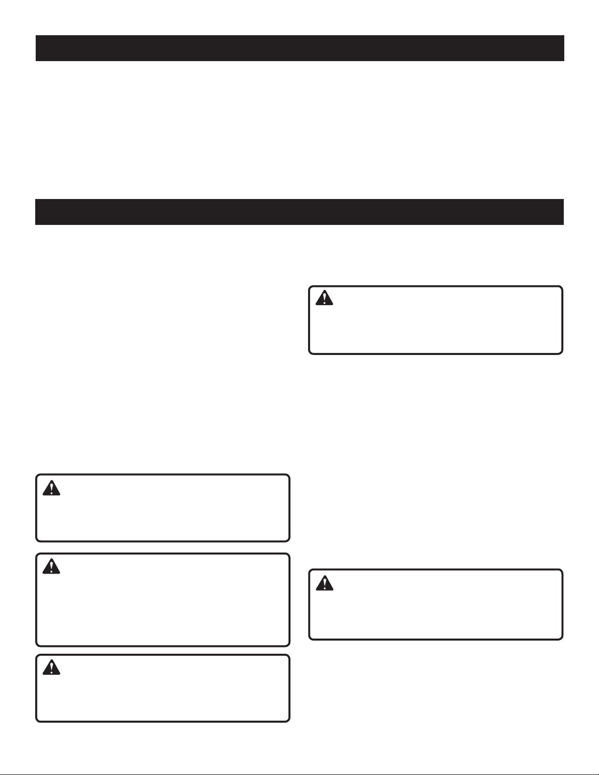
Fig. 1
A
B
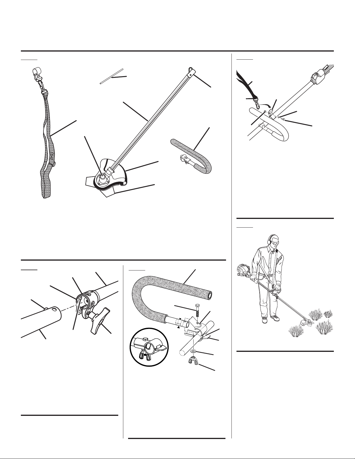
A - Shoulder harness assembly (bandoulière,
conjunto del arnés)
B - Gear head (carter d’engrenages, cabezal de
engranajes)
C - Gear head locking tool (outil de blocage de
tête de coupe, herramienta de fijación del
cabezal de engranajes)
D- Attachment shaft (arbre de l’accessoire, eje
del accesorio)
C
D
G
H
E - Hanger cap (capuchon de suspension, tapa
de suspensión)
F - J-handle assembly (poignée en « j », conjunto
de la manija “j”)
G - Brush cutter guard (pare-débris de
la débroussailleuse, protección de la
desbrozadora)
H
- Blade (lame, cuchilla)
Fig. 4
A
E
B
D
E
F
C
A - Shoulder harness (bandoulière, correa para el
hombro)
B - Latch (loquet, pestillo)
C - Lock nut (écrou de blocage, tuerca de
seguridad)
D - Shoulder harness hanger (accrochage de
bandoulière, correa para el hombro)
E - Lock washer (rondelle frein, arandela de
seguridad)
F - Bolt (boulon, perno)
F
Fig. 5
Fig. 2
A
B
C
D
F
G
E
A - Power head shaft (arbre moteur, cabezal
motor eje)
B - Coupler (coupleur, acoplador)
C - Guide recess (renfoncement du guide, hueco
guía)
D - Button (bouton, botón)
E - Attachment shaft (arbre de l’accessoire, eje
del accesorio)
F - Positioning hole (trou de positionnement,
orificio de posicionamiento)
G - Knob (bouton, perilla)
Fig. 3
D
C
A
G
B
E
F
A - Top clamp (collier supérieur, abrazadera
superior)
B - Bottom clamp (collier inférieure, abrazadera
inferior)
C - J-handle (poignée en « J », mango “J”)
D - Bolt (boulon, perno)
E - Flat washer (rondelle plate, arandela plana)
F - Wing nut (écrou à oreilles, tuerca de
mariposa)
G - Tab (ergot, orejeta)
ii
Page 3
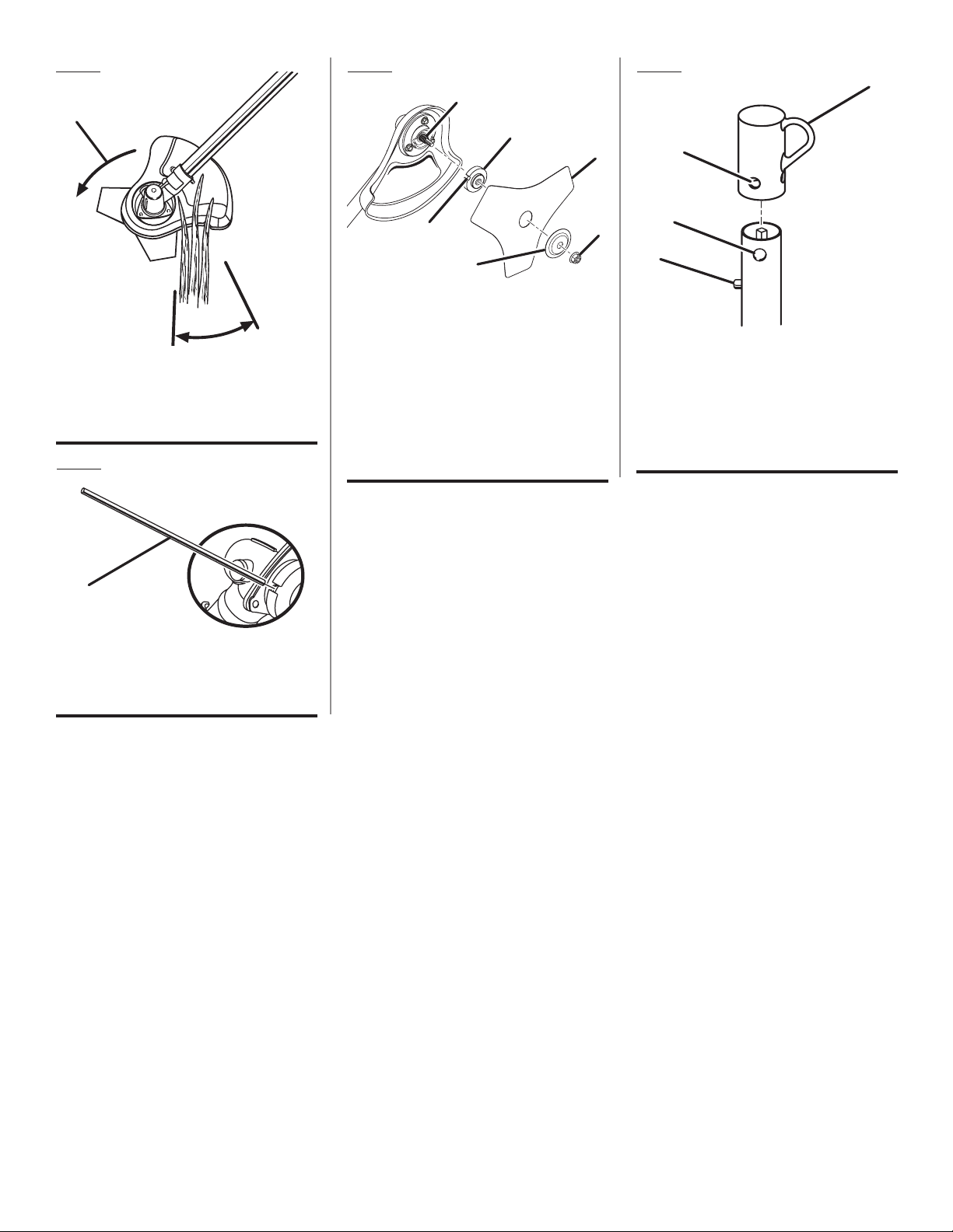
Fig. 6
A
Fig. 8 Fig. 9
A
B
C
A
B
B
A - Direction of rotation (sens de rotation, sentido
de rotación)
B - Cutting area (zone de coupe, área de corte)
Fig. 7
A
A - Gear head locking tool (outil de blocage de
tête de coupe, herramienta de fijación del
cabezal de engranajes)
D
F
E
A - Gear shaft (arbre d’engrenage, eje de
engranaje)
B - Flanged washer (rondelle à épaulement,
arandela de brida)
C - Blade (lame, hoja)
D - Slot (fente, ranura)
E - Cupped washer (rondelle bombée, arandela
cóncava)
F - Blade nut (écrou de lame, tuerca de la
cuchilla)
C
D
A - Hanger cap (capuchon de suspension, tapa
de suspensión)
B - Hole (trou, orificio)
C - Secondary hole (trou secondaire, orificio
secundario)
D - Button (bouton, botón)
iii
Page 4

TABLE OF CONTENTS
TABLE DES MATIÈRES / ÍNDICE DE CONTENIDO
Introduction ......................................................................................................................................................................2
Introduction / Introducción
General Safety Rules ........................................................................................................................................................ 3
Règles de sécurité générales / Reglas de seguridad generales
Specific Safety Rules .....................................................................................................................................................3-4
Règles de sécurité particulières / Reglas de seguridad específicas
Symbols ............................................................................................................................................................................ 5
Symboles / Símbolos
Features ............................................................................................................................................................................6
Caractéristiques / Características
Assembly .......................................................................................................................................................................6-7
Assemblage / Armado
Operation .......................................................................................................................................................................7-8
Utilisation / Funcionamiento
Maintenance ..................................................................................................................................................................... 9
Entretien / Mantenimiento
Warranty .........................................................................................................................................................................10
Garantie / Garantía
Illustrated Parts List ...................................................................................................................................................12-13
Liste des pièces illustrées / Lista de piezas ilustradas
Parts Ordering and Service ...............................................................................................................................Back Page
Commande de pièces et réparation / Pedidos de piezas y servicio ......................................................... Page arrière / Pág. posterior
INTRODUCTION
INTRODUCTION / INTRODUCCIÓN
This product has many features for making its use more pleasant and enjoyable. Safety, performance, and dependability
have been given top priority in the design of this product making it easy to maintain and operate.
* * *
Ce produit offre de nombreuses fonctions destinées à rendre son utilisation plus plaisante et satisfaisante. Lors de la
conception de ce produit, l’accent a été mis sur la sécurité, les performances et la fiabilité, afin d’en faire un outil facile à
utiliser et à entretenir.
* * *
Este producto ofrece numerosas características para hacer más agradable y placentero su uso. En el diseño de este producto
se ha conferido prioridad a la seguridad, el desempeño y la fiabilidad, por lo cual se facilita su manejo y mantenimiento.
2
Page 5

GENERAL SAFETY RULES
WARNING:
Read and understand all instructions. Failure to fol-
low all instructions listed below, may result in electric
shock, fire, and/or serious personal injury.
SAVE THESE INSTRUCTIONS
Read these instructions and the instructions for the power
head thoroughly before using the attachment.
Know the tool. Read and understand the operator’s
manual and observe the warnings and instruction labels
affixed to the tool.
Do not allow children or untrained individuals to use this
unit.
Wear safety glasses or goggles that are marked to comply
with ANSI Z87.1 standard and hearing protection when
operating this unit.
Wear heavy long pants, a long-sleeved shirt, boots, and
gloves. Do not wear loose fitting clothing, short pants,
jewelry of any kind, or go barefoot.
Secure long hair so it is above shoulder level to prevent
entanglement in any moving parts.
Keep all bystanders, children, and pets at least 50 ft.
away. Bystanders should be encouraged to wear eye
protection.
Stay alert, watch what you are doing, and use common
sense when operating a power tool. Do not use tool
while tired or under the influence of drugs, alcohol, or
medication. A moment of inattention while operating
power tools may result in serious personal injury.
Do not operate in poor lighting.
Do not overreach. Keep proper footing and balance at all
times. Proper footing and balance enables better control
of the tool in unexpected situations.
Keep all parts of your body away from any moving part.
Do not touch areas around the muffler or cylinder of the
power head. These parts get hot from operation. Failure
to heed this warning could result in possible serious
personal injury.
Always stop the engine and remove the spark plug wire
before making any adjustments or repairs except for
carburetor adjustments.
Inspect unit before each use for loose fasteners and
damaged or missing parts. Correct before using the
attachment. Failure to do so can cause serious injury.
Use only original manufacturer’s replacement parts.
Failure to do so may cause poor performance, possible
injury, and will void your warranty.
Do not, under any circumstance, use any attachment or
accessory on this product, which was not provided with
the product, or identified as appropriate for use with this
product in the operator’s manual.
Avoid dangerous environments. Do not use the attachment
in damp or wet locations. Do not use in rain.
Use the right attachment. Do not use attachment for any
job except that for which it is intended.
SPECIFIC SAFETY RULES
Ensure handle is mounted in accordance with the assem-
bly instructions in this manual.
Do not attach blade without proper installation of all
required parts. Failure to use proper parts can cause the
blade to fly off and seriously injure the operator and/or
bystanders.
Always use a blade in good condition. A worn blade is
more likely to snag and thrust.
After engine stops, keep rotating blade in thicker weeds
or pulpy stalks until it stops.
Do not operate the brush cutter unless the brush cutter
guard is firmly secured in place and in good condition.
Use heavy gloves when operating the brush cutter and
when installing or removing blades.
Always stop the engine and remove the spark plug wire
before attempting to remove any obstruction caught or
jammed in the blade or before removing and installing
the blade.
3 — English
Do not attempt to touch or stop blade when it is rotating.
A coasting blade can cause injury while it continues
to spin after the engine is stopped or throttle trigger
released.
Maintain proper control until the blade has completely
stopped rotating.
Replace any blade that has been bent, warped, cracked,
chipped, or damaged. Always make sure blade is installed
correctly and securely fastened before each use. Failure
to do so can cause serious injury.
Use only the manufacturer’s replacement TRI-ARC® blade
intended for use on this brush cutter. Do not use any other
blade. To install any other brand blade or cutting head to
this brush cutter can result in serious personal injury.
The TRI-ARC® blade is suited for cutting thicker weeds
or pulpy stalks only. Do not use for any other purpose.
Never use the TRI-ARC® blade to cut woody brush.
Page 6

SPECIFIC SAFETY RULES
Exercise extreme caution when using the blade with this
unit. Blade thrust is the reaction that may occur when
the spinning blade contacts anything it cannot cut. This
contact may cause the blade to stop for an instant, and
suddenly “thrust” the unit away from the object that was
hit. This reaction can be violent enough to cause the
operator to lose control of the unit. Blade thrust can occur
without warning if the blade snags, stalls, or binds. This is
more likely to occur in areas where it is difficult to see the
material being cut. For cutting ease and safety, approach
the weeds being cut from the right to the left. In the event
an unexpected object or woody stock is encountered,
this approach could minimize the blade thrust reaction.
Never cut any material over 1/2 in. diameter.
Always wear the shoulder harness when using the brush
cutter and adjust to a comfortable operating position.
Maintain a firm grip on both handles while cutting with a
blade. Keep the blade away from body and below waist
level. Never use the brush cutter with the blade located
30 in. or more above the ground level.
To prevent electrical shock or serious personal injury, do
not use this product with any electric power head.
Save these instructions. Refer to them frequently and
use them to instruct others who may use this product.
If you loan someone this product, loan them these
instructions also to prevent misuse of the product and
possible injury.
4 — English
Page 7
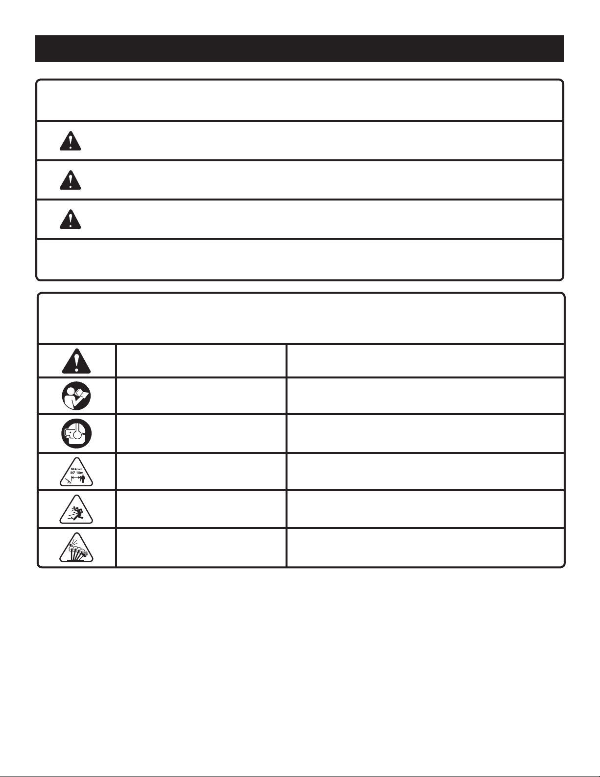
SYMBOLS
The following signal words and meanings are intended to explain the levels of risk associated with this product.
SYMBOL SIGNAL MEANING
DANGER:
WARNING:
CAUTION:
NOTICE:
Some of the following symbols may be used on this product. Please study them and learn their meaning. Proper
interpretation of these symbols will allow you to operate the product better and safer.
Indicates an imminently hazardous situation, which, if not avoided, will result
in death or serious injury.
Indicates a potentially hazardous situation, which, if not avoided, could result
in death or serious injury.
Indicates a potentially hazardous situation, which, if not avoided, may result in
minor or moderate injury.
(Without Safety Alert Symbol) Indicates important information not related to an
injury hazard, such as a situation that may result in property damage.
SYMBOL NAME EXPLANATION
Safety Alert Symbol Precautions that involve your safety.
Read the Operator’s Manual
To reduce the risk of injury, user must read and understand
operator’s manual before using this product.
Wear eye protection which is marked to comply with ANSI
Eye and Hearing Protection
Keep Bystanders Away Keep all bystanders at least 50 ft. away.
Ricochet
Blade Thrust
Z87.1 as well as hearing protection when operating this
equipment.
Thrown objects can ricochet and result in personal injury
or property damage.
Beware of blade thrust. Products authorized for blade use will
display this symbol to warn of blade thrust.
5 — English
Page 8
FEATURES
PRODUCT SPECIFICATIONS
Blade Cutting Width ..................................................... 8 in.
Weight ................................................................... 3.25 lbs.
KNOW YOUR BRUSH CUTTER ATTACHMENT
See Figure 1.
The safe use of this product requires an understanding of the information on the product and in this operator’s manual as
well as a knowledge of the project you are attempting. Before use of this product, familiarize yourself with all operating
features and safety rules.
ASSEMBLY
UNPACKING
This product requires assembly.
Carefully remove the items from the box. Make sure that
all items listed in the packing list are included.
Inspect the product carefully to make sure no breakage
or damage occurred during shipping.
Do not discard the packing material until you have care-
fully inspected and satisfactorily operated the product.
If any parts are damaged or missing, please call
1-800-860-4050 for assistance.
PACKING LIST
Ryobi® Expand-It™
J-Handle Assembly
Shoulder Harness Assembly
Hardware Bag
Gear Head Locking Tool
Operator’s Manual
Brush Cutter Attachment
WARNING:
If any parts are damaged or missing do not operate this
product until the parts are replaced. Failure to heed this
warning could result in serious personal injury.
WARNING:
Do not attempt to modify this product or create accessories not recommended for use with this product. Any
such alteration or modification is misuse and could result
in a hazardous condition leading to possible serious
personal injury.
ATTACHING THE BRUSH CUTTER
ATTACHMENT TO THE POWER HEAD
See Figure 2.
WARNING:
Never attach or adjust any attachment while power head
is running. Failure to stop the engine may cause serious
personal injury.
The brush cutter attachment connects to the power head
by means of a coupler device.
Remove the hanger cap from the attachment.
Loosen the knob on the coupler of the power head
shaft.
Push in the button located on the brush cutter attachment.
Align the button with the guide recess on the extension
shaft coupler and slide the two shafts together. Rotate
attachment until button locks into the positioning hole.
Tighten the knob securely.
NOTE: If the buttons do not release completely in the
positioning holes, the shafts are not locked into place.
Slightly rotate from side to side until the button is locked
into place.
NOTE: Use only the specified positioning hole for this
attachment.
WARNING:
Be certain the knob is fully tightened before operating
equipment. Check it periodically for tightness during use
to avoid serious injury.
WARNING:
Do not connect to power head until assembly is complete.
Failure to comply could result in accidental starting and
possible serious personal injury.
6 — English
REMOVING THE ATTACHMENT FROM THE
POWER HEAD
For removing or changing the attachment:
Stop the engine.
Loosen the knob.
Push in the button and twist the shafts to remove and
separate ends.
Page 9
ASSEMBLY
ATTACHING THE “J” HANDLE
See Figure 3.
The “J” handle must be used to ensure the best control
and maximize operator safety when using the brush cutter.
If the power head to which the brush cutter attachment will
be mounted does not have such a handle, install the handle
provided.
Place the bottom J-handle clamp on the drive shaft as
shown. Insert the tab on the top J-handle clamp into the
slot on the bottom J-handle clamp.
Insert the end of the J-handle between the clamps so that
holes align and handle will be located to the operator’s left.
Push the bolt through the clamp and handle.
Install flat washer and wing nut to hold the assembly in
place.
Adjust the position of the handle.
Tighten the wing nut securely.
OPERATION
INSTALLING THE SHOULDER HARNESS AND
STRAP HANGER
See Figure 4.
Pull apart the ends of the shoulder harness hanger to
expand slightly.
Slide the hanger over the power head shaft immediately
behind the “J” handle.
Squeeze hanger ends together to retighten.
Install the bolt, lock washer, and lock nut to secure.
Connect the latch on the shoulder harness to the strap
hanger.
WARNING:
Do not allow familiarity with this product to make you
careless. Remember that a careless fraction of a second is
sufficient to inflict serious injury.
WARNING:
Always wear safety goggles or safety glasses with side
shields when operating power tools. Failure to do so
could result in objects being thrown into your eyes
resulting in possible serious injury.
WARNING:
Do not use any attachments or accessories not
recommended by the manufacturer of this product. The
use of attachments or accessories not recommended
can result in serious personal injury.
APPLICATIONS
You may use this product for the purpose listed below:
Cutting thicker weeds and pulpy stalks only
WARNING:
To avoid burns from hot surfaces, never operate unit with
the bottom of the engine above waist level.
OPERATING THE BRUSH CUTTER
See Figures 5 - 6.
Hold the brush cutter with your right hand on the rear handle
and your left hand on the “J” handle. Keep a firm grip with
both hands while in operation. Brush cutter should be held
at a comfortable position with the trigger handle about hip
height. Maintain your grip and balance on both feet. Position yourself so that you will not be drawn off balance by the
kickback reaction of the cutting blade.
Adjust the shoulder harness to position the brush cutter
at a comfortable operating position and to ensure that the
shoulder harness will reduce the risk of operator contact
with the blade.
Ensure the blade has come to a complete stop before setting
the brush cutter down.
BLADE THRUST
Exercise extreme caution when using the blade with this
unit. Blade thrust is the reaction that may occur when the
spinning blade contacts anything it cannot cut. This contact
may cause the blade to stop for an instant and suddenly
“thrust” the unit away from the object that was hit. This reaction can be violent enough to cause the operator to lose
control of the unit. Blade thrust can occur without warning
if the blade snags, stalls, or binds. This is more likely to occur in areas where it is difficult to see the material being cut.
For cutting ease and safety, approach the weeds being cut
with the brush cutter from the right to the left. In the event
an unexpected object or woody stock is encountered, this
practice could minimize the blade thrust reaction.
7 — English
Page 10

OPERATION
TRI-ARC® BLADE
The TRI-ARC® blade is suited only for thicker weeds and
pulpy stalks. When the blade becomes dull, it can be turned
over to extend the life of the blade. Do not sharpen the TRIARC® blade.
Use only TRI-ARC® blade, part number 06297, available at
your service center.
CUTTING TECHNIQUE - BLADE
WARNING:
Extreme care must be taken when using blades to ensure
safe operation. For safe operation when using the blade,
refer to Specific Safety Rules earlier in this manual.
Always hold brush cutter on your right side with both
hands when operating. Use a firm grip on both handles.
Maintain your grip and balance on both feet. Position
yourself so that you will not be drawn off balance by the
kickback reaction of the cutting blade.
Inspect and clear the area of any hidden objects such as
glass, rocks, concrete, fencing, wire, wood, metal, etc.,
which can be thrown or entangled in the blade.
Never use blades near sidewalks, fencing, posts, build-
ings or other immovable objects.
Never use a blade after hitting a hard object without first
inspecting it for damage. Do not use if any damage is
detected.
The unit is used for cutting from the right to the left in a
broad sweeping action from side to side.
Use only the TRI-ARC® blade. To install any other brand
blade or cutting head to this brush cutter could result in
serious personal injury.
8 — English
Page 11
MAINTENANCE
WARNING:
When servicing, use only identical replacement parts.
Use of any other parts may create a hazard or cause
product damage.
WARNING:
Always wear safety goggles or safety glasses with side
shields during power tool operation or when blowing
dust. If operation is dusty, also wear a dust mask.
WARNING:
Before inspecting, cleaning, or servicing the machine,
shut off engine, wait for all moving parts to stop, and
disconnect spark plug wire and move it away from spark
plug. Failure to follow these instructions can result in
serious personal injury or property damage.
GENERAL MAINTENANCE
Avoid using solvents when cleaning plastic parts. Most
plastics are susceptible to damage from various types of
commercial solvents and may be damaged by their use. Use
clean cloths to remove dirt, dust, oil, grease, etc.
REPLACING THE TRI-ARC® BLADE
See Figures 7 - 8.
To remove blade:
Align the slot in the flanged washer with the slot in the
gear head.
Place the gear head locking tool through the slot in the
flanged washer and gear head.
Remove the blade nut by turning it clockwise (left-handed
threads).
Remove the cupped washer and the blade.
To install blade:
Place flanged washer over the gear shaft with the hollow
side toward the brush cutter guard.
Center the blade on the flanged washer, making sure the
blade fits flat and the raised hub goes through the hole
in the blade.
Install the cupped washer with the raised center away
from the blade.
Place the blade nut onto the gear shaft.
Insert the head locking tool through the flanged washer
and gear head.
Install the blade nut by turning it counterclockwise (left-
handed threads).
Tighten the blade nut and torque to 120 in.lb. minimum
(finger tight plus 1/2 turn).
WARNING:
Do not at any time let brake fluids, gasoline, petroleumbased products, penetrating oils, etc., come in contact
with plastic parts. Chemicals can damage, weaken, or destroy plastic, which may result in serious personal injury.
Only the parts shown on the parts list are intended to be
repaired or replaced by the customer. All other parts should
be replaced at an authorized service center.
ATTACHING THE STORAGE HANGER
See Figure 9.
There are two ways to hang the attachment for storage.
To use the hanger cap, push in the button and place the
hanger cap over the end of the attachment shaft. Slightly
rotate the cap from side to side until the button locks into
place.
The secondary hole in the attachment shaft can be used
for hanging purposes as well.
STORING THE ATTACHMENT
Clean the attachment thoroughly and lubricate before
storing.
Store the attachment in a dry, well-ventilated place that
is inaccessible to children.
Keep away from corrosive agents such as garden chemi-
cals and de-icing salts.
9 — English
Page 12

WARRANTY
LIMITED WARRANTY STATEMENT
Techtronic Industries North America, Inc., warrants to the
original retail purchaser that this RYOBI® brand outdoor
product is free from defect in material and workmanship
and agrees to repair or replace, at Techtronic Industries
North America, Inc.’s, discretion, any defective product
free of charge within these time periods from the date of
purchase.
Three years if the product is used for personal, family
or household use;
90 days, if used for any other purpose, such as
commercial or rental.
This warranty extends to the original retail purchaser
only and commences on the date of the original retail
purchase.
Any part of this product found in the reasonable judgment
of Techtronic Industries North America, Inc. to be defective
in material or workmanship will be repaired or replaced
without charge for parts and labor by an authorized service
center for RYOBI® brand outdoor products (Authorized
Ryobi Service Center).
The product, including any defective part, must be returned
to an authorized Ryobi service center within the warranty
period. The expense of delivering the product to the service
center for warranty work and the expense of returning it
back to the owner after repair or replacement will be paid
by the owner. Techtronic Industries North America, Inc.’s,
responsibility in respect to claims is limited to making the
required repairs or replacements and no claim of breach of
warranty shall be cause for cancellation or rescission of the
contract of sale of any RYOBI® brand outdoor product. Proof
of purchase will be required by the dealer to substantiate
any warranty claim. All warranty work must be performed
by an authorized service dealer.
This warranty is limited to ninety (90) days from the date
of original retail purchase for any RYOBI® brand outdoor
product that is used for rental or commercial purposes, or
any other income-producing purpose.
This warranty does not cover any product that has been
subject to misuse, neglect, negligence, or accident, or that
has been operated in any way contrary to the operating
instructions as specified in this operator’s manual. This
warranty does not apply to any damage to the product that
is the result of improper maintenance or to any product
that has been altered or modified. The warranty does not
extend to repairs made necessary by normal wear or by the
use of parts or accessories which are either incompatible
with the RYOBI® brand outdoor product or adversely affect
its operation, performance, or durability. In addition, this
warranty does not cover:
A. Tune-ups – Spark Plugs, Carburetor, Carburetor
Adjustments, Ignition, Filters
B. Wear items – Bump Knobs, Outer Spools, Cutting
Lines, Inner Reels, Starter Pulleys, Starter Ropes, Drive
Belts, Tines, Felt Washers, Hitch Pins, Mulching Blades,
Blower Fans, Blower and Vacuum Tubes, Vacuum Bag
and Straps, Guide Bars, Saw Chains
Techtronic Industries North America, Inc., reserves the
right to change or improve the design of any RYOBI® brand
outdoor product without assuming any obligation to modify
any product previously manufactured.
ALL IMPLIED WARRANTIES ARE LIMITED IN DURATION
TO THE STATED WARRANTY PERIOD. ACCORDINGLY,
ANY SUCH IMPLIED WARRANTIES INCLUDING
MERCHANTABILITY, FITNESS FOR A PARTICULAR
PURPOSE, OR OTHERWISE, ARE DISCLAIMED
IN THEIR ENTIRETY AFTER THE EXPIRATION OF
THE APPROPRIATE THREE-YEAR OR NINETY-DAY
WARRANTY PERIOD. TECHTRONIC INDUSTRIES
NORTH AMERICA, INC.’S, OBLIGATION UNDER THIS
WARRANTY IS STRICTLY AND EXCLUSIVELY LIMITED TO
THE REPAIR OR REPLACEMENT OF DEFECTIVE PARTS
AND TECHTRONIC INDUSTRIES NORTH AMERICA,
INC., DOES NOT ASSUME OR AUTHORIZE ANYONE
TO ASSUME FOR THEM ANY OTHER OBLIGATION.
SOME STATES DO NOT ALLOW LIMITATIONS ON HOW
LONG AN IMPLIED WARRANTY LASTS, SO THE ABOVE
LIMITATION MAY NOT APPLY TO YOU. TECHTRONIC
INDUSTRIES NORTH AMERICA, INC., ASSUMES NO
RESPONSIBILITY FOR INCIDENTAL, CONSEQUENTIAL,
OR OTHER DAMAGES INCLUDING, BUT NOT LIMITED
TO, EXPENSE OF RETURNING THE PRODUCT TO AN
AUTHORIZED RYOBI SERVICE CENTER AND EXPENSE
OF DELIVERING IT BACK TO THE OWNER, MECHANIC’S
TRAVEL TIME, TELEPHONE OR TELEGRAM CHARGES,
RENTAL OF A LIKE PRODUCT DURING THE TIME
WARRANTY SERVICE IS BEING PERFORMED, TRAVEL,
LOSS OR DAMAGE TO PERSONAL PROPERTY, LOSS
OF REVENUE, LOSS OF USE OF THE PRODUCT, LOSS
OF TIME, OR INCONVENIENCE. SOME STATES DO NOT
ALLOW THE EXCLUSION OR LIMITATION OF INCIDENTAL
OR CONSEQUENTIAL DAMAGES, SO THE ABOVE
LIMITATION OR EXCLUSION MAY NOT APPLY TO YOU.
This warranty gives you specific legal rights, and you may
also have other rights which vary from state to state.
This warranty applies to all RYOBI® brand outdoor products
manufactured by or for Techtronic Industries North America,
Inc., and sold in the United States and Canada.
To locate your nearest Authorized Ryobi Service Center,
dial 1-800-860-4050.
10 — English
Page 13

NOTES
11 — English
Page 14

RÈGLES DE SÉCURITÉ GÉNÉRALES
AVERTISSEMENT :
Lire et veiller à bien comprendre toutes les
instructions. Le non-respect de toutes les instructions
ci-dessous peut entraîner un choc électrique, un incendie
et/ou des blessures graves.
CONSERVER CES INSTRUCTIONS
Lire attentivement ces instructions et celles du moteur
avant d’utiliser cet accessoire.
Apprendre à connaître l’outil. Lire et veiller à bien
comprendre le manuel de l’opérateur et observer les
avertissements et les instructions des autocollants
apposés sur l’outil.
Ne pas laisser des enfants ou personnes n’ayant pas reçu
une formation adéquate utiliser cet outil.
Pour utiliser cet appareil, porter des lunettes de sécurité
certifiées conformes à la norme ANSI Z87.1 ainsi qu’une
protection auditive.
Porter des pantalons longs, un vêtement à manches
longues, des bottes et des gants. Ne pas porter de
vêtements amples, shorts, bijoux quels qu’ils soient et
ne pas travailler pieds nus.
Attacher les cheveux longs pour les maintenir au-dessus
des épaules, afin qu’ils ne se prennent pas dans les
pièces en mouvement.
Garder les badauds, enfants et animaux domestiques à
une distance minimum de 15 m (50 pi). Recommander aux
personnes présente de porter une protection oculaire.
Rester attentif, prêter attention au travail, et faire preuve
de bon sens lors de l’utilisation de tout outil électrique. Ne
pas utiliser cet outil en état de fatigue ou sous l’influence
d’alcool, de drogues ou de médicaments. Un moment
d’inattention pendant l’utilisation d’un outil électrique
peut entraîner des blessures graves.
Ne pas travailler sous un éclairage insuffisant.
Ne pas travailler hors de portée. Toujours se tenir bien
campé et en équilibre. Des pieds bien campés et un bon
équilibre permettent de mieux contrôler l’outil en cas de
situation imprévue.
Garder toutes les parties du corps à l’écart des pièces
en mouvement.
Ne pas toucher les zones autour de l’échappement ou du
cylindre du moteur. Ces pièces deviennent très chaudes
en cours de fonctionnement. Ne pas prendre cette
précaution pourrait entraîner des blessures graves.
Toujours arrêter le moteur et débrancher le fil de la bougie
avant d’effectuer tout entretien ou réglage, à l’exception
des réglages du carburateur.
Inspecter l’appareil avant chaque utilisation pour
s’assurer qu’il n’y a pas de fixations desserrées ou de
pièces endommagées ou manquantes. Effectuer les
corrections requises avant d’utiliser l’accessoire. Ne pas
prendre cette précaution peut entraîner des risques de
blessures graves.
Utiliser exclusivement des pièces de rechange
d’origine. Toute dérogation peut entraîner un mauvais
fonctionnement, des blessures graves et l’annulation de
la garantie.
N’utiliser en aucun cas un accessoire non fourni avec le
produit, ou indiqué comme pouvant être utilisé sur l’outil
dans le manuel d’utilisation.
Éviter les environnements dangereux. Ne pas utiliser
l’accessoire dans des endroits humides ou mouillés. Ne
pas utiliser sous la pluie.
Utiliser l’accessoire approprié. Ne pas utiliser l’accessoire
dans une application pour laquelle il n’a pas été prévu.
RÈGLES DE SÉCURITÉ PARTICULIÈRES
S’assurer que la poignée est montée conformément aux
instructions de montage qui figurent dans ce guide.
Ne pas fixer la lame avant d’avoir installé toutes les pièces
requises. L’utilisation des mauvaises pièces pourrait
causer l’éjection de la lame, ce qui exposerait l’opérateur
et les personnes se tenant à proximité à des risques de
blessures graves.
Toujours utiliser une lame en bon état. Une lame
usée a plus tendance à s’accrocher et s’écarter
brusquement.
Une fois le moteur arrêté, garder la lame en rotation dans
de l’herbe épaisse ou des tiges pulpeuses, jusqu’à ce
qu’elle s’immobilise.
3 — Français
Ne pas utiliser la débroussailleuse si la garde de lame
n’est pas solidement assujettie et en bon état.
Porter des gants épais lors de l’utilisation de la
débroussailleuse, ainsi que du retrait et de l’installation
des lames.
Toujours arrêter le moteur avant d’essayer de retirer des
objets pris dans la lame ou la bloquant et avant d’installer
ou retirer la lame.
Ne pas essayer de toucher ou d’arrêter la lame en rotation.
Une lame continuant de tourner au débrayé une fois que
le moteur est arrêté et la gâchette relâchée peut causer
des blessures.
Page 15

RÈGLES DE SÉCURITÉ PARTICULIÈRES
Garder le contrôle de l’outil jusqu’à ce que la lame soit
complètement immobilisée.
Toute lame déformée, gauchie, fissurée, ébréchée ou
endommagée doit être remplacée. S’assurer que la lame
est correctement installée et solidement assujettie avant
chaque utilisation. Ne pas prendre cette précaution peut
entraîner des risques de blessures graves.
Utiliser uniquement des lames TRI-ARC® d’origine
conçues pour cette débroussailleuse. Ne pas utiliser
d’autres lames. L’utilisation d’une tête de coupe d’autre
marque sur ce taille-bordures peut entraîner des
blessures graves.
La lame TRI-ARC® est conçue pour couper des herbes
épaisses et plantes pulpeuses uniquement. Ne pas
l’utiliser pour d’autres applications.
Ne jamais utiliser la lame TRI-ARC® pour couper de la
végétation ligneuse.
Lorsqu’il est équipé d’une lame, utiliser cet outil avec
la plus extrême prudence. Un ricochet de lame peut se
produire lorsque celle-ci entre en contact avec un objet
qu’elle ne peut pas couper. Ce contact peut causer
un bref blocage de la lame, qui fait « ricocher » l’outil
en direction opposée de l’objet heurté. Cette réaction
peut être assez violente pour faire perdre le contrôle de
l’outil. Un ricochet peut se produire à tout instant si la
lame est bloquée, stoppe ou se coince. Ce problème
est plus susceptible de se produire dans les endroits
où il n’est pas possible de voir le matériau coupé. Pour
faciliter la coupe et assurer la sécurité travailler avec un
mouvement de droite à gauche. Si la lame heurte un
obstacle imprévu ou du bois, ceci approche peut réduite
la force du ricochet.
Ne jamais couper de tiges de plus de 13 mm (1/2 po) de
diamètre.
Toujours utiliser la bandoulière et la régler pour pouvoir
travailler confortablement.
Tenir fermement les deux poignées pendant les travaux
de coupe avec une lame. Garder la lame loin du corps,
au-dessous du niveau de la taille. Ne jamais tailler avec la
débroussailleuse avec la lame à plus de 762 mm (30 po)
du sol.
Pour éviter les risques de choc électrique ou de blessures
graves, ne pas utiliser ce produit avec un bloc moteur à
alimentation secteur.
Conserver ces instructions. Les consulter fréquemment et
les utiliser pour instruire les autres utilisateurs éventuels.
Si cet produit est prêté, il doit être accompagné de
ces instructions, afin d’éviter un usage incorrect et
d’éventuelles blessures.
4 — Français
Page 16

SYMBOLES
Les termes de mise en garde suivants et leur signification ont pour but d’expliquer le degré de risques associé à
l’utilisation de ce produit.
SYMBOLE SIGNAL SIGNIFICATION
DANGER :
AVERTISSEMENT :
ATTENTION :
AVIS :
Certains des symboles ci-dessous peuvent être présents sur la produit. Veiller à les étudier et à apprendre leur
signification. Une interprétation correcte de ces symboles permettra d’utiliser la produit plus efficacement et de
réduire les risques.
Indique une situation extrêmement dangereuse qui, si elle n’est pas évitée,
aura pour conséquences des blessures graves ou mortelles.
Indique une situation potentiellement dangereuse qui, si elle n’est pas évitée,
pourrait entraîner des blessures graves ou mortelles.
Indique une situation potentiellement dangereuse qui, si elle n’est pas évitée,
pourraît entraîner des blessures légères ou de gravité modérée.
(Sans symbole d’alerte de sécurité) Indique une information importante
ne concernant pas un risque de blessure comme une situation pouvant
occasionner des dommages matériels.
SYMBOLE NOM EXPLICATION
Symbole d’alerte de sécurité Précautions destinées à assurer la sécurité.
Pour réduire les risques de blessures, l’utilisateur doit lire
Lire le manuel d’utilisation
et veiller à bien comprendre le manuel d’utilisation avant
d’utiliser ce produit.
Protection oculaire et auditive
Ne laisser personne s’approcher
Ricochet
Ricochet de lame
Porter une protection oculaire certifiée conforme à la
norme ANSI Z87.1, ainsi qu’une protection auditive lors de
l’utilisation de cet outil.
Ne jamais laisser quiconque se tenir à moins de 15 m
(50 pi) de l’outil.
Les objets projetés peuvent ricocher et infliger des blessures
ou causer des dommages matériels.
Se méfier des ricochets de lame. Les outils conçus pour
l’utilisation avec une lame portent ce symbole pour avertir
des risques de ricochet.
5 — Français
Page 17

CARACTÉRISTIQUES
FICHE TECHNIQUE
Largeur de coupe avec lame ........................203 mm (8 po)
Poids .........................................................1,47 kg (3,25 lb)
APPRENDRE À CONNAÎTRE L’ACCESSOIRE DE DÉBROUSSAILLEUSE
Voir la figure 1.
La sécurité d’utilisation de ce produit exige la compréhension des informations apposées sur le produit et contenues dans
ce manuel d’utilisation, ainsi que la connaissance du travail à exécuter. Avant d’utiliser ce produit, se familiariser avec toutes
ses fonctions et règles de sécurité.
ASSEMBLAGE
DÉBALLAGE
Ce produit doit être assemblé.
Retirer soigneusement les articles du carton. S’assurer
que toutes les pièces figurant sur la liste de contrôle sont
incluses.
Examiner soigneusement l’outil pour s’assurer que rien
n’a été brisé ou endommagé en cours de transport.
Ne pas jeter les matériaux d’emballage avant d’avoir
soigneusement examiné l’outil et vérifié qu’il fonctionne
correctement.
Si des pièces sont manquantes ou endommagées,
appeler le 1-800-860-4050.
LISTE DE CONTRÔLE D’EXPÉDITION
Accessoire de débroussailleuse Ryobi® Expand-It
Poignée en « j »
Bandoulière
Sachet de quincaillerie
Outil de blocage de tête de coupe
Manuel d’utilisation
™
AVERTISSEMENT :
Si des pièces manquent ou sont endommagées, ne pas
utiliser ce produit avant qu’elles aient été remplacées.
Le non-respect de cette précaution peut entraîner des
blessures graves.
AVERTISSEMENT :
Ne pas essayer de modifier ce produit ou de créer des
accessoires non recommandés pour le produit. De
telles altérations ou modifications sont considérées
comme un usage abusif et peuvent créer des conditions
dangereuses, risquant d’entraîner des blessures
graves.
MONTAGE DE L’ACCESSOIRE DE
DÉBROUSSAILLEUSE SUR LE BLOC
MOTEUR
Voir la figure 2.
L’accessoire de débroussailleuse se monte sur le bloc
moteur au moyen de coupleur.
Retirer le capuchon de suspension de l’accessoire.
Desserrer le bouton du coupleur de l’arbre du bloc
Appuyer sur le bouton se trouvant sur l’accessoire de
Serrer le bouton fermement.
NOTE : Si les boutons ne s’engagent pas complètement
dans les trous de positionnement, les arbres ne sont pas
solidement maintenus l’un dans l’autre. Tourner légèrement
les tube dans les deux sens jusqu’à ce que le bouton s’engage
complètement.
NOTE : Utiliser exclusivement le trou de positionnement
spécifié pour cet accessoire.
AVERTISSEMENT :
Ne pas enlever le fourreau de lame avant que l’accessoire
d’élagage ne soit complètement assemblé et prêt à
l’emploi. Le non-respect de ces mises en garde pourrait
entraîner des blessures graves.
AVERTISSEMENT :
Ne jamais installer ou ajuster un accessoire lorsque
le moteur tourne. Ceci pourrait causer des blessures
graves.
moteur.
débroussailleuse. Aligner le bouton sur la rainure guide
de l’arbre de l’accessoire et emboîter les deux arbres.
Tourner l’accessoire de débroussailleuse jusqu’à ce
que le bouton de verrouillage s’engage dans le trou de
positionnement.
6 — Français
Page 18

ASSEMBLAGE
AVERTISSEMENT :
S’assurer que le bouton est bien serré avant d’utiliser
l’outil. Vérifier de temps à autre pour éviter le risque de
blessures graves.
RETRAIT DE L’ACCESSOIRE DU BLOC
MOTEUR
Retrait ou remplacement de l’accessoire :
Arrêter le moteur.
Desserrer le bouton.
Enfoncer le bouton et tourner les arbres pour retirer et
séparer les extrémités.
INSTALLATION DE LA POIGNÉE EN « J »
Voir la figure 3.
La poignée d’ « J » doit être utilisée pour assurer un maximum
de contrôle et maximiser la sécurité de l’opérateur lors de
l’utilisation du débroussailleuse. Si le bloc-moteur sur lequel
le débroussailleuse est monté ne comporte pas une telle
poignée, installer la poignée fournie.
Placer le collier inférieur de la poignée en J sur l’arbre
d’entraînement, tel qu’illustré. Insérer l’ergot situé sur le
collier supérieur de la poignée en J dans la fente du collier
inférieur de la poignée en J.
Insérer l’extrémité de la poignée en J entre les colliers
de manière à ce que les trous soient alignés et que la
poignée soit placée à la gauche de l’utilisateur.
Insérer le boulon à travers le collier et la poignée.
Installer la rondelle plate, la rondelle frein et l’écrou à
oreilles pour maintenir l’ensemble en place.
Placer la poignée à l’endroit indiqué par l’étiquette apposée
sur le tube de l’arbre moteur.
Serrer l’écrou à oreilles solidement.
INSTALLATION DE LA BANDOULIÈRE ET DE
SON DISPOSITIF D’ACCROCHAGE
Voir la figure 4.
Écarter les extrémités du support pour allonger
légèrement.
Glisser le support sur l’arbre de bloc-moteur directement
derrière la poignée en « J ».
Serrer ensemble les extrémités du support pour
resserrer.
Poser le boulon, la rondelle de blocage et l’écrou
hexagonal pour bloquer.
Accrocher la bandoulière sur son ancrage.
UTILISATION
AVERTISSEMENT :
Ne pas laisser la familiarité avec le produit faire oublier
la prudence. Ne pas oublier qu’une fraction de seconde
d’inattention peut entraîner des blessures graves.
AVERTISSEMENT :
Toujours porter des lunettes de sécurité avec ou sans
coques latérales lors de l’utilisation d’outils électriques. Si
cette précaution n’est pas prise, des objets peuvent être
projetés dans les yeux et causer des lésions graves.
AVERTISSEMENT :
Ne pas utiliser d’outils ou accessoires non recommandés
par le fabricant pour cet produit. L’utilisation de pièces
et accessoires non recommandés peut entraîner des
blessures graves.
APPLICATIONS
Cet produit peut être utilisé pour les application cidessous :
Conçue pour couper des herbes épaisses et plantes
pulpeuses uniquement
AVERTISSEMENT :
Pour éviter le contact avec les parties brûlantes, ne jamais
travailler avec le bas du moteur au-dessus du niveau de
la taille.
UTILISATION DE LA DÉBROUSSAILLEUSE
Voir les figures 5 et 6.
Tenir la débroussailleuse avec la main droite sur la
poignée arrière et la main gauche sur la poignée de « J ».
Garder une prise ferme sur les deux poignées pendant le
fonctionnement. La débroussailleuse doit être tenue dans
une position confortable, la poignée à gâchette trouvant à
peu près à hauteur de la hanche. Se tenir bien campé et
en équilibre sur les deux pieds. Se tenir de façon à ne pas
risquer d’être déséquilibré par un rebond de la lame.
7 — Français
Page 19

UTILISATION
Ajuster la bandoulière de façon à obtenir une position de
travail confortable et réduire les risques de contact avec
la lame.
S’assurer que la lame a complètement cessé de tourner
avant de déposer la débroussailleuse.
RICOCHET DE LAME
Lorsqu’il est équipé d’une lame, utiliser cet outil avec la plus
extrême prudence. Un ricochet de lame peut se produire
lorsque celle-ci entre en contact avec un objet qu’elle ne
peut pas couper. Ce contact peut causer un bref blocage
de la lame, qui fait « ricocher » l’outil en direction opposée
de l’objet heurté. Cette réaction peut être assez violente
pour faire perdre le contrôle de l’outil. Un ricochet peut se
produire à tout instant si la lame est bloquée, stoppe ou se
coince. Ce problème est plus susceptible de se produire
dans les endroits où il n’est pas possible de voir le matériau
coupé. Pour faciliter la coupe et assurer la sécurité, travailler
avec un mouvement de droite à gauche. Si la lame heurte
un obstacle imprévu ou du bois, ceci peut réduite la force
du ricochet.
LAME TRI-ARC
La lame TRI-ARC® est conçue pour couper des herbes
épaisses et plantes pulpeuses uniquement. Lorsqu’elle est
émoussée, elle peut être retournée, ce qui double sa vie
utile. Ne pas affûter la lame TRI-ARC®.
Utiliser exclusivement une lame TRI-ARC®, réf. 06297, en
vente dans les centres de réparations.
®
TECHNIQUES DE COUPE - LAME
AVERTISSEMENT :
Lorsqu’une lame est utilisée, il est impératif de faire
preuve de la plus extrême prudence pour assurer la
sécurité. Lire les instruction de sécurité de la lame, au
chapitre Règles de sécurité particulières plus haut dans
ce manuel.
Toujours tenir l’outil sur la droite, fermement et à deux
mains. Tenir fermement les deux poignées.
Se tenir bien campé et en équilibre sur les deux pieds.
Se tenir de façon à ne pas risquer d’être déséquilibré par
un rebond de la lame.
Inspecter la zone de travail et la débarrasser de tout objet
qui peut être éjecté par la lame ou s’y coincer, notamment
les morceaux de verre, les cailloux, les morceaux de
béton, de grillage, de bois, de métal, etc.
Ne jamais utiliser une lame près de trottoirs, palissades,
poteaux, bâtiments ou autres objets fixes.
Ne jamais continuer d’utiliser une lame après avoir heurté
un objet dur, sans vérifier qu’elle n’a pas été endommagée.
Ne plus utiliser la lame si elle est endommagée.
L’outil doit être utilisé avec un large mouvement de
balayage de droite à gauche.
Utiliser exclusivement une lame TRI-ARC®. L’utilisation
d’une lame ou tête de coupe d’autre marque sur cette
débroussailleuse pourrait entraîner des blessures
graves.
8 — Français
Page 20

ENTRETIEN
AVERTISSEMENT :
Pour les réparations, utiliser exclusivement des pièces de
rechange identiques à celles d’origine. L’usage de toute
autre pièce pourrait créer une situation dangereuse ou
endommager l’outil.
AVERTISSEMENT :
Toujours porter des lunettes de sécurité munies d’écrans
latéraux lors de l’utilisation d’outils motorisés ou des
opérations de nettoyage à l’air comprimé. Si une
opération dégage de la poussière, porter également un
masque anti-poussière.
AVERTISSEMENT :
Avant d’inspecter, nettoyer ou entretenir l’équipement,
couper le moteur, attendre que toutes les pièces en
mouvement s’arrêtent, déconnecter le fil de la bougie et
l’écarter de la bougie. Le non-respect de ces instructions
peut entraîner des blessures graves ou des dégâts
matériels.
ENTRETIEN GÉNÉRAL
Éviter d’utiliser des solvants pour le nettoyage des pièces en
plastique. La plupart des matières plastiques peuvent être
endommagées par divers types de solvants du commerce.
Utiliser un chiffon propre pour éliminer la saleté, la poussière,
l’huile, la graisse, etc.
AVERTISSEMENT :
Ne jamais laisser de liquides tels que le fluide de freins,
l’essence, les produits à base de pétrole, les huiles
pénétrantes, etc., entrer en contact avec les pièces en
plastique. Les produits chimiques peuvent endommager,
affaiblir ou détruire le plastique, ce qui peut entraîner des
blessures graves.
Seules les pièces figurant sur la liste de contrôle sont
conçues pour être réparées ou remplacées par l’utilisateur.
Toutes les autres pièces doivent être remplacées dans un
centre de réparations agréé.
REMPLACEMENT DE LA LAME TRI-ARC
Voir les figures 7 et 8.
Dépose de la lame :
Aligner la fente de la rondelle à épaulement supérieure
sur la fente du carter d’engrenages.
Insérer l’outil de blocage dans la fente de la rondelle
à épaulement et le carter d’engrenages.
Retirer l’écrou de lame en le tournant vers la droite
(filetages à gauche).
Retirer la rondelle bombée et la lame.
Installation de la lame :
Installer la rondelle à épaulement sur l’arbre moteur, côté
creux dirigé vers le pare-débris.
Centrer la lame sur la rondelle à épaulement en s’assurant
que la lame est bien à plat et que le moyeu en saillie
s’engage dans le trou de la lame.
Installer la rondelle bombée, partie convexe avec centre
surélevé en direction opposée à la lame.
Installer l’écrou de lame sur l’arbre du carter d’engrenages.
Insérer l’outil de blocage dans la rondelle à épaulement
et le carter d’engrenages.
Installer l’écrou de lame en le tournant vers la gauche
(filetage à gauche).
Serrer les boulons à la main à un couple de 120 po-lb et
donner 1/2 de tour supplémentaire.
®
INSTALLATION DE L’ANNEAU DE
SUSPENSION
Voir la figure 9.
Il existe deux façons de suspendre l’accessoire pour le
remisage.
Pour installer l’anneau de suspension, appuyer sur le
bouton et emboîter le capuchon sur l’extrémité de l’arbre
d’accessoire. Tourner légèrement le capuchon dans un
sens et l’autre pour enclencher le bouton.
Le trou secondaire de l’arbre d’accessoire peut également
être utilisé pour suspendre l’accessoire.
REMISAGE DE L’ACCESSOIRE
Nettoyer soigneusement l’accessoire et le graisser avant
le remisage.
Ranger l’accessoire dans un endroit sec, bien aéré et
inaccessible aux enfants.
La tenir à l’écart de produits corrosifs, tels que les produits
chimiques de jardinage et le sel de dégivrage.
9 — Français
Page 21

GARANTIE
ÉNONCÉ DE LA GARANTIE LIMITÉE
Techtronic Industries North America, Inc., garantit à l’acheteur
original que ce produit RYOBI® est exempt de tous vices
de matériaux ou de fabrication et s’engage à réparer ou
remplacer gratuitement, à son choix, tout produit s’avérant
défectueux au cours des périodes indiquées ci-dessous, à
compter de la date d’achat.
Trois ans sur les produits utilisés par des particuliers ;
90 jours sur les produits utilisés à toutes autres fins, telles
que les travaux commerciaux et la location.
Cette garantie n’est offerte qu’à l’acheteur original et entre
en vigueur à la date de l’achat original.
Toute pièce de ce produit jugée, après évaluation raisonnable
par Techtronic Industries North America, Inc., comme
présentant des vices de matériaux ou de fabrication, sera
réparée ou remplacée, sans facturation pour pièces ou main
d’oeuvre par un centre de réparations agréé pour produits
d’extérieur de marque RYOBI® (centre de réparations Ryobi
agréé).
Le produit, y compris toutes les pièces défectueuses devront
être retournés à un centre de réparations Ryobi agréé, avant
expiration de la période de garantie. Les frais d’expédition
au centre de réparations pour les travaux sous garantie et
de retour au propriétaire du produit seront assumés par le
propriétaire. En ce qui concerne les réclamations en garantie,
la responsabilité Techtronic Industries North America, Inc.,
se limitera à la réparation ou au remplacement des produits
défectueux et aucune revendication de rupture de garantie
ne pourra causer l’annulation ou la résiliation du contrat de
vente d’un produit d’extérieur RYOBI® quel qu’il soit. Une
preuve d’achat sera exigée par le centre de réparation, afin
de valider toute réclamation au titre de la garantie. Toutes
les réparations sous garantie devront être effectuées par un
centre de réparations agréé.
La garantie sur tout produit d’extérieur RYOBI® utilisé pour
la location, des travaux commerciaux ou tout autre usage
lucratif, sera limitée à quatre-vingt-dix (90) jours, à compter
de la date d’achat au détail original.
Cette garantie ne couvre pas les produits ayant fait l’objet
d’un usage abusif ou négligent, d’un manque d’entretien,
ayant été impliqués dans un accident ou employé de façon
contraire aux instructions du manuel d’utilisation. Cette
garantie ne couvre ni les dommages aux produits résultant
d’un manque d’entretien, ni les produits qui ont été altérés
ou modifiés. La garantie exclut les réparations rendues
nécessaires par l’usure normale ou l’utilisation de pièces et
accessoires incompatibles avec le produit d’extérieur RYOBI®
ou nuisibles à son bon fonctionnement, ses performances
ou sa durabilité. En outre, cette garanti exclut :
A. Les réglages – Bougies, carburateur, réglages du
carburateur, allumage, filtres
B. Les articles consommables – Boutons d’avance par choc,
bobines externes, lignes de coupe, bobines internes,
poulies et cordons de lanceur, courroies d’entraînement,
dents, rondelles en feutre, axes d’attelage, lames de
paillage, ventilateur de soufflante, tubes de soufflage et
d’aspiration, sacs à débris, guides, chaînes de scie
Techtronic Industries North America, Inc., se réserve le droit
d’apporter des modifications ou améliorations à tout produit
extérieur RYOBI®, sans obligation de modifier les produits
fabriqués antérieurement.
LA DURÉE DE TOUTES LES GARANTIES IMPLICITES NE
SAURAIT EN AUCUN CAS EXCÉDER LA PÉRIODE DE
GARANTIE DÉCLARÉE. PAR CONSÉQUENT, TOUTES LES
GARANTIES IMPLICITES, Y COMPRIS LES GARANTIES
DE VALEUR MARCHANDE OU D’ADÉQUATION À UN
USAGE PARTICULIER OU AUTRES SERONT INVALIDÉES À
L’EXPIRATION DE LA PÉRIODE DE GARANTIE APPROPRIÉE
DE TROIS ANS OU QUATRE-VINGT-DIX JOURS. LES
OBLIGATIONS DE TECHTRONIC INDUSTRIES NORTH
AMERICA, INC., DANS LE CADRE DE CETTE GARANTIE
SE LIMITENT EXCLUSIVEMENT À LA RÉPARATION OU
AU REMPLACEMENT DES PIÈCES DÉFECTUEUSES
ET TECHTRONIC INDUSTRIES NORTH AMERICA, INC.
N’ASSUME OU N’AUTORISE QUICONQUE À ASSUMER
QUELQUE AUTRE OBLIGATION QUE CE SOIT. CERTAINS
ÉTATS ET PROVINCES NE PERMETTANT PAS DE
LIMITATION DE DURÉE DES GARANTIES IMPLICITES,
LES RESTRICTIONS CI-DESSOUS PEUVENT NE PAS
ÊTRE APPLICABLES. TECHTRONIC INDUSTRIES NORTH
AMERICA, INC., DÉCLINE TOUTE RESPONSABILITÉ EN CE
QUI CONCERNE LES DOMMAGES DIRECTS, INDIRECTS
OU AUTRES, Y COMPRIS, MAIS SANS S’Y LIMITER,
LES FRAIS DE RETOUR DE PRODUITS À UN CENTRE
DE RÉPARATION RYOBI AGRÉÉ ET DE RENVOI AU
PROPRIÉTAIRE, DE DÉPLACEMENT D’UN TECHNICIEN,
DE TÉLÉPHONE OU TÉLÉGRAMME, DE LOCATION
D’UN PRODUIT SIMILAIRE PENDANT LA DURÉE DES
RÉPARATIONS SOUS GARANTIE, DE DÉPLACEMENT, DE
PERTES OU DOMMAGES À DES BIENS PERSONNELS, DE
MANQUE À GAGNER, DE PERTE D’USAGE DU PRODUIT,
DE PERTE DE TEMPS OU DE DÉRANGEMENT. CERTAINS
ÉTATS ET PROVINCES NE PERMETTANT L’EXCLUSION OU
LA LIMITATION DES DOMMAGES DIRECTS OU INDIRECTS,
LES RESTRICTIONS CI-DESSOUS PEUVENT NE PAS ÊTRE
APPLICABLES.
Cette garantie donne au consommateur des droits
spécifiques, et celui-ci peut bénéficier d’autres droits, qui
varient selon les états ou provinces.
Cette garantie couvre tous les produits d’extérieur RYOBI®
fabriqués par Techtronic Industries North America, Inc.,
vendus aux États-Unis et au Canada.
Pour obtenir l’adresse du centre de réparations Ryobi agréé
le plus proche, appeler le 1-800-860-4050.
10 — Français
Page 22

NOTES
11 — Français
Page 23

REGLAS DE SEGURIDAD GENERALES
ADVERTENCIA:
Lea y comprenda todas las instrucciones. El
incumplimiento de las instrucciones señaladas abajo
puede causar descargas eléctricas, incendios y lesiones
serias.
GUARDE ESTAS INSTRUCCIONES
Lea detenidamente estas instrucciones y las instrucciones
para su cabezal motor antes de utilizar el accesorio.
Familiarícese con la herramienta. Lea y comprenda
el manual del operador y observe las advertencias y
etiquetas de instrucciones adheridas a la herramienta.
No permita que utilicen esta unidad niños ni personas
carentes de la debida instrucción para su manejo.
Al utilizar esta unidad use gafas o anteojos de seguridad
con la marca de cumplimiento de las normas ANSI Z87.1
y protección auditiva.
Póngase pantalones, camisa de mangas largas, botas y
guantes gruesos. No se ponga ropa holgada, pantalones
cortos, joyería de ningún tipo ni ande descalzo.
Recójase el cabello si lo tiene largo, de manera que le
quede arriba de los hombros para evitar que se enrede
en las piezas en movimiento.
Mantenga a todos los circunstantes, niños y animales por
lo menos a 15 m (50 pies) de distancia. Debe exhortarse
a los circunstantes a ponerse protección para los ojos.
Permanezca alerta, preste atención a lo que esté
haciendo, y aplique el sentido común al utilizar
herramientas eléctricas. No utilice la herramienta si está
cansado o se encuentra bajo los efectos de alguna droga,
alcohol o medicamento. Un momento de inatención al
utilizar una herramienta eléctrica puede causar lesiones
corporales serias.
No utilice este producto si no hay luz suficiente.
No estire el cuerpo para alcanzar mayor distancia.
Mantenga una postura firme y buen equilibrio en todo
momento. Una postura firme y un buen equilibrio permiten
un mejor control de la herramienta en situaciones
inesperadas.
Mantenga todas las partes del cuerpo alejadas de toda
pieza móvil.
No toque las áreas alrededor del silenciador o del cilindro
del cabezal motor. Estas piezas se calientan durante el
funcionamiento. La inobservancia de esta advertencia
puede causar lesiones serias.
Siempre apague el motor y desconecte el cable de la bujía
antes de efectuar cualquier tarea de ajuste o reparación,
excepto ajustes del carburador.
Inspeccione la unidad antes de cada uso para verificar
que no haya pernos sueltos no partes dañadas o faltantes.
Efectúe las correcciones necesarias antes de utilizar el
accesorio. La inobservancia de esta advertencia puede
causar lesiones serias.
Sólo utilice piezas de repuesto del fabricante original. De
lo contrario puede originarse un mal desempeño de la
herramienta y lesiones corporales, además de anularse
la garantía.
En ninguna circunstancia, use accesorio o accesorio
alguno en este producto, que no se haya suministrado
con el producto mismo, o que no esté identificado como
apropiado para el uso con este producto en el manual
del operador.
Evite los entornos peligrosos de trabajo. No use el
accesorio en lugares húmedos o mojados. No lo use en
la lluvia.
Utilice el accesorio adecuado para la tarea. No utilice
este producto para ninguna función diferente de las
especificadas.
REGLAS DE SEGURIDAD ESPECÍFICAS
Asegúrese de que el mango ha sido montado de acuerdo
a las instrucciones de montaje en este manual.
No monte la cuchilla sin haber instalado correctamente
todas las piezas requeridas. Si no se utilizan las piezas
correctas es posible que se desprenda la cuchilla y lesione
gravemente al operador o a las personas presentes.
Use siempre una cuchilla en buenas condiciones. Las
cuchillas castadas son más propensas a engancharse y
dar golpes.
Después de detenerse el motor, mantenga la cuchilla
girando en maleza espesa o tallos pulposos hasta que
se detenga.
3 — Español
No utilice la desbrozadora si la protección de la misma
no está firmemente montada en su lugar y en buenas
condiciones.
Para utilizar la desbrozadora e instalar o desmontar la
cuchilla póngase guantes gruesos.
Siempre pare el motor y retire el cable de la bujía antes
de intentar retirar cualquier obstrucción atrapada o
atorada en la cuchilla, y antes de desmontar o instalar la
cuchilla.
No intente tocar o detener la cuchilla mientras continúe
girando.
Page 24

REGLAS DE SEGURIDAD ESPECÍFICAS
La hoja de corte puede causar lesiones en su giro de
inercia después de apagarse el motor, o de soltarse el
gatillo del acelerador.
Mantenga un control adecuado de la herramienta hasta
que se detenga por completo la hoja de corte.
Reemplace toda cuchilla que se haya doblado o
pandeado o que se encuentre dañada, desportillada
o agrietada. Siempre asegúrese que la cuchilla esté
instalada correctamente y acoplada firmemente antes de
cada uso. La inobservancia de esta advertencia puede
causar lesiones corporales serias.
Solamente utilice cuchilla de repuesto TRI-ARC® del
fabricante destinada a esta desbrozadora. No utilice
ninguna otra cuchilla. Instalar una cuchilla o cabezal
de corte de cualquier otra marca en esta desbrozadora
puede producir lesiones corporales graves.
La cuchilla TRI-ARC® sólo es adecuada para cortar
maleza espesa y tallos pulposos. No la use para ningún
otro propósito.
Nunca utilice la cuchilla TRI-ARC® para cortar maleza
leñosa.
Tenga extrema precaución al utilizar la cuchilla con esta
unidad. El contragolpe de la cuchilla es la reacción que
puede ocurrir cuando la hoja de corte en su movimiento
giratorio toca un objeto que no puede cortar. Este
contacto puede causar que la cuchilla se detenga durante
un instante, y súbitamente “aviente” la unidad alejándola
del objeto que tocó. Esta reacción puede ser de violencia
suficiente para causar que el operador pierda el control de
la unidad. El contragolpe de la cuchilla puede ocurrir sin
ninguna señal previa si la cuchilla se engancha, se traba o
se atasca. Esto tiene más probabilidad de ocurrir en áreas
donde es difícil ver el material que está cortándose. Para
mayor facilidad de corte y seguridad, corte las hierbas
de derecha a izquierda. En caso de encontrar un objeto
inesperado o material leñoso, esto acercamiento podría
reducir el contragolpe de la cuchilla.
Nunca corte ningún material de diámetro superior a
13 mm (1/2 pulg.).
Siempre póngase la correa para el hombro al utilizar
la desbrozadora y ajústela a una posición de manejo
cómoda.
Mantenga sujetos firmemente ambos mangos al estar
cortando con una cuchilla. Mantenga la cuchilla lejos
del cuerpo y abajo del nivel de la cintura. Nunca utilice la
desbrozadora con la cuchilla a más de 762 mm (30 pulg.)
del suelo.
Para evitar descarga eléctrica o lesiones corporales
graves, no utilice este producto con ningún motor de
eléctricas.
Guarde estas instrucciones. Consúltelas con frecuencia
y empléelas para instruir a otras personas que puedan
utilizar esta producto. Si presta a alguien esta producto,
facilítele también las instrucciones con el fin de evitar un
uso indebido del producto y posibles lesiones.
4 — Español
Page 25

SÍMBOLOS
Las siguientes palabras de señalización y sus significados tienen el objeto de explicar los niveles de riesgo relacionados
con este producto.
SÍMBOLO SEÑAL SIGNIFICADO
PELIGRO:
ADVERTENCIA:
PRECAUCIÓN:
AVISO:
Es posible que se empleen en esta producto algunos de los siguientes símbolos. Le suplicamos estudiarlos y
aprender su significado. Una correcta interpretación de estos símbolos le permitirá utilizar mejor y de manera más
segura la producto.
SÍMBOLO NOMBRE EXPLICACIÓN
Símbolo de alerta de seguridad Precauciones para su seguridad.
Lea el manual del operador
Protección para los ojos y los
oídos
Indica una situación peligrosa inminente, la cual, si no se evita, causará la muerte
o lesiones serias.
Indica una situación peligrosa posible, la cual, si no se evita, podría causar la
muerte o lesiones serias.
Indica una situación potencialmente peligrosa la cual, si no se evita, puede
causar lesiones leves o moderadas.
(Sin el símbolo de alerta de seguridad) Indica información importante no
relacionada con ningún peligro de lesiones, como una situación que puede
ocasionar daños físicos.
Para reducir el riesgo de lesiones, el usuario debe leer y
comprender el manual del operador antes de usar este
producto.
Al utilizar esta herramienta, póngase protección para los ojos
con la marca de cumplimiento de las normas ANSI Z87.1,
así como protección para los oídos.
Mantenga alejadas a las
personas presentes
Rebote
Contragolpe de la hoja de corte
Mantenga a los circunstantes a una distancia mínima de 15 m
(50 pies).
Cualquier objeto lanzado puede rebotar y producir lesiones
personales o daños físicos.
Tenga cuidado con el contragolpe de la cuchilla. Los
productos autorizados para usarse con cuchilla muestran
este símbolo de alerta sobre el contragolpe de la cuchilla.
5 — Español
Page 26

CARACTERÍSTICAS
ESPECIFICACIONES DEL PRODUCTO
Anchura del corte de la cuchilla ............... 203 mm (8 pulg.)
Peso ...........................................................1,47 kg (3,25 lb)
FAMILIARÍCESE CON EL ACCESORIO PARA DESBROZADORA
Vea la figura 1.
Para usar este producto con la debida seguridad se debe comprender la información indicada en la producto misma y en
este manual, y se debe comprender también el trabajo que intenta realizar. Antes de usar este producto, familiarícese con
todas las características de funcionamiento y normas de seguridad del mismo.
ARMADO
DESEMPAQUETADO
Este producto requiere armarse.
Retire cuidadosamente los artículos de la caja. Asegúrese
de que estén presentes todos los artículos enumerados
en la lista de empaquetado.
Inspeccione cuidadosamente el producto para asegurarse
de que no haya sufrido roturas o daños durante el envío.
No deseche el material de empaquetado hasta que haya
inspeccionado cuidadosamente la producto y la haya
utilizado satisfactoriamente.
Si hay piezas dañadas o faltantes, le suplicamos llamar
al 1-800-860-4050, donde le brindaremos asistencia.
LISTA DE EMPAQUETADO
Ryobi® Expand-It™ Accesorio para desbrozadora
Conjunto de la manija “J”
Correa para el hombro
Bolsa de piezas de ferretería
Herramienta de fijación del cabezal de engranajes
Manual del operador
ADVERTENCIA:
Si falta o está dañada alguna pieza, no utilice este producto
sin haber reemplazado la pieza. La inobservancia de esta
advertencia puede causar lesiones graves.
ADVERTENCIA:
MONTAJE DEL ACCESORIO PARA
DESBROZADORA EN EL CABEZAL MOTOR
Vea la figura 2.
ADVERTENCIA:
Nunca una ni ajuste ningún accesorio mientras esté
funcionando el cabezal motor. Si no se detiene el motor
podría causar lesiones personales graves.
El accesorio para desbrozadora se conecta al motor
mediante dispositivo acopladore.
Retire la tapa de suspensión del accesorio.
Afloje la perilla en el acoplador del eje del cabezal
motor.
Oprima el botón situado en el eje del accesorio para
desbrozadora. Alinee el botón con el hueco guía situado
en el acoplador del eje del accesorio y con un movimiento
de deslizamiento una los dos ejes. Gire el accesorio para
desbrozadora hasta que el botón se trabe en el orificio
de posicionamiento.
Apriete firmemente la perilla.
NOTA: Si los botones no se sueltan completamente en el
orificio de posicionamiento, significa que los ejes no están
bien asegurados en su lugar. Gire levemente los ejes de
un lado a otro hasta que el botón quede asegurado en su
lugar.
NOTA: Use solamente el orificio posicionador especificado
para este accesorio.
No intente modificar este producto ni hacer accesorios
no recomendados para la misma. Cualquier alteración o
modificación constituye maltrato el cual puede causar
una condición peligrosa, y como consecuencia posibles
lesiones corporales serias.
ADVERTENCIA:
Si falta o está dañada alguna pieza, no utilice este producto
sin haber reemplazado la pieza. La inobservancia de esta
advertencia puede causar lesiones graves.
6 — Español
ADVERTENCIA:
Asegúrese de que esté bien apretada la perilla antes de
utilizar el equipo. Verifique periódicamente el apriete de
la misma durante el uso para evitar lesiones serias.
DESMONTAJE DEL ACCESORIO DEL
CABEZAL MOTOR
Para desmontar o cambiar el accesorio:
Apague el motor.
Afloje la perilla.
Page 27

ARMADO
Oprima el botón y gire los ejes para separar los extremos
de los mismos.
MONTAJE D EL MANIJA “J”
Vea la figura 3.
La manija de “J” se debe utilizar para asegurar el máximo
control y optimizar la seguridad del operador al utilizar el
desbrozadora. Si el cabezal de potencia al cual se acoplará
el accesorio el desbrozadora no tiene un mango como tal,
instale el mango suministrado.
Coloque la mordaza inferior del mango en J en el eje de
impulsión como se muestra. Introduzca la orejeta ubicada
en la mordaza superior del mango en J dentro de la ranura
de la mordaza inferior de éste.
Coloque el extremo del mango en J entre las mordazas
para que los orificios se alineen y el mango quede ubicado
a la izquierda del operador.
Empuje el perno a través de la mordaza y del mango.
Instale la arandela plana, la arandela de seguridad y la
tuerca de mariposa para sujetar el conjunto en posición.
FUNCIONAMIENTO
Ajuste la posición del mango de acuerdo con el área que
indica la etiqueta en el alojamiento del eje de impulsión.
Apriete la tuerca de mariposa firmemente.
CÓMO INSTALAR LA CORREA PARA EL
HOMBRO Y EL COLGADOR
Vea la figura 4.
Separe los extremos del soporte para abrirlo un poco.
Deslice el soporte por el eje del motor para dejarlo justo
detrás del manija “J”.
Junte los extremos del soporte para apretarlos.
Afiance instalando el perno, la arandela y la tuerca de
seguridad.
Enganche el broche de la correa en la argolla
correspondiente.
ADVERTENCIA:
No permita que su familarización con las productos lo
vuelva descuidado. Tenga presente que un descuido de
un instante es suficiente para causar una lesión grave.
ADVERTENCIA:
Cuando utilice herramientas eléctricas, póngase
siempre gafas de seguridad o anteojos protectores con
protección lateral. La inobservancia de esta advertencia
puede causar el lanzamiento de objetos a los ojos, y por
consecuencia posibles lesiones serias.
ADVERTENCIA:
No utilice ningún accesorio o accesorio no recomendado
por el fabricante de esta producto. El empleo de
accesorios o accesorios no recomendandos podría
causar lesiones serias.
APLICACIONES
Esta herramienta puede emplearse para los fines enumerado
abajo:
Sólo es adecuada para cortar maleza espesa y tallos
pulposos
ADVERTENCIA:
Para evitar quemaduras causadas por tocar superficies
calientes, al utilizar esta unidad nunca coloque la parte
inferior de la misma arriba del nivel de la cintura.
UTILIZACIÓN DE LA DESBROZADORA
Vea las figuras 5 y 6.
Sujete la desbrozadora con la mano derecha en el mango
trasero y coloque la mano izquierda en el mango de “J”.
Sujete firmemente la unidad con ambas manos durante la
operación. Se recomienda sujetar la desbrozadora en una
posición cómoda, con el mango de gatillo aproximadamente
a la altura de la cadera. Mantenga la sujeción y equilíbrese
en ambos pies. Adopte una postura tal que una reacción de
contragolpe de la cuchilla no le haga perder el equilibrio.
Ajuste la correa para el hombro de tal manera que coloque
la desbrozadora en una posición de manejo cómoda y para
asegurarse de que la correa reduzca el riesgo de tocar la
cuchilla con alguna parte del cuerpo.
Antes de asentar la desbrozadora, verifique que la cuchilla
se ha detenido por completo.
7 — Español
Page 28

FUNCIONAMIENTO
CONTRAGOLPE DE LA CUCHILLA
Tenga extrema precaución al utilizar la cuchilla con esta
unidad. El contragolpe de la cuchilla es la reacción que
puede ocurrir cuando la hoja de corte en su movimiento
giratorio toca un objeto que no puede cortar. Este contacto
puede causar que la cuchilla se detenga durante un instante,
y súbitamente “aviente” la unidad alejándola del objeto que
tocó. Esta reacción puede ser de violencia suficiente para
causar que el operador pierda el control de la unidad. El
contragolpe de la cuchilla puede ocurrir sin ninguna señal
previa si la cuchilla se engancha, se traba o se atasca. Esto
tiene más probabilidad de ocurrir en áreas donde es difícil
ver el material que está cortándose. Para mayor facilidad de
corte y seguridad, corte las hierbas de derecha a izquierda
con la desbrozadora. En caso de encontrar un objeto
inesperado o material leñoso, de esta manera podría reducir
el contragolpe de la cuchilla.
CUCHILLA TRI-ARC®
La cuchilla TRI-ARC® sólo es adecuada para cortar maleza
espesa y tallos pulposos. Cuando la cuchilla pierda el filo,
puede voltearse para prolongar la vida de servicio de la
misma. No afile la cuchilla TRI-ARC®.
Sólo utilice la cuchilla TRI-ARC®, número de pieza 06297, la
cual se encuentra disponible en su centro de servicio.
TÉCNICA DE CORTE - CON CUCHILLA
ADVERTENCIA:
Debe tenerse un cuidado extremo para asegurarse de
manejar la unidad de forma segura al utilizar cuchillas.
Lea la información se seguridad para el manejo seguro de
la unidad al utilizar cuchillas; consulte el apartado Reglas
de seguridad específicas más arriba en este manual.
Al utilizar la unidad siempre manténgala firmemente con
ambas manos a su lado derecho. Sujete firmemente
ambos mangos.
Mantenga la sujeción y equilíbrese en ambos pies. Adopte
una postura tal que una reacción de contragolpe de la
cuchilla no lo haga perder el equilibrio.
Inspeccione y despeje el área de todo objeto oculto como
vidrio, piedras, hormigón, cerca, alambre, madera, metal,
etc. que pudiese enredarse con la cuchilla o ser lanzado
por ella.
Nunca utilice ninguna cuchilla cerca aceras, cercas,
postes, edificaciones ni de ningún objeto inamovible.
Nunca utilice ninguna cuchilla después de haber tocado
con ella un objeto duro sin inspeccionarla después para
ver si sufrió daños. No la utilice si detecta cualquier tipo
de daño.
La unidad se utiliza para cortar de derecha a izquierda
con un movimiento amplio de barrido de lado a lado.
Utilice solamente la cuchilla TRI-ARC®. Instalar una
cuchilla o cabezal de corte de cualquier otra marca en
esta desbrozadora podría producir lesiones corporales
serias.
8 — Español
Page 29

MANTENIMIENTO
ADVERTENCIA:
Al dar servicio a la unidad, sólo utilice piezas de repuesto
idénticas. El empleo de piezas diferentes puede causar
un peligro o dañar el producto.
ADVERTENCIA:
Siempre use gafas de seguridad o anteojos protectores
con protección lateral al usar herramientas eléctricas o
al soplar el polvo con aire comprimido. Si la operación
genera mucho polvo, también póngase una mascarilla
contra el polvo.
ADVERTENCIA:
Antes de inspeccionar, limpiar o dar mantenimiento a la
máquina, apague el motor, espere hasta que se detengan
todas las piezas en movimiento, desconecte el cable de
la bujía y apártelo de la bujía. El incumplimiento de estas
instrucciones puede provocar lesiones personales graves
o daños materiales.
MANTENIMIENTO GENERAL
Evite el empleo de solventes al limpiar piezas de plástico.
La mayoría de los plásticos son susceptibles a diferentes
tipos de solventes comerciales y pueden resultar dañados.
Utilice paños limpios para eliminar la suciedad, el polvo, el
aceite, la grasa, etc.
ADVERTENCIA:
No permita en ningún momento que fluidos para
frenos, gasolina, productos a base de petróleo, aceites
penetrantes, etc., lleguen a tocar las piezas de plástico.
Las sustancias químicas pueden dañar, debilitar o
destruir el plástico, lo cual a su vez puede producir
lesiones corporales serias.
Solamente las piezas mostradas en la lista de piezas pueden
ser reparadas o cambiadas por el consumidor. Todas piezas
restantes deben ser reemplazadas en un centro de servicio
autorizado.
REEMPLAZO DE LA HOJA TRI-ARC®
Vea las figuras 7 a 8.
Para desmontar la hoja:
Alinee la ranura de la arandela de brida con la ranura del
cabezal de engranajes.
Coloque la herramienta de fijación del cabezal de engranajes
a través de la ranura de la arandela de brida y de dicho
cabezal.
Retire la tuerca de la hoja de corte; para ello, gírela hacia la
derecha (tiene rosca izquierda).
Retire la arandela cóncava y la cuchilla.
Para instalar la hoja:
Coloque la arandela de brida en el eje de los engranajes con
el lado hueco hacia la guarda de la desbrozadora.
Centre la hoja de corte en la rondana de brida, asegurándose
de que la hoja quede bien asentada y el cubo resaltado pase
por el orificio de la hoja.
Instale la arandela cóncava con el centro resaltado orientado
en la dirección opuesta a donde se encuentra la cuchilla.
Coloque la tuerca de la hoja de corte en el eje de engranajes.
Introduzca la herramienta de fijación del cabezal a través de
la rondana de brida y del cabezal de engranajes.
Instale la tuerca de la cuchilla; para ello, gírela hacia la
izquierda (tiene rosca izquierda).
Apriete la tuerca de la hoja a 120 pulg.-lb. por lo menos
(apretada con los dedos más 1/2 vuelta).
MONTAJE DEL COLGADOR DE
ALMACENAMIENTO
Vea la figura 9.
Hay dos formas de colgar el accesorio para guardarlo.
Para usar la tapa de suspensión, oprima el botón y
coloque la tapa en el extremo del eje del accesorio. Gire
levemente la tapa de un lado a otro hasta que quede
asegurado en su lugar el botón.
El orificio secundario del eje del accesorio también se
puede utilizar para colgarlo.
ALMACENAMIENTO DEL ACCESORIO
Limpie el accesorio completamente y lubríquela antes de
guardarla.
Guarde el accesorio en un espacio bien ventilado
inaccesible a los niños.
Mantenga la unidad alejada de agentes corrosivos como
los productos químicos para el jardín y las sales para
derretir el hielo.
9 — Español
Page 30

GARANTÍA
DECLARACIÓN DE LA GARANTÍA LIMITADA
Techtronic Industries North America, Inc. garantiza al
comprador original al menudeo que este producto de la marca
RYOBI® carece de defectos en los materiales y en la mano
de obra, y acuerda reparar o remplazar, a la sola discreción
de Techtronic Industries North America, Inc., cualquier
producto defectuoso, sin cargo alguno al comprador, dentro
de los siguientes períodos de tiempo a partir de la fecha de
compra.
Tres años si los productos se emplean para uso personal,
familiar o casero;
90 días si el producto se emplea para cualquier otro
propósito, como el uso comercial o el de alquiler.
Esta garantía se otorga solamente al comprador original al
menudeo, y comienza en la fecha de la compra original al
menudeo.
Cualquier parte de este producto Techtronic Industries
North America, Inc. que, a juicio razonable de la compañía,
tenga defectos en los materiales o en la mano de obra, será
reparado o reemplazado por un centro de servicio autorizado
de herramientas para uso en el exterior de la marca RYOBI®,
sin cargo alguno al comprador por concepto de piezas y mano
de obra (Centro de Servicio Autorizado Ryobi).
El producto, incluida toda pieza defectuosa, debe enviarse a
un centro de servicio autorizado Ryobi dentro del período de
la garantía. El gasto de enviar el producto al centro de servicio
para cualquier trabajo cubierto por la garantía, así como el
gasto de devolverlo al propietario después de la reparación,
correrán por cuenta del propietario. La responsabilidad de
Techtronic Industries North America, Inc. con respecto a
todo reclamo se limita a las reparaciones o remplazo del
producto, y ningún reclamo de incumplimiento de la garantía
será causante de la cancelación o rescisión del contrato de
venta de ninguna herramienta de uso en el exterior de la
marca RYOBI®. En el establecimiento se requerirá el recibo
de compra para respaldar cualquier reclamo al amparo de
la garantía. Todo trabajo cubierto en la garantía debe ser
realizado por un concesionario de servicio autorizado.
Esta garantía se limita a noventa (90) días a partir de la fecha
original de la compra de cualquier herramienta de uso en
el exterior de la marca RYOBI® empleada para propósitos
comerciales o de alquiler, o cualquier otro propósito
generador de ingresos.
Esta garantía no cubre ningún producto que haya sido
sujeto a un uso indebido, maltrato, negligencia o accidente,
o que haya sido utilizado de cualquier forma contraria a las
instrucciones de manejo especificadas en el manual del
operador del producto. Esta garantía no aplica a ningún daño
en el producto que resulte de un mantenimiento indebido
ni a ningún producto que haya sido alterado o modificado.
La garantía no cubre ninguna reparación necesaria por
el uso normal ni por el uso de piezas o accesorios que
sean incompatibles con la herramienta para uso exterior
de la marca RYOBI®, o afecten de forma desfavorable su
funcionamiento, desempeño o durabilidad.
Además, esta garantía no cubre:
A. Afinación – Bujías, carburador, ajustes del carburador,
encendido, filtros
B. Artículos sujetos a desgaste – Perillas de tope, carretes
exteriores, hilos de corte, carretes interiores, poleas
del arrancador, cuerdas del arrancador, correas de
transmisión, aspas, arandelas de fieltro y pasadores de
enganche, hojas de triturar, ventiladores de sopladoras,
tubos de sopladoras y de aspiradoras, sacos y correas
de aspiradoras, barras guía y cadenas de sierras
Techtronic Industries North America, Inc. se reserva
el derecho a cambiar o mejorar el diseño de cualquier
herramienta para uso en el exterior de la marca RYOBI® sin
asumir ninguna obligación de modificar ningún producto
fabricado previamente.
TODAS LAS GARANTÍAS IMPLÍCITAS ESTÁN
LIMITADAS EN DURACIÓN SEGÚN EL PERÍODO
DE GARANTÍA DECLARADA. POR CONSIGUIENTE,
CUALQUIER GARANTÍA IMPLÍCITA, INCLUSO LAS DE
COMERCIABILIDAD, IDONEIDAD PARA UN PROPÓSITO
EN PARTICULAR, O DE CUALQUIER TIPO, PIERDEN
TOTALMENTE SU VALIDEZ DESPUÉS DEL VENCIMIENTO
DEL PERÍODO DE GARANTÍA CORRESPONDIENTE DE
TRES AÑOS O NOVENTA DÍAS. DE CONFORMIDAD CON
ESTA GARANTÍA, LA OBLIGACIÓN DE TECHTRONIC
INDUSTRIES NORTH AMERICA, INC. SE LIMITA ESTRICTA
Y EXCLUSIVAMENTE A LA REPARACIÓN O REMPLAZO DE
LAS PIEZAS DEFECTUOSAS, Y TECHTRONIC INDUSTRIES
NORTH AMERICA, INC. NO ASUME NINGUNA OTRA
OBLIGACIÓN, NI AUTORIZA A NADIE ASUMIRLA A
NOMBRE DE DICHA COMPAÑÍA. ALGUNOS ESTADOS NO
PERMITEN LIMITACIONES EN CUANTO A LA DURACIÓN
DE UNA GARANTÍA IMPLÍCITA, POR LO CUAL ES POSIBLE
QUE LA LIMITACIÓN ANTERIOR NO SE APLIQUE EN EL
CASO DE USTED. TECHTRONIC INDUSTRIES NORTH
AMERICA, INC. NO ASUME NINGUNA RESPONSABILIDAD
POR DAÑOS DIRECTOS, INDIRECTOS O DE NINGÚN OTRO
TIPO, COMO EL GASTO DE ENVIAR EL PRODUCTO A UN
CENTRO DE SERVICIO AUTORIZADO RYOBI Y EL GASTO
DE ENVIARLO DE ALLÍ AL PROPIETARIO, EL TIEMPO
DE VIAJE DEL MECÁNICO, CARGOS TELEFÓNICOS
O TELEGRÁFICOS, ALQUILER DE UN PRODUCTO
SUSTITUTO DURANTE EL TIEMPO DE REALIZACIÓN
DEL SERVICIO DE LA GARANTÍA, VIAJES, PÉRDIDA O
DAÑOS A OBJETOS DE PROPIEDAD PERSONAL, PÉRDIDA
DE INGRESOS, PÉRDIDA DEL USO DEL PRODUCTO,
PÉRDIDA DE TIEMPO O INCONVENIENTES. EN ALGUNOS
ESTADOS NO SE PERMITE LA EXCLUSIÓN O LIMITACIÓN
DE DAÑOS DIRECTOS O INDIRECTOS, POR LO CUAL ES
POSIBLE QUE LA LIMITACIÓN O EXCLUSIÓN DESCRITA
ARRIBA NO SE APLIQUE EN SU CASO.
Esta garantía le confiere derechos legales específicos, y
es posible que usted goce de otros derechos, los cuales
pueden variar de estado a estado.
Esta garantía se aplica a todas las herramientas para uso
en el exterior de la marca RYOBI® fabricadas por Techtronic
Industries North America, Inc. y vendidos en Estados Unidos
y Canadá.
Para encontrar el centro de servicio autorizado Ryobi más
cercano a usted, llame al 1-800-860-4050.
10 — Español
Page 31

NOTAS
11 — Español
Page 32

ILLUSTRATED PARTS LIST
LISTE DES PIÈCES ILLUSTRÉES
LISTA DE PIEZAS ILUSTRADAS
12
24
10
8
9
6
5
4
3
20
7
23
15
13
17
19
11
18
14
1
2
22
12
21
16
Page 33

ILLUSTRATED PARTS LIST
LISTE DES PIÈCES ILLUSTRÉES
LISTA DE PIEZAS ILUSTRADAS
KEY NO.
Pièce Num.
Núm. Ref.
1 678018001
PART NO.
Num. Réf.
Núm. Pieza
DESCRIPTION
Blade Nut, Left-handed Threads
(M8)
2 638017001 Cupped Washer
3 638006004 Bl ade ( Tri-Ar c®)
4 678011001 Flanged Washer
5 660737001
Screw (10-24 x 1/2 in. Hex Head
w/Dish Washer)
6 638120004 Brush Cutter Guard
7 308210001 Gear Head Assembly
8 6606 41001 Screw (10-24 x 5/8 in.)
9 660642001
10 120530012
Screw (1/4 in.-20 x 1-1/4 in., Hex
Head)
Boom Assembly (Includes Key
No. 12 and 25)
11 5180190 02 Hanger Cap
12 940657027 Warning Label
13 638564001 Top “J” Handle Clamp
14 638565001 Bottom “J” Handle Clamp
DESCRIPTION DESCRIPCIÓN
Écrou de lame, filetage à gauche
(M8)
Rondelle bombée Rondelle bombée
Lame (Tri-Arc®) Hoja (Tri-Arc®)
Rondelle à épaulement Arandela de brida
Vis (10-24 x 1/2 po, à tête
hexagonale avec rondelle)
Pare-débris de la débroussailleuse Protección de la desbrozadora
Ensemble carter d’engrenages Conjunto de cabezal de engranajes
Vis (10-24 x 5/8 po) Tornillo (10-24 x 5/8 pulg.)
Vis (1/4 po-20 x 1-1/4 po, tête
hexagonale)
Perche (incl. pièces no. 12 et 25)
Capuchon de suspension Tapa de suspensión
Étiquette d’avertissement Etiqueta de advertencia
Collier supérieure de la poignée
en J
Collier inférieur de la poignée en J Mordaza inferior del mango en J
Tuerca de la cuchilla, rosca izquierda (M8)
Tornillo (10-24 x 1/2 pulg., de
cabeza hexagona con arandela de
disco)
Tornillo (1/4 pulg.-20 x 1-1/4 pulg.,
cabeza hexagonal)
Conjunto del brazo (incl. pzas.
núms. ref. 12 y 25)
Mordaza superior del mango en J
QTY.
Qté.
Cant.
1
1
1
1
3
1
1
1
1
1
1
1
1
1
15 660643001
Bolt (1/4-20 x 1-1/2 in.,
Hex Hd.)
16 308046005 “J” Handle and Grip
17 308224001 Strap Hanger
18 308487001 Shoulder Harness Assembly
19 678020001 Head Locking Tool
20 518367001 Spacer
21 678013001 Washer
22 518949001 Wing Nut (1/4-20)
23 940705021 Logo Label
24 940726013 Logo Label
987000382 Operator’s Manual
Boulon (1/4-20 x 1-1/2 po, tête
hex.)
Poignée en « J » et poignée
rembourrée
Dispositif d’accrochage Colgador de abrazadera
Bandoulière Correa para el hombro
Outil de blocage de tête de coupe
Entretoise Espaciador
Rondelle Arandela
Écrou à oreilles (1/4-20) Tuerca de mariposa (1/4-20)
Étiquette de logo Etiqueta logotipo
Étiquette de logo Etiqueta logotipo
Manual d’utilization Manual del oprerador
Perno (1/4-20 x 1-1/2 pulg.,
cabeza hexagonal)
Mango “J” y empuñadura
Herramienta de fijación del cabezal
de engranajes
1
1
1
1
1
1
1
1
1
1
13
Page 34

CALIFORNIA PROPOSITION 65
WARNING:
This product and substances that may
become airborne from its use may contain chemicals, including lead, known to
the State of California to cause cancer,
birth defects, or other reproductive harm.
Wash hands after handling.
PROPOSITION 65 DE L’ÉTAT
DE CALIFORNIE
AVERTISSEMENT :
Ce produit et les autres substances
rejetées dans l’air suite à son utilisation
peuvent contenir des produits chimiques,
notamment du plomb qui, selon l’État de
la Californie, peuvent causer le cancer,
des anomalies congénitales et d’autres
dommages au système reproducteur.
Bien se laver les mains après toute
manipulation.
CALIFORNIA - PROPUESTA
DE LEY NÚM. 65
ADVERTENCIA:
Este producto y las sustancias que
puedan llegar a ser aerotransportadas
por su uso pueden contener
sustancias químicas (incluido el plomo)
reconocidas por el estado de California
como causantes de cáncer, defectos
congénitos y otras afecciones del
aparato reproductor. Lávese las manos
después de utilizar el aparato.
RYOBI is a registered trademark of Ryobi
Limited and is used pursuant to a license
granted by Ryobi Limited.
RYOBI est une marque déposée de Ryobi
Limited et est utilisée en vertu d’une licence
accordée par Ryobi Limited.
RYOBI es una marca registrada de Ryobi
Limited y se utiliza conforme a una licencia
otorgada por Ryobi Limited.
OPERATOR’S MANUAL
MANUEL D’UTILISATION / MANUAL DEL OPERADOR
BRUSH CUTTER ATTACHMENT
ACCESSOIRE DE DÉBROUSSAILLEUSE / ACCESORIO PARA
DESBROZADORA
RY15702
• PARTS AND SERVICE
Prior to requesting service or purchasing replacement parts, please obtain your model
and serial number from the product data plate.
• MODEL NO.
• HOW TO OBTAIN REPLACEMENT PARTS:
Replacement parts can be purchased online at www.ryobitools.com or by calling
1-800-860-4050. Replacement parts can also be obtained at one of our Authorized
Service Centers.
• HOW TO LOCATE AN AUTHORIZED SERVICE CENTER:
Authorized Service Centers can be located online at www.ryobitools.com or by calling 1-800-860-4050.
• HOW TO OBTAIN CUSTOMER OR TECHNICAL SUPPORT:
To obtain Customer or Technical Support please contact us at 1-800-860-4050.
• PIÈCES ET SERVICE
Avant de faire la demande de service ou l’achat de pièces de remplacement, veuillez
obtenir le numéro de série du modèle à partir de la plaque de données du produit.
• NUMÉRO DE MODÈLE
• COMMENT OBTENIR LES PIÈCES DE REMPLACEMENT :
Les pièces de remplacement peuvent être achetées en ligne sur le site
www.ryobitools.com ou par téléphone au 1-800-860-4050. Les pièces de remplacement
peuvent être obtenues à un de nos centres de service autorisés.
• COMMENT TROUVER UN CENTRE DE SERVICE AUTORISÉ :
Les centres de service autorisés peuvent être localisés en ligne au www.ryobitools.
com ou en téléphonant au 1-800-860-4050.
• COMMENT OBTENIR DE L’AIDE EN CONTACTANT LE SERVICE À LA
CLIENTÈLE :
Pour contacter le service à la clientèle pour une question technique ou pour tout autre
renseignement, veuillez nous téléphoner au 1-800-860-4050.
• PIEZAS DE REPUESTO Y SERVICIO
Antes de solicitar servicio técnico o comprar piezas de repuesto, obtenga su modelo
y número de serie de la placa de datos del producto.
• NÚMERO DE MODELO
• CÓMO OBTENER PIEZAS DE REPUESTO:
Las piezas de repuesto se pueden comprar en nuestro sitio en la red mundial, en la
dirección www.ryobitools.com o llamando al 1-800-860-4050. Las piezas de repuesto
también se pueden obtener en uno de nuestros Centros de Servicio Autorizados.
• CÓMO LOCALIZAR UN CENTRO DE SERVICIO AUTORIZADO:
Puede encontrar los Centros de Servicio Autorizados visitando nuestro sitio en la red
mundial, en la dirección www.ryobitools.com or by calling 1-800-860-4050.
• CÓMO OBTENER SERVICIO O ASISTENCIA TÉCNICA AL CONSUMIDOR:
Para obtener Servicio o Asistencia Técnica al Consumidor, sírvase comunicarse con
nosotros llamando al 1-800-860-4050.
______________________SERIAL NO. __________________________
____________NUMÉRO DE SÉRIE ___________________
____________NÚMERO DE SERIE ___________________
987000-382
7-30-14 (REV:03)
TECHTRONIC INDUSTRIES NORTH AMERICA, INC.
1428 Pearman Dairy Road, Anderson, SC 29625 USA
1-800-860-4050 • www.ryobitools.com
A subsidiary of Techtronic Industries Co., Ltd. • OTC:TTNDY
 Loading...