

Page 1
OPERATOR’S MANUAL
MANUEL D’UTILISATION
MANUAL DEL OPERADOR
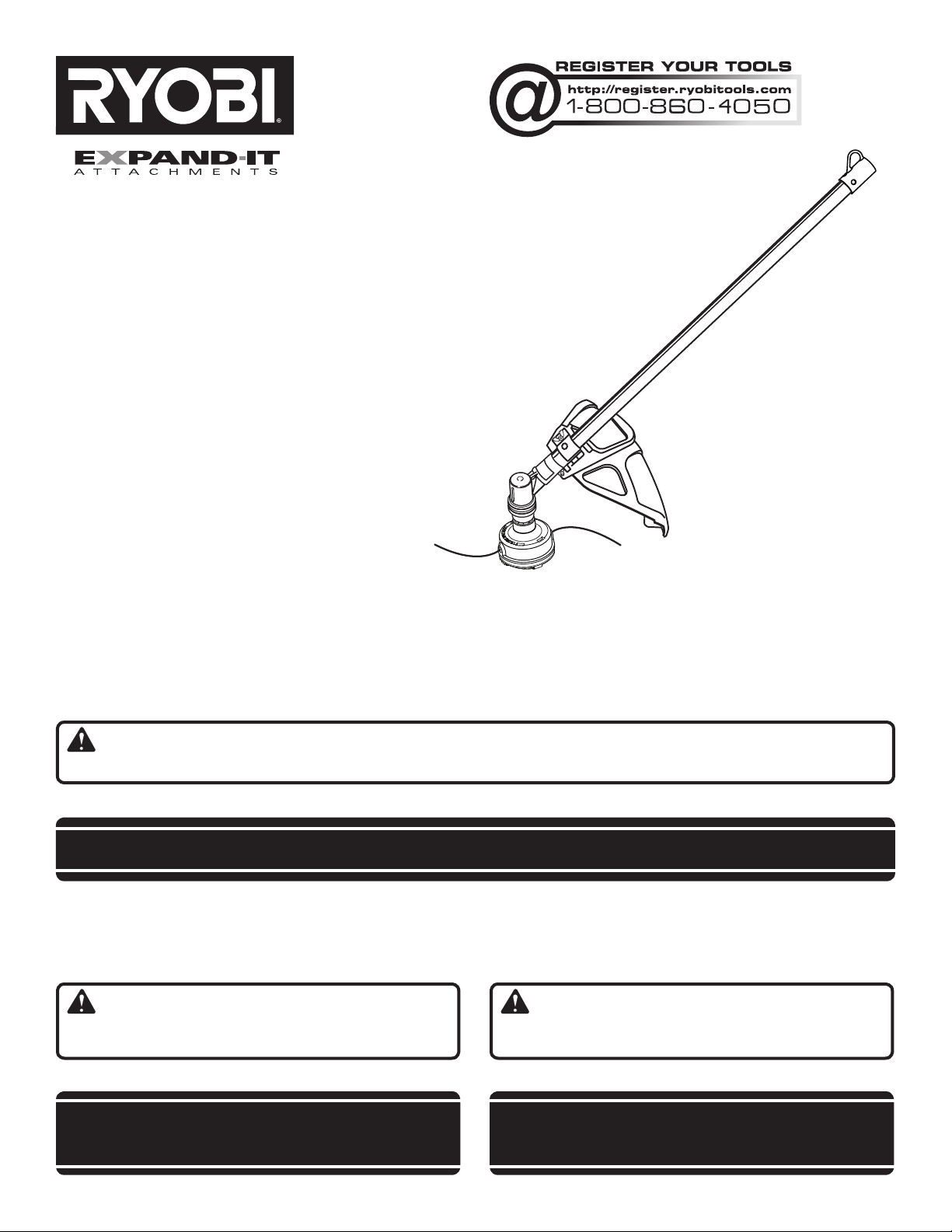
STRAIGHT SHAFT
TRIMMER ATTACHMENT
ARBRE DROIT ACCESSOIRE
TAILLE-BORDURES
ACCESORIO PARA RECORTAR
DE EJE RECTO
RY15523
Your trimmer attachment has been engineered and manufactured to our high standard for dependability, ease of operation,
and operator safety. When properly cared for, it will give you years of rugged, trouble-free performance.
WARNING: To reduce the risk of injury, the user must read and understand the operator’s manual before using
this product.
Thank you for your purchase.
SAVE THIS MANUAL FOR FUTURE REFERENCE
L’accessoire taille-bordures a été conçue et fabriquée conformément
à nos strictes normes de fiabilité, simplicité d’emploi et sécurité
d’utilisation. Correctement entretenue, elle vous donnera des
années de fonctionnement robuste et sans problème.
AVERTISSEMENT : Pour réduire les risques de
blessures, l’utilisateur doit lire et veiller à bien comprendre le
manuel d’utilisation avant d’employer ce produit.
Merci de votre achat.
CONSERVER CE MANUEL POUR
FUTURE RÉFÉRENCE
Su nuevo accesorio para recortar ha sido diseñada y fabricada
de conformidad con las estrictas normas para brindar fiabilidad,
facilidad de uso y seguridad para el operador. Con el debido cuidado,
le brindará muchos años de sólido y eficiente funcionamiento.
ADVERTENCIA: Para reducir el riesgo de lesiones,
el usuario debe leer y comprender el manual del operador antes
de usar este producto.
Le agradecemos su compra.
GUARDE ESTE MANUAL PARA
FUTURAS CONSULTAS
Page 2
See this fold-out section for all of the figures referenced in the operator’s manual.
Consulter l’encart à volets afin d’examiner toutes les figures mentionnées dans le manuel d’utilisation.
Consulte esta sección desplegable para ver todas las figuras a las que se hace referencia en el manual del operador.
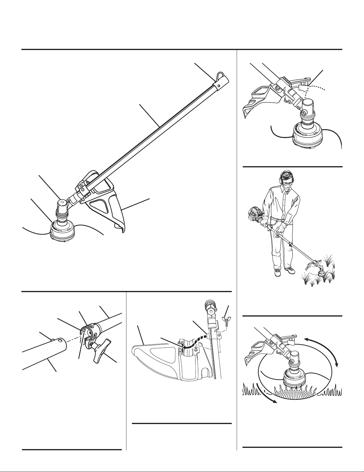
Fig. 1
D
A
B
A - Line trimming cut-off blade (lame de
sectionnement de ligne, cuchilla de corte)
C
Fig.5
E
A
Fig. 4
A - Hanger cap (capuchon de suspension, tapa
de suspensión)
B - Trimmer shaft (arbre du taille-bordures, eje
de la recortadora)
C - Gear head (carter d’engrenages, cabezal de
engranajes)
Fig. 2
A
B
C
D
F
E
A - Power head shaft (arbre moteur, cabezal
motor eje)
B - Coupler (coupleur, acoplador)
C - Guide recess (renfoncement du guide,
hueco guía)
D - Button (bouton, botón)
E - Attachment shaft (arbre de l’accessoire, eje
del accesorio)
F - Positioning hole (trou de positionnement,
orificio de posicionamiento)
G - Knob (bouton, perilla)
D - String head (tête à ligne de coupe, cabezal
del hilo)
E - Grass deflector (déflecteur d’herbe,
deflector de pasto)
Fig. 3
D
C
G
A - Wing screw (vis à oreilles, tornillo de
mariposa)
B - Tab (languette, orejeta)
C - Slot (fente, ranura)
D - Grass deflector (déflecteur d’herbe,
deflector de pasto)
B
PROPER OPERATING POSITION / BONNE
A
POSITION DE TRAVAIL / POSICIÓN
CORRECTA PARA EL MANEJO DE LA
HERRAMIENTA
Fig. 6
B
A - Dangerous cutting area (zone de coupe
dangereuse, área peligrosa de corte)
B - Direction of rotation (sens de rotation,
sentido de rotación)
C - Best cutting area (zone d’efficacité
maximum, mejor área de corte)
C
A
ii
Page 3
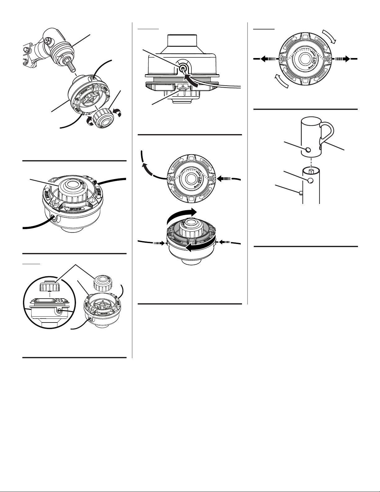
Fig. 7
A
Fig. 10
Fig. 12
C
B
A - Drive shaft (arbre moteur, eje de impulsión)
B - string head (tête de coupe, cabezal del hilo)
C - Spool retainer (retenue de bobine, retén del
carrete)
Fig. 8
A
A - Spool retainer (retenue de bobine, retén del
carrete)
A
B
A - Eyelet (oeillet, ojillo)
B - Arrow on spool (flèche sur la bobine, flecha
en el carrete)
Fig. 11
A
A
A - Pull strings (tirer vers l’extérieur, tira del
hilo)
Fig. 13
A
D
B
C
A - Hole (trou, orificio)
B - Secondary hole (trou secondaire, orificio
secundario)
C - Button (bouton, botón)
D - Hanger cap (capuchon de suspension, tapa
de suspensión)
Fig. 9
A
B
A - Spool retainer (retenue de bobine, retén del
carrete)
B - Spool (bobine, carrete)
A - Pull strings (tirer vers l’extérieur, tira del
hilo)
B - Rotate the spool counterclock wise (tourner
le bobine dans le sens antihoraire, gire a la
izquierda el carrete)
iii
Page 4

TABLE OF CONTENTS
TABLE DES MATIÈRES / ÍNDICE DE CONTENIDO
Introduction ......................................................................................................................................................................2
Introduction / Introducción
General Safety Rules ........................................................................................................................................................ 3
Règles de sécurité générales / Reglas de seguridad generales
Specific Safety Rules ........................................................................................................................................................ 3
Règles de sécurité particulières / Reglas de seguridad específicas
Symbols ............................................................................................................................................................................ 4
Symboles / Símbolos
Features ............................................................................................................................................................................5
Caractéristiques / Características
Assembly .......................................................................................................................................................................5-6
Assemblage / Armado
Operation .......................................................................................................................................................................6-7
Utilisation / Funcionamiento
Maintenance ..................................................................................................................................................................8-9
Entretien / Mantenimiento
Warranty .........................................................................................................................................................................10
Garantie / Garantía
Exploded View and Parts List .................................................................................................................................... 11-12
Vue éclatée et liste des pièces / Vista desarrollada y lista de piezas
Parts Ordering and Service ...............................................................................................................................Back Page
Commande de pièces et réparation / Pedidos de piezas y servicio ......................................................... Page arrière / Pág. posterior
INTRODUCTION
INTRODUCTION / INTRODUCCIÓN
This product has many features for making its use more pleasant and enjoyable. Safety, performance, and dependability
have been given top priority in the design of this product making it easy to maintain and operate.
* * *
Ce produit offre de nombreuses fonctions destinées à rendre son utilisation plus plaisante et satisfaisante. Lors de la
conception de ce produit, l’accent a été mis sur la sécurité, les performances et la fiabilité, afin d’en faire un outil facile à
utiliser et à entretenir.
* * *
Este producto ofrece numerosas características para hacer más agradable y placentero su uso. En el diseño de este producto
se ha conferido prioridad a la seguridad, el desempeño y la fiabilidad, por lo cual se facilita su manejo y mantenimiento.
2
Page 5

GENERAL SAFETY RULES
WARNING:
Read and understand all instructions. Failure to follow
all instructions listed below may result in electric shock,
fire, and/or serious personal injury.
SAVE THESE INSTRUCTIONS
Read these instructions and the instructions for the power
head thoroughly before using the straight shaft trimmer
attachment.
Know the tool. Read and understand the operator’s
manual and observe the warnings and instruction labels
affixed to the tool.
Do not allow children or untrained individuals to use this
unit.
Always wear eye protection with side shields marked to
comply with ANSI Z87.1.
Wear heavy long pants, boots, and gloves. Do not wear
loose fitting clothing, short pants, jewelry of any kind, or
go barefoot.
Secure long hair so it is above shoulder level to prevent
entanglement in any moving parts.
Keep all bystanders, children, and pets at least 50 ft.
away. Bystanders should be encouraged to wear eye
protection.
Stay alert, watch what you are doing, and use common
sense when operating a power tool. Do not use tool while
tired or under the influence of drugs, alcohol, or medica-
tion. A moment of inattention while operating power tools
may result in serious personal injury.
Do not operate in poor lighting.
Do not overreach. Keep proper footing and balance at all
times. Proper footing and balance enables better control
of the tool in unexpected situations.
Keep all parts of your body away from any moving part.
Do not touch areas around the muffler or cylinder of the
power head. These parts get hot from operation. Failure
to heed this warning could result in possible serious
personal injury.
Always stop the engine and remove the spark plug wire
before making any adjustments or repairs except for
carburetor adjustments.
Inspect unit before each use for loose fasteners and dam-
aged or missing parts. Correct before using the trimmer
attachment. Failure to do so can cause serious injury.
Use only original manufacturer’s replacement parts.
Failure to do so may cause poor performance, possible
injury, and will void your warranty.
Do not, under any circumstance, use any attachment or
accessory on this product, which was not provided with
the product, or identified as appropriate for use with this
product in the operator’s manual.
Avoid dangerous environments. Do not use the attach-
ment in damp or wet locations. Do not use in rain.
Use the right attachment. Do not use attachment for any
job except that for which it is intended.
SPECIFIC SAFETY RULES
Replace string head if cracked, chipped, or damaged
in any way. Be sure the string head is properly installed
and securely fastened. Failure to do so can cause serious
injury.
Make sure all deflectors and handles are properly and
securely attached.
Use only flexible, non-metallic line recommended by the
manufacturer. Never use wire, wire rope, or flail blades,
which can break off and become dangerous projectiles.
Never operate string trimmer without the grass deflector
in place and in good condition.
Maintain a firm grip on both handles while trimming.
3 — English
Keep string head below waist level. Never cut with
the string head located over 30 in. or more above the
ground.
Clear the work area before each use. Remove all objects
such as rocks, broken glass, nails, wire, or string which
can be thrown or become entangled in the cutting line.
To prevent electrical shock or serious personal injury, do
not use this product with any electric power head.
Save these instructions. Refer to them frequently and
use them to instruct others who may use this tool.
If you loan someone this tool, loan them these instructions also to prevent misuse of the product and
possible injury.
NOTE: SEE YOUR POWER HEAD OPERATOR’S MANUAL
FOR ADDITIONAL SPECIFIC SAFETY RULES.
Page 6
SYMBOLS
The following signal words and meanings are intended to explain the levels of risk associated with this product.
SYMBOL SIGNAL MEANING
DANGER:
WARNING:
CAUTION:
CAUTION:
Some of the following symbols may be used on this product. Please study them and learn their meaning. Proper
interpretation of these symbols will allow you to operate the product better and safer.
Indicates an imminently hazardous situation, which, if not avoided, will result
in death or serious injury.
Indicates a potentially hazardous situation, which, if not avoided, could result
in death or serious injury.
Indicates a potentially hazardous situation, which, if not avoided, may result in
minor or moderate injury.
(Without Safety Alert Symbol) Indicates a situation that may result in property
damage.
SYMBOL NAME EXPLANATION
Safety Alert Symbol Indicates a potential personal injury hazard.
Read the Operator’s Manual
To reduce the risk of injury, user must read and understand
operator’s manual before using this product.
Always wear eye protection with side shields marked to
Eye and Hearing Protection
Keep Bystanders Away Keep all bystanders at least 50 ft. away.
Ricochet
No Blade
comply with ANSI Z87.1, along with hearing protection when
operating this equipment.
Thrown objects can ricochet and result in personal injury or
property damage.
Do not install or use any type of blade on a product
displaying this symbol.
4 — English
Page 7
FEATURES
PRODUCT SPECIFICATIONS
Weight ................................................................... 3.25 lbs.
Line Cutting Width ...................................................... 18 in.
KNOW YOUR STRING TRIMMER
ATTACHMENT
See Figure 1.
The safe use of this product requires an understanding of
the information on the product and in this operator’s manual
as well as a knowledge of the project you are attempting.
ASSEMBLY
UNPACKING
This product requires assembly.
Carefully remove the items from the box. Make sure that
all items listed in the packing list are included.
WARNING:
Do not use this product if any parts on the packing list
are already assembled to your product when you unpack
it. Parts on this list are not assembled to the product by
the manufacturer and require customer installation. Use
of a product that may have been improperly assembled
could result in serious personal injury.
Inspect the unit carefully to make sure no damage oc-
curred during shipping.
Do not discard the packing material until you have
carefully inspected and satisfactorily operated the
product.
If any parts are damaged or missing, please call
1-800-860-4050 for assistance.
PACKING LIST
Ryobi® Expand-it™ Straight Shaft Trimmer Attachment
Grass Deflector
Operator’s Manual
Line Diameter
Gas Power Head ................. .080 in. to .095 in. max.
Electric Power Head .................................. .080 max.
Before use of this product, familiarize yourself with all operating features and safety rules.
GRASS DEFLECTOR
The trimmer includes a grass deflector that helps protect
you from flying debris.
WARNING:
If any parts are damaged or missing do not operate this
product until the parts are replaced. Use of this product
with damaged or missing parts could result in serious
personal injury.
WARNING:
Do not attempt to modify this product or create accessories not recommended for use with this product. Any
such alteration or modification is misuse and could result
in a hazardous condition leading to possible serious
personal injury.
WARNING:
Do not connect to power head until assembly is complete.
Failure to comply could result in accidental starting and
possible serious personal injury.
JOINING THE POWER HEAD TO THE
STRAIGHT SHAFT TRIMMER ATTACHMENT
See Figure 2.
Never attach or adjust any attachment while power head
is running. Failure to stop the engine or motor may cause
serious personal injury.
5 — English
WARNING:
Page 8

ASSEMBLY
The straight shaft trimmer attachment connects to the power
head by means of a coupler device.
Remove the hanger cap from the attachment shaft.
Loosen the knob on the coupler of the power head shaft.
Push in the button located on the straight shaft trimmer
attachment. Align the button with the guide recess on the
power head coupler and slide the two shafts together.
Rotate attachment shaft until button locks into the positioning hole.
NOTE: If the buttons do not release completely in the
positioning holes, the shafts are not locked into place.
Slightly rotate from side to side until the button is locked
into place.
Tighten the knob securely.
WARNING:
Be certain the knob is fully tightened before operating
equipment. Check it periodically for tightness during use
to avoid serious injury.
ATTACHING THE GRASS DEFLECTOR
See Figure 3.
NOTE: Install the grass deflector before the attachment is
connected to the power head.
Remove the wing screw from the grass deflector.
Insert the tab on the mounting bracket in the slot on the
grass deflector.
Align the screw hole in the mounting bracket with the
screw hole in the grass deflector.
Insert the wing screw through the mounting bracket and
into the grass deflector.
Tighten the screw securely.
REMOVING THE ATTACHMENT FROM THE
POWER HEAD
For removing or changing the attachment:
Stop the engine or motor.
Loosen the knob.
Push in the button and twist the shafts to remove and
separate ends.
OPERATION
WARNING:
Do not allow familiarity with this product to make you
careless. Remember that a careless fraction of a second is
sufficient to inflict serious injury.
WARNING:
Always wear eye protection with side shields marked to
comply with ANSI Z87.1. Failure to do so could result in
objects being thrown into your eyes, resulting in possible
serious injury.
WARNING:
Do not use any attachments or accessories not
recommended by the manufacturer of this product. The
use of attachments or accessories not recommended
can result in serious personal injury.
APPLICATIONS
You may use this product for the purpose listed below:
Trimming grass and weeds from around porches, fences,
and decks
LINE TRIMMING CUT-OFF BLADE
See Figure 4.
The trimmer is equipped with a line trimming cut-off blade
on the grass deflector. Replace the line whenever you hear
the engine running faster than normal, or when trimming
efficiency diminishes. This will maintain best performance.
OPERATING THE TRIMMER
See Figure 5.
WARNING:
Engine housing on gas power heads may become hot
during trimmer operation. Do not rest or place your arm,
hand, or any body part against the engine housing during trimmer operation. Only hold the trimmer as shown
in Figure 4 with all body parts clear of engine housing.
Extended contact with the engine housing may result in
burns or other injuries.
6 — English
Page 9
OPERATION
WARNING:
Always position the unit on the operator’s right side. The
use of the unit on the operator’s left side will expose
the user to hot surfaces and can result in possible burn
injury.
WARNING:
To avoid burns from hot surfaces, never operate unit with
the bottom of the engine above waist level.
Hold the trimmer with your right hand on the rear handle
and your left hand on the front handle. Keep a firm grip with
both hands while in operation. Trimmer should be held at a
comfortable position with the rear handle about hip height.
CUTTING TIPS
See Figures 5 - 6.
Avoid hot surfaces by always keeping the tool away from
your body. (Proper operating position shown in figure 5.)
Keep the trimmer tilted toward the area being cut; this is
the best cutting area.
The trimmer cuts when passing the unit from right to left.
This will avoid throwing debris at the operator. Avoid cutting in the dangerous area shown in figure 6.
Use the tip of line to do the cutting; do not force string
head into uncut grass.
Wire and picket fences cause extra line wear and break-
age. Stone and brick walls, curbs, and wood may wear
line rapidly.
Avoid trees and shrubs. Tree bark, wood moldings, siding,
and fence posts can easily be damaged by the line.
Always operate trimmer at full throttle for gas power heads
or with the switch trigger fully pressed for electric power
heads. Cut tall grass from the top down. This will prevent
grass from wrapping around the shaft housing and string
head which may cause damage from overheating. If grass
becomes wrapped around the string head, STOP THE ENGINE or MOTOR, disconnect the spark plug wire for gas
power heads or disconnect the plug from the power source
for electric power heads, and remove the grass. Prolonged
cutting at partial throttle will result in lubricant dripping from
the muffler.
WARNING:
Always hold the string trimmer away from the body keeping clearance between the body and the product. Any
contact with the housing or string trimmer cutting head
can result in burns and/or other serious personal injury.
ADVANCING LINE USING THE REEL-EASY™
TAP ADVANCE SYSTEM
Line advance is controlled by tapping the string head’s
spool retainer on grass while running engine at full throttle for gas power heads or with the switch trigger fully
pressed for electric power heads.
Run engine at full throttle for gas power heads or with the
switch trigger fully pressed for electric power heads.
Tap string head on ground to advance line. Line advances
each time the head is tapped.
Several taps may be required until line strikes the cut off
blade.
Resume trimming.
NOTE: If the line is worn too short you may not be able
to advance the line by tapping it on the ground. If so,
STOP THE ENGINE or MOTOR, disconnect the spark plug
wire for gas power heads or disconnect the plug from
the power source for electric power heads, and manually
advance the line.
ADVANCING THE LINE MANUALLY
Stop the unit. Push the spool retainer down while pulling
on line(s) to manually advance the line.
7 — English
Page 10
MAINTENANCE
WARNING:
When servicing, use only identical replacement parts.
Use of any other parts may create a hazard or cause
product damage.
WARNING:
Always wear eye protection with side shields marked to
comply with ANSI Z87.1. Failure to do so could result in
objects being thrown into your eyes, resulting in possible
serious injury.
Use only .095 in. trimmer line.
Stop the unit and disconnect the spark plug wire. Hold
the string head and unscrew the spool retainer.
Remove the empty spool from the string head.
NOTE: It is not necessary to remove the string head
housing from the drive shaft.
Insert the new spool into the string head.
NOTE: Make sure the arrows on the spool are aligned
with the eyelets in the string head housing. Push down
and hold the spool and housing together while completing
the installation.
Reinstall the spool retainer to secure.
Install line as described in LINE REPLACEMENT.
WARNING:
Before inspecting, cleaning, or servicing the machine,
shut off engine, wait for all moving parts to stop, and
disconnect spark plug wire and move it away from spark
plug. Failure to follow these instructions can result in
serious personal injury or property damage.
GENERAL MAINTENANCE
Avoid using solvents when cleaning plastic parts. Most
plastics are susceptible to damage from various types of
commercial solvents and may be damaged by their use. Use
clean cloths to remove dirt, dust, oil, grease, etc.
WARNING:
Do not at any time let brake fluids, gasoline, petroleumbased products, penetrating oils, etc., come in contact
with plastic parts. Chemicals can damage, weaken or destroy plastic which may result in serious personal injury.
You can often make adjustments and repairs described
here. For other repairs, have the trimmer serviced by an
authorized service dealer.
SPOOL REPLACEMENT
REEL-EASY™ TAP ADVANCE SYSTEM
See Figures 7 - 10.
If replacing line only, refer to LINE REPLACEMENT later in
this manual.
LINE REPLACEMENT
See Figure 11 - 12.
Stop the unit
Rotate the spool clockwise as necessary to align the
arrows on the spool with the eyelets in the string head
housing.
Cut one piece of trimmer line 10 ft. long. Insert the line
into the eyelet on the string trimmer housing. Push until
the end of the line comes out the other side of the string
head. Pull the line from the other side until equal amounts
of line appear on both sides of the spool.
Rotate the spool clockwise to wind the line on the spool
until approximately 6 in. of line is showing on each side.
Push the spool retainer down while pulling on line(s) to
manually advance the line and to check for proper assembly of the string head.
ATTACHING THE STORAGE HANGER
See Figure 13.
There are two ways to hang the attachment for storage.
To use the hanger cap, push in the button and place the hang-
er cap over the end of the attachment shaft. Slightly rotate
the cap from side to side until the button locks into place.
The secondary hole in the attachment shaft can be used
for hanging purposes as well.
STORING THE ATTACHMENT
Store the attachment in a well-ventilated place that is
inaccessible to children.
Keep away from corrosive agents such as garden chemi-
cals and deicing salts.
8 — English
Page 11

MAINTENANCE
MAKE THE MOST OF YOUR PURCHASE!
Go to www.ryobitools.com and register your new tool on-line.
Your product has been fully tested prior to shipment
to ensure your complete satisfaction.
For any questions about operating or maintaining
your product, call the Ryobi Help Line!
To register your Ryobi product by regular mail, please print the following information on a 3 in. x 5 in. card or
standard postcard: your name, mailing address, phone numbers, email address, Ryobi product(s) purchased
with item number from package, and serial number for each product. Mail the card to: Techtronic Industries
North America, Inc., Attn. Ryobi Registration, 1428 Pearman Dairy Road, Anderson, SC 29625.To receive information on our company and products, please include the following statement on your registration card: “Send
me information on your products and company using the contact information I am providing with this product
registration.”
9 — English
Page 12

WARRANTY
LIMITED WARRANTY STATEMENT
Techtronic Industries North America, Inc., warrants to the
original retail purchaser that this RYOBI® brand outdoor
product is free from defect in material and workmanship
and agrees to repair or replace, at Techtronic Industries
North America, Inc.’s, discretion, any defective product
free of charge within these time periods from the date of
purchase.
Three years if the product is used for personal, family
or household use;
90 days, if used for any other purpose, such as
commercial or rental.
This warranty extends to the original retail purchaser
only and commences on the date of the original retail
purchase.
Any part of this product found in the reasonable judgment
of Techtronic Industries North America, Inc. to be defective
in material or workmanship will be repaired or replaced
without charge for parts and labor by an authorized service
center for RYOBI® brand outdoor products (Authorized
Ryobi Service Center).
The product, including any defective part, must be returned
to an authorized Ryobi service center within the warranty
period. The expense of delivering the product to the service
center for warranty work and the expense of returning it
back to the owner after repair or replacement will be paid
by the owner. Techtronic Industries North America, Inc.’s,
responsibility in respect to claims is limited to making the
required repairs or replacements and no claim of breach of
warranty shall be cause for cancellation or rescission of the
contract of sale of any RYOBI® brand outdoor product. Proof
of purchase will be required by the dealer to substantiate
any warranty claim. All warranty work must be performed
by an authorized service dealer.
This warranty is limited to ninety (90) days from the date
of original retail purchase for any RYOBI® brand outdoor
product that is used for rental or commercial purposes, or
any other income-producing purpose.
This warranty does not cover any product that has been
subject to misuse, neglect, negligence, or accident, or that
has been operated in any way contrary to the operating
instructions as specified in this operator’s manual. This
warranty does not apply to any damage to the product that
is the result of improper maintenance or to any product
that has been altered or modified. The warranty does not
extend to repairs made necessary by normal wear or by the
use of parts or accessories which are either incompatible
with the RYOBI® brand outdoor product or adversely affect
its operation, performance, or durability. In addition, this
warranty does not cover:
A. Tune-ups – Spark Plugs, Carburetor, Carburetor
Adjustments, Ignition, Filters
B. Wear items – Bump Knobs, Outer Spools, Cutting
Lines, Inner Reels, Starter Pulleys, Starter Ropes, Drive
Belts, Tines, Felt Washers, Hitch Pins, Mulching Blades,
Blower Fans, Blower and Vacuum Tubes, Vacuum Bag
and Straps, Guide Bars, Saw Chains
Techtronic Industries North America, Inc., reserves the
right to change or improve the design of any RYOBI® brand
outdoor product without assuming any obligation to modify
any product previously manufactured.
ALL IMPLIED WARRANTIES ARE LIMITED IN DURATION
TO THE STATED WARRANTY PERIOD. ACCORDINGLY,
ANY SUCH IMPLIED WARRANTIES INCLUDING
MERCHANTABILITY, FITNESS FOR A PARTICULAR
PURPOSE, OR OTHERWISE, ARE DISCLAIMED
IN THEIR ENTIRETY AFTER THE EXPIRATION OF
THE APPROPRIATE THREE-YEAR OR NINETY-DAY
WARRANTY PERIOD. TECHTRONIC INDUSTRIES
NORTH AMERICA, INC.’S, OBLIGATION UNDER THIS
WARRANTY IS STRICTLY AND EXCLUSIVELY LIMITED TO
THE REPAIR OR REPLACEMENT OF DEFECTIVE PARTS
AND TECHTRONIC INDUSTRIES NORTH AMERICA,
INC., DOES NOT ASSUME OR AUTHORIZE ANYONE
TO ASSUME FOR THEM ANY OTHER OBLIGATION.
SOME STATES DO NOT ALLOW LIMITATIONS ON HOW
LONG AN IMPLIED WARRANTY LASTS, SO THE ABOVE
LIMITATION MAY NOT APPLY TO YOU. TECHTRONIC
INDUSTRIES NORTH AMERICA, INC., ASSUMES NO
RESPONSIBILITY FOR INCIDENTAL, CONSEQUENTIAL,
OR OTHER DAMAGES INCLUDING, BUT NOT LIMITED
TO, EXPENSE OF RETURNING THE PRODUCT TO AN
AUTHORIZED RYOBI SERVICE CENTER AND EXPENSE
OF DELIVERING IT BACK TO THE OWNER, MECHANIC’S
TRAVEL TIME, TELEPHONE OR TELEGRAM CHARGES,
RENTAL OF A LIKE PRODUCT DURING THE TIME
WARRANTY SERVICE IS BEING PERFORMED, TRAVEL,
LOSS OR DAMAGE TO PERSONAL PROPERTY, LOSS
OF REVENUE, LOSS OF USE OF THE PRODUCT, LOSS
OF TIME, OR INCONVENIENCE. SOME STATES DO NOT
ALLOW THE EXCLUSION OR LIMITATION OF INCIDENTAL
OR CONSEQUENTIAL DAMAGES, SO THE ABOVE
LIMITATION OR EXCLUSION MAY NOT APPLY TO YOU.
This warranty gives you specific legal rights, and you may
also have other rights which vary from state to state.
This warranty applies to all RYOBI® brand outdoor products
manufactured by or for Techtronic Industries North America,
Inc., and sold in the United States and Canada.
To locate your nearest Authorized Ryobi Service Center,
dial 1-800-860-4050.
10 — English
Page 13

EXPLODED VIEW AND PARTS LIST
VUE ÉCLATÉE ET LISTE DES PIÈCES
VISTA DESARROLLADA Y LISTA DE PIEZAS
1
2
4
8
5
7
11
3
6
12
13
14
10
9
11
15
16
17
18
Page 14

EXPLODED VIEW AND PARTS LIST
VUE ÉCLATÉE ET LISTE DES PIÈCES
VISTA DESARROLLADA Y LISTA DE PIEZAS
KEY NO.
Pièce
Num.
Núm. Ref.
PART NO.
Num. Réf.
Núm. Pieza
DESCRIPTION
1 940726013 Expand-it Label
2 940230132 Warning Decal
3 308035011 Straight Shaft Assembly
4 660736001 * Screw (10-24 x 5/8 in.)
5 638125001 Clamp
6 518367001 Spacer
7 660642001 Screw (1/4-20 x 1-1/4 in.)
8 308210002 Gear Head
9 678011002 Flanged Washer
10 678019002 Arbor
DESCRIPTION DESCRIPCIÓN
Autocollant Expand-it Etiqueta Expand-it
Autocollant d’avertissement Calcomanía de advertencia
Arbre droit Conjunto del eje recto
Vis (10-24 x 5/8 po) Tornillo (10-24 x 5/8 pulg.)
Bride Abrazadera
Pièce d’écartement Separador
Vis (1/4-20 x 1-1/4 po) Tornillo (1/4-20 x 1-1/4 pulg.)
Carter d’engrenages Cabezal de engranajes
Rondelle à épaulement Arandela de brida
Axe Árbol
QTY.
Qté.
Cant.
1
1
1
1
1
1
1
1
1
1
11 660886001 Wing Screw (1/4-20 x 1-1/4 in.)
12 308473001
Grass Deflector Assembly
(Incl. Key No. 11)
13 518019002 Hanger Cap
14 310643001 Bump Feed String Head
15 678022001 Spring
16 310412001 Bump Feed Spool
17 308042003 Spool Retainer
18 309562001
Bump Feed String Head Assembly (Incl. Key No. 14-16)
Vis à oreilles (1/4-20 x 1-1/4 po)
Déflecteur d’herbe (incl. pièce
no. 11)
Capuchon de suspension Tapa de suspensión
Tête de coupe à alimentation par
choc
Ressort Resorte
Bobine à alimentation par choc Carrete con alimentación por golpe
Rretenue de bobine Retén del carrete
Ensemble tête de coupe à avance
de fil par choc (incl. pièces no. 14
à 16)
* STANDARD HARDWARE ITEM — MAY BE PURCHASED LOCALLY
* ARTICLE DE QUINCAILLERIE STANDARD — EN VENTE DANS LES MAGASINS LOCAUX
* ARTÍCULO ESTÁNDAR DE FERRETERÍA — PUEDE ADQUIRIRSE EN LA LOCALIDAD
Tornillo de mariposa (1/4-20 x
1-1/4 pulg.)
Conjunto del deflector de pasto
(incl. pzas núm. ref. 11)
Cabezal del hilo con alimentación
por golpe
Conjunto del cabezal del hilo con
alimentación por golpe (incl. pzas.
núms. ref. 14 a 17)
1
1
1
1
1
1
1
1
12
Page 15

NOTES / NOTES / NOTAS
13
Page 16

NOTES / NOTES / NOTAS
14
Page 17

NOTES / NOTES / NOTAS
15
Page 18

RÈGLES DE SÉCURITÉ GÉNÉRALES
AVERTISSEMENT :
Lire et veiller à bien comprendre toutes les
instructions. Le non-respect de toutes les instructions
ci-dessous peut entraîner un choc électrique, un
incendie et/ou des blessures graves.
CONSERVER CES INSTRUCTIONS
Lire attentivement ces instructions et celles du moteur
avant d’utiliser cet accessoire.
Apprendre à connaître l’outil. Lire et veiller à bien
comprendre le manuel de l’opérateur et observer les
avertissements et les instructions des autocollants
apposés sur l’outil.
Ne pas laisser des enfants ou des personnes n’ayant pas
reçu une formation adéquate utiliser cet outil.
Toujours porter une protection oculaire avec écrans
latéraux certifiée conforme à la norme ANSI Z87.1.
Porter des pantalons longs, des chaussures de travail et des
gants épais. Ne pas porter de vêtements amples, shorts,
bijoux quels qu’ils soient et ne pas travailler pieds nus.
Attacher les cheveux longs pour les maintenir au-dessus
des épaules, afin qu’ils ne se prennent pas dans les
pièces en mouvement.
Garder les badauds, enfants et animaux domestiques à
une distance minimum de 15 m (50 pi). Recommander aux
personnes présentes de porter une protection oculaire.
Rester attentif, prêter attention au travail, et faire preuve
de bon sens lors de l’utilisation de tout outil électrique. Ne
pas utiliser cet outil en état de fatigue ou sous l’influence
d’alcool, de drogues ou de médicaments. Un moment
d’inattention pendant l’utilisation d’un outil électrique
peut entraîner des blessures graves.
Ne pas travailler sous un éclairage insuffisant.
Ne pas travailler hors de portée. Toujours se tenir bien
campé et en équilibre. Des pieds bien campés et un bon
équilibre permettent de mieux contrôler l’outil en cas de
situation imprévue.
Garder toutes les parties du corps à l’écart des pièces
en mouvement.
Ne pas toucher les zones autour de l’échappement ou du
cylindre du moteur. Ces pièces deviennent très chaudes
en cours de fonctionnement. Ne pas prendre cette
précaution pourrait entraîner des blessures graves.
Toujours arrêter le moteur et débrancher le fil de la bougie
avant d’effectuer tout entretien ou réglage, à l’exception
des réglages du carburateur.
Inspecter l’appareil avant chaque utilisation pour s’assurer
qu’il n’y a pas de fixations desserrées ou de pièces
endommagées ou manquantes. Effectuer les corrections
requises avant d’utiliser l’accessoire taille-bordures. Ne
pas prendre cette précaution peut entraîner des risques
de blessures graves.
Utiliser exclusivement des pièces de rechange
d’origine. Toute dérogation peut entraîner un mauvais
fonctionnement, des blessures graves et l’annulation de
la garantie.
N’utiliser en aucun cas un accessoire non fourni avec le
produit, ou non indiqué comme pouvant être utilisé sur
l’outil dans le manuel d’utilisation.
Éviter les environnements dangereux. Ne pas utiliser
l’accessoire dans des endroits humides ou mouillés. Ne
pas utiliser sous la pluie.
Utiliser l’accessoire approprié. Ne pas utiliser l’accessoire
dans une application pour laquelle il n’a pas été prévu.
RÈGLES DE SÉCURITÉ PARTICULIÈRES
Si la tête de coupe est fendue, brisée ou endommagée
de quelque façon que ce soit, la remplacer. S’assurer que
la tête de coupe est correctement installée et solidement
assujettie. Ne pas prendre cette précaution peut entraîner
des risques de blessures graves.
S’assurer que tous les déflecteurs et toutes les poignées
sont correctement installés et solidement fixés.
N’utiliser que le fil flexible et non métallique recommandé
par le fabricant. Ne jamais utiliser un fil métallique, un
câble ou des lames de fléau susceptibles de devenir des
projectiles dangereux.
Ne jamais utiliser le taille-bordures si le déflecteur d’herbe
n’est pas en place et en bon état.
Tenir fermement les deux poignées pendant le travail.
Tenir la tête de coupe au-dessous du niveau de la taille.
Ne jamais couper en tenant la tête de coupe à plus de
76 centimètres (30 po) du sol.
3 — Français
Déblayer la zone de travail avant chaque utilisation. La
débarrasser de tous les objets tels que cailloux, verre
brisé, clous, fils métalliques, cordes, etc. risquant d’être
projetés ou de se prendre dans la ligne de coupe.
Pour éviter les risques de choc électrique ou de blessures
graves, ne pas utiliser ce produit avec un bloc moteur à
alimentation secteur.
Conserver ces instructions. Les consulter fréquemment
et les utiliser pour instruire les autres utilisateurs
éventuels. Si cet outil est prêté, il doit être accompagné
de ces instructions, afin d’éviter un usage incorrect et
d’éventuelles blessures.
NOTE : CONSULTEZ LE MANUEL D’UTILISATION DE BLOC
MOTEUR POUR DE TÊTE POUR DES SUPPLEMENTAIRE
RÈGLES DE SÉCURITÉ PARTICULIÈRES.
Page 19

SYMBOLES
Les termes de mise en garde suivants et leur signification ont pour but d’expliquer le degré de risques associé à
l’utilisation de ce produit.
SYMBOLE SIGNAL SIGNIFICATION
DANGER :
AVERTISSEMENT :
ATTENTION :
ATTENTION :
Certains des symboles ci-dessous peuvent être présents sur la produit. Veiller à les étudier et à apprendre leur
signification. Une interprétation correcte de ces symboles permettra d’utiliser la produit plus efficacement et de
réduire les risques.
SYMBOLE NOM EXPLICATION
Symbole d’alerte de sécurité Indique un risque de blessure potentiel.
Lire le manuel d’utilisation
Indique une situation extrêmement dangereuse qui, si elle n’est pas évitée,
aura pour conséquences des blessures graves ou mortelles.
Indique une situation potentiellement dangereuse qui, si elle n’est pas évitée,
pourrait entraîner des blessures graves ou mortelles.
Indique une situation potentiellement dangereuse qui, si elle n’est pas évitée,
pourraît entraîner des blessures légères ou de gravité modérée.
(Sans symbole d’alerte de sécurité) Indique une situation pouvant entraîner
des dommages matériels.
Pour réduire les risques de blessures, l’utilisateur doit lire
et veiller à bien comprendre le manuel d’utilisation avant
d’utiliser ce produit.
Protection oculaire et auditive
Ne laisser personne s’approcher
Ricochet
Ne pas utiliser de lame
Toujours porter une protection oculaire avec écrans latéraux
certifiée conforme à la norme ANSI Z87.1. ainsi qu’un
protection auditive.
Ne jamais laisser quiconque se tenir à moins de 15 m
(50 pi) de l’outil.
Ne pas utiliser le coupe-bourdures sans le protecteur. Rester
éloigné de la tête de coupe rotative.
Ne jamais utiliser une lame quelconque sur un outil portant
ce symbole.
4 — Français
Page 20

CARACTÉRISTIQUES
FICHE TECHNIQUE
Poids ....................................................................1,47 kg (3,25 lb)
Largeur de coupe de ligne.................................... 457 mm (18 po)
APPRENDRE À CONNAÎTRE L’ACCESSOIRE
TAILLE-BORDURES À ARBRE DROIT
Voir la figure 1.
La sécurité d’utilisation de ce produit exige la compréhension
des informations apposées sur le produit et contenues dans
ce manuel d’utilisation, ainsi que la connaissance du travail
ASSEMBLAGE
DÉBALLAGE
Ce produit nécessite l’assemblage
Avec précaution, sortir le produit et les accessoires de la
boîte. S’assurer que toutes les pièces figurant sur la liste de
contrôle sont incluses.
AVERTISSEMENT :
Ne pas utiliser le produit si, en le déballant, vous constatez
que des éléments figurant dans la liste d’expédition sont
déjà assemblés. Certaines pièces figurant sur cette liste
n’ont pas été assemblées par le fabricant et exigent une
installation. Le fait d’utiliser un produit qui a été assemblé
de façon inadéquate peut entraîner des blessures.
Examiner soigneusement le produit pour s’assurer que rien
n’a été brisé ou endommagé en cours de transport.
Ne pas jeter les matériaux d’emballage avant d’avoir
soigneusement examiné le produit et avoir vérifié qu’il
fonctionne correctement.
Si des pièces sont manquantes ou endommagées, appeler
le 1-800-860-4050.
Diamètre de coupe
Ensemble moteur à essence ................ 2,0 mm à 2,4 mm max.
(0,08 po à 0,095 po max.)
Ensemble moteur électrique .......................... 2,0 mm (0,08 po)
à exécuter. Avant d’utiliser ce produit, se familiariser avec
toutes ses fonctions et règles de sécurité.
DÉFLECTEUR D’HERBE
Le taille-bordures est équipé d’un déflecteur d’herbe qui
protège l’opérateur des débris projetés.
AVERTISSEMENT :
Ne pas essayer de modifier cet produit ou de créer des
accessoires non recommandés pour le produit. De telles
altérations ou modifications sont considérées comme un
usage abusif et peuvent créer des conditions dangereuses,
risquant d’entraîner des blessures graves.
AVERTISSEMENT :
Ne pas brancher sur le bloc-moteur avant d’avoir terminé
l’assemblage. Le non-respect de cet avertissement peut
causer un démarrage accidentel, entraînant des blessures
graves.
RACCORDEMENT DU BLOC-MOTEUR
À L’ACCESSOIRE TAILLE-BORDURES À
ARBRE DROIT
Voir la figure 2.
LISTE DE CONTRÔLE D’EXPÉDITION
Arbre droit accessoire Taille-bordures Ryobi® Expand-it
Déflecteur d’herbe
Fil pour taille-bordures précoupé
Manuel d’utilisation
™
AVERTISSEMENT :
Si des pièces manquent ou sont endommagées, ne pas
utiliser ce produit avant qu’elles aient été remplacées.
Le fait d’utiliser ce produit même s’il contient des pièces
endommagées ou s’il lui manque des pièces peut entraîner
des blessures graves.
AVERTISSEMENT :
Ne jamais installer ou ajuster un accessoire lorsque le
moteur tourne. Ceci pourrait causer des blessures graves.
L’accessoire taille-bordures à arbre droit se raccorde au blocmoteur à l’aide d’un dispositif de couplage.
Retirer l’anneau de suspension de l’arbre d’accessoire.
Desserrer le bouton du coupleur de l’arbre du bloc moteur.
Appuyer sur le bouton se trouvant sur l’accessoire de
taille-bordures. Aligner le bouton sur la rainure guide du
bloc moteur et emboîter les deux arbres. Tourner l’arbre
de l’accessoire jusqu’à ce que le bouton de verrouillage
s’engage dans le trou de positionnement.
5 — Français
Page 21

ASSEMBLAGE
NOTE : Si les boutons ne s’engagent pas complètement
dans les trous de positionnement, les arbres ne sont pas
solidement maintenus l’un dans l’autre. Tourner légèrement les
arbres dans les deux sens jusqu’à ce que le bouton s’engage
complètement.
Serrer le bouton fermement.
AVERTISSEMENT :
S’assurer que le bouton est bien serré avant d’utiliser l’outil.
Vérifier de temps à autre pour éviter le risque de blessures
graves.
INSTALLATION DU DÉFLECTEUR D’HERBE
Voir la figure 3.
NOTE : Installer le déflecteur d’herbe avant de fixer l’accessoire
sur l’ensemble moteur.
UTILISATION
AVERTISSEMENT :
Ne pas laisser la familiarité avec este produit faire oublier
la prudence. Ne pas oublier qu’une fraction de seconde
d’inattention peut entraîner des blessures graves.
AVERTISSEMENT :
Toujours porter une protection oculaire avec écrans latéraux
certifiée conforme à la norme ANSI Z87.1. Si cette précaution
n’est pas prise, des objets peuvent être projetés dans les
yeux et causer des lésions graves.
AVERTISSEMENT :
Ne pas utiliser d’outils ou accessoires non recommandés
par le fabricant pour cet produit. L’utilisation de pièces et
accessoires non recommandés peut entraîner des blessures
graves.
Retirer la vis à oreilles du déflecteur d’herbe.
Insérer la languette du support de montage dans la fente du
déflecteur d’herbe.
Aligner le trou de vis du support de montage sur le trou de
vis du déflecteur d’herbe.
Insérer la vis à oreilles dans le support et le déflecteur
d’herbe.
Serrer la vis fermement.
RETRAIT DE L’ACCESSOIRE DU BLOC
MOTEUR
Retrait ou remplacement de l’accessoire :
Arrêter le moteur ou du moteur électrique.
Desserrer le bouton.
Enfoncer le bouton et tourner les arbres pour retirer et
séparer les extrémités.
APPLICATIONS
Cet produit peut être utilisé pour les application ci-dessous :
Enlever aisément des mauvaises herbes et l’herbe du
pourtour des porches, barrières, et des terrasses
LAME DE SECTIONNEMENT DE LIGNE
Voir la figure 4.
Ce taille-bordures est équipé d’une lame de sectionnement
de ligne montée sur le déflecteur d’herbe. La ligne doit être
remplacer chaque fois que le moteur tourne à une vitesse
supérieure à la normale ou lorsque la coupe devient moins
efficace. Ceci maintient une efficacité maximum.
UTILISATION DU TAILLE-BORDURES
Voir la figure 5.
AVERTISSEMENT :
Le logement du moteur peut devenir chaud pendant
l’utilisation du taille bordures à fil (sur les ensembles
moteur à essence). Éviter de placer ou d’appuyer le bras,
la main ou toute autre partie du corps contre le logement
du moteur pendant l’utilisation du taille bordures. Tenir
l’outil uniquement dans la position illustrée à la figure 4
en s’assurant qu’aucune partie du corps ne se trouve à
proximité du logement du moteur. Un contact prolongé
avec le logement du moteur peut entraîner des brûlures ou
d’autres blessures.
6 — Français
Page 22

UTILISATION
AVERTISSEMENT :
Toujours tenir l’outil à sa droite. L’utilisation à gauche
exposerait l’utilisateur aux surfaces chaudes, créant ainsi
des risques de brûlures.
AVERTISSEMENT :
Pour éviter le contact avec les parties brûlantes, ne jamais
travailler avec le bas du moteur au-dessus du niveau de
la taille.
Tenir le taille-bordures avec la main droite sur la poignée
arrière et la main gauche sur la poignée avant. Garder
une prise ferme sur les deux poignées pendant le
fonctionnement. Le taille-bordures doit être tenu dans une
position confortable, la poignée arrière se trouvant à peu
près à hauteur de la taille.
Toujours utiliser le taille bordures à plein régime si celui-ci
est doté d’un ensemble moteur à essence, ou en appuyant
complètement sur la gâchette s’il est doté d’un ensemble
moteur électrique. Couper les herbes hautes de haut en
bas. Ceci empêchera l’herbe de s’enrouler sur le tube de
l’arbre moteur et la tête de coupe, ce qui pourrait causer
des dommages dus à une surchauffe. Si l’herbe s’enroule
sur la tête de coupe, ARRÊTER LE MOTEUR, débrancher
le fil de bougie s’il s’agit d’un ensemble moteur à essence
ou débrancher la fiche de la source d’alimentation s’il s’agit
d’un ensemble moteur électrique ,et enlever l’herbe.
AVERTISSEMENT :
Toujours tenir le taille-bordures à l’écart de soi en
maintenant une distance de sécurité entre le corps et
l’équipement. Tout contact avec le boîtier ou avec la tête
de coupe du taille-bordures peut causer des brûlures
et / ou d’autres blessures graves.
CONSEILS DE COUPE
Voir les figures 5 et 6.
Éviter les surfaces très chaudes en maintenant toujours
l’outil à l’écart du corps. (Position de travail correcte
illustrée à la figure 5.)
Pour une efficacité maximum, garder le taille-bordures
incliné vers la zone de coupe.
Pour couper avec le taille-bordures à arbre droit, utiliser
un mouvement de balayage de droite à gauche. Ceci évite
que les débris soient projetés en direction de l’opérateur.
Éviter de couper dans la zone dangereuse comme le
montre l’illustration à la figure 6.
Couper avec l’extrémité de la ligne; ne pas forcer la tête
de coupe dans l’herbe non coupée.
Les palissades en métal et en bois accélèrent l’usure de
la ligne et peuvent la faire casser. Les murs en pierre et
brique, trottoirs et pièces de bois peuvent user la ligne
rapidement.
Contourner les arbres et buissons. L’écorce des arbres,
les moulures en bois, le lambrissage et les piquets de
palissades peuvent être endommagés par la ligne.
AVANCE DE LA LIGNE DE COUPE AVEC LE
SYSTÈME À CHOC REEL-EASY
L’avance de la ligne est obtenue en tapant la tête de coupe
sur le gazon, tout en laissant fonctionner le moteur à plein
régime s’il s’agit d’un ensemble moteur à essence, ou en
appuyant complètement sur la gâchette s’il s’agit d’un
ensemble moteur électrique.
Faire fonctionner le moteur à plein régime s’il s’agit
d’un ensemble moteur à essence, ou en appuyant
complètement sur la gâchette s’il s’agit d’un ensemble
moteur électrique.
Taper la tête de coupe sur le sol pour faire avance la
ligne. La ligne avance chaque fois que la tête de coupe
est frappée sur le sol.
Plusieurs frappes peuvent être nécessaires pour que la
ligne parvienne à la lame coupe ligne
Continuer le travail.
NOTE: Si la ligne devient trop courte, il peut ne pas être
possible de la faire avancer en tapant la tête de coupe sur
le sol. Dans ce cas, ARRÊTER LE MOTEUR, débrancher le
fil de bougie s’il s’agit d’un ensemble moteur à essence ou
débrancher la fiche de la source d’alimentation s’il s’agit
d’un ensemble moteur électrique, et tirer la ligne à la main.
™
AVANCE MANUELLE DE LA LIGNE DE
COUPE
Lorsque le moteur est éteint et le fil de bougie a débranché,
appuyer sur la retenue de bobine et tirer sur la ligne pour
sortir la longueur désirée.
7 — Français
Page 23

ENTRETIEN
AVERTISSEMENT :
Utiliser exclusivement des pièces d’origine pour les
réparations. L’usage de toute autre pièce pourrait créer
une situation dangereuse ou endommager l’outil.
AVERTISSEMENT :
Toujours porter une protection oculaire avec écrans
latéraux certifiée conforme à la norme ANSI Z87.1. Si
cette précaution n’est pas prise, des objets peuvent être
projetés dans les yeux et causer des lésions graves.
Arrêter le moteur et débrancher le fil de la bougie.
Maintenir la tête de coupe et retirer la retenue de bobine.
Retirer la bobine vide de la tête de coupe.
NOTE : Il n’est pas nécessaire de retirer le logement de
la tête de coupe de l’arbre d’entraînement.
Insérer la nouvelle bobine dans la tête de coupe.
NOTE : S’assurer que les flèches de la bobine sont
alignées avec les œillets du logement de la tête de coupe.
Abaisser et maintenir ensemble à cette position la bobine
et le logement tout en complétant l’installation.
Réinstaller la retenue de bobine afin de la fixer
solidement.
Installer le fil tel que décrit à la section intitulée
Remplacement du fil.
AVERTISSEMENT :
Avant d’inspecter, nettoyer ou entretenir l’équipement,
couper le moteur, attendre que toutes les pièces en
mouvement s’arrêtent, déconnecter le fil de la bougie et
l’écarter de la bougie. Le non-respect de ces instructions
peut entraîner des blessures graves ou des dégâts
matériels.
ENTRETIEN GÉNÉRAL
Éviter d’utiliser des solvants pour le nettoyage des pièces en
plastique. La plupart des matières plastiques peuvent être
endommagées par divers types de solvants du commerce.
Utiliser un chiffon propre pour éliminer la saleté, la poussière,
l’huile, la graisse, etc.
AVERTISSEMENT :
Ne jamais laisser de liquides tels que le fluide de freins,
l’essence, les produits à base de pétrole, les huiles
pénétrantes, etc., entrer en contact avec les pièces en
plastique. Les produits chimiques peuvent endommager,
affaiblir ou détruire le plastique, ce qui peut entraîner des
blessures graves.
Les réglages et réparations décrits ci-dessous peuvent bien
souvent être effectués par l’utilisateur. Les autres réparations
doivent être confiées à un centre de réparations agréé.
REMPLACEMENT DE LA BOBINE AVANCE
DE LA LIGNE DE COUPE À TAPANT
REEL-EASY
Voir les figures 7 - 10.
Si seule la ligne est remplacée, voir Remplacement de la
ligne, plus loin dans ce manuel.
Utiliser exclusivement une ligne monofilament de 2,4 mm
(0,095 po) de diamètre.
™
REMPLACEMENT DE LIGNE
Voir les figures 11 - 12.
Arrêter l’outil.
Au besoin, tourner la bobine dans le sens horaire afin
d’aligner les flèches de la bobine avec les œillets du
logement de la tête de coupe.
Couper un morceau d’une longueur de 3,1 m (10 pi)
de chaîne monofilament. Insérer le fil dans l’œillet du
logement du taille-bordures. Pousser jusqu’à ce que
l’extrémité du fil sorte de l’autre côté de la tête de coupe.
Tirer sur le fil de l’autre côté de façon à laisser deux
segments de fil égaux de chaque côté de la bobine.
Tourner la bobine dans le sens horaire pour enrouler le
fil autour de celle-ci jusqu’à ce qu’environ 152,4 mm (6
po) de fil apparaisse de chaque côté de la bobine.
Appuyer sur la retenue de bobine tout en tirant sur la ou
les ligne(s) pour les avancer manuellement et vérifier le
montage de la tête de coupe.
INSTALLATION DE L’ANNEAU DE SUSPENSION
Voir la figure 13.
Il existe deux façons de suspendre l’accessoire pour le
remisage.
Pour installer l’anneau de suspension, appuyer sur le
bouton et emboîter le capuchon sur l’extrémité de l’arbre
d’accessoire. Tourner légèrement le capuchon dans un
sens et l’autre pour enclencher le bouton.
Le trou secondaire de l’arbre d’accessoire peut également
être utilisé pour suspendre l’accessoire.
REMISAGE DE L’ACCESSOIRE
Ranger l’accessoire dans un endroit bien aéré inaccessible
aux enfants.
La tenir à l’écart de produits corrosifs, tels que les produits
chimiques de jardinage et le sel de dégivrage.
8 — Français
Page 24

ENTRETIEN
BESOIN D’AIDE?
APPELER LE
1-800-860-4050
www.ryobitools.com
Pour enregistrer votre produit Ryobi par courrier postal, inscrivez les informations ci-dessous, en caractères d’imprimerie sur une
carte de 76 mm x 127 mm (3 po x 5 po) ou une carte postale standard: nom, adresse postale, numéros de téléphone, adresse e-mail,
produit(s) Ryobi acheté(s) avec numéros de modèle et de série. Adresser la carte à: Techtronic Industries North America, Inc., Attn.
Ryobi Registration, 1428 Pearman Dairy Road, Anderson, SC 29625, États-Unis. Pour recevoir des informationsconcernant nos
produits ou notre société, inscrivez l’énoncé ci-dessous sur votre carte d’enregistrement: << Veuillez m’envoyer les informations
concernant vos produits et votre société en utilisant les renseignements que je fournis avec cette carte d’enregistrement. >>
TIREZ LE MEILLEUR PARTI DE VOTRE ACHAT!
Visitez le site www.ryobitools.com pour enregistrer votre nouvel
outil en ligne. Ce produit à été entièrement testé avant expédition
pour assurer la complète satisfaction de l’utilisateur.
Pour toute question concernant l’utilisation ou l’entretien du produit,
appeler le service d’assistance téléphonique Ryobi !
9 — Français
Page 25

GARANTIE
ÉNONCÉ DE LA GARANTIE LIMITÉE
Techtronic Industries North America, Inc., garantit à l’acheteur
original que ce produit RYOBI® est exempt de tous vices
de matériaux ou de fabrication et s’engage à réparer ou
remplacer gratuitement, à son choix, tout produit s’avérant
défectueux au cours des périodes indiquées ci-dessous, à
compter de la date d’achat.
Trois ans sur les produits utilisés par des particuliers ;
90 jours sur les produits utilisés à toutes autres fins, telles
que les travaux commerciaux et la location.
Cette garantie n’est offerte qu’à l’acheteur original et entre
en vigueur à la date de l’achat original.
Toute pièce de ce produit jugée, après évaluation raisonnable
par Techtronic Industries North America, Inc., comme
présentant des vices de matériaux ou de fabrication, sera
réparée ou remplacée, sans facturation pour pièces ou main
d’oeuvre par un centre de réparations agréé pour produits
d’extérieur de marque RYOBI® (centre de réparations Ryobi
agréé).
Le produit, y compris toutes les pièces défectueuses devront
être retournés à un centre de réparations Ryobi agréé, avant
expiration de la période de garantie. Les frais d’expédition
au centre de réparations pour les travaux sous garantie et
de retour au propriétaire du produit seront assumés par le
propriétaire. En ce qui concerne les réclamations en garantie,
la responsabilité Techtronic Industries North America, Inc.,
se limitera à la réparation ou au remplacement des produits
défectueux et aucune revendication de rupture de garantie
ne pourra causer l’annulation ou la résiliation du contrat de
vente d’un produit d’extérieur RYOBI® quel qu’il soit. Une
preuve d’achat sera exigée par le centre de réparation, afin
de valider toute réclamation au titre de la garantie. Toutes
les réparations sous garantie devront être effectuées par un
centre de réparations agréé.
La garantie sur tout produit d’extérieur RYOBI® utilisé pour
la location, des travaux commerciaux ou tout autre usage
lucratif, sera limitée à quatre-vingt-dix (90) jours, à compter
de la date d’achat au détail original.
Cette garantie ne couvre pas les produits ayant fait l’objet
d’un usage abusif ou négligent, d’un manque d’entretien,
ayant été impliqués dans un accident ou employé de façon
contraire aux instructions du manuel d’utilisation. Cette
garantie ne couvre ni les dommages aux produits résultant
d’un manque d’entretien, ni les produits qui ont été altérés
ou modifiés. La garantie exclut les réparations rendues
nécessaires par l’usure normale ou l’utilisation de pièces et
accessoires incompatibles avec le produit d’extérieur RYOBI®
ou nuisibles à son bon fonctionnement, ses performances
ou sa durabilité. En outre, cette garanti exclut :
A. Les réglages – Bougies, carburateur, réglages du
carburateur, allumage, filtres
B. Les articles consommables – Boutons d’avance par choc,
bobines externes, lignes de coupe, bobines internes,
poulies et cordons de lanceur, courroies d’entraînement,
dents, rondelles en feutre, axes d’attelage, lames de
paillage, ventilateur de soufflante, tubes de soufflage et
d’aspiration, sacs à débris, guides, chaînes de scie
Techtronic Industries North America, Inc., se réserve le droit
d’apporter des modifications ou améliorations à tout produit
extérieur RYOBI®, sans obligation de modifier les produits
fabriqués antérieurement.
LA DURÉE DE TOUTES LES GARANTIES IMPLICITES NE
SAURAIT EN AUCUN CAS EXCÉDER LA PÉRIODE DE
GARANTIE DÉCLARÉE. PAR CONSÉQUENT, TOUTES LES
GARANTIES IMPLICITES, Y COMPRIS LES GARANTIES
DE VALEUR MARCHANDE OU D’ADÉQUATION À UN
USAGE PARTICULIER OU AUTRES SERONT INVALIDÉES À
L’EXPIRATION DE LA PÉRIODE DE GARANTIE APPROPRIÉE
DE TROIS ANS OU QUATRE-VINGT-DIX JOURS. LES
OBLIGATIONS DE TECHTRONIC INDUSTRIES NORTH
AMERICA, INC., DANS LE CADRE DE CETTE GARANTIE
SE LIMITENT EXCLUSIVEMENT À LA RÉPARATION OU
AU REMPLACEMENT DES PIÈCES DÉFECTUEUSES
ET TECHTRONIC INDUSTRIES NORTH AMERICA, INC.
N’ASSUME OU N’AUTORISE QUICONQUE À ASSUMER
QUELQUE AUTRE OBLIGATION QUE CE SOIT. CERTAINS
ÉTATS ET PROVINCES NE PERMETTANT PAS DE
LIMITATION DE DURÉE DES GARANTIES IMPLICITES,
LES RESTRICTIONS CI-DESSOUS PEUVENT NE PAS
ÊTRE APPLICABLES. TECHTRONIC INDUSTRIES NORTH
AMERICA, INC., DÉCLINE TOUTE RESPONSABILITÉ EN CE
QUI CONCERNE LES DOMMAGES DIRECTS, INDIRECTS
OU AUTRES, Y COMPRIS, MAIS SANS S’Y LIMITER,
LES FRAIS DE RETOUR DE PRODUITS À UN CENTRE
DE RÉPARATION RYOBI AGRÉÉ ET DE RENVOI AU
PROPRIÉTAIRE, DE DÉPLACEMENT D’UN TECHNICIEN,
DE TÉLÉPHONE OU TÉLÉGRAMME, DE LOCATION
D’UN PRODUIT SIMILAIRE PENDANT LA DURÉE DES
RÉPARATIONS SOUS GARANTIE, DE DÉPLACEMENT, DE
PERTES OU DOMMAGES À DES BIENS PERSONNELS, DE
MANQUE À GAGNER, DE PERTE D’USAGE DU PRODUIT,
DE PERTE DE TEMPS OU DE DÉRANGEMENT. CERTAINS
ÉTATS ET PROVINCES NE PERMETTANT L’EXCLUSION OU
LA LIMITATION DES DOMMAGES DIRECTS OU INDIRECTS,
LES RESTRICTIONS CI-DESSOUS PEUVENT NE PAS ÊTRE
APPLICABLES.
Cette garantie donne au consommateur des droits
spécifiques, et celui-ci peut bénéficier d’autres droits, qui
varient selon les états ou provinces.
Cette garantie couvre tous les produits d’extérieur RYOBI®
fabriqués par Techtronic Industries North America, Inc.,
vendus aux États-Unis et au Canada.
Pour obtenir l’adresse du centre de réparations Ryobi agréé
le plus proche, appeler le 1-800-860-4050.
10 — Français
Page 26

REGLAS DE SEGURIDAD GENERALES
ADVERTENCIA:
Lea y comprenda todas las instrucciones. El
incumplimiento de las instrucciones señaladas abajo puede
causar descargas eléctricas, incendios y lesiones serias.
GUARDE ESTAS INSTRUCCIONES
Lea detenidamente estas instrucciones y las instrucciones
para su cabezal motor antes de utilizar el accesorio para
recortar de eje recto.
Familiarícese con la herramienta. Lea y comprenda el manual
del operador y observe las advertencias y etiquetas de
instrucciones adheridas a la herramienta.
No permita que utilicen esta unidad niños ni personas
carentes de la debida instrucción para su manejo.
Siempre póngase protección ocular con protección lateral
con la marca de cumplimiento de la norma ANSI Z87.1.
Póngase pantalones, botas y guantes gruesos. No se ponga
ropa holgada, pantalones cortos, joyería de ningún tipo ni
ande descalzo.
Recójase el cabello si lo tiene largo, de manera que le quede
arriba de los hombros para evitar que se enrede en las piezas
en movimiento.
Mantenga a todos los circunstantes, niños y animales por
lo menos a 15 m (50 pies) de distancia. Debe exhortarse a
los circunstantes a ponerse protección para los ojos.
Permanezca alerta, preste atención a lo que esté haciendo,
y aplique el sentido común al utilizar herramientas eléctricas.
No utilice la herramienta si está cansado o se encuentra bajo
los efectos de alguna droga, alcohol o medicamento. Un
momento de inatención al utilizar una herramienta eléctrica
puede causar lesiones corporales serias.
No utilice este producto si no hay luz suficiente.
No estire el cuerpo para alcanzar mayor distancia. Mantenga
una postura firme y buen equilibrio en todo momento. Una
postura firme y un buen equilibrio permiten un mejor control
de la herramienta en situaciones inesperadas.
Mantenga todas las partes del cuerpo alejadas de toda pieza
móvil.
No toque las áreas alrededor del silenciador o del cilindro
del cabezal motor. Estas piezas se calientan durante el
funcionamiento. La inobservancia de esta advertencia puede
causar lesiones serias.
Siempre apague el motor y desconecte el cable de la bujía
antes de efectuar cualquier tarea de ajuste o reparación,
excepto ajustes del carburador.
Inspeccione la unidad antes de cada uso para verificar que no
haya pernos sueltos no partes dañadas o faltantes. Efectúe
las correcciones necesarias antes de utilizar el accesorio
para recortar. La inobservancia de esta advertencia puede
causar lesiones serias.
Sólo utilice piezas de repuesto del fabricante original. De
lo contrario puede originarse un mal desempeño de la
herramienta y lesiones corporales, además de anularse la
garantía.
En ninguna circunstancia, use accesorio o accesorio alguno
en este producto, que no se haya suministrado con el
producto mismo, o que no esté identificado como apropiado
para el uso con este producto en el manual del operador.
Evite los entornos peligrosos de trabajo. No use el accesorio
en lugares húmedos o mojados. No lo use en la lluvia.
Utilice el accesorio adecuado para la tarea. No utilice
este producto para ninguna función diferente de las
especificadas.
REGLAS DE SEGURIDAD ESPECÍFICAS
Reemplace el cabezal del hilo si estuviese agrietado,
astillado o dañado de alguna manera. Asegúrese de que el
cabezal del hilo esté debidamente instalado y firmemente
asegurado. La inobservancia de esta advertencia puede
causar lesiones corporales serias.
Asegúrese que todos los deflectores y las asas estén
acoplados debidamente y de manera segura.
Utilice únicamente la cuerda no metálica recomendada por el
fabricante. Nunca utilice alambre, cable metálico o cuchillas
trilladoras; todos estos pueden romperse y convertirse en
peligroso proyectiles.
Nunca utilice la recortadora de hilo si el deflector de
césped no está en posición y en buenas condiciones de
funcionamiento.
Al usar la recortadora, sujétela firmemente en ambas asas.
3 — Español
Mantenga el cabezal del hilo por debajo del nivel de la
cintura. Nunca corte con el cabezal del hilo a más de76 cm
(30 pulg.) del suelo.
Despeje el área de trabajo cada vez antes de utilizar esta
herramienta. Retire todos los objetos tales como piedras,
vidrios rotos, clavos, alambre o cuerdas que pudiesen
resultar lanzados o enredados en el hilo de corte.
Para evitar descarga eléctrica o lesiones corporales graves,
no utilice este producto con ningún motor de eléctricas.
Guarde estas instrucciones. Consúltelas con frecuencia y
empléelas para instruir a otras personas que puedan utilizar
esta herramienta. Si presta a alguien esta herramienta,
facilítele también las instrucciones con el fin de evitar un
uso indebido del producto y posibles lesiones.
NOTA: VEA LA MANUAL DEL OPERADOR DE CABEZAL DE MOTOR
PARA REGLAS DE SEGURIDAD ESPECÍFICAS ADICIONALES.
Page 27

SÍMBOLOS
Les termes de mise en garde suivants et leur signification ont pour but d’expliquer le degré de risques associé à
l’utilisation de ce produit.
SYMBOLE SIGNAL SIGNIFICATION
DANGER :
AVERTISSEMENT :
ATTENTION :
ATTENTION :
Certains des symboles ci-dessous peuvent être présents sur la produit. Veiller à les étudier et à apprendre leur
signification. Une interprétation correcte de ces symboles permettra d’utiliser la produit plus efficacement et de
réduire les risques.
SYMBOLE NOM EXPLICATION
Symbole d’alerte de sécurité Indique un risque de blessure potentiel.
Lire le manuel d’utilisation
Indique une situation extrêmement dangereuse qui, si elle n’est pas évitée,
aura pour conséquences des blessures graves ou mortelles.
Indique une situation potentiellement dangereuse qui, si elle n’est pas évitée,
pourrait entraîner des blessures graves ou mortelles.
Indique une situation potentiellement dangereuse qui, si elle n’est pas évitée,
pourraît entraîner des blessures légères ou de gravité modérée.
(Sans symbole d’alerte de sécurité) Indique une situation pouvant entraîner
des dommages matériels.
Pour réduire les risques de blessures, l’utilisateur doit lire
et veiller à bien comprendre le manuel d’utilisation avant
d’utiliser ce produit.
Protection oculaire et auditive
Ne laisser personne s’approcher
Ricochet
Ne pas utiliser de lame
Toujours porter une protection oculaire certifiée conforme à
la norme ANSI Z87.1 ainsi qu’un protection auditive.
Ne jamais laisser quiconque se tenir à moins de 15 m
(50 pi) de l’outil.
Ne pas utiliser le coupe-bourdures sans le protecteur. Rester
éloigné de la tête de coupe rotative.
Ne jamais utiliser une lame quelconque sur un outil portant
ce symbole.
4 — Español
Page 28

CARACTERÍSTICAS
ESPECIFICACIONES DEL PRODUCTO
Peso ....................................................................1,47 kg (3,25 lb.)
Anchura del corte del hilo .................................457 mm (18 pulg.)
FAMILIARÍCESE CON EL ACCESORIO PARA
RECORTAR DE EJE RECTO
Vea la figura 1.
Para usar este producto con la debida seguridad se debe
comprender la información indicada en la producto misma y
en este manual, y se debe comprender también el trabajo que
intenta realizar. Antes de usar este producto, familiarícese
ARMADO
DESEMPAQUETADO
Este producto debe armarse.
Extraiga cuidadosamente de la caja la producto y los
accesorios. Asegúrese de que estén presentes todos los
artículos enumerados en la lista de empaquetado.
ADVERTENCIA:
Diámetro del hilo
Cabezal motor a gas ............................ 2,0 mm a 2,4 mm max.
(0,08 po a 0,095 po max.)
Cabezal motor eléctrico ................................. 2,0 mm (0,08 po)
con todas las características de funcionamiento y normas
de seguridad del mismo.
DEFLECTOR DE PASTO
La recortadora incorpora un deflector de pasto que ayuda
a proteger al operador de los desechos lanzados por la
herramienta.
ADVERTENCIA:
Si falta o está dañada alguna pieza, no utilice este
producto sin haber reemplazado la pieza. Usar este
producto con partes dañadas o faltantes puede causar
lesiones serias al operador.
No utilice este producto si alguna pieza incluida en la lista
de contenido ya está ensamblada al producto cuando lo
desempaqueta. El fabricante no ensambla las piezas de
esta lista en el producto. Éstas deben ser instaladas por
el usuario. El uso de un producto que puede haber sido
ensamblado de forma inadecuada podría causar lesiones
personales graves.
Inspeccione cuidadosamente la producto para asegurarse
de que no haya sufrido ninguna rotura o daño durante el
transporte.
No deseche el material de empaquetado hasta que haya
inspeccionado cuidadosamente la producto y la haya
utilizado satisfactoriamente.
Si hay piezas dañadas o faltantes, le suplicamos llamar
al 1-800-860-4050, donde le brindaremos asistencia.
LISTA DE EMPAQUETADO
Accesorio Ryobi® Expand-it™ para cortar de eje recto
Deflector de pasto
Hilo de la recortadora con cortes parciales
Manual del operador
ADVERTENCIA:
No intente modificar esta producto ni hacer accesorios
no recomendados para la misma. Cualquier alteración o
modificación constituye maltrato el cual puede causar
una condición peligrosa, y como consecuencia posibles
lesiones corporales serias.
ADVERTENCIA:
No conecte la unidad al cabezal motor antes de terminar
de armarla. De lo contrario la unidad puede ponerse en
marcha accidentalmente, con el consiguiente riesgo de
lesiones serias.
ACOPLAMIENTO DEL CABEZAL DE POTENCIA
AL ACCESORIO PARA RECORTAR DE EJE
RECTO
Vea la figura 2.
ADVERTENCIA:
Nunca una ni ajuste ningún accesorio mientras esté
funcionando el cabezal motor. Si no se detiene el motor o
motor eléctrico podría causar lesiones personales graves.
5 — Español
Page 29

ARMADO
El accesorio para recortar de eje recto se acopla al cabezal
de potencia por medio de un dispositivo acoplador.
Quite el tapa de la suspensión del eje del accesorio.
Afloje la perilla en el acoplador del eje del cabezal motor.
Oprima el botón situado en el accesorio para recortar de
eje recto. Alinee el botón con el hueco guía situado en el
acoplador del eje del cabezal motor y con un movimiento
de deslizamiento una los dos ejes. Gire el accesorio para
recortar de eje recto hasta que el botón se trabe en el
orificio de posicionamiento.
NOTA: Si los botones no se sueltan completamente en el
orificio de posicionamiento, significa que los ejes no están
bien asegurados en su lugar. Gire levemente los ejes de
un lado a otro hasta que el botón quede asegurado en su
lugar.
Apriete firmemente la perilla.
ADVERTENCIA:
Asegúrese de que esté bien apretada la perilla antes de
utilizar el equipo. Verifique periódicamente el apriete de
la misma durante el uso para evitar lesiones serias.
MONTAJE DEL DEFLECTOR DE PASTO
Vea la figura 3.
NOTA: Instale el deflector de pasto antes de acoplar el
accesorio al cabezal motor.
Retire el tornillo de mariposa del deflector de pasto.
Introduzca la orejeta del soporte de montaje en la ranura
del deflector de pasto.
Alinee el orificio del tornillo en el soporte de montaje con
orificio del tornillo del deflector de pasto.
Introduzca el tornillo de mariposa a través del soporte de
montaje y en el deflector de pasto.
Apriete firmemente el tornillo.
DESMONTAJE DEL ACCESORIO DEL
CABEZAL MOTOR
Para desmontar o cambiar el accesorio:
Apague el motor o el motor eléctrico.
Afloje la perilla.
Oprima el botón y gire los ejes para separar los extremos
de los mismos.
FUNCIONAMIENTO
ADVERTENCIA:
No permita que su familiarización con las productos lo
vuelva descuidado. Tenga presente que un descuido de
un instante es suficiente para causar una lesión grave.
ADVERTENCIA:
Siempre póngase protección ocular con protección lateral
con la marca de cumplimiento de la norma ANSI Z87.1.
La inobservancia de esta advertencia puede permitir que
los objetos lanzados hacia los ojos puedan provocarle
lesiones graves.
ADVERTENCIA:
No utilice ningún accesorio o accesorio no recomendado
por el fabricante de esta producto. El empleo de accesorios
o accesorios no recomendados podría causar lesiones
serias.
CUCHILLA DE CORTE DEL HILO
Vea la figura 4.
Esta recortadora está equipada con una cuchilla de corte
del hilo instalada en el deflector de pasto. Reemplace el hilo
siempre que escuche que el motor está funcionando más
rápido de lo normal, o cuando disminuya la eficiencia del
corte. Esto mantendrá un mejor desempeñoe.
MANEJO DE LA RECORTADORA
Vea la figura 5.
ADVERTENCIA:
Es posible que la carcasa del motor se caliente mientras
la recortadora de hilo esté en uso. No apoye ni coloque
el brazo, la mano ni ninguna parte del cuerpo contra la
carcasa del motor mientras la recortadora esté en uso.
Sólo sostenga la recortadora como se muestra en la
figura 4 con todas las partes del cuerpo alejadas de la
carcasa del motor. El contacto prolongado con la carcasa
del motor puede causar quemaduras u otras lesiones.
APLICACIONES
Esta producto puede emplearse para los fines enumerado
abajo:
Realizar con suma facilidad el recorte de céspedes y
malezas alrededor de porches, cercas, y terrazas
6 — Español
Page 30

FUNCIONAMIENTO
ADVERTENCIA:
Siempre coloque la unidad al lado derecho de usted. Si
se utiliza la unidad colocándola en el lado izquierdo del
cuerpo, el usuario expone éste a superficies calientes, lo
cual puede causar lesiones por quemadura.
ADVERTENCIA:
Para evitar quemaduras causadas por tocar superficies
calientes, al utilizar esta unidad nunca coloque la parte
inferior de la misma arriba del nivel de la cintura.
Sujete la recortadora con la mano derecha en el mango
trasero y coloque la mano izquierda en el mango delantero.
Sujete firmemente la unidad con ambas manos durante la
operación. Se recomienda sujetar la recortadora en una
posición cómoda, con el mango trasero a la altura de la
cadera.
Para los cabezales motores a gas, accione siempre la
recortadora a toda marcha o presione el gatillo del interruptor
por completo para los cabezales motores eléctricos. Corte la
hierba alta desde la parte superior hacia abajo. Esto evitará
que la hierba se enrolle alrededor del alojamiento del eje y del
cabezal del hilo que pudiese causar daño por calentamiento
excesivo. Si la hierba se enrolla alrededor del cabezal del
hilo, DETENGA EL MOTOR, desconecte el cable de la bujía
para los cabezales motores a gas o desconecte la clavija
del suministro de corriente para los cabezales motores
eléctricos, y desprenda la hierba.
ADVERTENCIA:
Siempre sujete la recortadora de hilo lejos del cuerpo,
manteniendo un espacio entre el cuerpo y la herramienta.
Cualquier contacto del cuerpo con la armazón o el
cabezal de corte de la recortadora de hilo puede producir
quemaduras y/o otras lesiones serias.
SUGERENCIAS PARA CORTAR
Vea las figuras 5 y 6.
Evite tocar las superficies calientes de la herramienta;
para ello, manténgala lejos del cuerpo. (La posición
correcta de manejo de la herramienta se muestra en la
figura 5.)
Mantenga la recortadora inclinada hacia el área de corte;
ésta es la mejor área de corte.
La recortadora de eje curvo corta cuando se pasa la
unidad de derecha a izquierda. La recortadora de eje
recto corta cuando se pasa la unidad de izquierda a
derecha. De esta manera se evita el lanzamiento de
desechos hacia el operador. Evite cortar en el área
peligrosa mostrada en la ilustración en la figura 7.
Use la punta del hilo para efectuar el recorte; no fuerce
el cabezal del hilo hacia la hierba sin cortar.
Las cercas de alambre y de estacas causa desgaste
adicional en el hilo, incluso la ruptura. Los muros de
piedra y de ladrillo, los cordones y la madera pueden
gastar rápidamente el hilo.
Evite el contacto con árboles y los arbustos. La corteza de
los árboles, las molduras de madera, los revestimientos
de las paredes y los postes de las cercas pueden resultar
dañados fácilmente por el hilo.
AVANCE DEL HILO UTILIZANDO EL SISTEMA
DE AVANCE DE HILO POR GOLPE REELEASY
El avance del hilo se controla golpeando levemente el
cabezal del hilo sobre la hierba mientras hace funcionar
el motor a toda marcha para los cabezales motores a gas
o presiona el gatillo del interruptor por completo para los
cabezales motores eléctricos.
Para los cabezales motores a gas, haga funcionar el
Golpee levemente el cabezal sobre el suelo para hacer
Quizá se necesiten varios golpes hasta que el hilo haga
Reanude el recortado.
NOTA: Si el hilo se gasta hasta quedar muy corto quizá no
pueda avanzar el hilo tras golpear el cabezal contra el suelo.
Si así fuese, DETENGA EL MOTOR, desconecte el cable
de la bujía para los cabezales motores a gas o desconecte
la clavija del suministro de corriente para los cabezales
motores eléctricos y avance manualmente el hilo.
™
motor a toda marcha o presione el gatillo del interruptor
por completo para los cabezales motores eléctricos.
avanzar el hilo. El hilo avanza cada vez que se golpea el
cabezal.
contacto con la cuchilla de corte.
AVANCE MANUALMENTE EL HILO
Apagar la unidad. Empuje hacia abajo el retén del carrete
mientras tira del hilo, o hilos, según sea el caso, para avanzar
manualmente el hilo.
7 — Español
Page 31

MANTENIMIENTO
ADVERTENCIA:
Al dar servicio a la unidad, sólo utilice piezas de repuesto
idénticas. El empleo de piezas diferentes puede causar
un peligro o dañar el producto.
ADVERTENCIA:
Siempre póngase protección ocular con protección
lateral con la marca de cumplimiento de la norma ANSI
Z87.1. La inobservancia de esta advertencia puede
permitir que los objetos lanzados hacia los ojos puedan
provocarle lesiones graves.
ADVERTENCIA:
Antes de inspeccionar, limpiar o dar mantenimiento a la
máquina, apague el motor, espere hasta que se detengan
todas las piezas en movimiento, desconecte el cable de
la bujía y apártelo de la bujía. El incumplimiento de estas
instrucciones puede provocar lesiones personales graves
o daños materiales.
MANTENIMIENTO GENERAL
Evite el empleo de solventes al limpiar piezas de plástico.
La mayoría de los plásticos son susceptibles a diferentes
tipos de solventes comerciales y pueden resultar dañados.
Utilice paños limpios para eliminar la suciedad, el polvo, el
aceite, la grasa, etc.
ADVERTENCIA:
No permita en ningún momento que fluidos para frenos,
gasolina, productos a base de petróleo, aceites penetrantes, etc., lleguen a tocar las piezas de plástico. Los
productos químicos pueden dañar, debilitar o destruir el
plástico, lo cual puede causar lesiones serias.
A menudo, usted puede efectuar los ajustes y reparaciones
descritos aquí. Para otro tipo de reparaciones, lleve la
recortadora a un establecimiento de servicio autorizado.
REABASTECIMIENTO DEL HILO
Vea las figuras 7 - 10.
Si únicamente va a reabastecer el hilo, consulte la sección
Reabastecimiento del hilo más adelante en este manual.
Use únicamente hilo monofilar de 2,4 mm (0,095 pulg.) de
diámetro.
Apague la unidad y desconecte el cable de la bujía. Sujete
el cabezal del hilo y desenrosque el retén del carrete.
Retire el carrete vacío del cabezal del hilo.
NOTA: No es necesario quitar el alojamiento del cabezal
del hilo del eje de impulsión.
Inserte el nuevo carrete en el cabezal del hilo.
NOTA: Asegúrese de que las flechas en el carrete estén
alineadas con los ojillos en el alojamiento del cabezal
del hilo. Presione hacia abajo y mantenga presionado
el carrete y el alojamiento al mismo tiempo mientras se
completa la instalación.
Vuelva a colocar el retén del carrete para asegurarlo.
Coloque el hilo como se describe en la sección
Reabastecimiento del hilo.
REABASTECIMIENTO DEL HILO
Vea la figura 11 - 12.
Apagar la unidad.
Gire el carrete hacia la derecha según sea necesario
para alinear las flechas del carrete con los ojillos en el
alojamiento del cabezal del hilo.
Corte una pieza de hilo monofilar de 3,1 m (10 pies) de
largo. ncuentre la mitad del tramo de hilo. Inserte el hilo
en el ojillo ubicado en el alojamiento de la recortadora
de hilo. Empuje hasta que el extremo del hilo salga por
el otro lado del cabezal del hilo. Tire del hilo del otro lado
hasta que obtenga la misma cantidad de hilo en ambos
lados del carrete.
Gire el carrete hacia la derecha para enrollar el hilo en
éste hasta obtener aproximadamente 152,4 mm (6 pulg.)
de hilo en cada lado.
Presione el retén del carrete a la vez que tira del hilo, o
hilos, para avanzar manualmente el hilo y para verificar
el ensamblaje correcto del cabezal del hilo.
MONTAJE DEL COLGADOR DE
ALMACENAMIENTO
Vea la figura 13.
Hay dos formas de colgar el accesorio para guardarlo.
Para usar la tapa de suspensión, oprima el botón y
coloque la tapa en el extremo del eje del accesorio. Gire
levemente la tapa de un lado a otro hasta que quede
asegurado en su lugar el botón.
El orificio secundario del eje del accesorio también se
puede utilizar para colgarlo.
ALMACENAMIENTO DEL ACCESORIO
Almacene el accesorio en un espacio bien ventilado que
sea inaccesible para los niños.
Evite que la unidad entre en contacto con agentes
corrosivos como las sustancias químicas para el jardín
y las sales para derretir el hielo.
8 — Español
Page 32

MANTENIMIENTO
¿NECESITA AYUDA?
LLAME AL
1-800-860-4050
www.ryobitools.com
Para registrar su producto Ryobi por correo normal sirvase escribir en letra de molde la siguiente información en una tarjeta
de 76 mm x 127 mm (3 pulg. x 5 pulg.) o en una tarjeta postal estándar: su nombre, dirección, números de teléfono, dirección
de correo electrónico, producto(s) Ryobi adquirido(s), con el número de articulo mostrado en el paquete y el número de
serie de cada producto. Envie la tarjeta a: Techtronic Industries North America, Inc., Attn. Ryobi Registration, 1428 Pearman
Dairy Road, Anderson, SC 29625 USA. Si desea recibir información sobre nuestra compañía y sus productos, incluya por
favor el siguiente enunciado en la tarjeta de registro: “Envienme información sobre su compañia y sus productos utilizando
la información de contacto que estoy suministrando en el registro de este producto.”
¡APROVECHE AL MÁXIMO SU COMPRA!
Dirijase a www.ryobitools.com y registre en linea su nueva herramienta.
Este producto ha sido probado enteramente antes de embarcarse
para asegurar la completa satisfacción del consumidor.
¡Si tiene preguntas sobre el funcionamiento o el mantenimiento del producto,
llame al teléfono de atención al consumidor de Ryobi !
9 — Español
Page 33

GARANTÍA
DECLARACIÓN DE LA GARANTÍA LIMITADA
Techtronic Industries North America, Inc. garantiza al
comprador original al menudeo que este producto de la marca
RYOBI® carece de defectos en los materiales y en la mano
de obra, y acuerda reparar o remplazar, a la sola discreción
de Techtronic Industries North America, Inc., cualquier
producto defectuoso, sin cargo alguno al comprador, dentro
de los siguientes períodos de tiempo a partir de la fecha de
compra.
Tres años si los productos se emplean para uso personal,
familiar o casero;
90 días si el producto se emplea para cualquier otro
propósito, como el uso comercial o el de alquiler.
Esta garantía se otorga solamente al comprador original al
menudeo, y comienza en la fecha de la compra original al
menudeo.
Cualquier parte de este producto Techtronic Industries
North America, Inc. que, a juicio razonable de la compañía,
tenga defectos en los materiales o en la mano de obra, será
reparado o reemplazado por un centro de servicio autorizado
de herramientas para uso en el exterior de la marca RYOBI®,
sin cargo alguno al comprador por concepto de piezas y mano
de obra (Centro de Servicio Autorizado Ryobi).
El producto, incluida toda pieza defectuosa, debe enviarse a
un centro de servicio autorizado Ryobi dentro del período de
la garantía. El gasto de enviar el producto al centro de servicio
para cualquier trabajo cubierto por la garantía, así como el
gasto de devolverlo al propietario después de la reparación,
correrán por cuenta del propietario. La responsabilidad de
Techtronic Industries North America, Inc. con respecto a
todo reclamo se limita a las reparaciones o remplazo del
producto, y ningún reclamo de incumplimiento de la garantía
será causante de la cancelación o rescisión del contrato de
venta de ninguna herramienta de uso en el exterior de la
marca RYOBI®. En el establecimiento se requerirá el recibo
de compra para respaldar cualquier reclamo al amparo de
la garantía. Todo trabajo cubierto en la garantía debe ser
realizado por un concesionario de servicio autorizado.
Esta garantía se limita a noventa (90) días a partir de la fecha
original de la compra de cualquier herramienta de uso en
el exterior de la marca RYOBI® empleada para propósitos
comerciales o de alquiler, o cualquier otro propósito
generador de ingresos.
Esta garantía no cubre ningún producto que haya sido
sujeto a un uso indebido, maltrato, negligencia o accidente,
o que haya sido utilizado de cualquier forma contraria a las
instrucciones de manejo especificadas en el manual del
operador del producto. Esta garantía no aplica a ningún daño
en el producto que resulte de un mantenimiento indebido
ni a ningún producto que haya sido alterado o modificado.
La garantía no cubre ninguna reparación necesaria por
el uso normal ni por el uso de piezas o accesorios que
sean incompatibles con la herramienta para uso exterior
de la marca RYOBI®, o afecten de forma desfavorable su
funcionamiento, desempeño o durabilidad.
Además, esta garantía no cubre:
A. Afinación – Bujías, carburador, ajustes del carburador,
encendido, filtros
B. Artículos sujetos a desgaste – Perillas de tope, carretes
exteriores, hilos de corte, carretes interiores, poleas
del arrancador, cuerdas del arrancador, correas de
transmisión, aspas, arandelas de fieltro y pasadores de
enganche, hojas de triturar, ventiladores de sopladoras,
tubos de sopladoras y de aspiradoras, sacos y correas
de aspiradoras, barras guía y cadenas de sierras
Techtronic Industries North America, Inc. se reserva
el derecho a cambiar o mejorar el diseño de cualquier
herramienta para uso en el exterior de la marca RYOBI® sin
asumir ninguna obligación de modificar ningún producto
fabricado previamente.
TODAS LAS GARANTÍAS IMPLÍCITAS ESTÁN
LIMITADAS EN DURACIÓN SEGÚN EL PERÍODO
DE GARANTÍA DECLARADA. POR CONSIGUIENTE,
CUALQUIER GARANTÍA IMPLÍCITA, INCLUSO LAS DE
COMERCIABILIDAD, IDONEIDAD PARA UN PROPÓSITO
EN PARTICULAR, O DE CUALQUIER TIPO, PIERDEN
TOTALMENTE SU VALIDEZ DESPUÉS DEL VENCIMIENTO
DEL PERÍODO DE GARANTÍA CORRESPONDIENTE DE
TRES AÑOS O NOVENTA DÍAS. DE CONFORMIDAD CON
ESTA GARANTÍA, LA OBLIGACIÓN DE TECHTRONIC
INDUSTRIES NORTH AMERICA, INC. SE LIMITA ESTRICTA
Y EXCLUSIVAMENTE A LA REPARACIÓN O REMPLAZO DE
LAS PIEZAS DEFECTUOSAS, Y TECHTRONIC INDUSTRIES
NORTH AMERICA, INC. NO ASUME NINGUNA OTRA
OBLIGACIÓN, NI AUTORIZA A NADIE ASUMIRLA A
NOMBRE DE DICHA COMPAÑÍA. ALGUNOS ESTADOS NO
PERMITEN LIMITACIONES EN CUANTO A LA DURACIÓN
DE UNA GARANTÍA IMPLÍCITA, POR LO CUAL ES POSIBLE
QUE LA LIMITACIÓN ANTERIOR NO SE APLIQUE EN EL
CASO DE USTED. TECHTRONIC INDUSTRIES NORTH
AMERICA, INC. NO ASUME NINGUNA RESPONSABILIDAD
POR DAÑOS DIRECTOS, INDIRECTOS O DE NINGÚN OTRO
TIPO, COMO EL GASTO DE ENVIAR EL PRODUCTO A UN
CENTRO DE SERVICIO AUTORIZADO RYOBI Y EL GASTO
DE ENVIARLO DE ALLÍ AL PROPIETARIO, EL TIEMPO
DE VIAJE DEL MECÁNICO, CARGOS TELEFÓNICOS
O TELEGRÁFICOS, ALQUILER DE UN PRODUCTO
SUSTITUTO DURANTE EL TIEMPO DE REALIZACIÓN
DEL SERVICIO DE LA GARANTÍA, VIAJES, PÉRDIDA O
DAÑOS A OBJETOS DE PROPIEDAD PERSONAL, PÉRDIDA
DE INGRESOS, PÉRDIDA DEL USO DEL PRODUCTO,
PÉRDIDA DE TIEMPO O INCONVENIENTES. EN ALGUNOS
ESTADOS NO SE PERMITE LA EXCLUSIÓN O LIMITACIÓN
DE DAÑOS DIRECTOS O INDIRECTOS, POR LO CUAL ES
POSIBLE QUE LA LIMITACIÓN O EXCLUSIÓN DESCRITA
ARRIBA NO SE APLIQUE EN SU CASO.
Esta garantía le confiere derechos legales específicos, y
es posible que usted goce de otros derechos, los cuales
pueden variar de estado a estado.
Esta garantía se aplica a todas las herramientas para uso
en el exterior de la marca RYOBI® fabricadas por Techtronic
Industries North America, Inc. y vendidos en Estados Unidos
y Canadá.
Para encontrar el centro de servicio autorizado Ryobi más
cercano a usted, llame al 1-800-860-4050.
10 — Español
Page 34

CALIFORNIA PROPOSITION 65
WARNING:
This product and substances that may
become airborne from its use may contain chemicals, including lead, known to
the State of California to cause cancer,
birth defects, or other reproductive harm.
Wash hands after handling.
PROPOSITION 65 DE LA
CALIFORNIE
AVERTISSEMENT :
Ce produit ainsi que les substances
rejetées dans l’air à la suite de son
utilisation peuvent contenir des produits
chimiques, notamment du plomb qui,
selon l’État de la Californie, peuvent
causer le cancer, des anomalies
congénitales et d’autres dommages au
système reproducteur. Bien se laver
les mains après toute manipulation.
CALIFORNIA - PROPUESTA DE
LEY NÚM. 65
ADVERTENCIA:
Este producto y sustancias que puedan
llegar a ser aerotransportadas por su uso
pueden contener sustancias químicas
(por ejemplo, plomo) consideradas por el
estado de California como causantes de
cáncer, defectos de nacimiento u otras
alteraciones reproductivas. Lávese las
manos después de utilizar el aparato.
Lávese las manos después de utilizar
el aparato.
RYOBI is a registered trademark of Ryobi
Limited and is used pursuant to a license
granted by Ryobi Limited.
RYOBI est une marque déposée de RYOBI
Limited et est utilisée en vertu d’une licence
accordée par Ryobi Limited.
RYOBI es una marca registrada de Ryobi
Limited y se utiliza conforme a una licencia
otorgada por Ryobi Limited.
OPERATOR’S MANUAL
MANUEL D’UTILISATION / MANUAL DEL OPERADOR
STRAIGHT SHAFT TRIMMER ATTACHMENT
ARBRE DROIT ACCESSOIRE TAILLE-BORDURES
ACCESORIO PARA RECORTAR DE EJE RECTO
RY15523
• PARTS AND SERVICE
Prior to requesting service or purchasing replacement parts, please obtain your model
and serial number from the product data plate.
• MODEL NO. ______________________SERIAL NO. __________________________
• HOW TO OBTAIN REPLACEMENT PARTS:
Replacement parts can be purchased online at www.ryobitools.com or by calling
1-800-860-4050. Replacement parts can also be obtained at one of our Authorized
Service Centers.
• HOW TO LOCATE AN AUTHORIZED SERVICE CENTER:
Authorized Service Centers can be located online at www.ryobitools.com or by calling 1-800-860-4050.
• HOW TO OBTAIN CUSTOMER OR TECHNICAL SUPPORT:
To obtain Customer or Technical Support please contact us at 1-800-860-4050.
• PIÈCES ET SERVICE
Avant de faire la demande de service ou l’achat de pièces de remplacement, veuillez
obtenir le numéro de série du modèle à partir de la plaque de données du produit.
• NUMÉRO DE MODÈLE ____________NUMÉRO DE SÉRIE ___________________
• COMMENT OBTENIR LES PIÈCES DE REMPLACEMENT :
Les pièces de remplacement peuvent être achetées en ligne sur le site
www.ryobitools.com ou par téléphone au 1-800-860-4050. Les pièces de remplacement
peuvent être obtenues à un de nos centres de service autorisés.
• COMMENT TROUVER UN CENTRE DE SERVICE AUTORISÉ :
Les centres de service autorisés peuvent être localisés en ligne au www.ryobitools.
com ou en téléphonant au 1-800-860-4050.
• COMMENT OBTENIR DE L’AIDE EN CONTACTANT LE SERVICE À LA
CLIENTÈLE :
Pour contacter le service à la clientèle pour une question technique ou pour tout autre
renseignement, veuillez nous téléphoner au 1-800-860-4050.
• PIEZAS DE REPUESTO Y SERVICIO
Antes de solicitar servicio técnico o comprar piezas de repuesto, obtenga su modelo
y número de serie de la placa de datos del producto.
• NÚMERO DE MODELO ____________NÚMERO DE SERIE ___________________
• CÓMO OBTENER PIEZAS DE REPUESTO:
Las piezas de repuesto se pueden comprar en nuestro sitio en la red mundial, en la
dirección www.ryobitools.com o llamando al 1-800-860-4050. Las piezas de repuesto
también se pueden obtener en uno de nuestros Centros de Servicio Autorizados.
• CÓMO LOCALIZAR UN CENTRO DE SERVICIO AUTORIZADO:
Puede encontrar los Centros de Servicio Autorizados visitando nuestro sitio en la red
mundial, en la dirección www.ryobitools.com or by calling 1-800-860-4050.
• CÓMO OBTENER SERVICIO O ASISTENCIA TÉCNICA AL CONSUMIDOR:
Para obtener Servicio o Asistencia Técnica al Consumidor, sírvase comunicarse con
nosotros llamando al 1-800-860-4050.
RY15523
RY15523
RY15523
988000-484
1-21-11 (REV:03)
TECHTRONIC INDUSTRIES NORTH AMERICA, INC.
1428 Pearman Dairy Road, Anderson, SC 29625 USA
1-800-860-4050 • www.ryobitools.com
 Loading...