

Page 1
OPERATOR’S MANUAL
MANUEL D’UTILISATION
MANUAL DEL OPERADOR
30CC 4-CYCLE WHEELED TRIMMER
TAILLE-BORDURES SUR ROUES
4 TEMPS DE 30 CC
RECORTADORA CON RUEDAS
DE CUATRO TIEMPOS 30 CC
RY13016
ALL VERSIONS
TOUTES LES VERSIONS/TODAS LAS VERSIONES
NOTICE AVIS AVISO
Do not use E15 or E85 fuel (or fuel containing greater than 10% ethanol) in this product. It is a violation
of federal law and will damage the unit and void your warranty.
Ne pas utiliser d’essence E15 ou E85 (ou un carburant contenant plus de 10 % d’éthanol) dans ce produit. Une telle utilisation
représente une violation de la loi fédérale et endommagera l’appareil et annulera la garantie.
No utilice combustibles E15 o E85 (ni combustibles que contengan más de 10 % de etanol) con este producto. Esto constituye
una violación a la ley federal, dañará la unidad y anulará la garantía.
Your wheeled trimmer has been engineered and manufactured to our high standard for dependability, ease of operation,
and operator safety. When properly cared for, it will give you years of rugged, trouble-free performance.
WARNING: To reduce the risk of injury, the user must read and understand the operator’s manual before using
this product.
Thank you for your purchase.
SAVE THIS MANUAL FOR FUTURE REFERENCE
Le taille-bordures sur roues a été conçue et fabriquée conformément
à nos strictes normes de fiabilité, simplicité d’emploi et sécurité
d’utilisation. Correctement entretenue, elle vous donnera des
années de fonctionnement robuste et sans problème.
AVERTISSEMENT : Pour réduire les risques de
blessures, l’utilisateur doit lire et veiller à bien comprendre le
manuel d’utilisation avant d’employer ce produit.
Merci de votre achat.
CONSERVER CE MANUEL POUR
FUTURE RÉFÉRENCE
Su recortadora con ruedas ha sido diseñada y fabricada de
conformidad con las estrictas normas para brindar fiabilidad,
facilidad de uso y seguridad para el operador. Con el debido cuidado,
le brindará muchos años de sólido y eficiente funcionamiento.
ADVERTENCIA: Para reducir el riesgo de lesiones,
el usuario debe leer y comprender el manual del operador antes
de usar este producto.
Le agradecemos su compra.
GUARDE ESTE MANUAL PARA
FUTURAS CONSULTAS
Page 2
See this fold-out section for all of the figures referenced in the
operator’s manual.
Consulter l’encart à volets afin d’examiner toutes les figures
mentionnées dans le manuel d’utilisation.
Consulte esta sección desplegable para ver todas las figuras a las que
se hace referencia en el manual del operador.
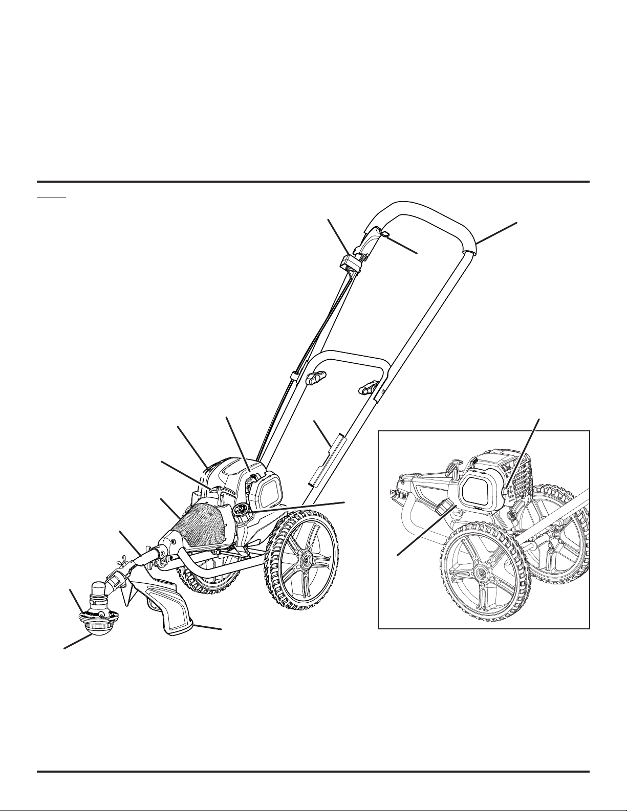
Fig. 1
F
G
E
O
D
C
I
L
H
J
B
A
M
N
A - Pro Cut II™ string head (tête à ligne de coupe de Pro Cut II, cabezal del
hilo de Pro Cut II)
B - String head/shaft assembly (ensemble d’arbre et de tête de coupe,
conjunto de eje/ cabezal del hilo)
C - Air intake screen (grille d’entrée d’air; pantalla de entrada de aire)
D - Starter grip and rope (poignée du lanceur et corde, mango del
arrancador y cuerda)
E - Choke lever (levier de volet de départ, palanca de arranque)
F - On/stop switch (commutateur marche / arrêt, interruptor de apagado)
K
G
- Throttle trigger (gâchette d’accélérateur, gatillo del acelerador)
H - Handlebar (poignée du guidon, barra del mango)
I
- Line carrier (support de fil, soporte de línea)
J - Primer bulb (poire d’amorçage, bomba de cebado)
K - Air filter cover (couvercle du filtre à air, tapa del filtro de aire)
L - Fuel cap (bouchon de carburant, tapa del tanque)
M- Grass deflector (déflecteur d’herbe, deflector de pasto)
N - Mow ball (tête de coupe, bola para cortar)
O - Muffler (silencieux, silenciador)
ii
Page 3
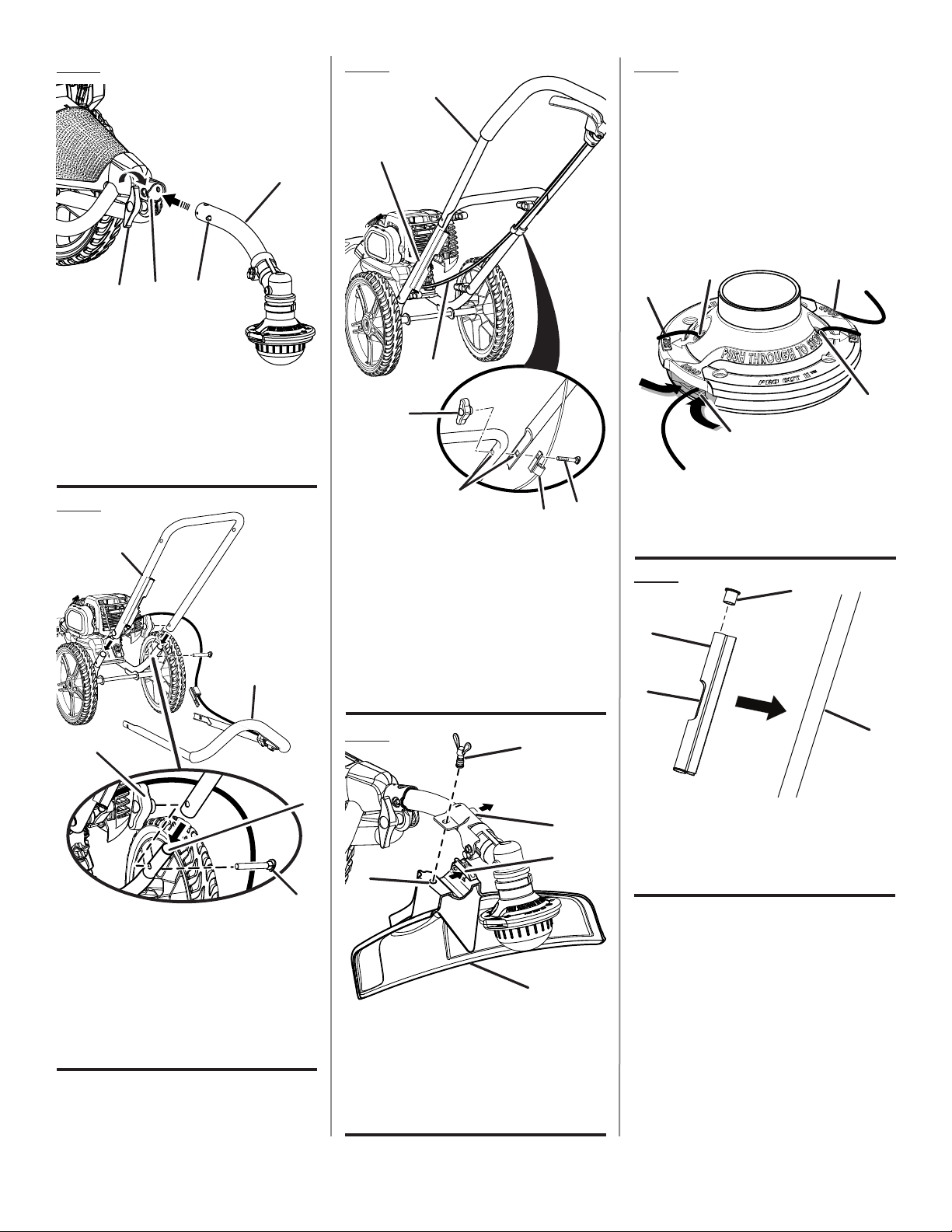
Fig. 2
D
C
B
A
A - Knob (bouton, perilla)
B - Guide recess (logement guide, hueco guía)
C - Button (bouton, botón)
D - String head/shaft assembly (ensemble
d’arbre et de tête de coupe, conjunto de eje/
cabezal del hilo)
Fig. 3
A
B
Fig. 4
B
A
C
D
E
G
F
A - Lower handlebar (guidon inférieur, mango
inferior)
B - Upper handlebar (guidon supérieur, mango
superior)
C - Throttle cable (câble d’accélérateur, cable
del acelerador)
D - Handlebar knob (bouton du guidon, perillas
de la barra del mango)
E - Holes (trous, orificios)
F - Clip (agrafe en plastique, pasador plástico)
G - Bolt (boulon, perno)
Fig. 6
INSERT LINE THROUGH SLOTS UNTIL
APPROX. 1 in. PROTRUDES FROM HOLES
INSÉRER LES FILS DANS LES FENTES
DE MANIÈRE À LES FAIRE DÉPASSER
D’ENVIRON 25,4 mm (1 po)
INTRODUZCA LOS HILOS A TRAVÉS
DE LAS RANURAS HASTA QUE
SOBRESALGAN APROXIMADAMENTE
25,4 mm (1 pulg.) DE LOS ORIFICIOS
CB
A
B
C
A - Pull line from holes to remove (tirer les fils
hors des trous afin de les retirer, tire de los
hilos para retirarlos a través de los orificios)
B - Hole (trou, agujero)
C - Slot (fente, ranura)
Fig. 7
C
B
D
C
D
E
A - Lower handlebar (guidon inférieur, barra del
mango inferior)
B - Upper handlebar (guidon supérieur, barra
del mango superior)
C - Handlebar knob (bouton du guidon inférieur,
perilla de la barra del mango inferior)
D - Frame opening (ouverture du cadre, abertura
del bastidor)
E - Bolt (boulon, perno)
Fig. 5
A
B
C
D
E
A - Wing screw (vis à oreilles, tornillo de
mariposa)
B - Tab (languette, orejeta)
C - Slot (fente, ranura)
D - Hole (trou, agujero)
E - Grass deflector (déflecteur d’herbe, deflector
de pasto)
A
A - Lower handlebar (guidon inférieur, barra del
mango inferior)
B - Line carrier (support de fil, soporte de línea)
C -
Top cap (couvercle supérieure, tapa superior)
D - Open area (partie ouverte, área abierta)
iii
Page 4
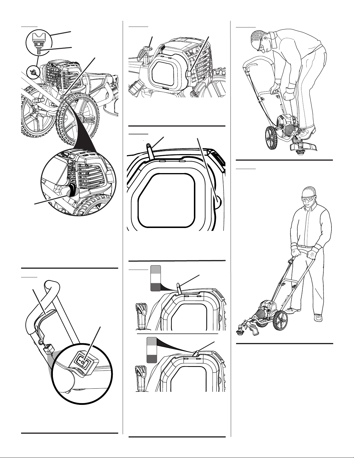
Fig. 8
FULL
CHOKE
RUN
HALF
CHOKE
1. PRESS PRIMER BULB 10X
2. SET TO
3. PULL UNTIL UNIT ATTEMPTS
TO START (MAX 4X)
(DO NOT PULL THROTTLE TRIGGER)
4. SET TO
5. PULL UNTIL UNIT STARTS
6. WAIT 10 SECONDS
7. SET TO
FULL CHOKE
HALF CHOKE
RUN
7. SET TO
RUN
Fig. 10
A
A
B
Fig. 13
B
C
A - Starter grip and rope (poignée du lanceur et
corde, mango del arrancador y cuerda)
B - Primer bulb (poire d’amorçage, bomba de
cebado)
D
A - Oil cap/dipstick (bouchon/jauge d’huile, tapa
de aceite/varilla para medir el aceite)
B - Fill line (ligne de remplissage, línea de
llenado)
C - Oil fill hole (orifice de remplissage d’huile,
agujero de llenado de aceite)
D - Funnel (entonnoir, embudo)
Fig. 9
B
A
Fig. 11
A
B
A - Choke lever (levier de volet de départ,
palanca de arranque)
B - Primer bulb (poire d’amorçage, bomba de
cebado)
Fig. 12
RUN
HALF
CHOKE
A
FULL
CHOKE
1. PRESS PRIMER BULB 10X
2. SET TO
3. PULL UNTIL UNIT ATTEMPTS
TO START (MAX 4X)
(DO NOT PULL THROTTLE TRIGGER)
4. SET TO
5. PULL UNTIL UNIT STARTS
6. WAIT 10 SECONDS
7. SET TO
B
FULL CHOKE
HALF CHOKE
RUN
Fig. 14
PROPER OPERATING POSITION
BONNE POSITION
DE TRAVAIL
POSICIÓN CORRECTA
PARA EL MANEJO
DE LA HERRAMIENTA
A - On/stop switch (commutateur marche /
arrêt, interruptor de apagado)
B - Throttle trigger (gâchette d’accélérateur,
gatillo del acelerador)
RUN
C
HALF
CHOKE
FULL
CHOKE
1. PRESS PRIMER BULB 10X
FULL CHOKE
2. SET TO
3. PULL UNTIL UNIT ATTEMPTS
TO START (MAX 4X)
(DO NOT PULL THROTTLE TRIGGER)
4. SET TO
HALF CHOKE
5. PULL UNTIL UNIT STARTS
6. WAIT 10 SECONDS
B
A - Full choke position (position de
complètement ouvert, posición de anegación
máxima)
B - Choke lever (levier de volet de départ,
palanca del anegador)
C - Run position (position de marche , posición
de marcha)
iv
Page 5
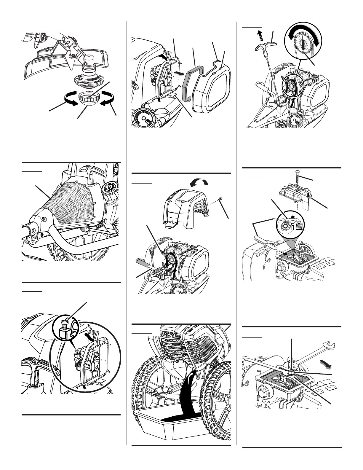
Fig. 15
Fig. 18
Fig. 21
A
D
C
B
E
B
B
D
A
A - Mow ball (tête de coupe, bola para cortar)
B - Hex Bolt (boulon six pans, perno de cabeza
hexagona)
C - Loosen (desserrer, aflojamiento)
D - Tighten (aflojar, apriete)
C
Fig. 16
A
A - Air intake screen (grille d’entrée d’air;
pantalla de entrada de aire)
A
A - Latch (loquet, pestillo)
B - Air filter cover (couvercle du filtre à air, tapa
del filtro de aire)
C - Air filter (filtre à air, filtro de aire)
D - Tabs (languettes, orejetas)
E - Slots (fentes, ranuras)
Fig. 19
A
C
B
A - Starter grip and rope (poignée du lanceur et
corde, mango del arrancador y cuerda)
B - Deep hole in camshaft gear (trou profond
situé dans l’engrenage de l’arbre à cames,
orificio profundo en el engranaje del árbol de
levas)
Fig. 22
D
B
C
A
Fig. 17
A
A - Idle speed screw (vis de ralenti, tornillo de
ajuste de la velocidad en vacío)
A - Spark plug (bougie, bujía)
B - Screw (vis, tornillo)
C - Spark plug wire (fil de la bougie, cable de la
bujía)
Fig. 20
v
A - Feeler gauge (jauge d’épaisseur, calibrador
de separaciones)
B - Rocker arm (culbuteur, balancín)
C - Rocker arm cover (cache -culasse, tapa del
balancín)
D - Screw (vis, tornillo)
Fig. 23
C
B
A
A - Retaining nut (écrou de retenue, tuerca de
retencion)
B - Adjusting nut (écrou de réglage, tuerca de
ajuste)
C - Stud (goujon, elemento estructural)
Page 6

TABLE OF CONTENTS
TABLE DES MATIÈRES / ÍNDICE DE CONTENIDO
Introduction ......................................................................................................................................................................2
Introduction / Introducción
General Safety Rules ........................................................................................................................................................ 3
Règles de sécurité générales / Reglas de seguridad generales ........................................................................................................ 3-4
Specific Safety Rules ........................................................................................................................................................ 4
Règles de sécurité particulières / Reglas de seguridad específicas
Symbols ............................................................................................................................................................................ 5
Symboles / Símbolos
Features ............................................................................................................................................................................6
Caractéristiques / Características
Assembly .......................................................................................................................................................................6-8
Assemblage / Armado ...............................................................................................................................................................6-7 / 6-8
Operation .......................................................................................................................................................................8-9
Utilisation / Funcionamiento
Maintenance ..............................................................................................................................................................10-12
Entretien / Mantenimiento
Troubleshooting .............................................................................................................................................................. 13
Dépannage / Solución de problemas
Warranty .........................................................................................................................................................................14
Garantie / Garantía
Parts Ordering and Service ...............................................................................................................................Back page
Commande de pièces et réparation / Pedidos de piezas y servicio .........................................................páge arrière / pág. posterior
INTRODUCTION
INTRODUCTION / INTRODUCCIÓN
This product has many features for making its use more pleasant and enjoyable. Safety, performance, and dependability
have been given top priority in the design of this product making it easy to maintain and operate.
* * *
Ce produit offre de nombreuses fonctions destinées à rendre son utilisation plus plaisante et satisfaisante. Lors de la
conception de ce produit, l’accent a été mis sur la sécurité, les performances et la fiabilité, afin d’en faire un outil facile à
utiliser et à entretenir.
* * *
Este producto ofrece numerosas características para hacer más agradable y placentero su uso. En el diseño de este producto
se ha conferido prioridad a la seguridad, el desempeño y la fiabilidad, por lo cual se facilita su manejo y mantenimiento.
2
Page 7

GENERAL SAFETY RULES
WARNING:
Read and understand all instructions. Failure to follow all
instructions listed below may result in electric shock, fire
and/or serious personal injury.
READ ALL INSTRUCTIONS
For safe operation, read and understand all instructions
before using this product. Follow all safety instructions.
Failure to follow all safety instructions listed below, can
result in serious personal injury.
Do not allow children or untrained individuals to use this
unit.
Do not start or operate the engine in a confined space,
building, near open windows, or in other unventilated space
where dangerous carbon monoxide fumes can collect.
Carbon monoxide, a colorless, odorless, and extremely
dangerous gas, can cause unconsciousness or death.
Clear the work area before each use. Remove all objects
such as rocks, broken glass, nails, wire, or string which
can be thrown or become entangled in the cutting line.
Always wear eye protection with side shields marked to
comply with ANSI Z87.1, along with hearing protection
when operating this product.
Wear heavy, long pants, long sleeves, boots, and gloves.
Do not wear loose fitting clothing, short pants, sandals,
or go barefoot. Do not wear jewelry of any kind.
Heavy protective clothing may increase operator fatigue,
which could lead to heat stroke. During weather that is
hot and humid, heavy work should be scheduled for early
morning or late afternoon hours when temperatures are
cooler.
Product users on United States Forest Service land, and in
some states, must comply with fire prevention regulations.
This product is equipped with a spark arrestor; however,
other user requirements may apply. Check with your
federal, state, or local authorities.
Secure long hair above shoulder level to prevent
entanglement in moving parts.
Keep all bystanders, children, and pets at least
50 ft. away. Bystanders should be encouraged to wear
eye protection. If you are approached, stop the engine
and cutting attachment.
Do not operate this unit when you are tired, ill, upset or
under the influence of alcohol, drugs, or medication.
Do not operate in poor lighting.
Keep firm footing and balance. Do not overreach.
Overreaching can result in loss of balance or exposure
to hot surfaces.
Keep all parts of your body away from any moving part.
Do not touch area around the muffler or cylinder of the
unit; these parts get hot from operation.
Always stop the engine and remove the spark plug wire
before making any adjustments or repairs except for
carburetor adjustments.
Inspect the unit before each use for loose fasteners, fuel
leaks, etc. Replace any damaged parts before use.
The cutting attachment should never rotate at idle during
normal use. The cutting attachment may rotate at idle
during carburetor adjustments.
It has been reported that vibrations from gasoline powered
tools may contribute to a condition called Raynaud’s
Syndrome in certain individuals. Symptoms may include
tingling, numbness, and blanching of the fingers, usually
apparent upon exposure to cold. Hereditary factors,
exposure to cold and dampness, diet, smoking, and work
practices are all thought to contribute to the development
of these symptoms. It is presently unknown what, if any,
vibrations or extent of exposure may contribute to the
condition. There are measures that can be taken by the
operator to possibly reduce the effects of vibration:
a) Keep your body warm in cold weather. When operating
the unit wear gloves to keep hands and wrists warm.
It is reported that cold weather is a major factor contributing to Raynaud’s Syndrome.
b) After each period of operation, exercise to increase
blood circulation.
c) Take frequent work breaks. Limit the amount of
exposure per day.
d) Keep the tool well maintained, fasteners tightened,
and worn parts replaced.
If you experience any of the symptoms of this condition,
immediately discontinue use and see your physician about
these symptoms.
Store fuel in a container approved for gasoline.
Mix fuel outdoors where there are no sparks or flames.
Wipe up any fuel spillage. Move 30 ft. away from refueling
site before starting engine. Slowly remove the fuel cap
after stopping engine. Do not smoke when refueling.
Stop the engine and allow to cool before refueling or
storing the unit.
Allow the engine to cool, empty the fuel tank into a container
approved for gasoline, and secure the unit from moving
before transporting in a vehicle.
Wear your protective equipment and observe all safety
instructions. For units equipped with a clutch, be sure
the cutting attachment stops turning when the engine
idles. When the unit is turned off make sure the cutting
attachment has stopped before the unit is set down.
3 — English
Page 8

SPECIFIC SAFETY RULES
Inspect before use. Replace damaged parts. Make sure
fasteners are in place and secure. Check for fuel leaks.
Replace string head if cracked, chipped, or damaged in
any way. Be sure the string head is properly installed and
securely fastened. Failure to do so can cause serious
injury.
Make sure all guards, straps, deflectors, and handles are
properly and securely attached.
Never use blades, flailing devices, wire, or rope. Use
only the manufacturer’s replacement line in the cutting
head. Do not use any other cutting attachment. To install
any other type or brand of cutting head to this wheeled
trimmer can result in serious personal injury.
Never operate unit without the grass deflector in place
and in good condition.
This product is intended for infrequent use by homeown-
ers and other occasional users for such general applications as trimming light and heavy vegetation, etc. It is
not intended for prolonged use. Prolonged periods of
operation can cause circulatory problems in the user’s
hands due to vibration.
4 — English
Page 9

SYMBOLS
The following signal words and meanings are intended to explain the levels of risk associated with this product.
SYMBOL SIGNAL MEANING
DANGER:
WARNING:
CAUTION:
NOTICE:
Some of the following symbols may be used on this product. Please study them and learn their meaning for safe
operation of this product.
SYMBOL NAME EXPLANATION
Safety Alert Indicates a potential personal injury hazard.
Read Operator’s Manual
Eye and Hearing Protection
Indicates an imminently hazardous situation, which, if not avoided, will result
in death or serious injury.
Indicates a potentially hazardous situation, which, if not avoided, could result
in death or serious injury.
Indicates a potentially hazardous situation, which, if not avoided, may result in
minor or moderate injury.
(Without Safety Alert Symbol) Indicates important information not related to an
injury hazard, such as a situation that may result in property damage.
To reduce the risk of injury, user must read and understand operator’s manual before using this product.
Always wear eye protection with side shields marked to
comply with ANSI Z87.1, along with hearing protection.
Keep Bystanders Away Keep all bystanders at least 50 ft. away.
Ricochet
No Blade
Thrown objects can ricochet and result in personal injury
or property damage.
Do not install or use any type of blade on a product displaying this symbol.
5 — English
Page 10

FEATURES
PRODUCT SPECIFICATIONS
Weight - (Without Fuel) .......................................... 22.6 lbs.
Line Cutting Width ...................................................... 16 in.
Engine Displacement................................................... 30cc
Engine Lubricant Volume.......................................... 2.2 oz.
Fuel Volume ............................................................ 11.8 oz.
Line Diameter ........................................... .095 in. - .105 in.
KNOW YOUR WHEELED TRIMMER
See Figure 1.
The safe use of this product requires an understanding of
the information on the tool and in this operator’s manual as
well as a knowledge of the project you are attempting. Before
use of this product, familiarize yourself with all operating
features and safety rules.
CURVED SHAFT
The curved design of the trimmer shaft allows you to trim
perimeter areas easily.
ASSEMBLY
UNPACKING
This product requires assembly.
Carefully remove the product and any accessories from
the box. Make sure that all items listed in the packing list
are included.
NOTE: Be careful not to bend the throttle cable when
unpacking.
WARNING:
Do not use this product if any parts on the Packing List
are already assembled to your product when you unpack
it. Parts on this list are not assembled to the product by
the manufacturer and require customer installation. Use
of a product that may have been improperly assembled
could result in serious personal injury.
Inspect the product carefully to make sure no breakage
or damage occurred during shipping.
Do not discard the packing material until you have care-
fully inspected and satisfactorily operated the product.
If any parts are damaged or missing, please call
1-800-860-4050 for assistance.
ERGONOMIC DESIGN
The design of the trimmer provides for easy handling. It is
designed for comfort and ease of grasp when operating in
different positions and at different angles.
GRASS DEFLECTOR
The trimmer includes a grass deflector that helps protect
you from flying debris.
OIL CAP/DIPSTICK
Remove the oil fill cap to check and add lubricant when
necessary.
PACKING LIST
Trimmer Power Head/Wheel Assembly
Pro Cut II™ String Head/Shaft Assembly
Handle Assembly
Grass Deflector
Line Carrier
.105 in. Line (20 Pieces)
Paper Funnel
Bottle of 4-Cycle Lubricant
Operator’s Manual
WARNING:
If any parts are damaged or missing do not operate this
product until the parts are replaced. Use of this product
with damaged or missing parts could result in serious
personal injury.
WARNING:
Do not attempt to modify this product or create accessories not recommended for use with this product. Any
such alteration or modification is misuse and could result
in a hazardous condition leading to possible serious
personal injury.
6 — English
Page 11

ASSEMBLY
WARNING:
To prevent accidental starting that could cause serious
personal injury, always disconnect the engine spark plug
wire from the spark plug when assembling parts.
WARNING:
Be certain all knobs are fully tightened before operating
equipment; check them periodically for tightness during
use to avoid serious personal injury.
INSTALLING THE PRO CUT II™ STRING HEAD/
SHAFT ASSEMBLY TO THE TRIMMER POWER
HEAD/WHEEL ASSEMBLY
See Figure 2.
WARNING:
Never install, remove, or adjust any attachment while
the engine is running or cutting head is moving. Failure
to stop the engine and cutting head can cause serious
personal injury.
The Pro Cut II™ string head/shaft assembly connects to the
trimmer power head/wheel assembly by means of a coupler
device.
Loosen the knob on the coupler of the power head shaft
and remove the end cap from the string head/shaft
assembly.
Push in the button located on the string head shaft. Align
the button with the guide recess on the power head coupler
and slide the two shafts together. Rotate the string head
shaft until the button locks into the positioning hole.
NOTE: If the button does not release completely in the
positioning hole, the shafts are not locked into place.
Slightly rotate from side to side until the button is locked
into place.
Tighten the knob securely.
INSTALLING LOWER HANDLEBAR
See Figure 3.
Remove two handlebar knobs and two bolts from the
hardware bag.
Place the lower handlebar into the openings on the trimmer
power head/wheel assembly as shown.
NOTE: Do not allow throttle cable to become pinched
when installing the handlebar.
Insert the bolts through the holes in the handlebar and
frame.
Install the lower handlebar knobs and tighten securely.
INSTALLING UPPER HANDLEBAR
See Figure 4.
Remove two handlebar knobs and bolts from the hardware
bag.
7 — English
Position upper handlebar onto lower handlebar. Make
sure the throttle cable and throttle trigger are on the right
side as shown.
Insert bolt through plastic clip, then through holes.
NOTE: Do not allow throttle cable to become pinched
when installing the handlebar.
Align the holes in the clip, the upper handlebar and lower
handlebar.
Install bolt as shown.
Thread handlebar knob onto bolt and tighten securely.
Repeat with other side.
ATTACHING THE GRASS DEFLECTOR
See Figure 5.
WARNING:
The line cutting blade on the grass deflector is sharp.
Avoid contact with the blade. Failure to avoid contact
can result in serious personal injury.
Remove the wing screw from the grass deflector.
Insert the tab on the mounting bracket in the slot on the
grass deflector.
Align the screw hole in the mounting bracket with the
screw hole in the grass deflector.
Insert the wing screw through the mounting bracket and
into the grass deflector.
Tighten the screw securely.
INSTALLING LINE IN PRO CUT II™ STRING
HEAD
See Figure 6.
Use monofilament line between .095 in. and .105 in. diameter. Use quality monofilament replacement line for best
performance.
Stop the engine and disconnect the spark plug wire.
Gather two of the pre-cut lengths of trimmer line provided
or cut two pieces of trimmer line in 10 in. lengths.
Insert the lines into the slots located on the sides of the
string head. Line should be pushed in until approximately
1 in. protrudes from the holes on the top of the string
head.
Remove old line by pulling it from the holes located on
the top of the string head.
WARNING:
Do not remove screws or disassemble string head. If
head is opened, compression springs could fly out toward
operator and result in serious injury.
INSTALLING LINE CARRIER
See Figure 7.
The line carrier snaps onto the lower handlebar on the side
opposite the throttle cable and is used to hold pre-cut pieces
of trimmer line.
Page 12

ASSEMBLY
NOTE: Do not install the carrier where it could interfere with
the throttle cable or where it could cover any of the warning
icons or labels.
OPERATION
WARNING:
Do not allow familiarity with this product to make you
careless. Remember that a careless fraction of a second is
sufficient to inflict serious injury.
WARNING:
Always wear eye protection with side shields marked to
comply with ANSI Z87.1, along with hearing protection.
Failure to do so could result in objects being thrown into
your eyes and other possible serious injuries.
WARNING:
Never use blades, flailing devices, wire, or rope on this
product. Do not use any attachments or accessories not
recommended by the manufacturer of this product. The
use of attachments or accessories not recommended
can result in serious personal injury.
WARNING:
Operation of this equipment could create sparks that
can start fires around dry vegetation. A spark arrestor
could be required. The operator should contact local fire
agencies for laws or regulations relating to fire prevention
requirements.
OXYGENATED FUELS
NOTICE:
To install line, remove top cap, insert line into carrier, and
replace cap. To remove line for use, pull from open area on
front of carrier.
Ethanol. Gasoline containing up to 10% ethanol by volume
(commonly referred to as E10) is acceptable. E15 and E85
are not.
FUELING AND REFUELING THE TRIMMER
WARNING:
Gasoline and its vapors are highly flammable and explosive. To prevent serious personal injury and property
damage, handle it with care. Keep away from ignition
sources and open flames, handle outdoors only, do not
smoke and wipe up spills immediately.
Clean surface around fuel cap to prevent contamination.
Loosen fuel cap slowly by turning counterclockwise. Rest
the cap on a clean surface.
Carefully pour fuel into the tank. Avoid spillage.
Prior to replacing the fuel cap, clean and inspect the
gasket.
Immediately replace fuel cap and hand tighten by turning
it clockwise. Wipe up any fuel spillage.
NOTE: It is normal for smoke to be emitted from a new
engine after first use.
WARNING:
Always shut off engine before fueling. Never add fuel to a
machine with a running or hot engine. Move at least 30 ft.
from refueling site before starting engine. Do not smoke
and stay away from open flames and sparks. Failure to
safely handle fuel could result in serious personal injury.
Do not use E15 or E85 fuel (or fuel containing greater
than 10% ethanol) in this product. It is a violation of
federal law and will damage the unit and void your
warranty.
Fuel system damage or performance problems resulting
from the use of an oxygenated fuel containing more than
the percentage of oxygenates stated below are not covered
under warranty.
8 — English
Page 13

OPERATION
ADDING/CHECKING ENGINE LUBRICANT
See Figure 8.
NOTICE:
Attempting to start the engine before it has been properly
filled with lubricant will result in equipment failure.
Engine lubricant has a major influence on engine performance and service life. This unit is shipped with a 20W50
engine lubricant to assist in the break-in period. For best
operating performance, continuing to use 20W50 engine
lubricant is recommended, however, SAE 30, 10W30, or
10W40 are all acceptable lubricants to use in this product.
Always use a 4-stroke motor lubricant that meets or exceeds
the requirements for API service classification SJ. Check
lubricant level before each use.
NOTE: Non-detergent or 2-stroke engine lubricants will
damage the engine and should not be used.
To add engine lubricant:
Remove the cap and seal from lubricant bottle
provided.
Unscrew the oil cap/dipstick and remove.
Using the funnel provided, add one entire bottle of engine
lubricant through oil fill hole.
Reinstall the oil cap/dipstick and secure.
To check engine lubricant level:
Place unit on a flat surface.
Wipe dipstick clean and re-seat in hole; do not rethread.
Remove dipstick again and check lubricant level. Lubri-
cant level should fall within the 2 squares on dipstick.
If level is low, add engine lubricant until the fluid level
rises to the upper portion of the dipstick.
Replace and secure the oil cap/dipstick.
NOTICE:
Do not overfill. Overfilling the crankcase may cause
excessive smoke, oil loss, and engine damage.
STARTING AND STOPPING
See Figures 9 - 13.
Trimmer should be on a flat, bare surface for starting.
To start a cold engine:
Slowly press the primer bulb 10 times.
NOTE: After the 7th press, fuel should be visible in the
primer bulb. If it is not, continue to press the primer until
you see fuel in the bulb.
Set the choke lever to FULL CHOKE position.
NOTE: Do not squeeze the throttle trigger.
Pull the starter grip until the engine runs.
NOTE: If engine has not started after 3 pulls and:
outside temperature is 60°F or lower, leave the choke
in the FULL CHOKE position and continue to pull the
starter grip until the engine runs.
outside temperature is above 60°F, move the choke
to the HALF CHOKE position and continue to pull the
starter grip until the engine runs.
Allow the engine to run for 10 seconds, then set the choke
lever to the RUN position.
To restart a warm engine:
Slowly press the primer bulb 10 times.
Set the choke lever to the RUN position.
Pull the starter grip until the engine runs. Do not squeeze
the throttle trigger.
To stop the engine:
To stop the engine, depress the STOP switch to the stop
position “ ”.
IF ASSISTANCE IS REQUIRED FOR THIS PRODUCT:
Do not return this product to the retail store where it was
purchased. Please call our Customer Service Department
for any issues you may have.
For Help Call: 1-800-860-4050
CUTTING TIPS
See Figure 14.
Keep a firm grip with both hands while in operation.
If grass becomes wrapped around the string head, STOP
THE ENGINE, disconnect the spark plug wire, and remove
the grass.
Use the tip of line to do the cutting; do not force string
head into uncut grass.
Wire and picket fences cause extra line wear, even
breakage. Stone and brick walls, curbs, and wood may
wear line rapidly.
Avoid trees and shrubs. Tree bark, wood moldings, siding,
and fence posts can easily be damaged by the line.
TRANSPORTING THE UNIT
Flip on/stop switch to STOP ( O ) position.
Make sure engine and exhaust are cool.
Keep unit level to prevent fuel spillage.
9 — English
Page 14

MAINTENANCE
WARNING:
When servicing, use only identical replacement parts. Use
of any other parts can create a hazard or cause product
damage.
WARNING:
Always wear eye protection with side shields marked to
comply with ANSI Z87.1, along with hearing protection.
Failure to do so could result in objects being thrown into
your eyes and other possible serious injuries.
IDLE SPEED ADJUSTMENT
See Figure 17.
WARNING:
The cutting head will move when adjusting the idle speed.
Wear all protective clothing and keep all by standers,
children, and pets at least 50 ft. away. Make adjustments
with the unit supported by hand so that the cutting head
does not contact the ground or any object. Keep all parts
of your body away from the cutting head and muffler.
Failure to follow these instructions could result in serious
personal injury.
WARNING:
Before inspecting, cleaning, or servicing the machine, shut
off engine, wait for all moving parts to stop, and disconnect
spark plug wire and move it away from spark plug. Failure
to follow these instructions can result in serious personal
injury or property damage.
GENERAL MAINTENANCE
Avoid using solvents when cleaning plastic parts. Most plastics
are susceptible to damage from various types of commercial
solvents and may be damaged by their use. Use clean cloths
to remove dirt, dust, lubricant, grease, etc.
WARNING:
Do not at any time let brake fluids, gasoline, petroleumbased products, penetrating lubricants, etc., come in contact with plastic parts. Chemicals can damage, weaken or
destroy plastic which could result in serious personal injury.
You can often make adjustments and repairs described here.
For other repairs, have the trimmer serviced by an authorized
service dealer.
ACCESSING THE STRING HEAD
See Figure 15.
Rotate mow ball with hex bolt CLOCKWISE to loosen.
Remove mow ball with hex bolt from shaft.
To reattach mow ball:
Slide mow ball with hex bolt onto shaft.
Rotate COUNTER CLOCKWISE to tighten.
CLEANING THE AIR INTAKE SCREEN
See Figure 16.
If the air intake screen becomes clogged or dirty, air circulation
will decrease and engine performance will suffer.
To clean:
Stop the trimmer and disconnect the spark plug wire.
Allow the unit to cool, if necessary.
Using a dry cloth or nylon brush, remove dirt and debris
from screen.
If the cutting attachment turns at idle, the idle speed screw
needs adjusting on the engine. Turn the idle speed screw
counterclockwise to reduce the idle RPM and stop the cutting
attachment movement. If the cutting attachment still moves
at idle speed, contact a service dealer for adjustment and
discontinue use until the repair is made.
WARNING:
The cutting attachment should never turn at idle. Turn
the idle speed screw counterclockwise to reduce the idle
RPM and stop the cutting attachment, or contact a service
dealer for adjustment and discontinue use until the repair is
made. Serious personal injury could result from the cutting
attachment turning at idle.
CLEANING AIR FILTER
See Figure 18.
Clean the air filter as indicated by the maintenance schedule.
To clean the air filter:
Loosen the air filter cover by turning the knob
counterclockwise.
Remove the air filter cover.
Remove the air filter.
Lightly tap or blow out dirt particles from filter.
Reinstall the air filter.
NOTE: Make sure the filter is seated properly inside the
cover. Installing the filter incorrectly will allow dirt to enter
the engine, causing rapid engine wear.
Reinstall the cover.
Tighten knob to secure.
NOTE: For best performance, the air filter should be replaced once each year.
10 — English
Page 15

MAINTENANCE
FUEL CAP, TANK, AND LINES
WARNING:
Check for fuel leaks. A leaking fuel cap, tank, or lines are a
fire hazard and must be replaced immediately. If you find
any leaks, correct the problem before using the product.
Failure to do so could result in a fire that could cause serious personal injury.
The fuel cap contains a non-serviceable filter and a check
valve. A clogged fuel filter will cause poor engine performance.
If performance improves when the fuel cap is loosened,
check valve may be faulty or filter clogged. Replace fuel cap
if required.
SPARK PLUG REPLACEMENT
See Figure 19.
This engine uses a Champion RY4C spark plug with 0.025 in.
electrode gap. Use an exact replacement and replace annually.
Remove the screw on back of the engine housing. This will
allow the engine housing to uncover as shown.
Remove the spark plug wire.
Loosen the spark plug by turning it counterclockwise with
a socket wrench.
Remove the spark plug.
Hand thread the new spark plug, turning it clockwise.
Tighten with a socket wrench and torque to 170 in. lb.
minimum, 190 in. lb. maximum. Do not overtighten.
Secure the engine housing back into place and return the
screw. Ensure that the housing is stable.
NOTICE:
Be careful not to cross thread the spark plug. Cross threading will seriously damage the product.
CHANGING ENGINE LUBRICANT
See Figure 20.
WARNING:
Do not change engine lubricant while it is hot. Accidental
contact with hot engine lubricant could result in serious
burns.
For best performance, engine lubricant should be changed
after every 25 hours of operation.
To change the engine lubricant:
Stop the engine and disconnect the spark plug wire. Allow
the engine to cool completely before proceeding.
Remove the oil fill cap/dipstick.
Tip the unit backward so the handles rest on the ground
and allow lubricant to drain from the oil fill hole into an
approved container.
NOTE: Drain the lubricant while the engine is still warm
but not hot. Warm lubricant will drain quickly and more
completely.
Return the unit to an upright position and refill with lubricant
following the instructions in the Adding/Checking Engine
Lubricant section previously in this manual.
NOTE: Used lubricant should be disposed of at an approved
disposal site. See your local retailer for more information.
ADJUSTING CAMSHAFT-TO-ROCKER ARM
CLEARANCE
See Figures 21 - 23.
Inspect the camshaft-to-rocker arm clearance after every
25 hours of operation. This should be done in a clean, dustfree environment.
NOTE: This procedure requires partial disassembly of the
engine. If you are unsure if you are qualified to perform this
operation, take the unit to an authorized service center.
Stop the engine and disconnect the spark plug wire. Allow
the engine to cool completely before proceeding.
Remove the screw from the top engine cover. Remove
engine cover and set aside.
Using a Torx screwdriver, remove the screw from the rocker
arm cover. Remove the cover and set aside.
Position camshaft by pulling the recoil starter grip just
until the deep hole in the camshaft gear is located at the
6 o’clock position.
Place the feeler gauge under each rocker arm and measure
the gap. The gap should be between .006 in. (0.15 mm)
and .008 in. (0.20 mm) for both rocker arms.
NOTE: Use a standard automotive feeler gauge. The .006 in.
(0.15 mm) feeler gauge should slide between the rocker
arm and valve stem with a slight amount of resistance but
without binding. The 0.008 in. (0.20 mm) feeler gage should
not slide between the rocker arms and the cam lobes — it
should be held tight.
If the valve clearance is not between .006 in. (0.15 mm)
and .008 in. (0.20 mm), the clearance should be adjusted
as follows:
While holding a wrench on the flats of the adjusting nut
with one hand, loosen the retaining nut with a second
wrench as shown. Take care not to loosen the stud.
Rotate the adjusting nut until it touches the feeler gauge.
Once the gap setting is correct, hold the wrench on the
flats of the adjusting nut and retighten the retaining nut
securely.
Adjust the second rocker arm, if necessary.
Replace the rocker arm cover and screw; tighten securely.
Replace the top engine cover and screw; tighten securely.
WARNING:
Ensure all engine cover and all engine parts are completely
and properly reassembled before starting engine. Failure
to correctly reassemble engine could result in serious injury
or property damage.
11 — English
Page 16

MAINTENANCE
STORING THE PRODUCT
Clean all foreign material from the product. Store idle unit
indoors in a dry, well-ventilated area that is inaccessible to
children. Keep away from corrosive agents such as garden
chemicals and de-icing salts.
Abide by all ISO and local regulations for the safe storage
and handling of gasoline.
When storing 1 month or longer:
Drain all fuel from tank into a container approved for gasoline.
Run engine until it stops.
Inspect Clean Replace Replace
Maintenance For Damage Before Every Every 25 Hours Every
Part Each Use 5 Hours or Yearly 50 Hours
* AIR FILTER ASSY
includes:
Filter .................................................................................... X
* CARBURETOR ASSY
includes:
Gaskets ........................................ X
* FUEL TANK ASSY
includes:
Fuel Lines ..................................... X
Fuel Cap ....................................... X
Fuel Filter................................................................................................................... X
* IGNITION ASSY
includes:
Spark Plug ................................................................................................................. X
* NOTICE: THE USE OF EMISSION CONTROL COMPONENTS OTHER THAN THOSE DESIGNED FOR THIS UNIT
IS A VIOLATION OF FEDERAL LAW.
MAINTENANCE SCHEDULE
HIGH ALTITUDE ENGINE OPERATION
Please have an authorized service center adjust this engine
if it is to be run above 2000 feet. Failure to do so may result
in poor engine performance and increased emissions. An
engine adjusted for high altitudes can not be run at 2000
feet or lower. In doing so, the engine will overheat and cause
serious engine damage. Please have an authorized service
center restore high altitude modified engines to the original
factory specification before operating below 2000 feet.
CALL US FIRST
For any questions about operating or maintaining your product,
call the Ryobi® Help Line!
Your product has been fully tested prior to shipment to ensure
your complete satisfaction.
12 — English
Page 17

TROUBLESHOOTING
IF THESE SOLUTIONS DO NOT SOLVE THE PROBLEM CONTACT YOUR AUTHORIZED SERVICE DEALER.
PROBLEM POSSIBLE CAUSE SOLUTION
Engine will not start
Engine does not reach full speed and
emits excessive smoke
No spark.
No fuel.
Engine is flooded.
Air filter is dirty.
Spark arrestor screen is dirty.
Spark plug fouled.
Clean or replace spark plug. Reset
spark plug gap. Refer to Spark Plug
Replacement earlier in this manual.
Push primer bulb until bulb is full of fuel.
If bulb does not fill, primary fuel delivery
system is blocked. Contact a service
dealer. If primer bulb fills, engine may
be flooded, proceed to next item.
Set the start lever to the START position.
Squeeze the trigger and pull the rope
repeatedly until the engine starts and
runs.
NOTE: Depending on the severity of
the flooding, this may require numerous
pulls of the rope.
Clean air filter. Refer to Cleaning Air
Filter earlier in this manual.
Contact a servicing dealer.
Clean or replace spark plug. Reset
spark plug gap. Refer to Spark Plug
Replacement earlier in this manual.
Engine starts, runs, and accelerates
but will not idle
Spool retainer hard to turn Screw threads are dirty or damaged. Clean threads and lubricate with grease
Grass wraps around driveshaft housing
and string head
Engine emits too much smoke Too much oil in crankcase. Drain lubricant and refill with correct
Engine rope cannot be pulled Oil has entered the combustion
Idle speed screw on carburetor needs
adjustment.
Cutting tall grass at ground level.
Operating trimmer at part throttle.
chamber.
Turn idle speed screw clockwise to
increase idle speed. See Figure 17.
- if no improvement, replace the spool
retainer.
Cut tall grass from the top down to
prevent wrapping.
Operate trimmer at full throttle.
amount of 10W-30 engine lubricant.
See Adding/Checking Engine
Lubricant in the Operation section of
this manual.
This is usually caused by storing the unit
for an extended time with the engine in
an upside-down position. Remove and
clean the spark plug. Drain the oil out
of the spark plug hole, then reinstall the
spark plug.
13 — English
Page 18

WARRANTY
LIMITED WARRANTY STATEMENT
Techtronic Industries North America, Inc., warrants to the
original retail purchaser that this RYOBI® brand outdoor
product is free from defect in material and workmanship
and agrees to repair or replace, at Techtronic Industries
North America, Inc.’s, discretion, any defective product
free of charge within these time periods from the date of
purchase.
Three years if the product is used for personal, family
or household use;
90 days, if used for any other purpose, such as
commercial or rental.
This warranty extends to the original retail purchaser
only and commences on the date of the original retail
purchase.
Any part of this product found in the reasonable judgment
of Techtronic Industries North America, Inc. to be defective
in material or workmanship will be repaired or replaced
without charge for parts and labor by an authorized service
center for RYOBI® brand outdoor products (Authorized
Ryobi Service Center).
The product, including any defective part, must be returned
to an authorized Ryobi service center within the warranty
period. The expense of delivering the product to the service
center for warranty work and the expense of returning it
back to the owner after repair or replacement will be paid
by the owner. Techtronic Industries North America, Inc.’s,
responsibility in respect to claims is limited to making the
required repairs or replacements and no claim of breach
of warranty shall be cause for cancellation or rescission
of the contract of sale of any RYOBI® brand outdoor
product. Proof of purchase will be required by the dealer
to substantiate any warranty claim. All warranty work must
be performed by an authorized service dealer.
This warranty is limited to ninety (90) days from the date
of original retail purchase for any RYOBI® brand outdoor
product that is used for rental or commercial purposes, or
any other income-producing purpose.
This warranty does not cover any product that has been
subject to misuse, neglect, negligence, or accident, or that
has been operated in any way contrary to the operating
instructions as specified in this operator’s manual. This
warranty does not apply to any damage to the product that
is the result of improper maintenance or to any product
that has been altered or modified. The warranty does not
extend to repairs made necessary by normal wear or by the
use of parts or accessories which are either incompatible
with the RYOBI® brand outdoor product or adversely affect
its operation, performance, or durability. In addition, this
warranty does not cover:
A. Tune-ups – Spark Plugs, Carburetor, Carburetor
Adjustments, Ignition, Filters
B. Wear items – Bump Knobs, Outer Spools, Cutting
Lines, Inner Reels, Starter Pulleys, Starter Ropes, Drive
Belts, Tines, Felt Washers, Hitch Pins, Mulching Blades,
Blower Fans, Blower and Vacuum Tubes, Vacuum Bag
and Straps, Guide Bars, Saw Chains
Techtronic Industries North America, Inc., reserves the right
to change or improve the design of any RYOBI® brand
outdoor product without assuming any obligation to modify
any product previously manufactured.
ALL IMPLIED WARRANTIES ARE LIMITED IN DURATION
TO THE STATED WARRANTY PERIOD. ACCORDINGLY,
ANY SUCH IMPLIED WARRANTIES INCLUDING
MERCHANTABILITY, FITNESS FOR A PARTICULAR
PURPOSE, OR OTHERWISE, ARE DISCLAIMED IN THEIR
ENTIRETY AFTER THE EXPIRATION OF THE APPROPRIATE
THREE-YEAR, TWO-YEAR, ONE-YEAR, OR NINETYDAY WARRANTY PERIOD. TECHTRONIC INDUSTRIES
NORTH AMERICA, INC.’S, OBLIGATION UNDER THIS
WARRANTY IS STRICTLY AND EXCLUSIVELY LIMITED TO
THE REPAIR OR REPLACEMENT OF DEFECTIVE PARTS
AND TECHTRONIC INDUSTRIES NORTH AMERICA,
INC., DOES NOT ASSUME OR AUTHORIZE ANYONE
TO ASSUME FOR THEM ANY OTHER OBLIGATION.
SOME STATES DO NOT ALLOW LIMITATIONS ON HOW
LONG AN IMPLIED WARRANTY LASTS, SO THE ABOVE
LIMITATION MAY NOT APPLY TO YOU. TECHTRONIC
INDUSTRIES NORTH AMERICA, INC., ASSUMES NO
RESPONSIBILITY FOR INCIDENTAL, CONSEQUENTIAL,
OR OTHER DAMAGES INCLUDING, BUT NOT LIMITED
TO, EXPENSE OF RETURNING THE PRODUCT TO AN
AUTHORIZED RYOBI SERVICE CENTER AND EXPENSE
OF DELIVERING IT BACK TO THE OWNER, MECHANIC’S
TRAVEL TIME, TELEPHONE OR TELEGRAM CHARGES,
RENTAL OF A LIKE PRODUCT DURING THE TIME
WARRANTY SERVICE IS BEING PERFORMED, TRAVEL,
LOSS OR DAMAGE TO PERSONAL PROPERTY, LOSS
OF REVENUE, LOSS OF USE OF THE PRODUCT, LOSS
OF TIME, OR INCONVENIENCE. SOME STATES DO NOT
ALLOW THE EXCLUSION OR LIMITATION OF INCIDENTAL
OR CONSEQUENTIAL DAMAGES, SO THE ABOVE
LIMITATION OR EXCLUSION MAY NOT APPLY TO YOU.
This warranty gives you specific legal rights, and you may
also have other rights which vary from state to state.
This warranty applies to all RYOBI® brand outdoor products
manufactured by or for Techtronic Industries North America,
Inc., and sold in the United States and Canada.
To locate your nearest Authorized Ryobi Service Center,
dial 1-800-860-4050.
14 — English
Page 19

RÈGLES DE SÉCURITÉ GÉNÉRALES
AVERTISSEMENT :
Lire et veiller à bien comprendre toutes les instructions.
Le non respect des instructions ci-dessous peut entraîner
un choc électrique, un incendie et / ou des blessures
graves.
LIRE TOUTES LES INSTRUCTIONS
Pour travailler en toute sécurité, lire et veiller à bien
comprendre toutes les instructions avant d’utiliser ce
produit. Respecter toutes les instructions de sécurité.
Le non respect des instructions de sécurité ci-dessous
peut entraîner des blessures graves.
Ne pas laisser des enfants ou personnes n’ayant pas reçu
une formation adéquate utiliser cet outil.
Ne pas mettre le moteur en marche ni le faire fonctionner
dans un espace confiné, un immeuble, près d’une fenêtre
ouverte ou dans tout autre espace non aéré où les vapeurs
nocives de monoxyde de carbone pourrait s’infiltrer.
Le monoxyde de carbone, un gaz incolore, inodore et
extrêmement toxique peut causer l’inconscience voire
la mort.
Déblayer la zone de travail avant chaque utilisation. La
débarrasser de tous les objets tels que cailloux, verre
brisé, clous, fils métalliques, cordes, etc. risquant d’être
projetés ou de se prendre dans la ligne de coupe.
Toujours porter une protection oculaire avec écrans
latéraux certifiée conforme à la norme ANSI Z87.1, avec
protection auditive, lors de l’utilisation de produit.
Porter des pantalons longs, manches longues, des
chaussures de travail et des gants épais. Ne pas porter
de vêtements amples, bijoux, shorts, sandales et ne pas
travailler pieds nus. Ne porter aucun bijou.
Le fait de porter des vêtements de protection lourds
peut augmenter la fatigue de l’utilisateur, ce qui pourrait
entraîner un coup de chaleur. Si le temps est chaud et
humide, effectuer les gros travaux le matin ou en fin
d’après-midi, alors qu’il fait plus frais.
Les produits utilisés sur les territoires des services
forestiers des États-Unis et de certains états doivent être
conformes aux réglementations de lutte contre l’incendie.
Cet outil est doté d’un pare-étincelles, toutefois, d’autres
dispositifs peuvent être requis. Consulter les autorités
locales et gouvernementales.
Attacher les cheveux longs pour les maintenir au-dessus
des épaules, afin qu’ils ne se prennent pas dans les pièces
en mouvement.
Garder les badauds, enfants et visiteurs à une distance
de 15 m (50 pi). Recommander aux personnes présente
de porter une protection oculaire.
Ne pas utiliser cet outil en état de fatigue, si l’on est
souffrant, contrarié, ou sous l’influence de l’alcool, de
drogues ou de médicaments.
3 — Français
Ne pas travailler sous un éclairage insuffisant.
Se tenir bien campé et en équilibre. Ne pas travailler
hors de portée. Le travail hors de portée risque de faire
perdre l’équilibre ou de causer un contact avec les pièces
brûlantes.
Garder toutes les parties du corps à l’écart des pièces
en mouvement.
Ne pas toucher les alentours de l’échappement ou du
cylindre, qui deviennent brûlants pendant l’utilisation.
Toujours arrêter le moteur et débrancher le fil de la bougie
avant d’effectuer tout entretien ou réglage, à l’exception
des réglages du carburateur.
Inspecter l’outil avant chaque utilisation pour s’assurer qu’il
n’y a pas de pièces desserrées, de fuites ce carburant,
etc. Remplacer les pièces endommagées avant utilisation.
Lors d’une utilisation normale, l’accessoire de coupe ne
doit jamais tourner au ralenti. La rotation au ralenti est
toutefois permise lors du réglage du carburateur.
Il a été rapporté que, chez certaines personnes, les
vibrations produites par les outils motorisés peuvent
contribuer au développement d’une affection appelée
syndrome de Raynaud. Les symptômes peuvent inclure
des picotements, l’insensibilisation et le blanchissement
des doigts et sont habituellement provoqués par
l’exposition au froid. L’hérédité, l’exposition au froid et à
l’humidité, le régime alimentaire, la fumée et les habitudes
de travail sont tous des facteurs considérés comme
contribuant au développement de ces symptômes. Il
n’existe actuellement aucune preuve qu’un certain type de
vibration ou le degré d’exposition contribue réellement au
développement de cette affectation. Certaines mesures,
susceptibles de réduire les effets des vibrations, peuvent
être prises par l’opérateur :
a) Garder le corps au chaud par temps froid. Pendant
l’utilisation, porter des gants afin de tenir les mains et
les poignets au chaud. Il a été établi que le froid est
l’une des principales causes du symptôme de Raynaud.
b) Après chaque période d’utilisation, faire des exercices
pour accroître la circulation.
c) Faire des pauses fréquentes. Limiter la durée
d’exposition quotidienne.
d) Garder l’outil bien entretenu, toutes les pièces de
boulonnerie serrées et remplacer les pièces usées.
En cas d’apparition de l’un ou plusieurs des symptômes
décrits ci-dessus, cesser d’utiliser l’outil et consulter un
médecin.
Conserver le carburant dans un bidon ou jerrican approuvé
pour l’essence.
Mélanger le carburant à l’extérieur, loin de toute flamme
ou source d’étincelles. Essuyer tout carburant répandu.
S’éloigner de 9 m (30 pi) du point d’approvisionnement
avant de lancer le moteur. Desserrer le bouchon du
Page 20

RÈGLES DE SÉCURITÉ GÉNÉRALES
réservoir de carburant lentement une fois que le moteur
est arrêté. Ne pas fumer pendant le ravitaillement en
carburant.
Arrêter le moteur et le laisser refroidir avant de faire le
plein ou de le remiser.
Pour le transport dans un véhicule, le réservoir doit être
vidé dans un bidon ou jerrycan approuvé pour l’essence
et l’outil bien arrimé.
RÈGLES DE SÉCURITÉ PARTICULIÈRES
Inspecter l’outil avant chaque utilisation. Remplacer les
pièces endommagées. S’assurer que toutes les pièces
de boulonnerie sont en place et bien serrées. S’assurer
de l’absence de fuites de carburant.
Si la tête de coupe est fendue, brisée ou endommagée
de quelque façon que ce soit, la remplacer. S’assurer que
la tête de coupe est correctement installée et solidement
assujettie. Ne pas prendre cette précaution peut entraîner
des risques de blessures graves.
S’assurer que tous les dispositifs de protection, sangles,
déflecteurs et poignées sont correctement installés et
solidement assujettis.
Ne jamais utiliser de lames ou de dispositifs à fléau, fil
et cordes. Utiliser exclusivement des lignes de coupe
Porter un équipement de protection et respecter
toutes les instructions de sécurité. Si l’outil est équipé
d’un embrayage, s’assurer que l’accessoire de coupe
s’immobilise lorsque le moteur tourne au ralenti. Lorsque
le moteur est arrêté, s’assurer que l’accessoire de coupe
est immobilisé avant de poser l’outil.
d’origine. Ne pas utiliser d’autres accessoires de coupe.
L’utilisation d’une tête de coupe d’autre type ou marque
sur ce taille-bordures à roues peut entraîner des blessures
graves.
Ne jamais utiliser l’appareil si le déflecteur d’herbe n’est
pas en place et en bon état.
Ce produit est conçu pour les personnes qui prévoient
l’utiliser de manière peu fréquente pour des applications
générales par exemple, tailler la végétation faible et dense
etc.; l’outil peut également convenir à d’autres utilisateurs
occasionnels. Elle n’est pas conçue pour un usage
prolongé. Les périodes d’utilisation prolongée peuvent
entraîner des problèmes circulatoires dans les mains de
l’opérateur, causés par les vibrations.
4 — Français
Page 21
SYMBOLES
Les termes de mise en garde suivants et leur signification ont pour but d’expliquer le degré de risques associé à l’utilisation
de ce produit.
SYMBOLE SIGNAL SIGNIFICATION
DANGER :
AVERTISSEMENT :
ATTENTION :
AVIS :
Certains des symboles ci-dessous peuvent être utilisés sur le produit. Veiller à les étudier et apprendre leur signification
pour assurer la sécurité d’utilisation.
SYMBOLE NOM EXPLICATION
Symbole d’alerte de sécurité Indique un risque de blessure potentiel.
Lire le manuel d’utilisation
Porter une protection oculaire et
auditive
Indique une situation extrêmement dangereuse qui, si elle n’est pas évitée,
aura pour conséquences des blessures graves ou mortelles.
Indique une situation potentiellement dangereuse qui, si elle n’est pas évitée,
pourrait entraîner des blessures graves ou mortelles.
Indique une situation potentiellement dangereuse qui, si elle n’est pas évitée,
pourraît entraîner des blessures légères ou de gravité modérée.
(Sans symbole d’alerte de sécurité) Indique une information importante
ne concernant pas un risque de blessure comme une situation pouvant
occasionner des dommages matériels.
Pour réduire les risques de blessures, l’utilisateur doit lire
et veiller à bien comprendre le manuel d’utilisation avant
d’utiliser ce produit.
Toujours porter une protection oculaire avec écrans
latéraux certifiée conforme à la norme ANSI Z87.1, avec
protection auditive.
Ne laisser personne s’approcher
Ricochet
Ne pas utiliser de lame
Garder les badauds à une distance de 15 m (50 pi)
minimum.
Les objets projetés peuvent ricocher et infliger des
blessures ou causer des dommages matériels.
Ne jamais utiliser une lame quelconque sur un outil
portant ce symbole.
5 — Français
Page 22

CARACTÉRISTIQUES
FICHE TECHNIQUE
Poids - (sans carburant) ............................ 10,2 kg (22,6 lb)
Largeur de coupe avec ligne ................... 406,4 mm (16 po)
Cylindrée ................................................................... 30 cc
Volume de lubrifiant moteur ......................................65 ml
Volume de carburant ................................................ 350 ml
Diamètre de coupe ..............................................................
.......................2,4 mm à 2,6 mm (0,095 po à 0,105 po)
APPRENDRE À CONNAÎTRE LE TAILLEBORDURES SUR ROUES
Voir la figure 1.
L’utilisation sûre de ce produit exige une comprehension
des renseignements figurant sur l’outil et contenus dans le
manuel d’utilisation, ainsi qu’une bonne connaissance du
projet entrepris. Avant d’utiliser ce produit, se familiariser
avec toutes ses caractéristiques et règles de sécurité.
ARBRE COURBE
La conception courbée de l’arbre du taille bordures permet
de tailler facilement les bordures.
ASSEMBLAGE
DÉBALLAGE
Ce produit doit être assemblé.
Avec précaution, sortir le produit et les accessoires de la
boîte. S’assurer que toutes les pièces figurant sur la liste
de contrôle sont incluses.
NOTE : Prendre garde de ne pas plier le câble
d’accélérateur en déballant l’outil.
AVERTISSEMENT :
Ne pas utiliser le produit si, en le déballant, vous
constatez que des éléments figurant dans la liste de
contrôle d’expédition sont déjà assemblés. Certaines
pièces figurant sur cette liste n’ont pas été assemblées
par le fabricant et exigent une installation. Le fait d’utiliser
un produit qui a été assemblé de façon inadéquate peut
entraîner des blessures.
Examiner soigneusement le produit pour s’assurer
que rien n’a été brisé ou endommagé en cours de
transport.
Ne pas jeter les matériaux d’emballage avant d’avoir
soigneusement examiné le produit et avoir vérifié qu’il
fonctionne correctement.
Si des pièces sont manquantes ou endommagées,
appeler le 1-800-860-4050.
CONCEPTION ERGONOMIQUE
Ce produit est conçu pour être extrêmement maniable. L’outil
est conçu pour pouvoir être tenu confortablement et aisément
dans différentes positions et à différents angles.
DÉFLECTEUR D’HERBE
Le taille-bordures est équipé d’un déflecteur d’herbe qui
protège l’opérateur des débris projetés.
BOUCHON/JAUGE D’HUILE
Retirer le bouchon de remplissage d’huile pour vérifier le
niveau de lubrifiant et faire l’appoint selon le besoin.
LISTE DE CONTRÔLE D’EXPÉDITION
Ensemble de bloc moteur et de roues du taille-bordures
Ensemble d’arbre et de tête de coupe Pro Cut II
Ensemble de poignée
Déflecteur d’herbe
Support de fil
Fil de 2,7 mm (0,105 po) (20 pièces)
Entonnoir
Flacon de lubrifiant 4 temps
Manuel d’utilisation
™
AVERTISSEMENT :
Si des pièces manquent ou sont endommagées, ne pas
utiliser ce produit avant qu’elles aient été remplacées.
Le fait d’utiliser ce produit même s’il contient des pièces
endommagées ou s’il lui manque des pièces peut
entraîner des blessures graves.
AVERTISSEMENT :
Ne pas essayer de modifier ce produit ou de créer des
accessoires non recommandés pour la produit. De telles
altérations ou modifications sont considérées comme un
usage abusif et peuvent créer des conditions dangereuses,
risquant d’entraîner des blessures graves.
6 — Français
Page 23

ASSEMBLAGE
AVERTISSEMENT :
Pour empêcher un démarrage accidentel pouvant entraîner
des blessures graves, toujours déconnecter le fil de bougie
de moteur de la bougie d’allumage avant d’assembler des
pièces.
Insérer le boulon par agrafe en plastique, puis par les trous.
NOTE : Attention de ne pas coincer le câble d’accélérateur
au moment d’installer le guidon.
Aligner la trous dans le pince avec la trous dans le guidon
supérieur et la trous dans le guidon inférieur.
Insérer boulon comme.
Visser le bouton du guidon sur le boulon et le serrer solide-
ment. Répéter l’opération de l’autre côté.
AVERTISSEMENT :
S’assurer que les boutons sont bien serré avant d’utiliser
l’outil et les vérifier de temps à autre pour éviter le risque
de blessures graves.
INSTALLATION DE L’ENSEMBLE D’ARBRE ET DE
TÊTE DE COUPE PRO CUT II™ SUR L’ENSEMBLE
DE BLOC MOTEUR ET DE ROUES DU TAILLEBORDURES
Voir la figure 2.
AVERTISSEMENT :
Ne jamais installer, supprimer ou ajuster un accessoire
lorsque le moteur est en marche ou la tête de coupe est en
mouvement. Défaut d’arrêter le moteur et la tête de coupe
peut causer des blessures graves.
L’ensemble d’arbre et de tête de coupe Pro Cut II™ se fixe à
l’ensemble de bloc moteur et de roues du taille-bordures au
moyen d’un coupleur.
Desserrer le bouton du coupleur et retirer le capuchon
d’extrémité en commençant par l’ensemble d’arbre et de
tête de coupe.
Appuyer sur le bouton se trouvant sur l’arbre de tête de
coupe. Aligner le bouton sur la rainure guide du bloc moteur
et emboîter les deux arbres. Tourner l’arbre de tête de
coupe jusqu’à ce que le bouton s’enclenche dans le trou
de positionnement.
NOTE : Si le bouton ne s’engage pas complètement dans
le trou de positionnement, les tubes ne sont pas solidement
maintenus l’un dans l’autre. Tourner légèrement les tube
dans les deux sens jusqu’à ce que le bouton s’engage
complètement.
Serrer le bouton fermement.
INSTALLATION DU GUIDON INFÉRIEUR
Voir la figure 3.
Retirer les deux boutons et les deux boulons du guidon
inférieur du sac de quincaillerie.
Insérer le guidon inférieur dans les ouvertures de l’ensemble
de bloc moteur et de roues du taille-bordures tel qu’illustré.
NOTE : Attention de ne pas coincer le câble d’accélérateur
au moment d’installer le guidon.
Insérer les boulons dans les trous du guidon et du cadre.
Installer les boutons du guidon inférieur et les serrer
solidement.
INSTALLATION DU GUIDON SUPÉRIEUR
Voir la figure 4.
Retirer les deux boutons et les deux boulons du guidon du
sac de quincaillerie.
Placer le guidon supérieur sur le guidon inférieur. S’assurer
que le câble d’accélérateur et que la gâchette d’accélérateur
sont situés du côté droit, tel qu’indiqué.
7 — Français
INSTALLATION DU DÉFLECTEUR D’HERBE
Voir la figure 5.
AVERTISSEMENT :
La lame coupe ligne du déflecteur est tranchante. Éviter
de la toucher. Le contact avec la lame peut causer des
blessures graves.
Retirer la vis à oreilles du déflecteur d’herbe.
Insérer la languette du support de montage dans la fente du
déflecteur d’herbe.
Aligner le trou de vis du support de montage sur le trou de
vis du déflecteur d’herbe.
Insérer la vis à oreilles dans le support et le déflecteur d’herbe.
Serrer la vis fermement.
INSTALLATION DU FIL DANS LA TÊTE DE
COUPE PRO CUT II
Voir la figure 6.
Utiliser du fil monofilament dont le diamètre mesure entre
2,4 mm (0,095 po) et 2,6 mm (0,105 po). Utiliser le monofilament
de remplacement de qualité d’obtenir un rendement optimal.
Arrêter le moteur et débrancher le fil de la bougie.
Utiliser deux segments de fil pour taille-bordures coupés au
préalable qui ont été fournis ou couper deux segments de
ce type de fil d’une longueur de 254 mm (10 po) chacun.
Insérer les fils dans les fentes situées de chaque côté de la
tête de coupe. Insérer les fils de manière à les faire dépasser
d’environ 25,40 mm (1 po) par les trous se trouvant sur le
dessus de la tête de coupe.
Retirer le fil usé en le tirant hors des trous situés sur le dessus
de la tête de coupe.
™
AVERTISSEMENT :
Ne pas retirer les vis ou désassembler la tête de coupe.
Si l’utilisateur ouvre la tête de coupe, les ressorts de
compression peuvent être projetés vers lui et le blesser
grièvement.
INSTALLATION DU SUPPORT DE FIL
Voir la figure 7.
Le support de fil s’enclenche sur le guidon inférieur situé du
côté opposé au câble d’accélérateur et est utilisé pour retenir
les segments de fil pour taille-bordures précoupés.
NOTE : Ne pas installer le support là où il pourrait gêner le câble
d’accélérateur, ou là où il pourrait recouvrir les symboles ou les
étiquettes d’avertissement.
Pour installer le fil, retirer le couvercle supérieur, insérer le fil
dans le support et remettre le couvercle en place. Pour retirer
le fil aux fins d’utilisation, tirer le fil par la partie ouverte située
à l’avant du support.
Page 24

UTILISATION
AVERTISSEMENT :
Ne pas laisser la familiarité avec le produit faire oublier
la prudence. Ne pas oublier qu’une fraction de seconde
d’inattention peut entraîner des blessures graves.
AVERTISSEMENT :
Toujours porter une protection oculaire avec écrans
latéraux certifiée conforme à la norme ANSI Z87.1, avec
protection auditive. Si cette précaution n’est pas prise,
des objets peuvent être projetés dans les yeux et d’autres
lésions graves.
AVERTISSEMENT :
Ne jamais utiliser de lames ou de dispositifs à fléau,
fil et cordes sur ce produit. Ne pas utiliser d’outils ou
accessoires non recommandés pour cet outil. L’utilisation
de pièces et accessoires non recommandés peut
entraîner des blessures graves.
AVERTISSEMENT :
L’utilisation de cet équipement pourrait créer des
étincelles susceptibles d’enflammer la végétation sèche.
Il peut être nécessaire d’utiliser un pare-étincelles.
L’utilisateur doit communiquer avec le service local
d’incendie pour connaître toutes les lois et tous les
règlements portant sur les exigences en matière de
prévention des incendies.
CARBURANTS OXYGÉNÉS
APPROVISIONNEMENT EN CARBURANT
AVERTISSEMENT :
L’essence et les vapeurs qu’elle dégage sont extrêmement
inflammables et explosives. Pour éviter des blessures graves
et des dommages matériels, manipuler avec précaution.
Garder le produit à l’écart des sources d’inflammation et
des flammes vives, l’utiliser uniquement à l’extérieur, ne
pas fumer au moment de mélanger l’essence et l’huile, et
essuyer rapidement tout carburant répandu.
Nettoyer le pourtour du bouchon de remplissage pour éviter
la contamination du carburant.
Desserrer le bouchon du réservoir de carburant lentement.
Poser le bouchon sur une surface propre.
Verser le mélange dans le réservoir avec précaution. Éviter
de répandre du carburant.
Avant de remettre le bouchon en place, nettoyer et inspecter
son joint.
Remettre immédiatement le bouchon en place et le serrer à
la main. Essuyer tout carburant répandu.
NOTE : Il est normal qu’un moteur neuf dégage de la fumée
après la première utilisation.
AVERTISSEMENT :
Toujours arrêter le moteur avant l’approvisionnement en
carburant. Ne jamais remplir le réservoir d’une machine
lorsque le moteur tourne ou est chaud. S’éloigner d’au moins
9 m (30 pi) du point d’approvisionnement avant de lancer
le moteur. Ne pas fumer ! Ne pas prendre cette précaution
pourrait entraîner des blessures graves.
AJOUT/VÉRIFICATION DE LUBRIFIANT
Voir la figure 8.
AVIS :
Ne pas utiliser d’essence E15 ou E85 (ou un carburant
contenant plus de 10 % d’éthanol) dans ce produit.
Une telle utilisation représente une violation de la loi
fédérale et endommagera l’appareil et annulera la
garantie.
Les dommages au circuit de carburant et les problèmes de
performance résultant de l’utilisation de carburant oxygéné
contenant des pourcentages de composants oxygénés
supérieurs à ceux indiqués ci-dessous ne sont pas couverts
par la garantie.
Éthanol. L’essence contenant jusqu’à 10 % d’éthanol par
volume (généralement désignée E10) est acceptable. E15
et E85 ne sont pas.
8 — Français
AVIS :
Une tentative de démarrage du moteur avant le remplissage
en lubrifiant correct entraîne une panne de l’équipement.
Le lubrifiant moteur a une influence majeure sur la
performance du moteur et la durée de service. Cette unité
est expédiée avec une bouteille d’huile 20W50 pour faciliter
le rodage du moteur. Pour obtenir un rendement optimal en
cours de fonctionnement, il est recommandé de continuer
d’utiliser de l’huile pour moteur 20W50. Toutefois, ce produit
est également compatible avec les huiles SAE 30, 10W30
ou 10W40. Toujours utiliser une lubrifiant moteur à 4 temps
conforme ou supérieure aux exigences de service SJ API.
Vérifier le niveau d’huile avant chaque utilisation.
NOTE : Des lubrifiants moteur 2 temps ou non détergentes
endommageront le moteur et ne doivent pas être utilisées.
Pour ajouter de l’huile à moteur :
Retirer le bouchon et le joint d’étanchéité se trouvant sur
la bouteille d’huile fournie.
Page 25

UTILISATION
Dévisser le capuchon d’huile/la jauge et les retirer. Le
niveau du lubrifiant doit se situer entre les deux carrés
sur la jauge.
Si le niveau est bas, ajouter du lubrifiant jusqu’à ce le
niveau atteigne la portion supérieure de la jauge.
Remettre en place le bouchon/jauge d’huile et fermer de
façon étanche.
Pour vérifier le niveau d’huile du moteur :
Placer l’unité sur une surface plane.
Essuyer la jauge et l’insérer de nouveau dans le trou sans
visser.
Retirer une nouvelle fois la jauge et vérifier le niveau de
lubrifiant. Le niveau de lubrifiant doit se trouver dans la
zone hachurée de la jauge.
Si le niveau est bas, ajouter de le lubrifiant moteur jusqu’à
ce que le niveau atteigne la portion supérieure de la zone
hachurée sur la jauge.
Réinstaller et serrer le bouchon d’huile/la jauge.
AVIS :
Ne pas remplir à l’excès. Trop remplir le carter
peut produire une fumée excessive, fuite d’huile et
endommager le moteur.
DÉMARRAGE ET ARRÊT
Voir les figures 9 à 13.
Pour le démarrage, le taille-bordures doit être posé sur un
sol nu et plat.
Démarrage du moteur froid :
Appuyer lentement 10 fois sur la poire d’amorçage.
NOTE : Après la 7e pression, on devrait apercevoir du
carburant dans la poire d’amorçage. Sinon, continuer à
presser sur l’amorceur jusqu’à voir du carburant dans la
poire.
Mettre le volet de départ en position d’étranglement FULL
CHOKE (complètement ouvert).
NOTE : Ne pas presser la commande d’accélérateur.
Tirer sur la poignée du démarreur jusqu’à ce que le moteur
démarres.
NOTE : si le moteur n’a pas démarré après trois essais et :
si la température extérieure est égale ou inférieure à
15,5 °C (60 °F), laissez le volet de départ sur FULL
CHOKE (volet de départ ouvert) et continuez à tirer la
poignée du démarreur jusqu’à ce que le moteur démarre.
si la température extérieure est supérieure à 15,5 °C
(60 °F), placez le volet de départ en position HALF
CHOKE (volet de départ demi ouvert) et continuez à
tirer la poignée du démarreur jusqu’à ce que le moteur
démarre.
Laisser le moteur tourner pendant 10 secondes et mettre
le levier du volet de départ en position RUN (marche).
Démarrage du moteur chaud :
Appuyer lentement 10 fois sur la poire d’amorçage.
Mettre le levier du volet de départ en position RUN
(marche).
Tirer sur la poignée du démarreur jusqu’à ce que le moteur
démarre. Ne pas appuyer sur la gâchette d’accélérateur.
Arrêt du moteur :
Pour arrêter le moteur, mettre le commutateur STOP dans
la position d’arrêt « ».
EN CAS DE BESOIN D’ASSISTANCE
DÉMARRAGE AVEC CE PRODUIT :
Ne pas le retourner au magasin de détail où il a été acheté.
Pour toute question, appeler notre service après-vente.
Pour toute assistance, appeler le : 1-800-860-4050
CONSEILS DE COUPE
Voir la figure 14.
Garder une prise ferme sur les deux poignées pendant
le fonctionnement.
Si l’herbe s’enroule sur la tête de coupe, ARRÊTER LE
MOTEUR, débrancher le fil de bougie et enlever l’herbe.
Couper avec l’extrémité de la ligne; ne pas forcer la tête
de coupe dans l’herbe non coupée.
Les palissades en métal et en bois accélèrent l’usure de
la ligne et peuvent la faire casser. Les murs en pierre et
brique, trottoirs et pièces de bois peuvent user la ligne
rapidement.
Contourner les arbres et buissons. L’écorce des arbres,
les moulures en bois, le lambrissage et les piquets de
palissades peuvent être endommagés par la ligne.
TRANSPORT L’UNITÉ
Mettre le commutateur marche/arrêt sur ARRÊT (O).
S’assurer que le moteur et l’échappement de l’unité sont
froids.
Mettre l’unité à niveau pour éviter de renverser le carburant.
9 — Français
Page 26

ENTRETIEN
AVERTISSEMENT :
Utiliser exclusivement des pièces d’origine pour les
réparations. L’usage de toute autre pièce pourrait créer une
situation dangereuse ou endommager l’outil.
AVERTISSEMENT :
Toujours porter une protection oculaire avec écrans latéraux
certifiée conforme à la norme ANSI Z87.1, avec protection
auditive. Si cette précaution n’est pas prise, des objets
peuvent être projetés dans les yeux et d’autres lésions
graves.
AVERTISSEMENT :
Avant d’inspecter, nettoyer ou entretenir l’équipement,
couper le moteur, attendre que toutes les pièces en
mouvement s’arrêtent, déconnecter le fil de la bougie et
l’écarter de la bougie. Le non-respect de ces instructions
peut entraîner des blessures graves ou des dégâts matériels.
ENTRETIEN GÉNÉRAL
Éviter d’utiliser des solvants pour le nettoyage des pièces en
plastique. La plupart des matières plastiques peuvent être
endommagées par divers types de solvants du commerce.
Utiliser un chiffon propre pour éliminer la saleté, la poussière,
le lubrifiant, la graisse, etc.
AVERTISSEMENT :
Ne jamais laisser de liquides tels que le fluide de freins,
l’essence, les produits à base de pétrole, les lubrifiants
pénétrantes, etc., entrer en contact avec les pièces en
plastique. Les produits chimiques peuvent endommager,
affaiblir ou détruire le plastique, ce qui peut entraîner des
blessures graves.
Les réglages et réparations décrits ci-dessous peuvent bien
souvent être effectués par l’utilisateur. Les autres réparations
doivent être confiées à un centre de réparations agréé.
ACCÉDER À LA TÊTE DE COUPE
Voir la figure 15.
Tourner la tête de coupe et le boulon hexagonal DANS LE
SENS HORAIRE pour les desserrer.
Retirer la tête de coupe et le boulon hexagonal de l’arbre.
Pour réinstaller la tête de coupe :
Glisser la tête de coupe et le boulon hexagonal sur l’arbre.
Tourner DANS LE SENS ANTIHORAIRE pour serrer.
NETTOYAGE DE LA GRILLE D’ENTRÉE D’AIR
Voir la figure 16.
Si la grille d’entrée d’air est obstruée ou sale, la circulation d’aire
diminue, ce qui nuit au rendement du moteur.
Pour nettoyer :
Arrêter le taille-bordures et débrancher le fil de la bougie.
Laisser à l’unité le temps de refroidir, si nécessaire.
À l’aide d’un chiffon doux ou d’une brosse en nylon, retirer
la saleté et les débris de la grille.
RÉGLAGE DU RALENTI
Voir la figure 17.
AVERTISSEMENT :
L’accessoire de coupe tournera lors du réglage du ralenti. Porter tous les vêtements de protection et garder les
badauds, enfants et animaux à une distance de 15 m (50
pi). Faire les réglages en supportant l’outil avec les mains
de manière à ce que l’accessoire de coupe ne touche pas
le sol ou tout autre objet. Garder toutes les parties du corps
éloignées de l’accessoire de coupe et du silencieux. Le
non respect des instructions de sécurité peut entraîner des
blessures graves.
Si l’accessoire de coupe tourne lorsque le moteur est au ralenti,
tourner la vis de ralenti du moteur. Tourner la vis de ralenti
vers la gauche pour réduire le régime et arrêter la rotation de
l’accessoire de coupe. Si l’accessoire de coupe continue de
tourner au ralenti après avoir effectué le réglage, confier au
produit à un centre de réparations et ne plus l’utiliser tant que
les réparations n’ont pas été effectuées.
AVERTISSEMENT :
L’accessoire de coupe ne doit jamais tourner lorsque le
moteur est au ralenti. Tourner la vis de ralenti dans le sens
inverse des aiguilles d’une montre pour réduire le régime de
ralenti et immobiliser l’accessoire de coupe ou confier au
produit à un centre de réparations, et ne pas l’utiliser tant
que des réparations n’ont pas été effectuées. La rotation de
l’accessoire de coupe au ralenti peut causer des blessures
graves.
NETTOYAGE DU FILTRE À AIR
Voir la figure 18.
Nettoyer le filtre à air aux intervalles prescrits dans le programme
d’entretien.
Nettoyage du filtre à air :
Desserrer le couvercle du filtre en tournant le bouton vers
la droite.
Retirer le couvercle du filtre à air.
Retirer le filtre à air.
Taper légèrement sur le filtre ou souffler dessus afin
d’expulser les particules de poussière.
Remettre le filtre à air en place.
NOTE : S’assurer que le filtre est correctement positionné
dans le couvercle. Une installation incorrecte du filtre laisse
la saleté entrer dans le moteur, entraînant une usure rapide
du moteur.
Remettre le couvercle en place.
Serrer le bouton pour bloquer.
NOTE : Pour obtenir un fonctionnement optimal, remplacer le
filtre à air une fois par an.
10 — Français
Page 27

ENTRETIEN
BOUCHON DU RÉSERVOIR, RÉSERVOIR ET
CONDUITES
AVERTISSEMENT :
S’assurer de l’absence de fuites de carburant. Un bouchon
de carburant, le réservoir ou la conduite sont fuit pose un
risque d’incendie et doit être remplacé immédiatement.
Toutes les fuites doivent être éliminées avant d’utiliser le
produit. Ne pas prendre cette précaution peut causer un
incendie, entraînant des blessures graves.
Le bouchon du réservoir de carburant contient un filtre et un
clapet antiretour non réparables. Un filtre à carburant colmaté
nuit au bon fonctionnement du moteur. Si le fonctionnement
du moteur s’améliore lorsque le bouchon est desserré, le
clapet antiretour peut être défectueux ou le filtre colmaté. Si
nécessaire, remplacer le bouchon de carburant.
REMPLACEMENT DE LA BOUGIE
Voir la figure 19.
Le cultivateur est équioé d’une bougie Champion RY4C avec
un écartement d’électrode de 0,63 mm (0,025 po). La bougie
doit être remplacée annuellement par une bougie identique.
Retirer la vis située à l’arrière du logement du moteur. Cela
permettra de découvrir le logement du moteur, tel qu’il est
illustré.
Retirer le capuchon de la bougie.
Desserrer la bougie en la tournant dans le sens inverse des
aiguilles d’une montre, à l’aide d’une clé à douille.
Retirer la bougie.
Visser la nouvelle bougie à la main en la tournant dans le sens
des aiguilles d’une montre.
Serrer avec une clé à bougie, à un couple de 19,2 à 21,5 Nm
(170 à 190 po. lb) maximum. Ne pas trop serrer.
Remettre le logement du moteur en place et visser la vis.
S’assurer que le logement est stable.
AVIS :
Veiller à ne pas fausser le filetage de la bougie. Ceci
endommagerait sérieusement l’outil.
CHANGER LE LUBRIFIANT À MOTEUR
Voir la figure 20.
AVERTISSEMENT :
Ne pas changer le lubrifiant lorsque le moteur est chaud. Un
contact accidentel avec le lubrifiant chaud pourrait causer
de graves blessures.
Pour obtenir un rendement optimal, changer le lubrifiant à moteur
toutes les 25 heures de fonctionnement.
Pour changer le lubrifiant à moteur :
Arrêter le moteur et débrancher le fil de la bougie. Laisser le
moteur refroidir complètement.
Retirer le bouchon-jauge du réservoir d’huile.
Pencher l’unité vers l’arrière de sorte que les guidons reposent
sur le sol afin que l’huile usée s’écoule de l’orifice de remplissage
dans un contenant approuvé.
NOTE : Vider le lubrifiant alors que le moteur est encore chaud,
sans qu’il soit toutefois brûlant. Il est plus facile et plus rapide
de purger complètement le lubrifiant lorsque celle-ci est chaude.
Remettre l’unité en position droite et le remplir de lubrifiant en
suivant les instructions décrites précédemment à la section
intitulée Ajout de lubrifiant à moteur et vérification du présent
manuel.
NOTE : Le lubrifiant usée doit être éliminée à un site de stockage
approuvé. Consulter le détaillant local afin d’obtenir de plus
amples renseignements.
RÉGLAGE DE L’ARBRE À CAMES PAR
RAPPORT AU CULBUTEUR – DÉGAGEMENT
Voir les figures 21 à 23.
Examiner le dégagement entre l’arbre à cames et le culbuteur
à toutes les 25 heures d’utilisation. Cette opération doit être
effectuée dans un environnement propre et exempt de poussière.
NOTE : Pour effectuer cette procédure, il est nécessaire de
désassembler partiellement le moteur. Si vous n’êtes pas certain
d’être suffisamment qualifié pour effectuer cette opération, confier
l’unité à un centre de réparations agréé.
Arrêter le moteur et débrancher le fil de la bougie. Laisser le
moteur refroidir complètement.
Retirer la vis de la partie supérieure du couvercle moteur.
Retirer le couvercle moteur et le mettre de côté.
À l’aide d’un tournevis à pointe à six lobes, retirer la vis du
cache-culasse. Retirer le couvercle et le mettre à l’écart.
Placer l’arbre à cames en tirant sur la poignée du lanceur
jusqu’à ce que le trou profond de l’engrenage de l’arbre à
cames soit placé à six heures.
Placer la jauge d’épaisseur en-dessous de chaque culbuteur et
mesurer l’espace. L’espace devrait être de 0,15 mm (0,006 po)
à 0,20 mm (0,008 po) pour les deux culbuteurs.
NOTE : Utiliser une jauge d’épaisseur standard automotrice.
La jauge de 0,15 mm (0,006 po) d’épaisseur doit glisser
entre le culbuteur et la tige de la soupape avec une légère
résistance sans qu’il y ait de coincement. La jauge d’épaisseur
de 0,20 mm (0,008 po) ne doit pas glisser entre les culbuteurs
et les bossages de came — elle doit être tenue solidement.
Si le dégagement de la soupape ne mesure entre 0,15 mm
(0,006 po) et 0,20 mm (0,008 po), il importe d’effectuer les
ajustements suivants :
Tout en maintenant une clé sur les facettes de l’écrou de
réglage à l’aide d’une seule main, desserrer l’écrou de
blocage au moyen d’une deuxième clé. Ne pas desserrer
le goujon.
Tourner l’écrou de réglage jusqu’à ce qu’il entre en contact
avec la jauge d’épaisseur. Lorsque l’espace est adéquat,
maintenir la clé sur les facettes de l’écrou de réglage et
resserrer l’écrou de blocage solidement.
Ajuster le deuxième culbuteur, au besoin.
Replacer le cache culasse et le visser; serrer solidement le tout.
Replacer le couvercle moteur supérieur et le visser; serrer
solidement le tout.
AVERTISSEMENT :
S’assurer que le capot et les autres pièces du moteur ont
été réassemblés complètement et de façon appropriée avant
de faire démarrer le moteur. Ne pas respecter cette directive
peut entraîner des blessures et des dommages à la propriété.
11 — Français
Page 28

ENTRETIEN
REMISAGE LE PRODUIT
Nettoyer soigneusement le produit. La remiser dans
un endroit bien aéré, inaccessible aux enfants. La tenir
à l’écart de produits corrosifs, tels que les produits
chimiques de jardinage et le sel de dégivrage.
Se conformer à toutes les réglementations locales
et gouvernementales concernant la sécurité de la
manipulation et de l’entreposage de l’essence.
Remisage 1 mois ou plus :
Vider complètement le réservoir de carburant dans un
bidon ou jerrycan approuvé pour l’essence. Laisser le
moteur tourner jusqu’à ce qu’il cale.
FONCTIONNEMENT DU MOTEUR À HAUTE
ALTITUDE
Confier le moteur à un centre de réparations agréé si celui-ci
doit être utilisé à une altitude supérieure à 606 m (2 000 pi).
Le non-respect de cette directive pourrait nuire au rendement du moteur et accroître les émissions. Un moteur qui a
été réglé pour fonctionner à haute altitude ne peut être utilisé
à 606 m (2 000 pi) ou moins. Ne pas respecter cette directive
peut entraîner une surchauffe du moteur et l’endommager
sérieusement. Veuillez confier tout moteur ayant subi des
modifications en vue d’être utilisé à haute altitude à un centre
de réparations agréé, qui se chargera de le reconfigurer selon
les spécifications d’usine d’origine avant qu’il soit utilisé à
une altitude inférieure à 606 m (2 000 pi).
PROGRAMME D’ENTRETIEN
Inspecter pour les dommages Nettoyer toutes Remplacer toutes Reemplácelo
Pièce avant chaque le 5 heures de les 25 heures ou cada
d’entretien utilisation fonctionnement chaque année 50 heures
* FILTRE À AIR
inclut :
Filtrant ..................................................................................................... X
* CARBURATEUR
inclut :
Joints .......................................................... X
* RÉSERVOIR DE CARBURANT
inclut :
Conduites de carburant .............................. X
Bouchon du réservoir de carburant ............ X
Filtre à carburant ......................................................................................................................................X
* ALLUMAGE
inclut :
Bougie ......................................................................................................................................................X
* AVIS : L’UTILISATION DE DISPOSITIFS ANTIPOLLUTION AUTRES QUE CEUX CONÇUS POUR CET OUTIL REPRÉSENTE UNE VIOLATION
DE LA LOI FÉDÉRALE.
BESOIN D’AIDE?
APPELER LE
1-800-860-4050
www.ryobitools.com
NOUS APPELER D’ABORD
Pour toute question concernant l’utilisation ou l’entretien utiliser ce
produit, appeler le service d’assistance téléphonique Ryobi®!
Le taille-bordures à été entièrement testé avant expédition pour
assurer la complète satisfaction de l’utilisateur.
12 — Français
Page 29

DÉPANNAGE
SI LES PRÉSENTES SOLUTIONS NE RÉSOLVENT PAS LE PROBLÈME, CONTACTER LE CENTRE DE RÉPARATIONS
AGRÉÉ.
PROBLÈME CAUSE POSSIBLE SOLUTION
Le moteur ne démarre pas Pas d’étincelle.
Pas de carburant.
Moteur noyé.
Le moteur ne parvient pas au régime maximum et dégage trop de fumée
Filtre à air encrassé.
Écran pare-étincelles encrassé.
Bougie encrassée.
Nettoyer ou remplacer la bougie.
Régler l’écartement de l’électrode. Voir
Remplacement de la bougie plus haut
dans ce manuel.
Actionner la poire d’amorçage jusqu’à ce
qu’elle soit remplie de carburant. Si elle ne
se remplit pas, le système d’alimentation en
carburant est obstrué. Contacter un centre
de réparations. Si la poire se remplit, il se
peut que le moteur soit noyé, passer au
paragraphe suivant.
Mettre le volet de départ en position
d’étranglement START (démarrage).
Maintenir la gâchette enfoncée et tirer
sur le cordon du lanceur jusqu’à ce que le
moteur démarre.
NOTE : Selon l’importance du noyage,
plusieurs tractions du cordon peuvent
s’avérer nécessaires.
Nettoyer le filtre à air. Voir la section
nettoyage du filtre à air, plus haut dans
ce manuel.
Contacter un centre de réparations.
Nettoyer ou remplacer la bougie.
Régler l’écartement de l’électrode. Voir
Remplacement de la bougie plus haut
dans ce manuel.
Le moteur démarre, tourne et accélère correctement, mais ne tient pas le ralenti
La retenue de bobine est difficile à
tourner
L’herbe s’enroule sur le tube de l’arbre
moteur et la tête de coupe
Le moteur dégage trop de fumée Une trop grande quantité d’huile se trouve
Il est impossible de tirer sur la corde du
moteur
La vis de ralenti du carburateur doit être
réglée.
Filetage des vis encrassé ou endommagé. Nettoyer les filetages et les graisser – Si cela
Coupe de hautes herbes au ras du sol.
Utilisation du taille-bordures à régime
partiel.
dans le carter.
De l’huile a pénétré dans la chambre de
combustion.
Tourner la vis de ralenti vers la droite, pour
augmenter le régime de ralenti. Voir la
figure 16.
ne donne aucune amélioration, remplacer la
retenue de bobine.
Couper les herbes hautes du haut en bas
pour éviter leur enroulement.
Utiliser le taille-bordures à plein régime.
Vider l’huile et remplir le moteur avec la
quantité appropriée d’huile à moteur 10W-
30. Consulter la section intitulée Ajout
d’huile à moteur et vérification dans la
section Utilisation du présent manuel.
Cette situation se produit généralement
lorsqu’on entrepose l’unité à l’envers
pendant une période prolongée. Retirer et
nettoyer la bougie d’allumage. Vider l’huile
du trou de la bougie, puis réinstaller la
bougie.
13 — Français
Page 30

GARANTIE
ÉNONCÉ DE LA GARANTIE LIMITÉE
Techtronic Industries North America, Inc., garantit à l’acheteur
original que ce produit RYOBI® est exempt de tous vices
de matériaux ou de fabrication et s’engage à réparer ou
remplacer gratuitement, à son choix, tout produit s’avérant
défectueux au cours des périodes indiquées ci-dessous, à
compter de la date d’achat.
Trois ans sur les produits utilisés par des particuliers ;
90 jours sur les produits utilisés à toutes autres fins, telles
que les travaux commerciaux et la location.
Cette garantie n’est offerte qu’à l’acheteur original et entre
en vigueur à la date de l’achat original.
Toute pièce de ce produit jugée, après évaluation raisonnable
par Techtronic Industries North America, Inc., comme
présentant des vices de matériaux ou de fabrication, sera
réparée ou remplacée, sans facturation pour pièces ou main
d’oeuvre par un centre de réparations agréé pour produits
d’extérieur de marque RYOBI® (centre de réparations Ryobi
agréé).
Le produit, y compris toutes les pièces défectueuses devront
être retournés à un centre de réparations Ryobi agréé, avant
expiration de la période de garantie. Les frais d’expédition
au centre de réparations pour les travaux sous garantie et
de retour au propriétaire du produit seront assumés par le
propriétaire. En ce qui concerne les réclamations en garantie,
la responsabilité Techtronic Industries North America, Inc.,
se limitera à la réparation ou au remplacement des produits
défectueux et aucune revendication de rupture de garantie
ne pourra causer l’annulation ou la résiliation du contrat de
vente d’un produit d’extérieur RYOBI® quel qu’il soit. Une
preuve d’achat sera exigée par le centre de réparation, afin
de valider toute réclamation au titre de la garantie. Toutes
les réparations sous garantie devront être effectuées par un
centre de réparations agréé.
La garantie sur tout produit d’extérieur RYOBI® utilisé pour
la location, des travaux commerciaux ou tout autre usage
lucratif, sera limitée à quatre-vingt-dix (90) jours, à compter
de la date d’achat au détail original.
Cette garantie ne couvre pas les produits ayant fait l’objet
d’un usage abusif ou négligent, d’un manque d’entretien,
ayant été impliqués dans un accident ou employé de façon
contraire aux instructions du manuel d’utilisation. Cette
garantie ne couvre ni les dommages aux produits résultant
d’un manque d’entretien, ni les produits qui ont été altérés
ou modifiés. La garantie exclut les réparations rendues
nécessaires par l’usure normale ou l’utilisation de pièces et
accessoires incompatibles avec le produit d’extérieur RYOBI®
ou nuisibles à son bon fonctionnement, ses performances
ou sa durabilité. En outre, cette garanti exclut :
A. Les réglages – Bougies, carburateur, réglages du
carburateur, allumage, filtres
B. Les articles consommables – Boutons d’avance par choc,
bobines externes, lignes de coupe, bobines internes,
poulies et cordons de lanceur, courroies d’entraînement,
dents, rondelles en feutre, axes d’attelage, lames de
paillage, ventilateur de soufflante, tubes de soufflage et
d’aspiration, sacs à débris, guides, chaînes de scie
Techtronic Industries North America, Inc., se réserve le droit
d’apporter des modifications ou améliorations à tout produit
extérieur RYOBI®, sans obligation de modifier les produits
fabriqués antérieurement.
LA DURÉE DE TOUTES LES GARANTIES IMPLICITES NE
SAURAIT EN AUCUN CAS EXCÉDER LA PÉRIODE DE
GARANTIE DÉCLARÉE. PAR CONSÉQUENT, TOUTES LES
GARANTIES IMPLICITES, Y COMPRIS LES GARANTIES
DE VALEUR MARCHANDE OU D’ADÉQUATION À UN
USAGE PARTICULIER OU AUTRES SERONT INVALIDÉES À
L’EXPIRATION DE LA PÉRIODE DE GARANTIE APPROPRIÉE
DE TROIS ANS, DE DEUX ANS, UN AN OU QUATREVINGT-DIX JOURS. LES OBLIGATIONS DE TECHTRONIC
INDUSTRIES NORTH AMERICA, INC., DANS LE CADRE
DE CETTE GARANTIE SE LIMITENT EXCLUSIVEMENT À
LA RÉPARATION OU AU REMPLACEMENT DES PIÈCES
DÉFECTUEUSES ET TECHTRONIC INDUSTRIES NORTH
AMERICA, INC. N’ASSUME OU N’AUTORISE QUICONQUE
À ASSUMER QUELQUE AUTRE OBLIGATION QUE CE SOIT.
CERTAINS ÉTATS ET PROVINCES NE PERMETTANT PAS
DE LIMITATION DE DURÉE DES GARANTIES IMPLICITES,
LES RESTRICTIONS CI-DESSOUS PEUVENT NE PAS
ÊTRE APPLICABLES. TECHTRONIC INDUSTRIES NORTH
AMERICA, INC., DÉCLINE TOUTE RESPONSABILITÉ EN CE
QUI CONCERNE LES DOMMAGES DIRECTS, INDIRECTS
OU AUTRES, Y COMPRIS, MAIS SANS S’Y LIMITER,
LES FRAIS DE RETOUR DE PRODUITS À UN CENTRE
DE RÉPARATION RYOBI AGRÉÉ ET DE RENVOI AU
PROPRIÉTAIRE, DE DÉPLACEMENT D’UN TECHNICIEN,
DE TÉLÉPHONE OU TÉLÉGRAMME, DE LOCATION
D’UN PRODUIT SIMILAIRE PENDANT LA DURÉE DES
RÉPARATIONS SOUS GARANTIE, DE DÉPLACEMENT, DE
PERTES OU DOMMAGES À DES BIENS PERSONNELS, DE
MANQUE À GAGNER, DE PERTE D’USAGE DU PRODUIT,
DE PERTE DE TEMPS OU DE DÉRANGEMENT. CERTAINS
ÉTATS ET PROVINCES NE PERMETTANT L’EXCLUSION OU
LA LIMITATION DES DOMMAGES DIRECTS OU INDIRECTS,
LES RESTRICTIONS CI-DESSOUS PEUVENT NE PAS ÊTRE
APPLICABLES.
Cette garantie donne au consommateur des droits
spécifiques, et celui-ci peut bénéficier d’autres droits, qui
varient selon les états ou provinces.
Cette garantie couvre tous les produits d’extérieur RYOBI®
fabriqués par Techtronic Industries North America, Inc.,
vendus aux États-Unis et au Canada.
Pour obtenir l’adresse du centre de réparations Ryobi agréé
le plus proche, appeler le 1-800-860-4050.
14 — Français
Page 31

REGLAS DE SEGURIDAD GENERALES
ADVERTENCIA:
Lea y comprenda todas las instrucciones. El
incumplimiento de las instrucciones señaladas abajo
puede causar descargas eléctricas, incendios y lesiones
corporales serias.
LEA TODAS LAS INSTRUCCIONES
Para utilizar este producto de una forma segura, lea y
entienda todas las instrucciones antes de usarlo. Siga
todas las instrucciones de seguridad. La inobservancia
de todas las instrucciones de seguridad señaladas abajo
puede causar lesiones corporales graves.
No permita que utilicen esta unidad niños ni personas
carentes de la debida instrucción para su manejo.
No arranque ni opere el motor en un espacio o edificio
reducido, cerca de ventanas abiertas o en cualquier otro
espacio sin ventilación en el que pudieran acumularse
humos peligrosos de monóxido de carbono. El monóxido
de carbono, un gas incoloro, inodoro y sumamente
peligroso, puede causar la pérdida del conocimiento o
la muerte.
Despeje el área de trabajo cada vez antes de utilizar esta
herramienta. Retire todos los objetos tales como piedras,
vidrios rotos, clavos, alambre o cuerdas que pudiesen
resultar lanzados o enredados en el hilo de corte.
Cuando utilice este producto, siempre póngase protección
ocular con protección lateral con la marca de cumplimiento
de la norma ANSI Z87.1, junto con protección para los
oídos.
Póngase pantalones largos de tela gruesa, mangas largas,
botas y guantes. No se ponga ropa holgada o pantalones
cortos, sandales ni ande descalzo. No se ponga joyas de
ninguna clase.
La ropa protectora pesada puede aumentar la fatiga
del operador, lo cual puede originar un golpe de calor.
En climas cálidos y húmedos, el trabajo pesado debe
programarse para las primeras horas de la mañana o las
últimas horas de la tarde, cuando las temperaturas son
más bajas.
Los usuarios del producto en las jurisdicciones del
Servicio Forestal de los Estados Unidos, y en algunos
estados, deben cumplir con los reglamentos de prevención
de incendios. Este producto está equipado de un
parachispas; no obstante es posible que el usuario deba
cumplir otros requisitos. Consulte con las autoridades
federales, estatales o locales.
Recójase el cabello largo arriba del nivel de los hombros
para evitar que se enrede en las piezas móviles.
Mantenga a todas las personas presentes, niños y
animales por lo menos a 15 m (50 pies) de distancia.
Debe exhortarse a los circunstantes a ponerse protección
para los ojos. Si alquien se aproxima mientras usted está
utilizando la herramienta, apague el motor y el accesorio
de corte.
No use esta unidad cuando se encuentre fatigado,
enfermo, contrarié, o bajo los efectos del alcohol, drogas
o medicamentos.
No utilice este producto si no hay luz suficiente.
Mantenga los pies bien afirmados y el equilibrio. No trate
de alcanzar demasiado lejos. Al tratar de hacerlo puede
perder el equilibrio o exponerse al contacto con superficies
calientes.
Mantenga todas las partes del cuerpo alejadas de toda
pieza móvil.
No toque las áreas alrededor del silenciador o del
cilindro de la unidad, estas partes se calientan durante
el funcionamiento. Contacto con superficies calientes
puede causar lesiones serias.
Siempre apague el motor y retire el cable de la bujía antes
de realizar cualquier ajuste o reparaciones, excepto para
los ajustes del carburador.
Inspeccione cada vez la unidad antes de usarla para
ver si tiene tornillos flojos, fugas de combustible, etc.
Reemplace toda pieza dañada antes de utilizar la unidad.
El accesorio de corte nunca debe girar en marcha lenta
durante el uso normal. El accesorio de corte puede girar
en marcha lenta durante los ajustes del carburador.
Ha habido informes de que las vibraciones de las
herramientas motorizadas pueden contribuir, en ciertas
personas, al desarrollo de una condición llamada
síndrome de Raynaud. Entre los posibles síntomas está el
hormigueo, el entumecimiento y la palidez de los dedos,
síntomas presentes normalmente con la exposición al
frío. Se cree que los factores hereditarios, la exposición
al frío y a la humedad, la dieta, el fumar y las prácticas
de trabajo contribuyen al desarrollo de estos síntomas.
Actualmente se desconoce qué tipo de vibraciones o
cuánto tiempo de exposición a las mismas, si tal es el
caso, pueden contribuir a la mencionada afección. Hay
medidas de precaución que puede tomar el operador
para reducir posiblemente los efectos de la vibración:
a) Mantenga caliente el cuerpo en tiempo frío. Al utilizar
la unidad use guantes para mantener calientes las
manos y las muñecas. Los informes médicos indican
que el clima frío es un factor importante que contribuye
al síndrome de Raynaud.
b) Después de cada período de utilización de la unidad,
haga ejercicio para aumentar la circulación de la
sangre.
c) Tome descansos frecuentes durante el trabajo. Limite
la cantidad de exposición al día.
d) Mantenga la herramienta bien cuidada, con los
elementos de sujeción debidamente apretados y
siempre cambiando las piezas desgastadas.
3 — Español
Page 32

REGLAS DE SEGURIDAD GENERALES
Si sufre cualquiera de los síntomas propios de esta
condición, de inmediato interrumpa el uso de la unidad
y consulte a su doctor en lo concerniente a los mismos.
Guarde el combustible en un recipiente aprobado para
gasolina.
Mezcle y guarde el combustible en un recipiente
aprobado para gasolina. Limpie todo derrame de
combustible. Aléjese por lo menos 9 m (30 pies) del
sitio de reabastecimiento de combustible antes de
encender el motor. Afloje lentamente la tapa del tanque
de combustible después de apagarse el motor. No fume
durante el reabastecimiento.
REGLAS DE SEGURIDAD ESPECÍFICAS
Inspeccione el producto cada vez antes usarlo. Reemplace
toda pieza dañada. Asegúrese de que todos los tornillos
y demás elementos de unión estén en lugar y bien
firmes. Revise la herramienta para ver si tiene fugas de
combustible.
Reemplace el cabezal del hilo si estuviese agrietado,
astillado o dañado de alguna manera. Asegúrese de que
el cabezal del hilo según sea el caso, esté debidamente
instalado y firmemente asegurado. La inobservancia
de esta advertencia puede causar lesiones corporales
serias.
Asegúrese de que todas las protecciones, correas,
deflectores y mangos estén firme y correctamente
instalados.
Deje que se enfríe el motor; vacíe el tanque de combustible
en un recipiente de uso aprobado para gasolina y fije la
unidad para inmovilizarla antes de transportarla en un
vehículo.
Póngase equipo de protección y observe todas las
instrucciones de seguridad. Para los productos equipados
de embrague, asegúrese de que el accesorio de corte deje
de girar al tenerse el motor en marcha lenta. Al apagar la
unidad, asegúrese de que el accesorio de corte se haya
detenido antes de dejarla en reposo.
Nunca use hojas, dispositivos movibles, alambre ni
cuerdas. En el cabezal de corte use únicamente hilo
de repuesto del fabricante original. No use ningún otro
accesorio de corte. Instalar cualquier otra tipo o marca
de hilo de corte en esta recortadora con ruedas puede
producir lesiones corporales serias.
Nunca utilice la unidad si el deflector de césped no está en
posición y en buenas condiciones de funcionamiento.
Este producto está diseñado para ser empleado con poca
frecuencia por los propietarios de casas y otros usuarios
ocasionales para aplicaciones generales, como recortar
vegetación tupida o rala, etc. No es para uso prolongado.
Los períodos prolongados de manejo de la unidad pueden
causar problemas circulatorios en las manos del operador
debido a la vibración.
4 — Español
Page 33
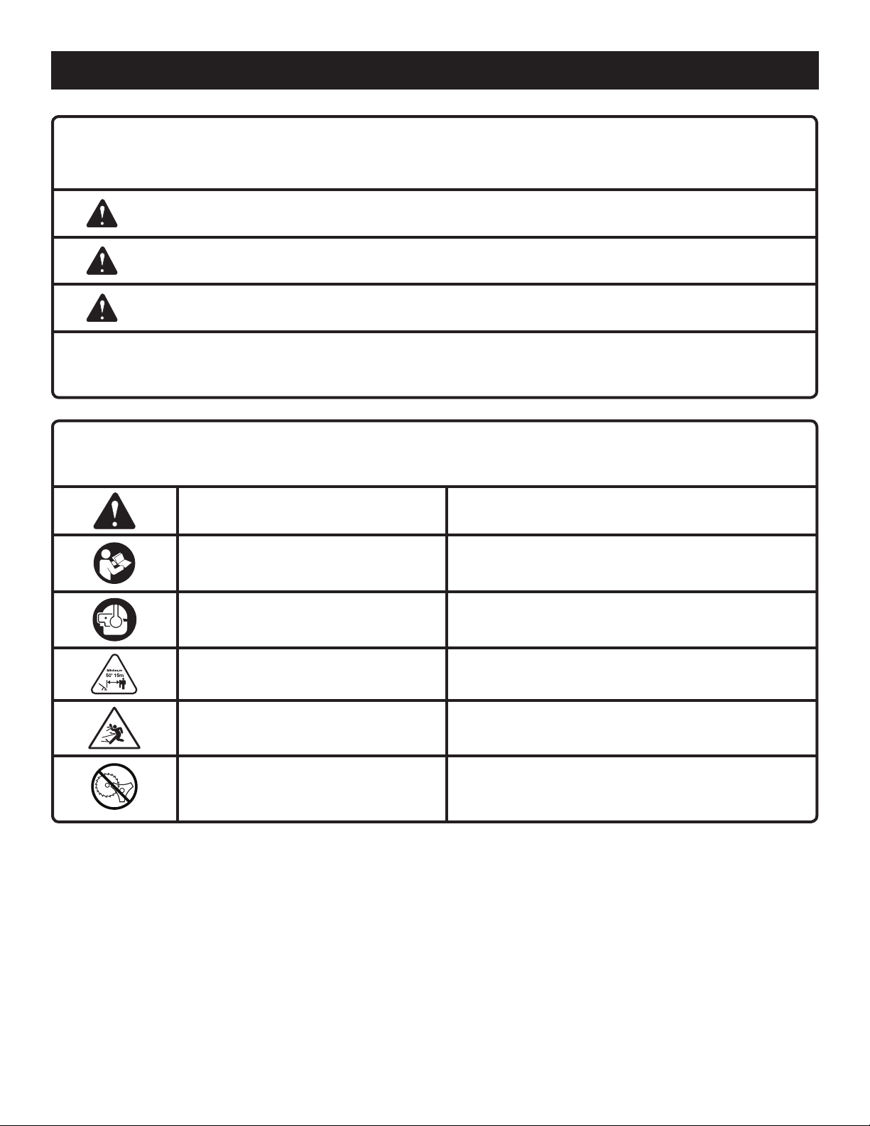
SÍMBOLOS
Las siguientes palabras de señalización y sus significados tienen el objeto de explicar los niveles de riesgo relacionados
con este producto.
SÍMBOLO SEÑAL SIGNIFICADO
PELIGRO:
ADVERTENCIA:
PRECAUCIÓN:
AVISO:
Es posible que se empleen en este producto algunos de los siguientes símbolos. Le suplicamos estudiarlos y aprender
su significado para mayor seguridad al manejar este producto.
Indica una situación peligrosa inminente, la cual, si no se evita, causará la muerte
o lesiones serias.
Indica una situación peligrosa posible, la cual, si no se evita, podría causar la
muerte o lesiones serias.
Indica una situación potencialmente peligrosa la cual, si no se evita, puede
causar lesiones leves o moderadas.
(Sin el símbolo de alerta de seguridad) Indica información importante no
relacionada con ningún peligro de lesiones, como una situación que puede
ocasionar daños físicos.
SYMBOLO NOMBRE EXPLICATIÓN
Símbolo de alerta de seguridad Indica un peligro posible de lesiones personales.
Para reducir el riesgo de lesiones, el usuario debe leer y
Lea el manual del operador
Póngase protección para los ojos y
los oídos
comprender el manual del operador antes de usar este
producto.
Siempre póngase protección ocular con la marca de
cumplimiento de la norma ANSI Z87.1 junto con protección
para los oídos.
Mantenga alejadas a las personas
presentes
Rebote
No instale hoja de corte
Mantenga alejados a los observadores a un mínimo de
15 m (50 pies) de distancia.
Cualquier objeto lanzado puede rebotar y producir lesiones
personales o daños físicos.
No instale ni utilice ningún tipo de hoja de corte en ningún
producto con este símbolo.
5 — Español
Page 34

CARACTERÍSTICAS
ESPECIFICACIONES DEL PRODUCTO
Peso - (sin combustible) ........................... 10,2 kg (22,6 lb.)
Anchura del corte del hilo ................... 406,4 mm (16 pulg.)
Cilindrada del motor ................................................... 30 cc
Volumen de lubricante de motor ................................ 65 ml
Volumen de combustible .......................................... 350 ml
Diámetro del hilo .................................................................
.................... 2,4 mm a 2,7 mm (0,095 pulg. a 0,105 pulg.)
FAMILIARÍCESE CON SU RECORTADORA CON
RUEDAS
Vea la figura 1.
Para usar este producto con la debida seguridad se debe
comprender la información indicada en la herramienta
misma y en este manual, y se debe comprender también
el trabajo que intenta realizar. Antes de usar este producto,
familiarícese con todas las características de funcionamiento
y normas de seguridad del mismo.
EJE CURVO
El diseño curvo del eje de la recortadora le permite recortar
áreas perimetrales fácilmente.
ARMADO
DESEMPAQUETADO
Embarcamos este producto completamente armado.
Extraiga cuidadosamente de la caja la producto y los
accesorios. Asegúrese de que estén presentes todos los
artículos enumerados en la lista de empaquetado.
NOTA: Tenga cuidado de no doblar el cable del acelerador
al desempaquetar la unidad.
ADVERTENCIA:
No utilice este producto si alguna pieza incluida en la lista
de empaquetado ya está ensamblada al producto cuando
lo desempaqueta. El fabricante no ensambla las piezas
de esta lista en el producto. Éstas deben ser instaladas
por el usuario. El uso de un producto que puede haber
sido ensamblado de forma inadecuada podría causar
lesiones personales graves.
Inspeccione cuidadosamente la producto para asegurarse
de que no haya sufrido ninguna rotura o daño durante el
transporte.
No deseche el material de empaquetado hasta que haya
inspeccionado cuidadosamente la producto y la haya
utilizado satisfactoriamente.
Si hay piezas dañadas o faltantes, le suplicamos llamar
al 1-800-860-4050, donde le brindaremos asistencia.
DISEÑO ERGONÓMICO
El diseño de la recortadora permite un fácil manejo de la
misma. El diseño brinda una sujeción cómoda y fácil para
el trabajo en diferentes posiciones y ángulos.
DEFLECTOR DE PASTO
La recortadora incorpora un deflector de pasto que ayuda
a proteger al operador de los desechos lanzados por la
herramienta.
TAPA DE ACEITE/VARILLA PARA MEDIR EL
ACEITE
Retire la tapa de aceite para revisar el nivel y añadir lubricante
cuando sea necesario.
LISTA DE EMPAQUETADO
Conjunto de ruedas/cabezal motor de la recortadora
Conjunto de eje/cabezal del hilo Pro Cut II
Conjunto del mango
Deflector de pasto
Soporte de línea
Hilo de 2,7 mm (0,105 pulg.) (20 piezas)
Embudo de papel
Botella de lubricante para motor de cuatro tiempos
Manual del operador
™
ADVERTENCIA:
Si faltan piezas, no utilice este producto sin haber
reemplazado todas las piezas faltantes. Usar este
producto con partes dañadas o faltantes puede causar
lesiones serias al operador.
ADVERTENCIA:
No intente modificar este producto ni hacer accesorios
no recomendados para la misma. Cualquier alteración o
modificación constituye maltrato el cual puede causar
una condición peligrosa, y como consecuencia posibles
lesiones corporales serias.
6 — Español
Page 35

ARMADO
ADVERTENCIA:
Para evitar un arranque accidental que podría causar lesiones
corporales graves, siempre desconecte el cable de la bujía
del motor de la bujía misma al ensamblar las piezas.
ADVERTENCIA:
Asegúrese de que esté bien apretada las perillas antes de
utilizar el equipo; verifique periódicamente el apriete de la
misma durante el uso para evitar lesiones corporales graves.
INSTALACIÓN DEL CONJUNTO DE EJE/CABEZAL
DEL HILO PRO CUT II™ AL CONJUNTO DE RUEDAS/
CABEZAL MOTOR DE LA RECORTADORA
Vea la figura 2.
Ubique las partes inferior y superior de la barra del mango
en sus respectivos lugares. Asegúrese de que el cable del
acelerador y el gatillo del acelerador se encuentren en el
lado derecho, tal como se indica en la figura.
Introduzca el perno de la pasador plástico, a continuación,
a través de los orificios.
NOTA: No deje que se comprima el cable del acelerador
cuando instale la barra del mango.
Alinee los agujeros del clip con los agujeros del parte
superior de la barra del mango y los agujeros del parte
inferior de la barra del mango.
Introduzca el perno como se muestra.
Enrosque la perilla de la barra del mango sobre el perno y
apriétela firmemente. Repita con el otro costado.
MONTAJE DEL DEFLECTOR DE PASTO
Vea la figura 5.
ADVERTENCIA:
Nunca instalar, quitar o ajustar cualquier accesorio mientras
el motor está en marcha o el cabezal de corte se mueve. Si
no se detiene el motor y el cabezal de corte puede causar
lesiones personales graves.
El conjunto de eje/cabezal del hilo Pro Cut II™ se conecta al
conjunto de ruedas/cabezal motor de la recortadora mediante
un dispositivo acoplador.
Afloje la perilla en el acoplador del eje del cabezal de potencia
y retire la tapa extrema del conjunto de eje/cabezal del hilo.
Oprima el botón situado en el eje de la cabezal del hilo.
Alinee el botón con el hueco guía situado en el acoplador
del cabezal motor, y con un movimiento de deslizamiento
una los dos ejes. Gire el eje de la cabezal del hilo hasta que
el botón quede asegurado en el orificio de posicionamiento.
NOTA: Si el botón no brota completamente en el orificio
de posicionamiento, significa que los ejes no están bien
asegurados en su lugar. Gire levemente los ejes de un lado
a otro hasta que el botón quede asegurado en su lugar.
Apriete firmemente la perilla.
INSTALACIÓN DE LA PARTE INFERIOR DE LA
BARRA DEL MANGO
Vea la figura 3.
Retire las dos perillas y los dos pernos de la barra del mango
inferior de la bolsa de piezas de ferretería.
Coloque la barra del mango inferior en las aberturas del
conjunto de ruedas/cabezal motor de la recortadora, como
se muestra.
NOTA: No deje que se comprima el cable del acelerador
cuando instale la barra del mango.
Introduzca los pernos a través de los orificios de la barra
del mango y del bastidor.
Instale las perillas de la barra del mango inferior y apriete
firmemente.
INSTALACIÓN DE LA PARTE SUPERIOR DE LA
BARRA DEL MANGO
Vea la figura 4.
Tome dos perillas y dos pernos para la barra del mango de
la bolsa de herrajes.
ADVERTENCIA:
La cuchilla de cortar el hilo del deflector de pasto está
afilada. Evite tocar la cuchilla. Si no evita tal contacto puede
originarse lesiones corporales serias.
Retire el tornillo de mariposa del deflector de pasto.
Introduzca la orejeta del soporte de montaje en la ranura del
deflector de pasto.
Alinee el orificio del tornillo en el soporte de montaje con
orificio del tornillo del deflector de pasto.
Introduzca el tornillo de mariposa a través del soporte de
montaje y en el deflector de pasto.
Apriete firmemente el tornillo.
INSTALACIÓN DEL HILO EN EL CABEZAL DEL
HILO PRO CUT II
Vea la figura 6.
Use hilo monofilar de entre 2,4 mm (0,095 pulg.) y 2,7 mm
(0,105 pulg.) de diámetro. Use hilo de repuesto de la calidad
para obtener el mejor desempeño.
Apague el motor y desconecte el cable de la bujía.
Tome dos de los tramos precortados del hilo de la recortadora
suministrados o corte dos piezas de hilo de la recortadora
en tramos de 254 mm (10 pulg.).
Introduzca los hilos en las ranuras situadas a los lados
del cabezal del hilo. El hilo debe introducirse hasta que
sobresalgan aproximadamente 25,4 mm (1 pulg.) de los
orificios en la parte superior del cabezal del hilo.
Tire del hilo viejo para retirarlo a través de los orificios situados
en la parte superior del cabezal del hilo.
™
ADVERTENCIA:
No retire los tornillos ni desarme el cabezal del hilo. Si se
abre el cabezal, los resortes de compresión pueden salir
lanzados hacia el operador y provocar lesiones serias.
INSTALACIÓN DEL SOPORTE DE LÍNEA
Vea la figura 7.
El soporte de línea queda fijo en la barra del mango inferior en
el lado opuesto del cable del acelerador y se usa para sostener
piezas precortadas de la recortadora.
7 — Español
Page 36

ARMADO
NOTA: No instale el soporte en lugares donde pueda interferir
con el cable del acelerador o donde pueda cubrir cualquiera
de los íconos o etiquetas de advertencia.
FUNCIONAMIENTO
ADVERTENCIA:
No permita que su familarización con este producto le vuelva
descuidado. Tenga presente que un descuido de un instante
es suficiente para infligir una lesión grave.
ADVERTENCIA:
Siempre póngase protección ocular con protectores
laterales con la marca de cumplimiento de la norma ANSI
Z87.1 junto con protección auditiva. La inobservancia de
esta advertencia puede causar el lanzamiento de objetos
hacia los ojos y otras lesiones graves.
ADVERTENCIA:
No utilice ningún aditamento o accesorio no recomendado
por el fabricante de este producto. El empleo de aditamentos
o accesorios no recomendandos podría causar lesiones
serias.
ADVERTENCIA:
El uso de este equipo podría producir chispas propensas a
iniciar incendios cerca de vegetación seca. Es posible que
se necesite un parachispas. El operador debe ponerse en
contacto con las agencias contra incendios locales para
conocer las leyes y regulaciones relacionadas con los
requisitos de prevención de incendios.
COMBUSTIBLES OXIGENADOS
AVISO:
No utilice combustibles E15 o E85 (ni combustibles que
contengan más de 10 % de etanol) con este producto.
Esto constituye una violación a la ley federal, dañará la
unidad y anulará la garantía.
No están cubiertos en la garantía los problemas de
desempeño o daños al sistema de combustible producidos
por el uso de un combustible oxigenado con un contenido
superior a los porcentajes de alcohol o compuesto de éter
señalados abajo.
Etanol. Las gasolinas con un contenido de 10% de etanol por
volumen (comunmente conocida como E10) es aceptables. Las
gasolinas E15 y E85 no lo son.
Para instalar la línea, quite la tapa superior, inserte la línea
en el soporte y reemplace la tapa. Para sacar la línea de
funcionamiento, retírela del área abierta en frente del soporte.
ABASTECIMIENTO Y REABASTECIMIENTO DE
COMBUSTIBLE DE LA RECORTADORA
ADVERTENCIA:
La gasolina y sus vapores son altamente inflamables y explosivos. Maneje con cuidado el producto para evitar lesiones personales graves y daños a la propiedad. Manténgalo
alejado de fuentes de ignición y llamas abiertas, utilícelo al
aire libre únicamente, no fume mientras mezcle la gasolina
y el lubricante y limpie los derrames inmediatamente.
Limpie la superficie alrededor de la tapa del tanque de
combustible para evitar toda contaminación.
Afloje lentamente la tapa del tanque de combustible. Coloque
la tapa en una superficie limpia.
Vierta cuidadosamente el combustible en el tanque. Evite
los derrames.
Antes de volver a colocar la tapa del tanque de combustible,
limpie e inspeccione la junta.
Vuelva a colocar inmediatamente la tapa del tanque de
combustible y apriételo con la mano. Limpie todo derrame
de combustible.
NOTA: Es normal que salga humo de un motor nuevo después
de usarlo por primera vez.
ADVERTENCIA:
Siempre apague el motor antes de abastecer el combustible.
Nunca agregue combustible a una máquina con el motor en
marcha o caliente. Aléjese por lo menos 30 pies (9 metros) del
sitio de reabastecimiento de combustible antes de encender
el motor. ¡No fume! La inobservancia de esta advertencia
puede causar lesiones serias.
ABASTECIMIENTO Y VERIFICACIÓN DE
LUBRICANTE
Vea la figura 8.
AVISO:
Si se intenta arrancar el motor antes de haberse abastecido
debidamente de aceite podría descomponerse el equipo.
El lubricante de motor empleado es un factor de gran importancia en el rendimiento y vida de servicio del motor. Esta unidad
se envía con un lubricante para motor 20W50 para ayudar en
el período de asentamiento. Para un mejor rendimiento, se
recomienda seguir usando el lubricante para motor 20W50,
sin embargo, todos los lubricantes SAE 30, 10W30 ó 10W40
son aceptables para ser usados en estos productos. Siempre
8 — Español
Page 37

FUNCIONAMIENTO
utilice lubricante para motor de cuatro tiempos que satisfaga
o sobrepase los requisitos SJ de clasificación de servicio API.
Verifique el nivel de lubricante antes de cada uso.
NOTA: El lubricante sin detergente o para motor de dos tiempos
daña el motor, por lo cual no debe usarse.
Para añadir lubricante para motor:
Retire la tapa y el sello de la botella de lubricante provista.
Desenrosque la tapa de relleno de aceite/varilla medidora
de aceite y retírela. El nivel del lubricante debe estar entre
los 2 cuadrados de la varilla de medición.
Si el nivel es bajo, agregue lubricante para motor hasta que
el nivel del líquido llegue a la porción superior de la varilla
de medición.
Vuelva a colocar la tapa de relleno de aceite/varilla medidora
de aceite y asegúrelos.
Para verificar el nivel de lubricante para motor:
Coloque la unidad sobre una superficie plana.
Limpie la varilla de nivel y vuelva a asentarla en el agujero;
no la enrosque.
Retire de nuevo la varilla medidora de lubricante y verifique
el nivel de lubricante. El nivel de aceite siempre debe estar
dentro del área cubierta con rayas entrecruzadas de la varilla
medidora.
Si está bajo el nivel, abastezca de lubricante el motor hasta
que el nivel del fluido alcance la parte superior del área
cubierta con rayas entrecruzadas de la varilla.
Vuelva a colocar la tapa de relleno de aceite/varilla medidora
de aceite y asegúrela.
AVISO:
No lo llene excesivamente. Llenar excesivamente el cárter
puede producir humo en exceso, pérdida de aceite y daños
en el motor.
ARRANQUE Y APAGADO
Vea las figuras 9 a 13.
Para el arranque debe colocarse la recortadora en una superficie
plana y despejada.
Para arrancar con el motor frío:
Presione lentamente 10 veces la bomba de cebado.
NOTA: Luego de la 7ª vez que oprima, se debe ver el com-
bustible en la bomba de cebado. Si esto no sucede, continúe
presionando el cebador hasta que vea combustible en la
bomba.
Coloque la palanca del anegador en la posición FULL CHOKE
(anegación máxima).
NOTA: No oprima el gatillo del acelerador.
Tire del mango del arrancador hasta que empiece a funcionar
el motor.
NOTA: Si después de haber tirado tres veces, el motor no
arranca y :
la temperatura exterior es 15 ºC (60°F) o menor, deje
la palanca del anegador en la posición FULL CHOKE
(anegación máxima) y continúe tirando del mango del
arrancador hasta que empiece a funcionar el motor.
la temperatura exterior es mayor a 15 ºC (60°F) mueva
la palanca del anegador en la posición HALF CHOKE
(anegación media) y continúe tirando del mango del arrancador hasta que empiece a funcionar el motor.
Permita que el motor funcione 10 segundos y después ponga
la palanca del anegador en la posición RUN (funcionamiento).
Para arrancar con el motor caliente:
Presione lentamente 10 veces la bomba de cebado.
Después ponga la palanca del anegador en la posición RUN
(funcionamiento).
Tire del mango de arranque hasta que el motor se ponga
en marcha. No apriete el gatillo del acelerador.
Para apagar el motor:
Para apagar el motor, coloque el interruptor de STOP en la
posición de apagado “ ”.
SI NECESITA ASISTENCIA PARA EL ARRANQUE ESTE
PRODUCTO:
No devuelva este producto a la tienda donde fue adquirido. Por
favor llame al Departamento de Atención al Cliente para todo
problema que pueda tener.
Si necesita asistencia llame al: 1-800-860-4050.
SUGERENCIAS PARA CORTAR
Vea la figura 14.
Sujete firmemente la unidad con ambas manos durante la
operación.
Si la hierba se enrolla alrededor del cabezal del hilo, APAGUE
EL MOTOR, desconecte el cable de la bujía y desprenda la
hierba.
Use la punta del hilo para efectuar el recorte; no fuerce el
cabezal del hilo hacia la hierba sin cortar.
Las cercas de alambre y de estacas causa desgaste adicio-
nal en el hilo, incluso la ruptura. Los muros de piedra y de
ladrillo, los cordones y la madera pueden gastar rápidamente
el hilo.
Evite el contacto con árboles y los arbustos. La corteza de
los árboles, las molduras de madera, los revestimientos
de las paredes y los postes de las cercas pueden resultar
dañados fácilmente por el hilo.
TRANSPORTE LA UNIDAD
Ponga el interruptor del apagado en APAGADO (O).
Asegúrese de que estén fríos el motor y el escape de la
unidad.
Mantenga nivelada la unidad para evitar derramar el com-
bustible.
9 — Español
Page 38

MANTENIMIENTO
ADVERTENCIA:
Al dar servicio a la unidad, sólo utilice piezas de repuesto
idénticas. El empleo de piezas diferentes puede causar un
peligro o dañar el producto.
ADVERTENCIA:
Siempre póngase protección ocular con la marca de
cumplimiento de la norma ANSI Z87.1 junto con protección
para los oídos. La inobservancia de esta advertencia puede
permitir que los objetos lanzados hacia los ojos y otros
provocarle lesiones graves.
ADVERTENCIA:
Antes de inspeccionar, limpiar o dar mantenimiento a la
máquina, apague el motor, espere hasta que se detengan
todas las piezas en movimiento, desconecte el cable de
la bujía y apártelo de la bujía. El incumplimiento de estas
instrucciones puede provocar lesiones personales graves
o daños materiales.
MANTENIMIENTO GENERAL
Evite el empleo de solventes al limpiar piezas de plástico. La
mayoría de los plásticos son susceptibles a diferentes tipos
de solventes comerciales y pueden resultar dañados. Utilice
paños limpios para eliminar la suciedad, el polvo, el lubricante,
la grasa, etc.
Para efectuar la limpieza:
Apague la recortadora y desconecte el cable de la bujía.
Deje enfriar la unidad, si es necesario.
Con un paño seco o un cepillo de nylon, elimine la tierra y
la basura de la pantalla.
AJUSTE DE LA MARCHA LENTA
Vea la figura 17.
ADVERTENCIA:
El cabezal de corte se moverá cuando se ajuste la velocidad
de marcha lenta. Utilice todas las prendas de protección y
no permita la presencia de personas ajenas a la operación,
niños ni mascotas a una distancia mínima de 15 metros (50
pies). Realice los ajustes con la unidad apoyada a mano
de modo que el cabezal de corte no entre en contacto con
el piso ni con cualquier objeto. Mantenga todas las partes
del cuerpo alejadas del cabezal de corte y el silenciador.
El incumplimiento de estas instrucciones podría causar
lesiones personales de gravedad.
Si el accesorio del corte avanza estando el motor en marcha
lenta, se necesita ajustar el tornillo de marcha lenta del motor.
Gire el tornillo de velocidad de marcha lenta en el sentido
contrario a las manecillas del reloj para reducir las RPM y
que se detenga el movimiento del accesorio del corte. Si el
accesorio del corte aún se mueve al estar el motor en marcha
lenta, contacte a un representante de servicio para el ajuste y
suspenda el uso de la misma hasta que se efectúe la reparación.
ADVERTENCIA:
No permita en ningún momento que fluidos para frenos,
gasolina, productos a base de petróleo, lubricantes
penetrantes, etc., lleguen a tocar las piezas de plástico.
Los productos químicos pueden dañar, debilitar o destruir
el plástico, lo cual puede causar lesiones serias.
A menudo, usted puede efectuar los ajustes y reparaciones
descritos aquí. Para otro tipo de reparaciones, lleve la
recortadora a un establecimiento de servicio autorizado.
ACCESO AL CABEZAL DEL HILO
Vea la figura 15.
Para desajustar la bola para cortar, gírela EN SENTIDO
HORARIO con el perno de cabeza hexagonal.
Retire del eje la bola para cortar con el perno de cabeza
hexagonal.
Para volver a colocar la bola para cortar:
Deslice la bola para cortar con el perno de cabeza hexagonal
sobre el eje.
Gire EN SENTIDO ANTI HORARIO para ajustar.
LIMPIEZA DE LA PANTALLA DE ENTRADA DE
AIRE
Vea la figura 16.
Si la pantalla de entrada de aire se obstruye o ensucia, disminuye
la circulación de aire y el rendimiento del motor se ve afectado.
ADVERTENCIA:
El accesorio del corte nunca debe girar en marcha lenta.
Gire a la izquierda el tornillo de marcha lenta para reducir
dicha marcha y así detener el accesorio de corte, o
comuníquese con un representante de servicio para que
la ajusten, y suspenda el uso de la unidad hasta que se
efectúe la reparación. Si el accesorio del corte se mueve
al estar el motor en marcha lenta, pueden resultar lesiones
corporales serias.
LIMPIEZA DEL FILTRO DE AIRE
Vea la figura 18.
Cambie el filtro de aire según señala el calendario de
mantenimiento.
Para limpiar el filtro de aire:
Afloje la tapa del filtro de aire girando la perilla hacia la
izquierda.
Retire la tapa del filtro de aire.
Retire el filtro de aire.
Golpee levemente o limpie con un chorro de aire toda
partícula de polvo del filtro.
Vuelva a instalar el filtro.
NOTA: Asegúrese de que el filtro esté asentado correctamente
en el interior de la tapa. Si se instala de forma incorrecta el
filtro el polvo entra en el motor y causa un rápido desgaste
del mismo.
Vuelva a instalar la tapa.
10 — Español
Page 39

MANTENIMIENTO
Apriete firmemente la perilla.
NOTA: Para lograr un desempeño óptimo de la unidad, cada
año debe reemplazarse el filtro de aire.
TAPA DEL TANQUE DE COMBUSTIBLE,
PÉRDIDAS EN EL TANQUE Y EN LAS LÍNEAS
DE COMBUSTIBLE
ADVERTENCIA:
Revise la herramienta para ver si tiene fugas de combustible.
Una tapa del tanque de combustible, el tanque, o la línea,
están con fugas constituye un riesgo de incendio y debe
reemplazarse inmediatamente. Si encuentra fugas, corrija
el problema antes de utilizar la herramienta. De lo contrario
puede producirse un incendio, con el consiguiente riesgo
de lesiones serias.
La tapa del tanque de combustible contiene un filtro que no
necesita mantenimiento y una válvula de retención. Un filtro de
combustible obstruido puede causar un desempeño deficiente
del motor. Si mejora el desempeño al aflojar la tapa del tanque
de combustible, es posible que esté defectuosa la válvula de
retención o quizá esté obstruido el filtro. Reemplace la tapa
del tanque de combustible si es necesario.
REEMPLAZO DE LA BUJÍA
Vea la figura 19.
La cultivadora requiere una bujía Champion RY4C con una
separación interelectródica de 0,63 mm (0.025 pulg.). Utilice
un repuesto idéntico y cámbielo anualmente.
Quite los tornillos de la parte trasera de la carcasa del motor.
Esto permitirá que la carcasa del motor quede descubierta
tal como se muestra.
Retire la funda de la bujía.
Afloje la bujía; para ello, gírela hacia la izquierda con una
llave de cubo.
Retire la bujía.
Enrosque la nueva bujía con la mano, girándola hacia la
derecha.
Apriétela con una llave de cubo a 19,2 Nm (170 lb-pulg)
como mínimo, y a 21,5 Nm (190 lb-pulg) como máximo. No
efectúe un apriete excesivo
Asegure la carcasa del motor en su lugar y regrese el tornillo.
Asegúrese de que la carcasa esté estable.
AVISO:
Tenga cuidado de no cruzar el hilo de la bujía. Cruz roscando
dañará seriamente el producto.
CAMBIO DEL LUBRICANTE PARA MOTOR
Vea la figura 20.
ADVERTENCIA:
No cambie el lubricante para motor cuando esté caliente.
El contacto accidental con lubricante para motor caliente
podría ocasionarle graves quemaduras.
Para lograr un desempeño óptimo, el lubricante para motor
debe cambiarse cada 25 horas de uso.
Detenga el motor y desconecte el cable de la bujía. Deje
enfriar el motor completamente antes de comenzar.
Retire la tapa de relleno de aceite/varilla medidora de aceite.
Incline la unidad hacia atrás de manera que los mangos se
apoyen sobre el suelo y deje drenar el lubricante del agujero
de llenado de aceite a un recipiente aprobado.
NOTA: Drene el lubricante mientras el motor esté tibio, no
caliente. El lubricante tibio drena rápidamente y casi por
completo.
Vuelva la unidad en posición vertical y abastezca de lubricante
siguiendo las instrucciones que aparecen en la sección
anterior de este manual: Abastecimiento y verificación
del lubricante para motor.
NOTA: El lubricante usado debe desecharse en un vertedero
aprobado. Consulte su vendedor local para obtener más
información.
AJUSTE DE LA APERTURA DEL ÁRBOL DE
LEVAS DEL BALANCÍN
Vea las figuras 21 a 23.
Inspeccione la apertura del árbol de levas del balancín cada 25
horas de funcionamiento. Debe realizar esta tarea en un lugar
limpio y sin polvo.
NOTA: Este procedimiento requiere un desarmado parcial del
motor. Si no está seguro de estar capacitado para realizar esta
operación, lleve la unidad a un centro de servicio autorizado.
Apague el motor y desconecte el cable de la bujía. Deje
enfriar el motor completamente antes de comenzar.
Quite los tornillos de la tapa superior del motor. Quite la tapa
del motor y déjela a un lado.
Usando un destornillador Torx, quite el tornillo de la tapa
del balancín. Quite la tapa y déjela a un lado.
Coloque el árbol de levas tirando del mango del arrancador
retráctil hasta que el orificio profundo del engranaje del árbol
de levas quede en la posición de las 6 en punto.
Coloque el calibrador de separaciones debajo de cada
balancín y mida el espacio como se muestra. Este espacio
debe medir entre 0,15 mm (0,006 pulg.). y 0,20 mm
(0,008 pulg.) en ambos balancines.
NOTA: Use un calibrador de separaciones estándar para
automóviles. El calibrador de separaciones de 0,15 mm
(0,006 pulg.) debe deslizarse entre el balancín y el vástago
de la válvula con una pequeña resistencia pero sin atascarse.
El calibrador de separaciones de 0,20 mm (0,008 pulg.) no
debe deslizarse entre los balancines y los lóbulos de leva,
sino que debe mantenerse fijo.
Si la apertura de la válvula no es entre 0,15 mm (0,006 pulg.)
y 0,20 mm (0,008 pulg.), la apertura debe ajustarse como
se describe a continuación:
Mientras sostiene con una mano una llave en las partes
planas de la tuerca de ajuste, afloje la tuerca de retención
con una segunda llave. Tenga cuidado de que el vástago
no se afloje.
11 — Español
Page 40

MANTENIMIENTO
Gire la tuerca de ajuste hasta que toque el calibrador de
separaciones. Una vez que el espacio esté correctamente
configurado, sostenga la llave en las partes planas de
la tuerca de ajuste y reajuste firmemente la tuerca de
retención.
Si es necesario, ajuste el segundo balancín.
Vuelva a colocar la tapa de los balancines y ajuste los tornillos
firmemente.
Vuelva a colocar la tapa superior del motor y ajuste los
tornillos firmemente.
ADVERTENCIA:
Asegúrese de que todas las cubiertas y todas las piezas del
motor estén colocadas correctamente antes de arrancar el
motor. Si no vuelve a armar el motor correctamente, puede
ocasionar lesiones graves y daños a los bienes.
ALMACENAMIENTO DE LA PRODUCTO
Limpie todo material extraño de la producto. Almacene la
unidad en un espacio bien ventilado inaccesible a los niños.
Evite que la unidad entre en contacto con agentes corrosivos
como las sustancias químicas para el jardín y las sales para
derretir el hielo.
Cumpla todos los reglamentos federales y municipales para
el almacenamiento y manejo seguro de la gasolina.
Al almacenar 1 mes o más:
Drene todo el combustible del tanque en un recipiente de
uso aprobado para gasolina. Accione el motor hasta que se
apague.
OPERACIÓN DEL MOTOR A ALTITUDES
ELEVADAS
Lleve este equipo a un centro de servicio técnico autorizado
para que ajusten este motor en caso de que se lo deba hacer
funcionar a más de 600 metros (2000 pies) de altura. De no
hacerlo, el rendimiento del motor podría verse afectado y
podría aumentar el nivel de emisiones contaminantes. Un motor
ajustado para altitudes elevadas no puede hacerse funcionar
a una altura inferior a los 600 metros (2000 pies). De hacerlo,
el motor se sobrecalentará y sufrirá graves daños. Lleve todo
motor que haya sido modificado para funcionar a altitudes
elevadas a un centro de servicio técnico autorizado para que
restauren las condiciones de las especificaciones de fábrica
originales antes de hacerlo funcionar a menos de 600 metros
(2000 pies) de altura.
PROGRAMA DE MANTENIMIENTO
Inspeccionar para danõs Limpiar Reemplazar cada Reemplácelo
Pieza de cada vez antes cada 5 horas 25 horas de uso cada
mantenimiento de usar la unidad de uso o cada año 50 Horas
* CONJUNTO DEL FILTRO DE AIRE
incluye:
Filtro .........................................................................................................X
* CONJUNTO DEL CARBURADOR
incluye:
Juntas .........................................................X
* CONJUNTO DEL TANQUE DE COMBUSTIBLE
incluye:
Conductos de combustible ......................... X
Tapa del tanque de combustible .................X
Filtro de combustible ........................................................................................................................... X
* CONJUNTO DEL ENCENDIDO
incluye:
Bujía ..................................................................................................................................................... X
* AVISO: EL USO DE COMPONENTES DE CONTROL DE EMISIONES QUE NO SEAN LOS DISEÑADO PARA ESTA UNIDAD INFRINGE LA
LEGISLACIÓN FEDERAL.
¿NECESITA AYUDA?
LLÁMENOS PRIMERO
LLAME AL
1-800-860-4050
www.ryobitools.com
Si tiene preguntas sobre el funcionamiento o el mantenimiento este
producto,llame al teléfono de atención al consumidor de Ryobi®!
La recortadora ha sido probada enteramente antes de embarcarse para
asegurar la satisfacción del consumidor.
12 — Español
Page 41

SOLUCIÓN DE PROBLEMAS
SI CON ESTAS SOLUCIONES NO SE RESUELVE EL PROBLEMA, COMUNÍQUESE CON EL CONCESIONARIO DE
SERVICIO AUTORIZADO DE SU PREFERENCIA.
PROBLEMA CAUSA POSIBLE SOLUCIÓN
El motor no arranca No hay chispa.
No hay combustible.
Está ahogado el motor.
El motor no alcanza la máxima
velocidad y emite demasiado
humo
Está sucio el filtro de aire.
Está sucia la pantalla parachispas.
Falló la bujía.
Limpie o reemplace la bujía, según sea necesario.
Reajuste la separación interelectródica de la
bujía. Consulte la sección Reemplazo de la
bujía más arriba en este manual.
Presione la bomba de cebado hasta que se
llene de combustible la misma. Si no se llena la
bomba, significa que está obstruido el sistema
de conducción de combustible. Comuníquese
con un establecimiento de servicio. Si se llena la
bomba, es posible que esté ahogado el motor,
prosiga con el siguiente punto.
Coloque la palanca del anegador en la posición
START (arranque). Oprima el gatillo y tire
de la cuerda hasta que el motor arranque y
funcione.
NOTA: Dependiendo de la intensidad del
ahogamiento, pueden requerirse numerosos
tirones de la cuerda.
Limpie el filtro de aire. Consulte la sección
Limpieza del filtro de aire previamente en
este manual.
Comuníquese con un establecimiento de
servicio.
Limpie o reemplace la bujía, según sea necesario.
Reajuste la separación interelectródica de la
bujía. Consulte la sección Reemplazo de la
bujía más arriba en este manual.
El motor arranca, marcha y acelera
pero no funciona a velocidad de
marcha en vacío (ralentí)
Es difícil girar el retén del carrete La rosca del tornillo está sucia o dañada. Limpie las roscas y lubríquelas con grasa - si no
El pasto se enreda alrededor del
alojamiento del eje de impulsión y
del cabezal del hilo
El motor emite demasiado humo Hay demasiado aceite en el cárter. Drene el lubricante y vuelva a llenar con la
No se puede tirar de la cuerda del
motor
El tornillo de marcha lenta del carburador
necesita ajuste.
Se está cortando la hierba alta a nivel del
suelo.
Se está utilizando la recortadora con el
anegador parcialmente abierto.
Ha entrado aceite en la cámara de
combustión.
Gire a la derecha el tornillo de marcha lenta
para aumentar la velocidad de marcha en vacío
(ralentí). Vea la figura 16.
hay mejoría, reemplace el retén del carrete.
Corte la hierba alta de arriba hacia abajo para
evitar que se enrede en la unidad.
Accione la recortadora a la máxima
aceleración.
cantidad correcta de lubricante para motor
10W-30. Consulte Cómo agregar/verificar el
lubricante para motor en la sección Operación
de este manual.
Esto generalmente se debe a que la unidad ha
estado guardada durante un tiempo extendido
con el motor en posición invertida. Retire y limpie
la bujía. Drene el aceite del orificio de la bujía,
luego vuelva a colocarla.
13 — Español
Page 42

GARANTÍA
DECLARACIÓN DE LA GARANTÍA LIMITADA
Techtronic Industries North America, Inc. garantiza al
comprador original al menudeo que este producto de la marca
RYOBI® carece de defectos en los materiales y en la mano
de obra, y acuerda reparar o remplazar, a la sola discreción
de Techtronic Industries North America, Inc., cualquier
producto defectuoso, sin cargo alguno al comprador, dentro
de los siguientes períodos de tiempo a partir de la fecha de
compra.
Tres años si los productos se emplean para uso personal,
familiar o casero;
90 días si el producto se emplea para cualquier otro
propósito, como el uso comercial o el de alquiler.
Esta garantía se otorga solamente al comprador original al
menudeo, y comienza en la fecha de la compra original al
menudeo.
Cualquier parte de este producto Techtronic Industries
North America, Inc. que, a juicio razonable de la compañía,
tenga defectos en los materiales o en la mano de obra, será
reparado o reemplazado por un centro de servicio autorizado
de herramientas para uso en el exterior de la marca RYOBI®,
sin cargo alguno al comprador por concepto de piezas y mano
de obra (Centro de Servicio Autorizado Ryobi).
El producto, incluida toda pieza defectuosa, debe enviarse a
un centro de servicio autorizado Ryobi dentro del período de
la garantía. El gasto de enviar el producto al centro de servicio
para cualquier trabajo cubierto por la garantía, así como el
gasto de devolverlo al propietario después de la reparación,
correrán por cuenta del propietario. La responsabilidad de
Techtronic Industries North America, Inc. con respecto a
todo reclamo se limita a las reparaciones o remplazo del
producto, y ningún reclamo de incumplimiento de la garantía
será causante de la cancelación o rescisión del contrato de
venta de ninguna herramienta de uso en el exterior de la
marca RYOBI®. En el establecimiento se requerirá el recibo
de compra para respaldar cualquier reclamo al amparo de
la garantía. Todo trabajo cubierto en la garantía debe ser
realizado por un concesionario de servicio autorizado.
Esta garantía se limita a noventa (90) días a partir de la fecha
original de la compra de cualquier herramienta de uso en
el exterior de la marca RYOBI® empleada para propósitos
comerciales o de alquiler, o cualquier otro propósito
generador de ingresos.
Esta garantía no cubre ningún producto que haya sido
sujeto a un uso indebido, maltrato, negligencia o accidente,
o que haya sido utilizado de cualquier forma contraria a las
instrucciones de manejo especificadas en el manual del
operador del producto. Esta garantía no aplica a ningún daño
en el producto que resulte de un mantenimiento indebido
ni a ningún producto que haya sido alterado o modificado.
La garantía no cubre ninguna reparación necesaria por
el uso normal ni por el uso de piezas o accesorios que
sean incompatibles con la herramienta para uso exterior
de la marca RYOBI®, o afecten de forma desfavorable su
funcionamiento, desempeño o durabilidad.
Además, esta garantía no cubre:
A. Afinación – Bujías, carburador, ajustes del carburador,
encendido, filtros
B. Artículos sujetos a desgaste – Perillas de tope, carretes
exteriores, hilos de corte, carretes interiores, poleas
del arrancador, cuerdas del arrancador, correas de
transmisión, aspas, arandelas de fieltro y pasadores de
enganche, hojas de triturar, ventiladores de sopladoras,
tubos de sopladoras y de aspiradoras, sacos y correas
de aspiradoras, barras guía y cadenas de sierras
Techtronic Industries North America, Inc. se reserva
el derecho a cambiar o mejorar el diseño de cualquier
herramienta para uso en el exterior de la marca RYOBI® sin
asumir ninguna obligación de modificar ningún producto
fabricado previamente.
TODAS LAS GARANTÍAS IMPLÍCITAS ESTÁN
LIMITADAS EN DURACIÓN SEGÚN EL PERÍODO
DE GARANTÍA DECLARADA. POR CONSIGUIENTE,
CUALQUIER GARANTÍA IMPLÍCITA, INCLUSO LAS DE
COMERCIABILIDAD, IDONEIDAD PARA UN PROPÓSITO
EN PARTICULAR, O DE CUALQUIER TIPO, PIERDEN
TOTALMENTE SU VALIDEZ DESPUÉS DEL VENCIMIENTO
DEL PERÍODO DE GARANTÍA CORRESPONDIENTE
DE TRES AÑOS, DE DOS AÑOS, UN AÑO O NOVENTA
DÍAS. DE CONFORMIDAD CON ESTA GARANTÍA, LA
OBLIGACIÓN DE TECHTRONIC INDUSTRIES NORTH
AMERICA, INC. SE LIMITA ESTRICTA Y EXCLUSIVAMENTE
A LA REPARACIÓN O REMPLAZO DE LAS PIEZAS
DEFECTUOSAS, Y TECHTRONIC INDUSTRIES NORTH
AMERICA, INC. NO ASUME NINGUNA OTRA OBLIGACIÓN,
NI AUTORIZA A NADIE ASUMIRLA A NOMBRE DE
DICHA COMPAÑÍA. ALGUNOS ESTADOS NO PERMITEN
LIMITACIONES EN CUANTO A LA DURACIÓN DE UNA
GARANTÍA IMPLÍCITA, POR LO CUAL ES POSIBLE QUE
LA LIMITACIÓN ANTERIOR NO SE APLIQUE EN EL CASO
DE USTED. TECHTRONIC INDUSTRIES NORTH AMERICA,
INC. NO ASUME NINGUNA RESPONSABILIDAD POR
DAÑOS DIRECTOS, INDIRECTOS O DE NINGÚN OTRO
TIPO, COMO EL GASTO DE ENVIAR EL PRODUCTO A UN
CENTRO DE SERVICIO AUTORIZADO RYOBI Y EL GASTO
DE ENVIARLO DE ALLÍ AL PROPIETARIO, EL TIEMPO
DE VIAJE DEL MECÁNICO, CARGOS TELEFÓNICOS
O TELEGRÁFICOS, ALQUILER DE UN PRODUCTO
SUSTITUTO DURANTE EL TIEMPO DE REALIZACIÓN
DEL SERVICIO DE LA GARANTÍA, VIAJES, PÉRDIDA O
DAÑOS A OBJETOS DE PROPIEDAD PERSONAL, PÉRDIDA
DE INGRESOS, PÉRDIDA DEL USO DEL PRODUCTO,
PÉRDIDA DE TIEMPO O INCONVENIENTES. EN ALGUNOS
ESTADOS NO SE PERMITE LA EXCLUSIÓN O LIMITACIÓN
DE DAÑOS DIRECTOS O INDIRECTOS, POR LO CUAL ES
POSIBLE QUE LA LIMITACIÓN O EXCLUSIÓN DESCRITA
ARRIBA NO SE APLIQUE EN SU CASO.
Esta garantía le confiere derechos legales específicos, y
es posible que usted goce de otros derechos, los cuales
pueden variar de estado a estado.
Esta garantía se aplica a todas las herramientas para uso
en el exterior de la marca RYOBI® fabricadas por Techtronic
Industries North America, Inc. y vendidos en Estados Unidos
y Canadá.
Para encontrar el centro de servicio autorizado Ryobi más
cercano a usted, llame al 1-800-860-4050.
14 — Español
Page 43

NOTES / NOTAS
Page 44

CALIFORNIA PROPOSITION 65
WARNING:
This product, its exhaust, and other substances that may become airborne from
its use may contain chemicals, including
lead, known to the State of California
to cause cancer, birth defects, or other
reproductive harm. Wash hands after
handling.
PROPOSITION 65 DE L’ÉTAT
DE CALIFORNIE
AVERTISSEMENT :
Ce produit, les gaz d’échappement qu’il
dégage et les autres substances rejetées
dans l’air suite à son utilisation peuvent
contenir des produits chimiques,
notamment du plomb qui, selon l’État de
la Californie, peuvent causer le cancer,
des anomalies congénitales et d’autres
dommages au système reproducteur.
Bien se laver les mains après toute
manipulation.
CALIFORNIA - PROPUESTA DE
LEY NÚM. 65
ADVERTENCIA:
Este producto, su escape y otras
sustancias que puedan llegar a ser
aerotransportadas por su uso pueden
contener sustancias químicas (incluido
el plomo) reconocidas por el estado de
California como causantes de cáncer,
defectos congénitos y otras afecciones
del aparato reproductor. Lávese las
manos después de utilizar el aparato.
RYOBI is a registered trademark of Ryobi
Limited and is used pursuant to a license
granted by Ryobi Limited.
RYOBI est une marque déposée de RYOBI
Limited et est utilisée en vertu d’une licence
accordée par Ryobi Limited.
RYOBI es una marca registrada de Ryobi
Limited y se utiliza conforme a una licencia
otorgada por Ryobi Limited.
990000469
6-13-13 (REV:02)
OPERATOR’S MANUAL
MANUEL D’UTILISATION / MANUAL DEL OPERADOR
30CC 4-CYCLE WHEELED TRIMMER
TAILLE-BORDURES SUR ROUES 4 TEMPS DE 30 CC /
RECORTADORA CON RUEDAS DE CUATRO TIEMPOS 30 CC
RY13016
• PARTS AND SERVICE
Prior to requesting service or purchasing replacement parts, please obtain your model
and serial number from the product data plate.
• MODEL NO. ______________________SERIAL NO. __________________________
• HOW TO OBTAIN REPLACEMENT PARTS:
Replacement parts can be purchased online at www.ryobitools.com or by calling
1-800-860-4050. Replacement parts can also be obtained at one of our Authorized
Service Centers.
• HOW TO LOCATE AN AUTHORIZED SERVICE CENTER:
Authorized Service Centers can be located online at www.ryobitools.com or by
calling 1-800-860-4050.
• HOW TO OBTAIN CUSTOMER OR TECHNICAL SUPPORT:
To obtain Customer or Technical Support please contact us at 1-800-860-4050.
• PIÈCES ET SERVICE
Avant de faire la demande de service ou l’achat de pièces de remplacement, veuillez
obtenir le numéro de série du modèle à partir de la plaque de données du produit.
• NUMÉRO DE MODÈLE ____________NUMÉRO DE SÉRIE ___________________
• COMMENT OBTENIR LES PIÈCES DE REMPLACEMENT :
Les pièces de remplacement peuvent être achetées en ligne sur le site
www.ryobitools.com ou par téléphone au 1-800-860-4050. Les pièces de remplacement
peuvent être obtenues à un de nos centres de service autorisés.
• COMMENT TROUVER UN CENTRE DE SERVICE AUTORISÉ :
Les centres de service autorisés peuvent être localisés en ligne au www.ryobitools.
com ou en téléphonant au 1-800-860-4050.
• COMMENT OBTENIR DE L’AIDE EN CONTACTANT LE SERVICE À LA CLIENTÈLE :
Pour contacter le service à la clientèle pour une question technique ou pour tout autre
renseignement, veuillez nous téléphoner au 1-800-860-4050.
• PIEZAS DE REPUESTO Y SERVICIO
Antes de solicitar servicio técnico o comprar piezas de repuesto, obtenga su modelo
y número de serie de la placa de datos del producto.
• NÚMERO DE MODELO ____________NÚMERO DE SERIE ___________________
• CÓMO OBTENER PIEZAS DE REPUESTO:
Las piezas de repuesto se pueden comprar en nuestro sitio en la red mundial, en la
dirección www.ryobitools.com o llamando al 1-800-860-4050. Las piezas de repuesto
también se pueden obtener en uno de nuestros Centros de Servicio Autorizados.
• CÓMO LOCALIZAR UN CENTRO DE SERVICIO AUTORIZADO:
Puede encontrar los Centros de Servicio Autorizados visitando nuestro sitio en la red
mundial, en la dirección www.ryobitools.com or by calling 1-800-860-4050.
• CÓMO OBTENER SERVICIO O ASISTENCIA TÉCNICA AL CONSUMIDOR:
Para obtener Servicio o Asistencia Técnica al Consumidor, sírvase comunicarse con
nosotros llamando al 1-800-860-4050.
TECHTRONIC INDUSTRIES NORTH AMERICA, INC.
1428 Pearman Dairy Road, Anderson, SC 29625 USA
1-800-860-4050 • www.ryobitools.com
A subsidiary of Techtronic Industries Co., Ltd. • OTC: TTNDY
 Loading...