

2
1
0
15/32
7/16
3/
1
3
/
3
2
1
/
3
2
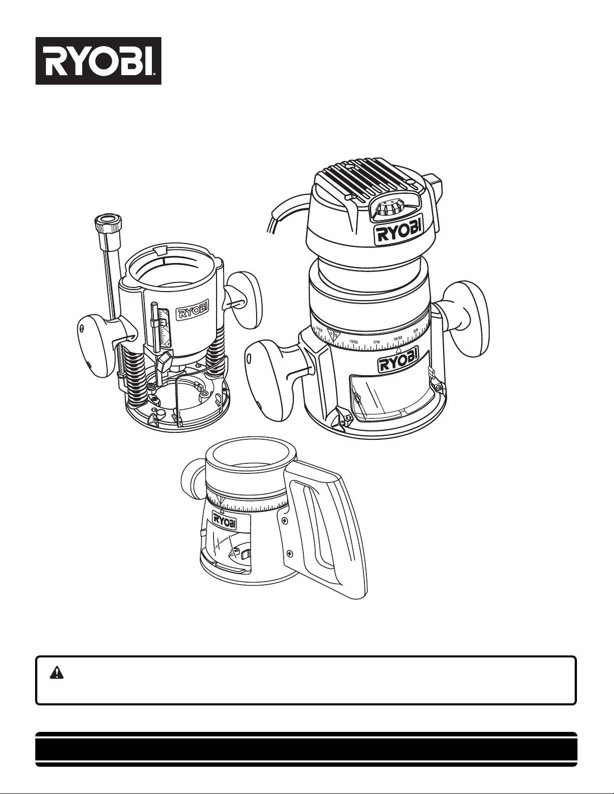
OPERATOR'S MANUAL
RE1802M1 ROUTER
With R181FB1 Fixed Base, R181PB1 Plunge
Base, and R181DB1 D-Handle Base
Double Insulated
1
/
3
2
1
0
2
15/32
7/16
3/
2
3
/
3
1
Your new router has been engineered and manufactured to our Ryobi’s high standard for dependability, ease of
operation, and operator safety. When properly cared for, the router will give you years of rugged, trouble-free
performance.
WARNING:
To reduce the risk of injury, the user must read and understand the operator’s manual before using this product.
Thank you for buying a Ryobi product.
SAVE THIS MANUAL FOR FUTURE REFERENCE

TABLE OF CONTENTS
■■
■ Introduction .................................................................................................................................................................... 2
■■
■■
■ General Safety Rules .................................................................................................................................................. 3-4
■■
■■
■ Specific Safety Rules ..................................................................................................................................................... 4
■■
■■
■ Symbols ...................................................................................................................................................................... 5-6
■■
■■
■ Electrical ........................................................................................................................................................................ 7
■■
■■
■ Features ...................................................................................................................................................................... 8-9
■■
■■
■ Unpacking ...................................................................................................................................................................... 9
■■
■■
■ Operation ................................................................................................................................................................. 10-22
■■
■■
■ Maintenance ................................................................................................................................................................. 23
■■
■■
■ Accessories ................................................................................................................................................................. 23
■■
■■
■ Parts, Ordering, and Service ......................................................................................................................................... 24
■■
INTRODUCTION
This router has many features for making its use more pleasant and enjoyable. Safety, performance, and dependability
have been given top priority in the design of this tool making it easy to maintain and operate.
2

GENERAL SAFETY RULES
WARNING:
Read and understand all instructions. Failure to follow
all instructions listed below, may result in electric shock,
fire and/or serious personal injury.
SAVE THESE INSTRUCTIONS
WORK AREA
■■
■ Keep your work area clean and well lit. Cluttered
■■
benches and dark areas invite accidents.
■■
■ Do not operate power tools in explosive atmo-
■■
spheres, such as in the presence of flammable
liquids, gases, or dust. Power tools create sparks
which may ignite the dust or fumes.
■■
■ Keep bystanders, children, and visitors away while
■■
operating a power tool. Distractions can cause you to
lose control.
■■
■ Avoid accidental starting. Be sure switch is off before
■■
plugging in. Carrying tools with your finger on the switch or
plugging in tools that have the switch on, invites accidents.
■■
■ Remove adjusting keys or wrenches before turning
■■
the tool on. A wrench or a key that is left attached to a
rotating part of the tool may result in personal injury.
■■
■ Do not overreach. Keep proper footing and balance
■■
at all times. Proper footing and balance enables better
control of the tool in unexpected situations.
■■
■ Use safety equipment. Always wear eye protection.
■■
Dust mask, non-skid safety shoes, hard hat, or hearing
protection must be used for appropriate conditions.
■■
■ Do not wear loose clothing or jewelry. Contain long
■■
hair. Loose clothes, jewelry, or long hair can be drawn
into air vents.
■■
■ Do not use on a ladder or unstable support. Stable
■■
footing on a solid surface enables better control of the
tool in unexpected situations.
ELECTRICAL SAFETY
■■
■ Double insulated tools are equipped with a polarized
■■
plug (one blade is wider than the other). This plug
will fit in a polarized outlet only one way. If the plug
does not fit fully in the outlet, reverse the plug. If it
still does not fit, contact a qualified electrician to
install a polarized outlet. Do not change the plug in
any way. Double insulation eliminates the need for
the three-wire grounded power cord and grounded power
supply system.
■■
■ Avoid body contact with grounded surfaces such as
■■
pipes, radiators, ranges, and refrigerators. There is an
increased risk of electric shock if your body is grounded.
■■
■ Don’t expose power tools to rain or wet conditions.
■■
Water entering a power tool will increase the risk of electric
shock.
■■
■ Do not abuse the cord. Never use the cord to carry the
■■
tools or pull the plug from an outlet. Keep cord away
from heat, oil, sharp edges, or moving parts. Replace
damaged cords immediately. Damaged cords increase
the risk of electric shock.
■■
■ When operating a power tool outside, use an outdoor
■■
extension cord marked “W-A” or “W”. These cords are
rated for outdoor use and reduce the risk of electric shock.
PERSONAL SAFETY
■■
■ Stay alert, watch what you are doing and use com-
■■
mon sense when operating a power tool. Do not use
tool while tired or under the influence of drugs,
alcohol, or medication. A moment of inattention while
operating power tools may result in serious personal
injury.
■■
■ Dress properly. Do not wear loose clothing or jew-
■■
elry. Contain long hair. Keep your hair, clothing, and
gloves away from moving parts. Loose clothes,
jewelry, or long hair can be caught in moving parts.
TOOL USE AND CARE
■■
■ Use clamps or other practical way to secure and
■■
support the workpiece to a stable platform. Holding
the work by hand or against your body is unstable and
may lead to loss of control.
■■
■ Do not force tool. Use the correct tool for your
■■
application. The correct tool will do the job better and
safer at the rate for which it is designed.
■■
■ Do not use tool if switch does not turn it on or off.
■■
Any tool that cannot be controlled with the switch is
dangerous and must be repaired.
■■
■ Disconnect the plug from power source before
■■
making any adjustments, changing accessories, or
storing the tool. Such preventive safety measures
reduce the risk of starting the tool accidentally.
■■
■ Store idle tools out of the reach of children and other
■■
untrained persons. Tools are dangerous in the hands of
untrained users.
■ Maintain tools with care. Keep cutting tools sharp
and clean. Properly maintained tools with sharp cutting
edges are less likely to bind and are easier to control.
■ Check for misalignment or binding of moving parts,
breakage of parts, and any other condition that may
affect the tool’s operation. If damaged, have the tool
serviced before using. Many accidents are caused by
poorly maintained tools.
■ Use only accessories that are recommended by the
manufacturer for your model. Accessories that may be
suitable for one tool, may become hazardous when used
on another tool.
■ Keep the tool and its handle dry, clean and free from
oil and grease. Always use a clean cloth when cleaning.
Never use brake fluids, gasoline, petroleum-based
products, or any strong solvents to clean your tool.
Following this rule will reduce the risk of loss of control
and deterioration of the enclosure plastic.
3

GENERAL SAFETY RULES
SERVICE
■■
■ Tool service must be performed only by qualified
■■
repair personnel. Service or maintenance performed by
unqualified personnel could result in a risk of injury.
■ When servicing a tool, use only identical replacement parts. Follow instructions in the Maintenance
section of this manual. Use of unauthorized parts or
failure to follow Maintenance Instructions may create a
risk of electric shock or injury.
SPECIFIC SAFETY RULES
■■
■ Hold tool by insulated gripping surfaces when performing an operation where the cutting tools may contact
■■
hidden wiring or its own cord. Contact with a “live” wire will make exposed metal parts of the cutting tool “live” and
shock the operator.
■■
■ Make sure your extension cord is in good condition.
ADDITIONAL SAFETY RULES
■■
■ Know your power tool. Read operator’s manual
■■
carefully. Learn its applications and limitations, as
well as the specific potential hazards related to this
tool. Following this rule will reduce the risk of electric
shock, fire, or serious injury.
■■
■ Always wear safety glasses. Everyday eyeglasses
■■
have only impact-resistant lenses; they are NOT
safety glasses. Following this rule will reduce the risk of
serious personal injury.
■■
■ Protect your lungs. Wear a face or dust mask if the
■■
operation is dusty. Following this rule will reduce the
risk of serious personal injury.
■■
■ Protect your hearing. Wear hearing protection during
■■
extended periods of operation. Following this rule will
reduce the risk of serious personal injury.
■■
■ Inspect tool cords periodically and, if damaged, have
■■
repaired at your nearest authorized service center.
Constantly stay aware of cord location. Following this
rule will reduce the risk of electric shock or fire.
■■
■ Check damaged parts. Before further use of the tool,
■■
a guard or other part that is damaged should be
carefully checked to determine that it will operate
properly and perform its intended function. Check for
alignment of moving parts, binding of moving parts,
breakage of parts, mounting, and any other conditions that may affect its operation. A guard or other
part that is damaged should be properly repaired or
replaced by an authorized service center. Following
this rule will reduce the risk of shock, fire, or serious
injury.
■■
■ Do not abuse cord. Never carry the tool by the cord
■■
or yank it to disconnect it from the receptacle. Keep
cord away from heat, oil, and sharp edges. Following
this rule will reduce the risk of electric shock or fire.
■■
When using an extension cord, be sure to use one
heavy enough to carry the current your product will
draw. A wire gage size (A.W.G.) of at least 14 is
recommended for an extension cord 50 feet or less
in length. A cord exceeding 50 feet is not recommended. If in doubt, use the next heavier gage. The
smaller the gage number, the heavier the cord. An
undersized cord will cause a drop in line voltage resulting in loss of power and overheating.
■■
■ Inspect for and remove all nails from lumber before
■■
routing. Following this rule will reduce the risk of
serious personal injury.
■■
■ Drugs, alcohol, medication. Do not operate tool
■■
while under the influence of drugs, alcohol, or any
medication. Following this rule will reduce the risk of
electric shock, fire, or serious personal injury.
■■
■ Save these instructions. Refer to them frequently and
■■
use them to instruct others who may use this tool. If you
loan someone this tool, loan them these instructions
also.
WARNING:
Some dust created by power sanding, sawing, grinding,
drilling, and other construction activities contains chemicals known to cause cancer, birth defects or other reproductive harm. Some examples of these chemicals are:
• lead from lead-based paints,
• crystalline silica from bricks and cement and
other masonry products, and
• arsenic and chromium from chemically-treated
lumber.
Your risk from these exposures varies, depending on how
often you do this type of work. To reduce your exposure
to these chemicals: work in a well ventilated area, and
work with approved safety equipment, such as those dust
masks that are specially designed to filter out microscopic particles.
4

SYMBOLS
Some of the following symbols may be used on this tool. Please study them and learn their meaning. Proper interpretation of
these symbols will allow you to operate the tool better and safer.
SYMBOL NAME DESIGNATION/EXPLANATION
V Volts Voltage
A Amperes Current
Hz Hertz Frequency (cycles per second)
W Watt Power
min Minutes Time
Alternating Current Type of current
---
n
o
.../min Per Minute Revolutions, strokes, surface speed, orbits etc., per minute
Direct Current Type or a characteristic of current
No Load Speed Rotational speed, at no load
Class II Construction Double-insulated construction
Wet Conditions Alert Do not expose to rain or use in damp locations.
Read The Operator’s Manual
Eye Protection
Safety Alert Precautions that involve your safety.
No Hands Symbol
To reduce the risk of injury, the user must read and understand
the operator’s manual before using this product.
Always wear safety goggles or safety glasses with side shields
and a full face shield when operating this product.
Failure to keep your hands away from the blade will result in
serious personal injury.
No Hands Symbol
No Hands Symbol
No Hands Symbol
Failure to keep your hands away from the blade will result in
serious personal injury.
Failure to keep your hands away from the blade will result in
serious personal injury.
Failure to keep your hands away from the blade will result in
serious personal injury.
5
SYMBOLS
The following signal words and meanings are intended to explain the levels of risk associated with this
product.
SYMBOL MEANING
DANGER: Indicates an imminently hazardous situation, which, if not avoided, will result in
death or serious injury.
WARNING: Indicates a potentially hazardous situation, which, if not avoided, could result in
death or serious injury.
CAUTION: Indicates a potentially hazardous situation, which, if not avoided, may result in
minor or moderate injury.
(Without Safety Alert Symbol) Indicates a situation that may result in property
damage.
SERVICE
Servicing requires extreme care and knowledge and should be
performed only by a qualified service technician. For service
we suggest you return the product to your nearest
AUTHORIZED SERVICE CENTER for repair. When servicing,
use only identical replacement parts.
WARNING:
WARNING:
To avoid serious personal injury, do not attempt to use
this product until you read thoroughly and understand
completely the operator's manual. Save this operator's
manual and review frequently for continuing safe operation and instructing others who may use this product.
Observe all normal safety precautgions related to avoiding electrical shock.
WARNING:
The operation of any tool can result in foreign objects being thrown into your eyes, which can result in severe
eye damage. Before beginning operation, always wear safety goggles or safety glasses with side shields and a
full face shield when needed. We recommend Wide Vision Safety Mask for use over eyeglasses or standard
safety glasses with side shields. Always wear eye protection which is marked to comply with ANSI Z87.1.
SAVE THESE INSTRUCTIONS
6
ELECTRICAL
DOUBLE INSULATION
Double insulation is a concept in safety in electric power
tools, which eliminates the need for the usual three-wire
grounded power cord. All exposed metal parts are
isolated from the internal metal motor components with
protecting insulation. Double insulated tools do not need
to be grounded.
Important: Servicing of a tool with double insulation
requires extreme care and knowledge of the system and
should be performed only by a qualified service
technician. For service, we suggest you return the tool to
your nearest authorized service center for repair. When
servicing, use only identical Ryobi replacement parts.
WARNING:
The double insulated system is intended to protect the
user from shock resulting from a break in the tool's
internal wiring. Observe all normal safety precautions
related to avoiding electrical shock.
ELECTRICAL CONNECTION
The router has a precision built electric motor. It should
be connected to a power supply that is 120 volts, 60 Hz,
AC only (normal household current). Do not operate this
tool on direct current (DC). A substantial voltage drop will
cause a loss of power and the motor will overheat. If your
tool does not operate when plugged into an outlet,
double-check the power supply.
EXTENSION CORDS
When using a power tool at a considerable distance from
a power source, be sure to use an extension cord that
has the capacity to handle the current the tool will draw.
An undersized cord will cause a drop in line voltage,
resulting in overheating and loss of power. Use the chart
to determine the minimum wire size required in an
extension cord. Only round jacketed cords listed by
Underwriter’s Laboratories (UL) should be used.
When working outdoors with a tool, use an extension cord
that is designed for outside use. This type of cord is
designated with “WA” on the cord’s jacket.
Before using any extension cord, inspect it for loose or
exposed wires and cut or worn insulation.
**Ampere rating (on tool faceplaate)
0-2.0 2.1-3.4 3.5-5.0 5.1-7.0 7.1-12.0 12.1-16.0
Cord Length Wire Size (A.W.G.)
25' 16 16 16 16 14 14
50' 16 16 16 14 14 12
100' 16 16 14 12 10 —
**Used on 12 gauge - 20 amp circuit.
WARNING:
Keep the extension cord clear of the working area. Position the cord so that it will not get caught on lumber, tools
or other obstructions while you are working with a power
tool. Failure to do so can result in serious personal injury.
WARNING:
Check extension cords before each use. If damaged replace immediately. Never use tool with a damaged cord
since touching the damaged area could cause electrical
shock resulting in serious injury.
7

FEATURES
SPECIFICATIONS
Depth of Cut:
Plunge Base ............................................................................................................................ 0 - 2 in. (0 - 51 mm)
Fixed Base & D-Base ........................................................................................................ 0 - 1-1/2 in. (0 - 38 mm)
Collet ........................................................................................................................................................ 1/2 in. (12.7 mm)
Collet Adaptor ............................................................................................................................................... 1/4 in. (6 mm)
Peak Horsepower ................................................................................................................................................................ 2
Ampere ................................................................................................................................................................... 10 Amps
Input ............................................................................................................................................ 120 Volts, 60 Hz, AC only
No Load Speed ....................................................................................................................................15,000 - 25,000 RPM
Power Cord ......................................................................................................................................................... 10 ft. (3 m)
Total Net Weight .......................................................................................................................................... 19 lbs. (8.6 kg.)
Before using this tool, familiarize yourself with all operating features and safety requirements. However, do not let
familiarity with the tool make you careless.
This new router is equipped with the following features.
See Figure 1.
MOTOR
The router kit has a powerful 10 amp motor with sufficient
power to handle tough routing jobs. It delivers 2 peak
horsepower for heavy duty performance.
SWITCH
The router has a conveniently located rocker switch.
SPINDLE LOCK
The spindle lock secures the spindle so that you only
need one wrench to loosen the collet nut and change
cutters.
DEPTH ADJUSTING RING
The depth adjusting ring allows you to adjust the depth of
cut.
VARIABLE SPEED
The router’s advanced electronic feature allow you to
adjust the motor speed to required job conditions. The
variable speed control is located on the front of the router
and allows the router to develop a no load speed from
15,000 to 25,000/min.
LOCKING ARM
The locking arm secures the motor housing in the base.
CHIP SHIELD
A plastic chip shield on the base of the router provides
protection against flying dust and chips.
ERGONOMIC DESIGN
The design of this tool provides for easy handling. It is
designed for comfort and ease of grasp when operating in
different positions and at different angles.
ELECTRICAL CONNECTION
Your router has a precision built electric motor. It should
be connected to a power supply that is 120 volts, 60
Hz, AC only (normal household current). Do not
operate this tool on direct current (DC). A substantial
voltage drop will cause a loss of power and overheating.
If your tool does not operate when plugged into an outlet,
double-check the power supply.
DOUBLE INSULATION
Double insulation is a concept in safety in electric power
tools, which eliminates the need for the usual three-wire
grounded power cord. All exposed metal parts are
isolated from the internal metal motor components with
protecting insulation. Double insulated tools do not need
to be grounded.
8
 Loading...