

Page 1
RuggedBackbone™RX1501
v2.4 Installation Guide
February 8, 2013
www.RuggedCom.com
Page 2

RuggedBackbone™ RX1501
Installation Guide
Copyright © 2013 RuggedCom Inc.
All rights reserved. Dissemination or reproduction of this document, or evaluation and communication of its contents, is not authorized
except where expressly permitted. Violations are liable for damages. All rights reserved, particularly for the purposes of patent application or
trademark registration.
This document contains proprietary information, which is protected by copyright. All rights are reserved. No part of this document may be
photocopied, reproduced or translated to another language without the prior written consent of RuggedCom Inc.
Disclaimer Of Liability
RuggedCom has verified the contents of this manual against the hardware and/or software described. However, deviations between the
product and the documentation may exist.
RuggedCom shall not be liable for any errors or omissions contained herein or for consequential damages in connection with the furnishing,
performance, or use of this material.
The information given in this document is reviewed regularly and any necessary corrections will be included in subsequent editions. We
appreciate any suggested improvements. We reserve the right to make technical improvements without notice.
Registered Trademarks
RuggedServer™, RuggedWireless™, RuggedCom Discovery Protocol (RCDP)™, RuggedExplorer™, Enhanced Rapid Spanning Tree
Protocol (eRSTP)™, ROX™, Rugged Operating System On Linux™, RuggedBackbone™, CrossBow™ and eLAN™ are trademarks of
RuggedCom Inc. Rugged Operating System (ROS)® and RuggedSwitch® are registered trademarks of RuggedCom Inc.
Other designations in this manual might be trademarks whose use by third parties for their own purposes would infringe the rights of the
owner.
Contacting RuggedCom
Corporate Headquarters US Headquarters Europe Headquarters
RuggedCom Inc.
300 Applewood Crescent
Concord, Ontario
Canada, L4K 5C7
Toll-free: 1 888 264 0006
Tel: +1 905 856 5288
Fax: +1 905 856 1995
E-mail: RuggedSales@RuggedCom.com
Web: www.RuggedCom.com
RuggedCom
1930 Harrison St., Suite 209
Hollywood, Florida
USA, 33020
Toll-free: 1 888 264 0006
Tel: +1 954 922 7938 ext. 103
Fax: +1 954 922 7984
RuggedCom
Unit 41, Aztec Centre,
Aztec West, Almondsbury, Bristol
United Kingdom, BS32 4TD
Tel: +44 1454 203 404
Fax: +44 1454 203 403
ii
Page 3

RuggedBackbone™ RX1501
Installation Guide
RuggedBackbone™RX1501
Table of Contents
FCC Statement And Cautions ............................................................................. v
Chapter 1
Product Overview ................................................................................................ 1
1.1 Functional Overview ..................................................................................................................... 1
1.2 Feature Highlights ........................................................................................................................ 1
Chapter 2
RuggedBackbone™ Modules .............................................................................. 5
2.1 Installing a Module ....................................................................................................................... 5
2.2 Front Panel .................................................................................................................................. 5
2.2.1 Module Status LEDs .......................................................................................................... 6
2.3 Line Modules (LM) ....................................................................................................................... 6
2.3.1 Ethernet - Copper ............................................................................................................. 7
2.3.2 Ethernet - Fiber ................................................................................................................. 7
2.3.3 SFP Modular ..................................................................................................................... 8
2.3.4 WAN ................................................................................................................................. 8
2.3.5 Serial ................................................................................................................................ 9
2.3.6 Cellular Modem ............................................................................................................... 10
2.3.7 DDS - Digital Data Services ............................................................................................. 10
2.3.8 RuggedAPE™ (Appplication Processing Engine) ............................................................... 10
2.4 Power Supply ............................................................................................................................ 10
Chapter 3
Installation .......................................................................................................... 13
3.1 Rack Mounting ........................................................................................................................... 13
3.1.1 Rack Mounting Dimensions .............................................................................................. 14
3.1.2 Panel and DIN Rail Mounting ........................................................................................... 15
3.1.3 Panel and DIN Rail Mounting Dimensions ......................................................................... 17
3.2 Power Supply Wiring and Grounding ........................................................................................... 17
3.2.1 Connectors for HI and HIP Power Modules ....................................................................... 18
3.2.2 Connectors for 24, 24P, 48, and 48P Power Modules ......................................................... 18
3.2.3 Chassis Ground Connection ............................................................................................. 19
3.2.4 AC Power Supply Wiring Example .................................................................................... 19
3.2.5 DC Power Supply Wiring Example ................................................................................... 20
iii
Page 4

RuggedBackbone™RX1501
3.3 Critical Alarm Wiring ................................................................................................................... 20
3.4 Serial Console Port .................................................................................................................... 21
3.5 WAN Ports: RJ45 ....................................................................................................................... 21
3.6 WAN Ports: BNC ........................................................................................................................ 22
3.7 Copper Ethernet Ports ................................................................................................................ 22
3.7.1 RJ45 Twisted-Pair Copper Ports ....................................................................................... 22
3.7.2 M12 Twisted Pair Copper Ports ........................................................................................ 23
3.7.3 Gigabit Ethernet 1000Base-TX Cabling Recommendations ................................................. 24
3.7.4 Transient Suppression ..................................................................................................... 25
3.8 Serial Ports: RJ45 ...................................................................................................................... 25
3.9 DDS Ports: RJ45 ....................................................................................................................... 26
3.10 DDS Rx and Tx LED Indications ............................................................................................... 26
3.11 SFP Optics – Installation, removal, and precautions .................................................................... 27
3.11.1 Module Insertion – SFP .................................................................................................. 27
3.11.2 SFP Module Removal .................................................................................................... 28
3.12 Fiber Ethernet Ports ................................................................................................................. 29
3.13 Cellular Modems ...................................................................................................................... 30
3.13.1 GSM, EDGE, HSPA+ Cellular Modem Card .................................................................... 31
3.13.2 Installing SIM Cards for GSM, EDGE, HSPA+ Cellular Modems ........................................ 32
RuggedBackbone™ RX1501
Installation Guide
Chapter 4
Technical Specifications ..................................................................................... 33
4.1 Power Supply Specifications ....................................................................................................... 33
4.2 Critical Alarm Relay Specifications .............................................................................................. 33
4.3 Copper Ethernet Port Specifications ............................................................................................ 34
4.4 Fiber Ethernet Port Specifications ............................................................................................... 34
4.4.1 Fast Ethernet (100Mbps) Optical Specifications ................................................................. 34
4.4.2 Gigabit Ethernet (1Gbps) Optical Specifications ................................................................. 35
4.5 Operating Environment ............................................................................................................... 36
4.6 RuggedAPE™ Specifications ...................................................................................................... 36
4.7 Mechanical Specifications ........................................................................................................... 37
Chapter 5
EMI And Environmental Type Tests .................................................................. 39
Chapter 6
Agency Approvals .............................................................................................. 43
Chapter 7
Warranty ............................................................................................................. 45
iv
Page 5
RuggedBackbone™ RX1501
Installation Guide
FCC Statement And Cautions
FCC Statement And Cautions
Federal Communications Commission Radio Frequency Interference Statement
This equipment has been tested and found to comply with the limits for a Class A digital device pursuant to Part
15 of the FCC Rules. These limits are designed to provide reasonable protection against harmful interference
when the equipment is operated in a commercial environment. This equipment generates, uses and can radiate
radio frequency energy and, if not installed and used in accordance with the instruction manual, may cause
harmful interference to radio communications. Operation of this equipment in a residential area is likely to cause
harmful interference in which case the user will be required to correct the interference at his own expense.
CAUTION!
This product contains a LASER system and is classified as a CLASS 1 LASER PRODUCT. Use of
controls or adjustments or performance of procedures other than those specified herein may result in
hazardous radiation exposure.
CAUTION!
This product contains no user-serviceable parts. Attempted service by unauthorized personnel shall
render all warranties null and void.
Changes or modifications not expressly approved by RuggedCom Inc. could invalidate specifications,
test results, and agency approvals, and void the user’s authority to operate the equipment.
Should this device require service, refer to Chapter 7, Warranty in this guide.
CAUTION!
This product should be installed in a restricted access location where access can only be gained by
service personnel or users who have been instructed about the reasons for the restrictions applied to
the location and about any precautions that shall be taken; and access is through the use of a tool or
lock and key, or other means of security, and is controlled by the authority responsible for the location.
v
Page 6

FCC Statement And Cautions
RuggedBackbone™ RX1501
Installation Guide
vi
Page 7

RuggedBackbone™ RX1501
Installation Guide
Product Overview
Product Overview
Section 1.1
Functional Overview
The RuggedBackbone™ RX1501 is a cost-efficient, rugged layer 3 switch and router. The RX1501’s modular
and field replaceable platform allows you to select WAN, serial, and Ethernet options, making it ideally suited for
electric power utilities, the industrial plant floor, and traffic control systems.
The RX1501 is designed to the RuggedRated™ specification, providing a high level of immunity to
electromagnetic interference (EMI) and heavy electrical surges typical of the harsh environments found in many
industrial applications. An operating temperature range of -40°C to +85°C (-40°F to +185°F) allows the RX1501 to
be placed in almost any location.
Chapter 1
Section 1.2
Feature Highlights
Cyber Security Features
• Multi-level passwords
• SSH/SSL encryption
• Enable/disable ports, MAC-based port security
• Port-based network access control (802.1x)
• VLAN (802.1Q) to segregate and secure network traffic
• RADIUS centralized password management
• SNMPv3 encrypted authentication and access security
RuggedRated™ for Reliability in Harsh Environments
• Immunity to EMI and high voltage electrical transients:
○ Zero-Packet-Loss Technology
○ Meets IEEE 1613 (electric utility substations)
○ Exceeds IEC 61850-3 (electric utility substations)
○ Exceeds IEC 61800-3 (variable speed drive systems)
○ Exceeds IEC 61000-6-2 (generic industrial environment)
• -40°C to +85°C operating temperature (no fans)
• Optional conformal coated printed circuit boards
• Failsafe Output Relay: For critical failure or error alarming
Functional Overview 1
Page 8

Chapter 1
Product Overview
Physical Ports
• Field replaceable line modules
• Up to 36 ports 100FX
• Up to 36 ports 10/100TX
• Up to 8 ports Gigabit Ethernet
WAN Port Options
• Up to 4 T1/E1 ports via RJ45 connectors (channelized/unchannelized)
• Up to 2 E1 ports via BNC connectors (channelized/unchannelized)
• Cellular/DDS
Serial Ports
• Fully compliant EIA/TIA RS485, RS422, RS232 serial ports (software selectable) with RJ45 connectors
• Raw socket mode support allows conversion of any serial protocol
Protocols
WAN
•
○ Frame Relay RFC 1490 or RFC 1294
RuggedBackbone™ RX1501
Installation Guide
○ PPP RFC 1661, 1332, 1321, 1334, PAP, CHAP Authentication
○ Multilink PPP RFC 1990
○ GOOSE messaging support
IP
•
○ Routing: OSPF, BGP, RIPv1, RIPv2
○ VRRP Agent
○ Traffic control, NTP Server, IP Multicast Routing
○ DHCP Agent (Option 82 Capable)
Frame Relay Support
• ISO and ITU compliant, network certified.
• ANSI T1.617 Annex D, Q.933 or LMI Local Signaling
Management Tools
• Web-based, SSH, CLI management interfaces
• SNMP v1, v2, and v3
• Remote Syslog
• Rich set of diagnostics with logging and alarms
• Loopback diagnostic tests
• Raw and interpreted real-time line traces
Universal Power Supply Options
• Single, removable power supply module
• Single power supply
• Fully integrated power supply (no external adaptor)
2 Feature Highlights
Page 9

RuggedBackbone™ RX1501
Installation Guide
• Input voltage ranges: 10-36VDC, 36-72VDC, 88-300VDC, 85-264VAC
• TUV/UL 60950 safety approved to 85°C
Warranty
• 5 Year Warranty
Product Overview
Chapter 1
Feature Highlights 3
Page 10

Chapter 1
Product Overview
RuggedBackbone™ RX1501
Installation Guide
4 Feature Highlights
Page 11
RuggedBackbone™ RX1501
Installation Guide
RuggedBackbone™ Modules
RuggedBackbone™ Modules
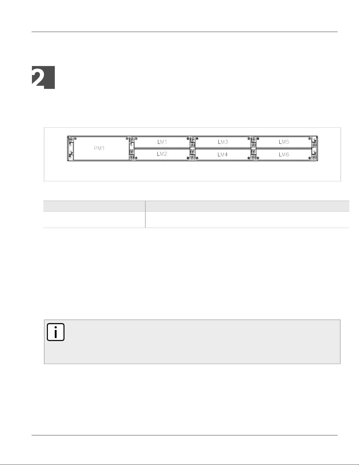
The RX1501 chassis provides seven module slots. Each slot accommodates a particular type of RuggedCom
module. Figure 1, “Chassis Slot Assignment” shows the module slots on the RX1501.
Figure 1: Chassis Slot Assignment
The RX1501 chassis supports the following modules:
Chapter 2
Parameter Description
LM1 through LM6 The RX1501 chassis supports up to six line module (LM) cards. For more information on line
All modules are built to the RuggedRated™ specifications of the RuggedBackbone™ RX1501. Each module type
is described in the following sections.
Section 2.1
modules, see Section 2.3, “Line Modules (LM)”.
Installing a Module
To install a module into the RuggedBackbone™ chassis, align the module guide ribs with the channels on
the chassis. Push the module in as far as it will go, being sure to push through the resistance provided by the
grounding springs. When properly seated, the module flange will rest on the main chassis frame. Tighten the
thumbscrews using finger strength only.
NOTE
Serial line modules are hot-swappable, meaning they can be removed and installed while the device is
running.
When installing a serial line module while the device is running, make sure internal VLANs are
enabled. For more information about configuring VLANs, refer to the ROX User Guide for the RX1501.
Section 2.2
Front Panel
The RX1501 Front Panel is equipped with an RS232 serial console port for initial management functions, and a
locally connected 10/100Base-T Ethernet port for system management out of band from the switch fabric.
Installing a Module 5
Page 12
Chapter 2
RuggedBackbone™ Modules
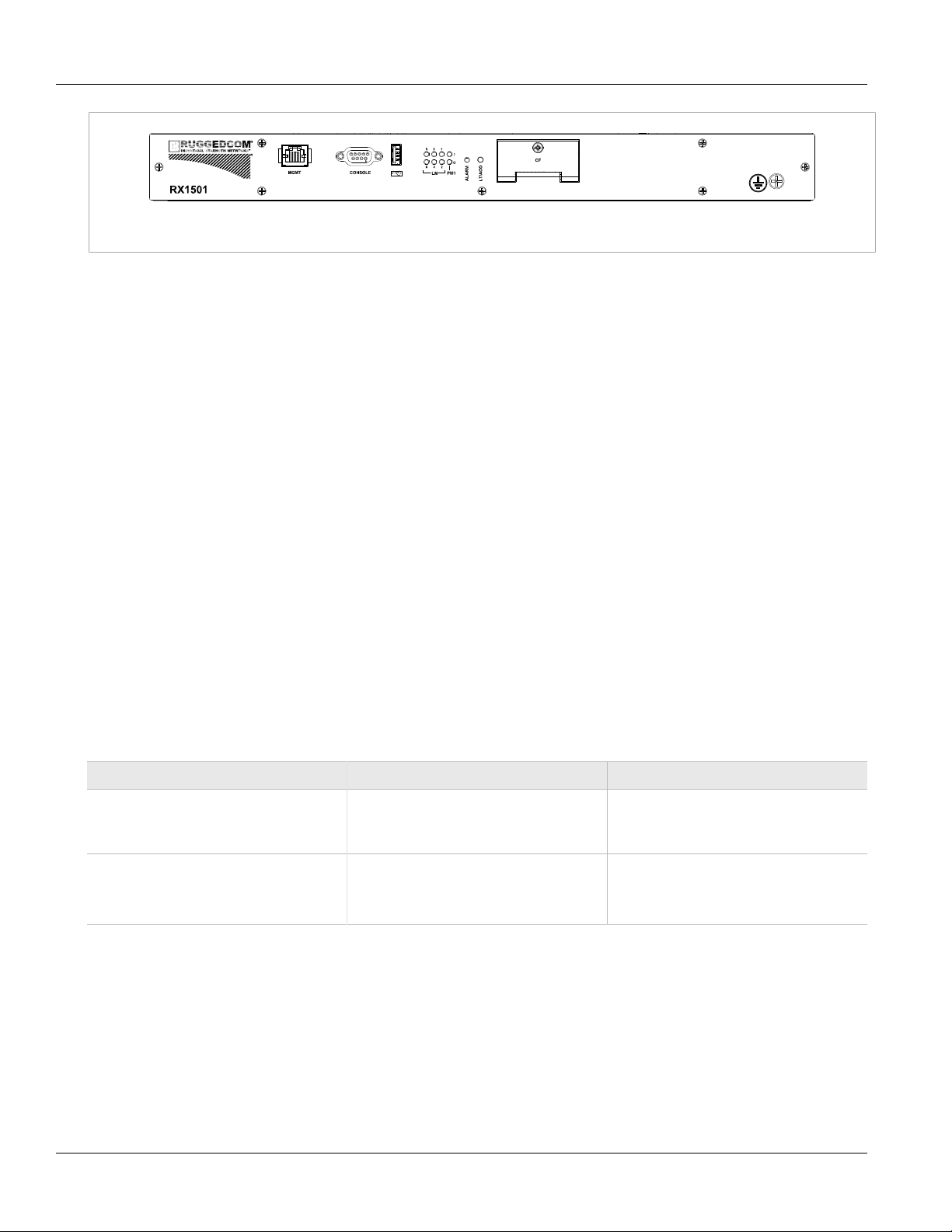
Figure 2: Front View
Other Front Panel features include:
• Utility USB port
• Power module indicator LED
• Line module indicator LEDs
• Alarm Indicator LED, which indicates system alarm status.
• Lamp Test / Alarm Cutoff (LT/ACO) button
• Removable 1GB Compact Flash (CF) card, which contains active and fallback installations of the ROX
operating system, along with the configuration database and other system data
• Chassis ground connection
For more information on connecting to the ports on the front panel, see the following topics:
• Serial Console: Section 3.4, “Serial Console Port”
• Management Ethernet Interface: Section 3.7, “Copper Ethernet Ports”
• Critical Alarm (Failsafe) Relay Interface: Section 3.3, “Critical Alarm Wiring”
RuggedBackbone™ RX1501
Installation Guide
Section 2.2.1
Module Status LEDs
The front panel module status LEDs provide the following information:
Table 1: Module Status LED Indications
LED Purpose Description
PM1 Indicates power supply status. I = Power supply is receiving input voltage.
O = Power supply is providing
output voltage to the RX1501.
LM 1 through 6 Indicates the line module status. Green = OK
Orange = Warning alert
Red = Configuration error
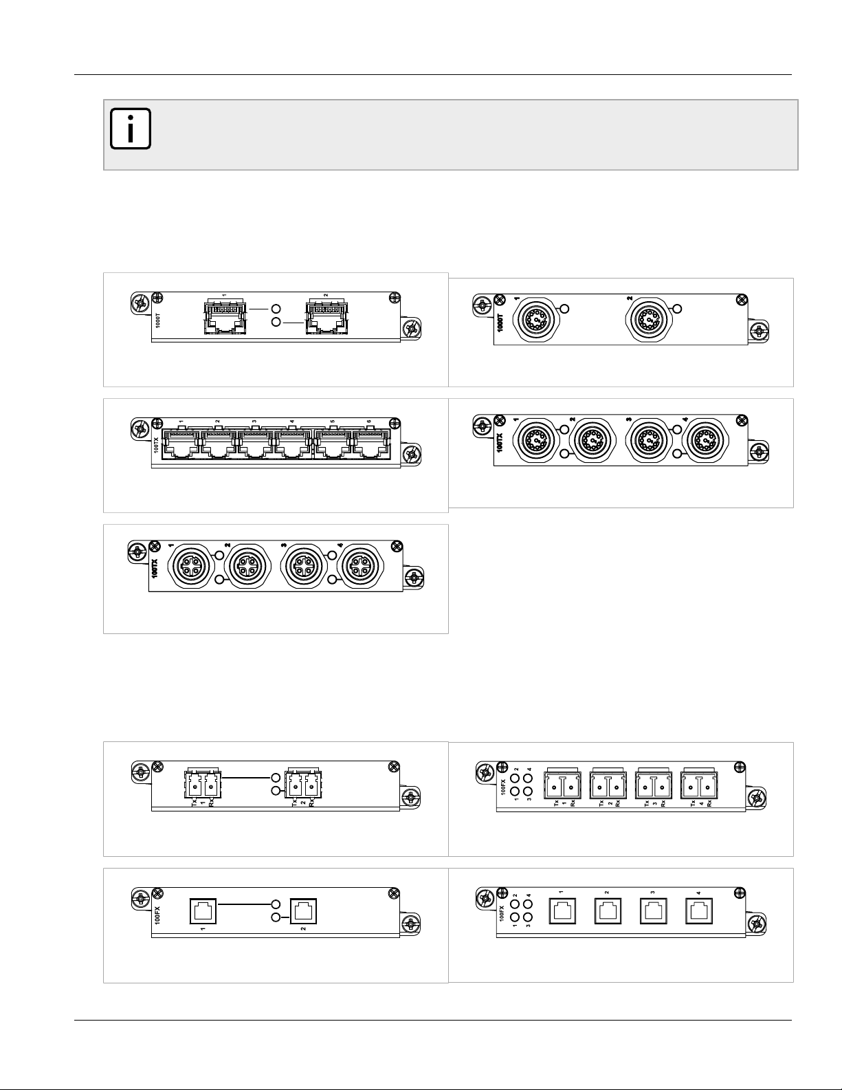
Section 2.3
Line Modules (LM)
The RuggedBackbone™ RX1501 supports six line modules in slots LM1 through LM6. Several types of line
modules may be ordered, depending on the type, speed and number of Ethernet ports required.
The following illustrations show the typical port configurations and connectors available for RX1501 line modules.
For complete information on the available line modules, refer to the RuggedBackbone™ RX1501 data sheet.
6 Module Status LEDs
Page 13
RuggedBackbone™ RX1501
Installation Guide
RuggedBackbone™ Modules
NOTE
Only one T1/E1 module may be used per router.
On the RX1501, 2-port modules can only be inserted in LM1 and LM2.
Section 2.3.1
Ethernet - Copper
Figure 3: CG01: 2 × 10/100/1000TX RJ45 Figure 4: CG03: 2 x 8-Pin 10/100/1000TX M12
Chapter 2
Figure 5: 6TX01: 6 × 10/100TX RJ45
Figure 7: 4TX04: 4 x 4-Pin 10/100TX M12
Section 2.3.2
Figure 6: 4TX03: 4 x 8-Pin 10/100TX M12
Ethernet - Fiber
Figure 8: FX**/FG**: 2 × 100FX/1000SX/1000LX LC Figure 9: 4FX**: 4 × 100FC LC
Figure 10: FX03: 2 × 100 FX MTRJ
Ethernet - Copper 7
Figure 11: 4FX03: 4 × 100FX MTRJ
Page 14
Chapter 2
RuggedBackbone™ Modules
RuggedBackbone™ RX1501
Installation Guide
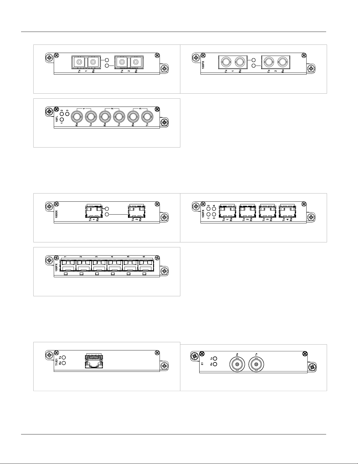
Figure 12: FX**: 2 × 100FX SC
Figure 14: FL01: 3 × 10FL/100SX
Section 2.3.3
Figure 13: FX**: 2 × 100FX ST
SFP Modular
Figure 15: FG5*: 2 × 1000LX/1000SX SFP Figure 16: FX5*: 4 × 100FX/100LX/100SX SFP
Figure 17: 6FX50: 6 × 100FX SFP
Section 2.3.4
WAN
Figure 18: TC1: 1 × T1/E1 RJ45 Figure 19: E01: 1 × E1 BNC
8 SFP Modular
Page 15
RuggedBackbone™ RX1501
Installation Guide
RuggedBackbone™ Modules
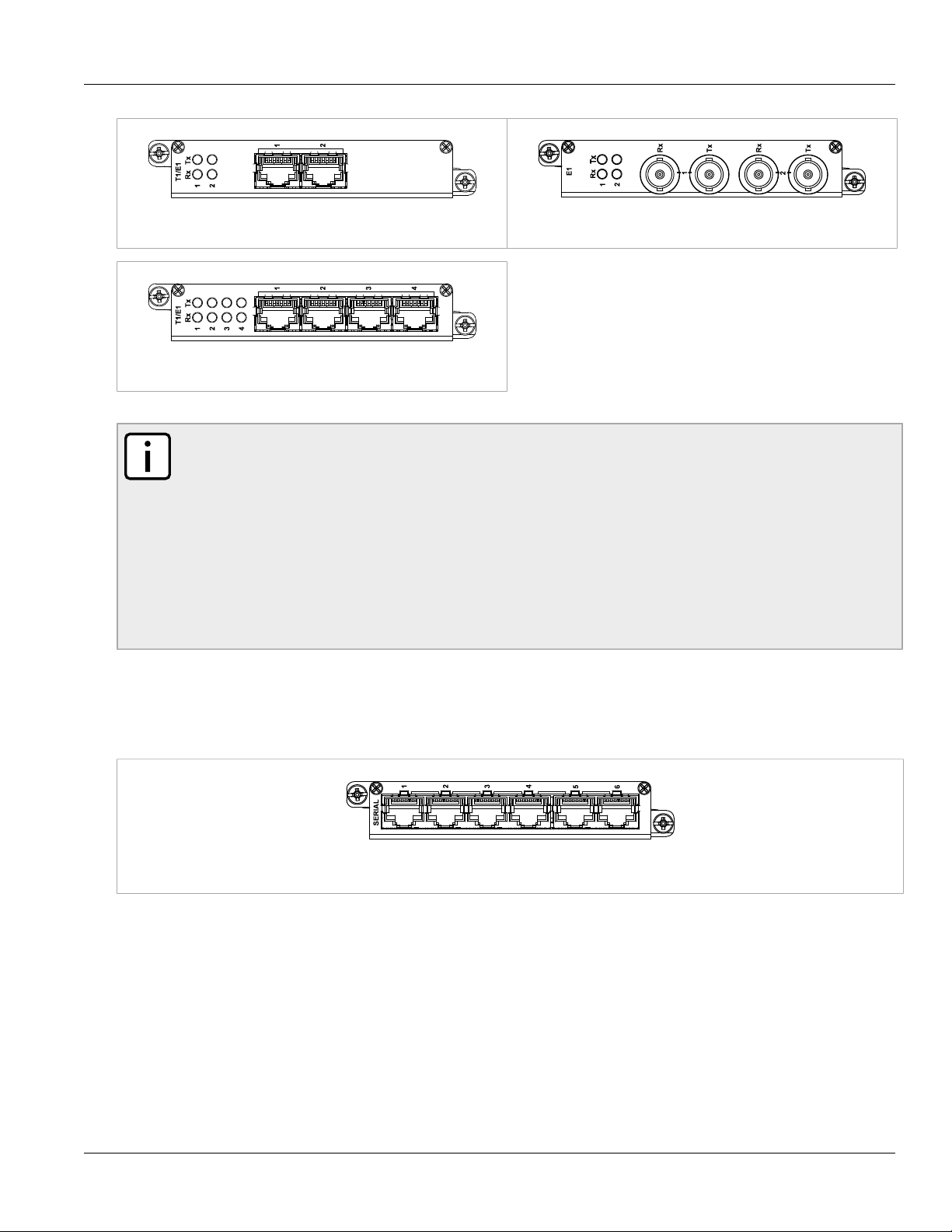
Chapter 2
Figure 20: TC2: 2 × T1/E1 RJ45
Figure 22: TC4: 4 × T1/E1 RJ45
NOTE
The TC1, TC2 and TC4 WAN modules comply with Part 68 of the FCC rules and requirements
adopted by ACTA. The product identifier is provided on a label on top of the modules. If requested, this
information must be provided to the telephone company.
The TC1, TC2 and TC4 WAN modules meet the Industry Canada's CS-03 Part II, Issue 9 technical
specifications. The industry Canada registration number and model number is provided on a label on
top of the modules.
The WAN modules TC1, TC2 and TC4 use only RJ48C connectors.
The modules have no user serviceable parts and equipment must only be repaired by authorized
RuggedCom personnel only.
Figure 21: E02: 2 × E1 BNC
Section 2.3.5
Serial
Figure 23: S01: 6 × Serial RJ45
Serial 9
Page 16
Chapter 2
RuggedBackbone™ Modules
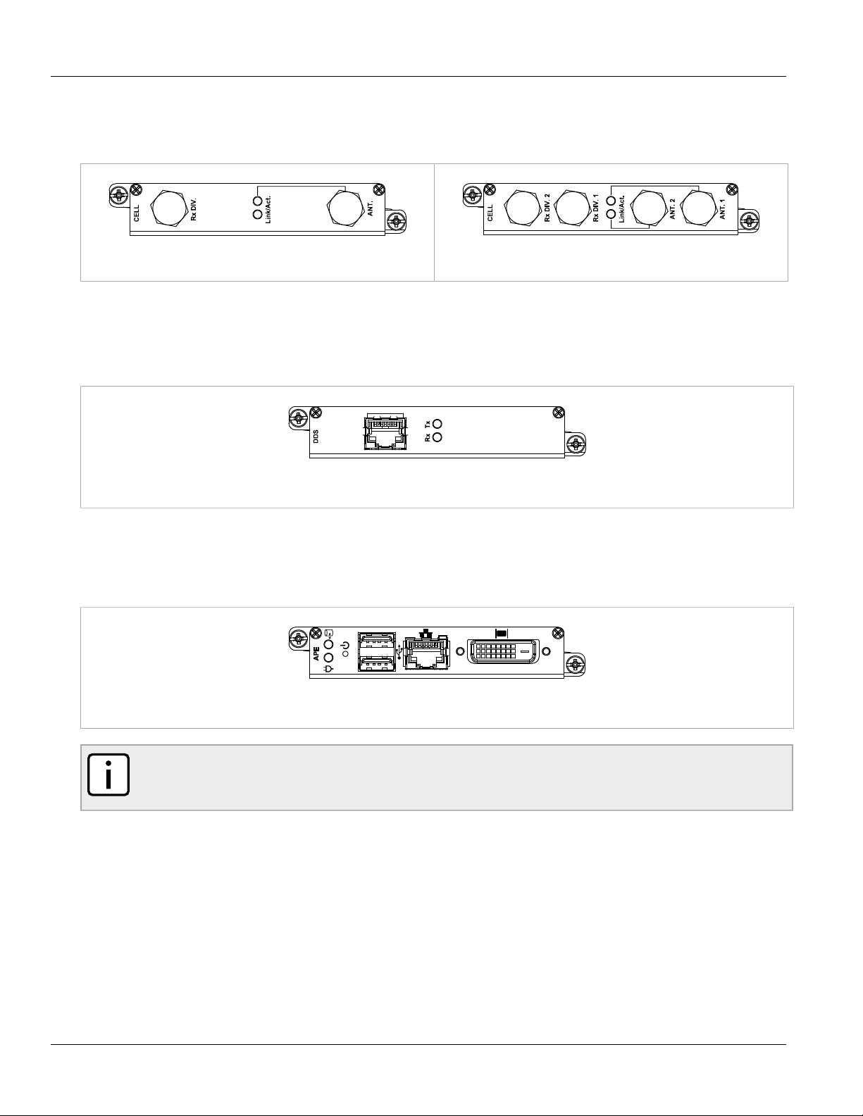
Section 2.3.6
Cellular Modem
Figure 24: W11, W21 Cellular Modem Figure 25: W12, W22, W32 Cellular Modem
Section 2.3.7
DDS - Digital Data Services
RuggedBackbone™ RX1501
Installation Guide
Figure 26: D02: 1 × DDS RJ45
Section 2.3.8
RuggedAPE™ (Appplication Processing Engine)
Figure 27: RuggedAPE™ Module
NOTE
For more information about the RuggedAPE module, including installation and setup instructions, refer
to the APE Installation and User Guide.
Section 2.4
Power Supply
The RX1501 is equipped with a single power module.
A single power module is capable of delivering a maximum of 42W, and accepts either AC or DC power at its
input.
10 Cellular Modem
Page 17

RuggedBackbone™ RX1501
PM
I
O
PM
I
O
Installation Guide
RuggedBackbone™ Modules
Power modules may be ordered with a screw terminal block or with a pluggable terminal block. The screw
terminal block features a safety cover which must be removed to make wiring connections, and must be replaced
after wiring is complete.
Power modules may be ordered as separate components. Refer to the RX1501 data sheet for complete ordering
details.
Figure 28: Screw terminal block power module: terminal cover in place (HI module shown)
Chapter 2
Figure 29: Screw terminal block power module: terminal cover removed (HI module shown)
Figure 30: Pluggable terminal block power module (HIP module shown)
Power Supply 11
Page 18

Chapter 2
RuggedBackbone™ Modules
RuggedBackbone™ RX1501
Installation Guide
12 Power Supply
Page 19

RuggedBackbone™ RX1501
REAR MOUNTING BRACKET
FRONT MOUNTING BRACKET
Installation Guide
Installation
Section 3.1
Rack Mounting
The RuggedBackbone™ RX1501 mounts to a standard 19" rack. Rack mounting brackets can be installed at the
front or rear of the chassis. Placing the connectors at the rear allows all data and power cabling to be installed
and connected on the same side of the rack.
Remove the black pan head Phillips screws from the front or rear mounting locations. Position the rack mounting
bracket, aligning the holes in the bracket with the screw holes on the chassis. Attach the mounting bracket with
the screws from the chassis. Torque all screws to 10 in-lbs.
For high-vibration or seismically active locations, use rack mounting brackets at all four corners of the chassis.
Chapter 3
Installation
NOTE
Due to the heat dissipated in the RX1501 chassis, it is recommended that 1 unit of rack space (1U
or 1.75") be left unpopulated and free of equipment above each RX1501 unit to allow for convection
airflow. Although forced airflow is not necessary, any increase in airflow will result in a reduction of
ambient temperature and will improve long-term reliability of all equipment mounted in the rack.
Figure 31: Side View of Mounting Brackets
Rack Mounting 13
Page 20

Chapter 3
Installation
Section 3.1.1
Rack Mounting Dimensions
Figure 32: RX1501Rack Mounting Dimensions – Front View
RuggedBackbone™ RX1501
Installation Guide
Figure 33: RX1501Rack Mounting Dimensions – Top View
14 Rack Mounting Dimensions
Page 21

RuggedBackbone™ RX1501
Installation Guide
Figure 34: RX1501Rack Mounting Dimensions – Rear View
Section 3.1.2
Panel and DIN Rail Mounting
The RuggedBackbone™ RX1501 features optional mounting brackets for panel and DIN rail mounting. The
optional brackets attach to both sides of the appliance at the rear of the chassis. For panel mounting, the
mounting bracket provides four mounting holes. For DIN rail mounting, the DIN adaptor mounts to a standard 1"
DIN rail and is secured with a lock screw on each adaptor.
To attach the mounting brackets, remove the black pan head Phillips screws from side of the appliance. Align the
brackets with the threaded holes on the sides of the appliance. Secure the mounting bracket with the screws from
the chassis. Torque all screws to 10 in-lbs.
Chapter 3
Installation
Figure 35: Installing Panel and DIN Rail Mounting Brackets
Panel and DIN Rail Mounting 15
Page 22

Chapter 3
Installation
Figure 36: DIN Rail Mounting
RuggedBackbone™ RX1501
Installation Guide
16 Panel and DIN Rail Mounting
Page 23

RuggedBackbone™ RX1501
Installation Guide
Section 3.1.3
Panel and DIN Rail Mounting Dimensions
Chapter 3
Installation
Figure 37: Panel and DIN Rail Mounting Dimensions
Section 3.2
Power Supply Wiring and Grounding
The RX1501 supports a single power supply, power module 1 (PM1). Power connections are located on the PM1
module face plate. An optional chassis ground connection is located on the front panel as shown in Figure 2,
“Front View”.
RX1501 products can be equipped with either a Phillips Screw Terminal Block or a Phoenix Plug Terminal
Block. The Phillips Screw Terminal Block has Phillips screws with compression plates, allowing either bare wire
connections or crimped terminal lugs. We recommend the use of #6 size ring lugs to ensure secure, reliable
Panel and DIN Rail Mounting Dimensions 17
Page 24

Chapter 3
Installation
RuggedBackbone™ RX1501
Installation Guide
connections under severe shock or vibration. Both terminal blocks have a safety cover, secured with two Phillips
screws, which must be removed to make connections. The safety cover must be re-attached after wiring to
ensure personnel safety.
For AC and DC power supply wiring examples, refer to Section 3.2.4, “AC Power Supply Wiring Example” and
Section 3.2.5, “DC Power Supply Wiring Example”.
WARNING!
The RX1501 has one (1) power supply installed. Service personnel must isolate all power supplies
prior to servicing.
Section 3.2.1
Connectors for HI and HIP Power Modules
Figure 38: Screw Terminal Power
Connector for HI Power Module
Section 3.2.2
Figure 39: Pluggable Phoenix Power
Connector for HIP Power Module
Connectors for 24, 24P, 48, and 48P Power Modules
Figure 40: Screw Terminal Power
Connector for 24 and 48 Power Modules
Figure 41: Pluggable Phoenix Power
Connector for 24P and 48P Power Modules
18 Connectors for HI and HIP Power Modules
Page 25

RuggedBackbone™ RX1501
Installation Guide
Section 3.2.3
Chassis Ground Connection
The RX1501 chassis ground connection, shown in Figure 42, “Chassis Ground Connection”, uses a #10-32
screw. It is recommended to terminate the ground connection in a #10 ring lug. Torque on the chassis ground
connection should not exceed 30 in-lbs (3.4 Nm).
Figure 42: Chassis Ground Connection
Chapter 3
Installation
Section 3.2.4
AC Power Supply Wiring Example
Figure 43: Wiring for Single AC Power Supply (HIP module shown)
NOTE
• For 125/230VAC rated equipment, a appropriately rated AC circuit breaker must be installed.
• It is recommended to provide a separate circuit breaker for each power supply module.
• Equipment must be installed according to applicable local wiring codes.
Chassis Ground Connection 19
Page 26

Chapter 3
+
Installation
Section 3.2.5
DC Power Supply Wiring Example
Figure 44: Wiring for Single DC Power Supply (24P or 48P module shown)
RuggedBackbone™ RX1501
Installation Guide
NOTE
• For 125/230VAC rated equipment, a appropriately rated AC circuit breaker must be installed.
• It is recommended to provide a separate circuit breaker for each power supply module.
• Equipment must be installed according to applicable local wiring codes.
Section 3.3
Critical Alarm Wiring
The Critical Alarm output relay signals critical error conditions that may occur on the RuggedBackbone™
RX1501. The contacts are energized upon power-up of the unit and remain energized unless a critical alarm
condition is detected. Relay connections are shown in the Critical Alarm Relay Connector diagram. You can
configure control of the relay output through the ROX user interface.
A common application for this output is to signal an alarm in case of a power failure.
20 DC Power Supply Wiring Example
Page 27

RuggedBackbone™ RX1501
Installation Guide
Figure 45: Critical Alarm Relay Connector
Section 3.4
Serial Console Port
Chapter 3
Installation
The serial console port on the front panel provides access to the boot-time control and configuration menu
interface, and a console interface to the ROX operating system.
The serial ports implement RS232 DCE on a female DB9 connector. Serial settings are: 57600 bps, 8 bits, No
parity, 1 stop bit. See the illustration and table below for pin configuration and assignment.
Table 2: DB9 Serial Console Pinout
DB9 Pin Signal Function
1 NC
2 TX
3 RX
4 NC
5 GND
6 NC
7 NC
8 NC
Figure 46: DB9 Serial Console Port
9 NC
Section 3.5
WAN Ports: RJ45
The RX1501 supports T1/E1 WAN ports, to interface to standard T1 or E1 telecommunication infrastructure.
Carefully note the orientation of the RJ45 receptacle when inserting or removing cabling. See the illustration and
table below for pin configuration and assignment.
Serial Console Port 21
Page 28

Chapter 3
Rx Tx
Chassis
RTIP
Chassis
TTIP
Installation
Figure 47: RJ45 T1/E1 Pin Configuration
Section 3.6
RuggedBackbone™ RX1501
Installation Guide
Table 3: RJ45 T1/E1 Pin Assignment
T1/E1 pinout
Pin Description
1 RRING
2 RTIP
3 NC
4 TRING
5 TTIP
6 NC
7 NC
8 NC
WAN Ports: BNC
The RX1501 supports optional E1 WAN ports with BNC connectors. The Tx and Rx connections are labelled on
the line module. See the illustration below for the connection configuration.
Figure 48: RJ45 T1/E1 Pin Configuration
Section 3.7
Copper Ethernet Ports
The RuggedBackbone™ RX1501 can be ordered with up to 36 10/100Base-TX ports that allow connection to
standard CAT-5 UTP cable with RJ45 male connectors. All copper Ethernet ports feature auto-negotiation, autopolarity, and auto-crossover functions. The female RJ45 connector can accept and take advantage of screened
(commonly known as “shielded”) cabling.
Section 3.7.1
RJ45 Twisted-Pair Copper Ports
Female RJ45 connectors are available on LMs that support 10/100Base-T and on LMs and SMs that support
10/100/1000Base-T Ethernet. See the illustration and table below for pin configuration and assignment.
22 WAN Ports: BNC
Page 29

RuggedBackbone™ RX1501
Installation Guide
Chapter 3
Installation
Table 4: RJ45 Ethernet Pin Assignment
RJ45 Pin 10/100Base-Tx 10/100/1000Base-Tx
1 RX+ A+
2 RX- A-
3 TX+ B+
4 NC C+
5 NC C-
Figure 49: RJ45 Ethernet Pin Configuration
6 TX- B-
7 NC D+
8 NC D-
Section 3.7.2
M12 Twisted Pair Copper Ports
M12 ports are available on LMs that support 10/100Base-TX and 10/100/1000Base-TX. See the illustrations and
tables below for pin configuration and assignmnt.
Table 5: 8-Pin A-coded M12 Ethernet Port Pin Assignment
Pin 10/100Base-Tx
Signal (On 4TX03)
1 NC (terminated
at GND)
2 NC (terminated
at GND)
3 NC (terminated
at GND)
10/100/1000Base-
Tx Signal (on CG03)
C+
D+
D-
4 TX- A-
Figure 50: 8-Pin A-coded M12
Ethernet Port Pin Configuration
5 RX+ B+
6 TX+ A+
7 NC (terminated
at GND)
8 RX- B-
C-
M12 Twisted Pair Copper Ports 23
Page 30

Chapter 3
Installation
Table 6: 4-Pin D-coded M12 Ethernet Port Pin Assignment
Pin 10/100Base-Tx Signal
1 TX+
2 RX+
3 TX-
4 RX-
Figure 51: 4-Pin D-coded M12
Ethernet Port Pin Configuration
Section 3.7.3
Gigabit Ethernet 1000Base-TX Cabling Recommendations
RuggedBackbone™ RX1501
Installation Guide
The IEEE 802.3ab Gigabit Ethernet standard defines 1000 Mbit/s Ethernet communications over distances of up
to 100 meters using 4 pairs of CAT-5 (or higher) balanced, unshielded twisted-pair cabling. For wiring guidelines,
system designers and integrators should refer to the Telecommunications Industry Association (TIA) TIA/EIA-568A wiring standard for minimum cabling performance specifications required for proper Gigabit Ethernet operation.
To ensure reliable, error-free data communications, new and pre-existing communication paths should be verified
for TIA/EIA-568-A compliance. The table: Cabling Categories and 1000Base-TX Compliance summarizes the
relevant cabling standards as they apply to 100Base-TX connections.
Table 7: Cabling Categories and 1000Base-TX Compliance
Cabling Category 1000Base-
TX Compliant
< 5 No New wiring infrastructure required.
5 Yes Verify TIA/EIA-568-A compliance.
5e Yes No action required. New installations should be designed with Category 5e or higher.
6 Yes No action required.
> 6 Yes Connector and wiring standards to be determined.
Required Action
Follow these recommendations for copper data cabling in high electrical noise environments:
• Data cable lengths should be as short as possible, ideally limited to 10' (3 m) in length. Copper data cables
should not be used for inter-building communications.
• Power and data cables should not be run in parallel for long distances, and should be installed in separate
conduits. Power and data cables should intersect at 90° angles when necessary to reduce inductive coupling.
• Optionally, shielded/screened cabling can be used. The cable shield should be grounded at one single point to
avoid the generation of ground loops.
24
Gigabit Ethernet 1000Base-TX Cabling
Recommendations
Page 31

RuggedBackbone™ RX1501
Installation Guide
Section 3.7.4
Transient Suppression
All copper Ethernet ports on RuggedCom products include transient suppression circuitry to protect against
damage from electrical transients and to ensure conformance to IEC 61850-3 and IEEE 1613 Class 1. This
means that during a transient electrical event, it is possible for communications errors or interruptions to occur,
but recovery is automatic.
NOTE
RuggedCom does not recommend the use of copper cabling of any length for critical, real-time,
substation automation applications.
RuggedCom also recommends against the use of copper Ethernet connections to interface to devices in the field
across distances which could produce high levels of ground potential rise (that is, greater than 2500V), during
line-to-ground fault conditions.
Section 3.8
Serial Ports: RJ45
Chapter 3
Installation
The RX1501 supports serial port line modules with RJ45 connections. On power-up, all serial ports default to
RS485 mode. Each port can be individually set to RS232, RS485, or RS422 mode via software.
Table 8: RJ45 RS232/RS485/RS422 Serial Pin Assignment
Pin RS232 Mode RS485 Mode RS422 Mode
1 — — RX-
2 Reserved
3 COM (Isolated GND)
4 COM (Isolated GND)
5 RX — RX+
6 TX TX/RX + TX +
Figure 52: RJ45 Serial Pin Configuration
7 CTS — —
8 RTS TX/RX - TX -
Shield Chassis GND
NOTE
Pin 2 is reserved for future IRIG-B output. Do not connect Pin 2 at this time; doing so may cause
hardware damage. Pins 7 and 8 are connected internally. No internal termination is provided. In RS232
mode, these pins enter a high impedance state. A DTE that asserts RTS will see CTS asserted, but
hardware flow control is not performed on the port.
Transient Suppression 25
Page 32

Chapter 3
Installation
Section 3.9
RuggedBackbone™ RX1501
Installation Guide
DDS Ports: RJ45
The RX1501 supports DDS port line modules with RJ45 connections. The 56 kbps DDS port is compatible with
Bellcore standards. Each DDS module features a single 56/64 kbps DDS line interface with a standard RJ45
receptacle.
Table 9: RJ45 DDS Pin Assignment
RJ45 Pin Description
1 R1: Transmit data to network (Ring 1)
2 T1: Transmit data to network (Tip 1)
3 NC
4 NC
5 NC
6 NC
Figure 53: RJ45 DDS Pin Configuration
Section 3.10
7 T: Receive data from network (Tip)
8 R: Receive data from network (Ring)
DDS Rx and Tx LED Indications
The DDS module features Rx and Tx LED indicators that display transmit and receive status.
Figure 54: DDS Module Rx and Tx LED Indicators
The following tables describe the DDS module Rx and Tx LED status indications:
Table 10: DDS Rx LED Indications
Rx LED Color Status
GREEN Frame sync detected and signal OK.
YELLOW Signal OK, but no frame sync.
RED Loss of signal.
OFF The interface is not enabled.
26 DDS Ports: RJ45
Page 33

RuggedBackbone™ RX1501
Installation Guide
Table 11: DDS Tx LED Indications
Tx LED Color Status
GREEN The interface is enabled and remote device has no errors.
YELLOW The interface is in loopback mode.
Chapter 3
Installation
RED Loss of signal or receiving any of OOS, UNM, or UMC codes: the remote device is out of service or has
OFF The interface is not enabled.
Section 3.11
problems with the signal.
SFP Optics – Installation, removal, and precautions
The RX1501 can be ordered with SFP (Small Form-factor Pluggable) pluggable optics modules. SFP modules
can be safely inserted and removed while the chassis is powered and operating. When inserting or removing
optics, observe the following precautions:
• Ensure that dust caps are mounted on SFP cages at all times, unless you are in the process of inserting or
removing an SFP module. The dust caps prevent the accumulation of residue or particles that might inhibit
proper operation.
• Ensure that you have properly discharged any possible electrostatic build-up to prevent electrostatic
discharges (ESD). This can be accomplished by proper grounding through an ESD wrist strap, or by touching
earth or chassis ground before installing or removing optical modules. ESD can damage or shorten the life of
optical modules when they are not plugged into a chassis.
• Ensure that SFP optical modules are always stored in an ESD-safe bag or other suitable ESD-safe
environment. Keep SFP modules free from moisture and store them at the proper temperature (-40°C to
+85°C).
• Disconnect all cables from the SFP module before inserting or removing the module.
• Use only components certified by RuggedCom Inc. with RuggedCom products. Damage can occur to optics
and product if compatibility and reliability have not been properly assessed.
Section 3.11.1
Module Insertion – SFP
Special attention must be paid to the orientation of SFP modules upon installation in the RX1501 chassis. The
figure below shows the proper orientation of SFP modules installed in both upper and lower line modules. SFP
modules on the upper row must be inserted top-side up. SFP modules on the lower row must be inserted top-side
down. SFP modules should be inserted with the bail-latch in the locked position.
SFP Optics – Installation, removal, and precautions 27
Page 34

Chapter 3
Installation
Figure 55: SFP module orientation
RuggedBackbone™ RX1501
Installation Guide
Figure 56: SFP module insertion
SFP modules should slide gently into their ports and should lock in place when fully inserted. Dust covers should
be in place when installing the modules, and should always be in place when cables are not connected.
Section 3.11.2
SFP Module Removal
To remove the SFP module, disconnect any cables and replace the dust cover to protect the optics. Extend the
bail latch found on the top of the module. Grasp the bail latch and gently pull outwards to unlock and remove the
module.
Immediately after removal, store the SFP module in an ESD-safe environment.
28 SFP Module Removal
Page 35

RuggedBackbone™ RX1501
Tx Rx
Installation Guide
Figure 57: SFP module removal
Chapter 3
Installation
Section 3.12
Fiber Ethernet Ports
Depending on the order code of the product, the RuggedBackbone™ RX1501 can be equipped with several
different types of fiber optic ports. The Transmit (TX) and Receive (RX) connections of each port must be properly
connected and matched for proper link establishment and operation. The drawings in the following figures show a
side and top view of each supported fiber optic connector type to assist in identifying the proper cable connection
orientation.
Table 12: Available Fiber Connector Types
Figure 58: LC
Figure 59: MTRJ
Fiber Ethernet Ports 29
Page 36

Chapter 3
Tx Rx
Tx Rx
Installation
RuggedBackbone™ RX1501
Installation Guide
Figure 60: SC
Figure 61: ST
Section 3.13
Cellular Modems
The RX1501 can be equipped with cellular modem modules for operation on GSM, EDGE, HSPA+, or CDMA
networks. The cellular modems feature 50 Ω SMA antenna connectors on the front plate of each module. The
following cellular modem modules are available:
Table 13: Cellular Modem Modules
Module Order Code Description
W11 1 Port Cell Modem GSM,EDGE,HSPA+
W12 2 Port Cell Modem GSM,EDGE,HSPA+
W21 1 Port Cell Modem EVDO Rev.A Verizon Wireless
W22 2 Port Cell Modem EVDO Rev.A Verizon Wireless
W32 1 Port Cell Modem GSM,EDGE,HSPA+, 1 Port Cell Modem EVDO Rev.A Verizon Wireless
Figure 62: Single Port Cellular Modem: Antenna Connections
30 Cellular Modems
Page 37

RuggedBackbone™ RX1501
Installation Guide
Figure 63: Dual Port Cellular Modem: Antenna Connections
NOTE
If two or more antennas are to be installed, the antennas must be separated by a minimum distance of
20 cm (7.9").
Chapter 3
Installation
Section 3.13.1
GSM, EDGE, HSPA+ Cellular Modem Card
The HSPA option is available for use on various GSM based networks. This option supports GSM, GPRS, EDGE,
UMTS and WCDMA/HSDPA/HSUPA. The Main antenna and Receive Diversity antenna connections are made to
the 50 Ω SMA connectors located on either side of the front faceplate.
Supported frequency bands are given in the following table. For safe operation of the device, ensure that the
maximum antenna gain is not exceeded.
Table 14: HSPA Antenna Requirements
Band
Band I
WCDMA 2100
Band II
WCDMA 1900
Band VIII
WCDMA 900
Band V
WCDMA 850
Band VI
WCDMA 800
Frequency Range
Tx (MHz) VSWR Rx (MHz) VSWR
1920-1980 <2.5:1 2110-2170 <3.5:1 Y 4
1850-1910 <2.5:1 1930-1990 <2.5:1 Y 4
880-915 <2.5:1 925-960 <3.5:1 Y 5
824-849 <2.5:1 869-894 <3.5:1 Y 5
830-840 <2.5:1 875-885 <3.5:1 Y 5
RX Diversity
Support
Maximum
Allowable
Gain (dBi)
GSM 850 824-849 <2.5:1 869-894 <3.5:1 — 5
EGSM 900 880-915 <2.5:1 925-960 <3.5:1 — 5
GSM 1800 1710-1785 <2.5:1 1805-1880 <3.5:1 — 4
GSM 1900 1850-1910 <2.5:1 1930-1990 <2.5:1 — 4
GSM, EDGE, HSPA+ Cellular Modem Card 31
Page 38

Chapter 3
Installation
Section 3.13.2
RuggedBackbone™ RX1501
Installation Guide
Installing SIM Cards for GSM, EDGE, HSPA+ Cellular Modems
NOTE
Be sure to take appropriate anti-static precautions before opening the cellular modem module.
1. Remove the module from the RX1501.
2. On the smooth side of the module, remove the four screws and remove the back of the module.
Figure 64: Cellular Modem Module Assembly:
W11 and W32 Single Antenna Modules
Figure 65: Cellular Modem Module
Assembly: W12 Dual Antenna Modules
3. Note the location of the SIM card cages. For modules W11 and W32, install the SIM card in SIM 1. For
module W22, install a SIM card in both SIM 1 and SIM 2.
4. Top open a SIM card cage, slide the silver catch down towards the antenna connector end of the module and
flip the cage open.
5. Hold the SIM card at its notched end, with its connectors facing down, and insert the SIM card into the cage.
6. Flip the cage down and slide the silver catch up away from the antenna connector end of the module.
7. Replace the back of the module and secure the back of the module with the four screws removed earlier.
8. Re-install the module in the RX1501.
32
Installing SIM Cards for GSM, EDGE, HSPA+ Cellular
Modems
Page 39

RuggedBackbone™ RX1501
Installation Guide
Technical Specifications
Section 4.1
Power Supply Specifications
Table 15: Power Supply Specifications
Technical Specifications
Chapter 4
Power
Supply Type
HI
HIP
24 10 VDC 36 VDC 2A(T)
24P 10 VDC 36 VDC 2A(T)
48 36 VDC 72 VDC 2A(T)
48P 36 VDC 72 VDC 2A(T)
a
Power consumption varies based on configuration.
b
(T) denotes time-delay fuse.
Min Max
88 VDC 300 VDC
85 VAC 264 VAC
88 VDC 300 VDC
85 VAC 264 VAC
Section 4.2
Input Range
Internal
Fuse Rating
b
2A(T)
b
2A(T)
b
b
b
b
Max. Power
Consumption
65W Max 50W
65W Max 50W
52W Max 42W
52W Max 42W
52W Max 42W
52W Max 42W
a
Max Power
Output
Connections
Screw
terminal block
Pluggable
terminal block
Screw
terminal block
Pluggable
terminal block
Screw
terminal block
Pluggable
terminal block
Critical Alarm Relay Specifications
Table 16: Form C Contact Relay Specifications
Voltage Current
30VDC 5A
250VAC 6.25A
Power Supply Specifications 33
Page 40

Chapter 4
Technical Specifications
RuggedBackbone™ RX1501
Installation Guide
Section 4.3
Copper Ethernet Port Specifications
The RX1501 can be ordered with several different modules which contain 10/100Tx or 10/100/1000Tx Ethernet
ports. All copper Ethernet ports have the following specifications:
Table 17: Copper Ethernet Port Specifications
Parameter Specification Notes
Speed 10/100 or 10/100/1000 Mbps Auto-negotiating
Duplex FDX / HDX Auto-negotiating
Cable-Type > Category 5 Shielded/Unshielded
Wiring Standard TIA/EIA T568A/B Auto-Crossover, Auto-Polarity
Max Distance 100 m
Connector RJ45
M12 8-Pin A-Coded
M12 4-Pin D-Coded
Isolation 1.5kV RMS 1-minute
Section 4.4
Fiber Ethernet Port Specifications
The following sections detail fiber optic specifications for ports that can be ordered with the modules on a
RuggedBackbone™ RX1501. The user determines the type of optics at time of ordering, and can determine the
modules installed on a particular unit by reading the factory data file via the ROX user interface. Section 4.4.1,
“Fast Ethernet (100Mbps) Optical Specifications” and Section 4.4.2, “Gigabit Ethernet (1Gbps) Optical
Specifications” list the specifications of the optical transceivers used in the fiber Ethernet modules available for
the RX1501. The specifications are organized by order code. Module order codes are contained within each
unit when it is assembled and configured at the factory. Consult the RuggedCom ROX User Guide for help in
obtaining the factory configuration data.
Section 4.4.1
Fast Ethernet (100Mbps) Optical Specifications
Fixed Fast Ethernet Transceivers
Table 18: Fast Ethernet (100Mbps) Optical Specifications
Order
Code
FX01 MM ST
FX02 MM SC
34 Copper Ethernet Port Specifications
Mode Connector
Type
Cable
Type
(μm)
62.5/125 -19 12
50/125
62.5/125 -19 12
50/125
Tx λ
(typ.)
(nm)
1300
1300
Tx min.
(dBm)
-22.5
-22.5
Tx max.
(dBm)RxSensitivity
(dBm)
-14 -31 -14 2
-14 -31 -14 2
Rx
Saturation
(dBm)
Distance
(typ.)
(km)
Power
Budget
(dB)
8.5
8.5
Page 41

RuggedBackbone™ RX1501
Installation Guide
Technical Specifications
Chapter 4
Order
Code
FX11 and
4FX11
FX03 and
4FX03
FX04 SM ST 9/125 1300 -15 -8 -32 -3 20 17
FX05 SM SC 9/125 1300 -15 -8 -31 -7 20 16
FX06 and
4FX06
FX07 SM SC 9/125 1300 -5 0 -34 -3 50 29
FX08 and
4FX08
FX09 SM SC 9/125 1300 0 5 -37 0 90 37
FX10 and
4FX10
Mode Connector
Type
MTRJ 62.5/125 -19 12
MM
LC 50/125
MM MTRJ
SM LC 9/125 1300 -15 -8 -34 -7 20 19
SM LC 9/125 1300 -5 0 -35 3 50 30
SM LC 9/125 1300 0 5 -37 0 90 37
Cable
Type
(μm)
62.5/125 -19 12
50/125
Tx λ
(typ.)
(nm)
1300
1300
Tx min.
(dBm)
-22.5
-22.5
Tx max.
(dBm)RxSensitivity
(dBm)
-14 -31 -14 2
-14 -31 -14 2
Rx
Saturation
(dBm)
Distance
(typ.)
(km)
SFP Fast Ethernet Transceivers
Power
Budget
(dB)
8.5
8.5
Table 19: SFP Fast Ethernet Transceivers
Order
Code
FX51 MM LC
FX52 SM LC 9/125 1300 -15 -8 -31 -8 20 16
FX53 SM LC 9/125 1300 -5 0 -34 0 50 29
FX54 SM LC 9/125 1550 -5 0 -34 -10 90 29
Mode Connector
Type
Cable
Type
(μm)
62.5/125 -20 11
50/125
Tx λ
(typ.)
(nm)
1310
Tx min
(dBm)
-23.5
Tx max
(dBm)RxSensitivity
(dBm)
-14 -31 -14 2
Section 4.4.2
Gigabit Ethernet (1Gbps) Optical Specifications
Fixed Gigabit Transceivers
Table 20: Fixed Gigabit Transceivers
Order
Code
Mode
Connector
Type
Cable
Type
(μm)
Tx λ
(typ.)
(nm)
Tx min
(dBm)
Tx max
(dBm)
Sensitivity
(dBm)
Rx
Rx
Saturation
(dBm)
Rx
Saturation
(dBm)
Distance
(typ.)
(km)
Distance
(typ.)
(km)
Power
Budget
(dB)
7.5
Power
Budget
(dB)
FG01 MM LC 50/125 850 -9 -2.5 -20 0 0.5 11
FG02 SM SC 9/125 1310 -10 -3 -20 -3 10 10
FG03 SM LC 9/125 1310 -9.5 -3 -21 -3 10 11.5
Gigabit Ethernet (1Gbps) Optical Specifications 35
Page 42

Chapter 4
Technical Specifications
RuggedBackbone™ RX1501
Installation Guide
Order
Code
FG04 SM SC 9/125 1310 -5 0 -20 -3 25 15
FG05 SM LC 9/125 1310 -7 -3 -24 -3 25 17
Mode
Connector
Type
Cable
Type
(μm)
Tx λ
(typ.)
(nm)
Tx min
(dBm)
Tx max
(dBm)
Rx
Sensitivity
(dBm)
Rx
Saturation
(dBm)
Distance
(typ.)
(km)
Power
Budget
(dB)
SFP Gigabit Transceivers
Table 21: SFP Gigabit Transceivers
Order
Code
FG51 MM LC
FG52 SM LC 9/125 1310 -9.5 -3 -19 -3 10 9.5
FG53 SM LC 9/125 1310 -7 -3 -23 -3 25 16
FG54 SM LC 9/125 1550 0 5 -23 -3 70 23
Notes:
1. Maximum segment length is greatly dependent on factors such as fiber quality, and the number of patches
and splices. Please consult RuggedCom sales associates when determining maximum segment distances.
2. All optical power numbers are listed as dBm averages.
3. F51 transceivers are rated for -40°C to +85°C.
Mode Connector
Type
Cable
Type
(μm)
50/125 0.5
62.5/125
Tx λ
(typ.)
(nm)
850 -9 -2.5 -20 0
Tx min
(dBm)
Tx max
(dBm)RxSensitivity
(dBm)
Saturation
(dBm)
Rx
Distance
(typ.)
(km)
0.3
Power
Budget
(dB)
11
Section 4.5
Operating Environment
Table 22: Operating Environment
Parameter Range Comments
Ambient Operating Temperature -40°C to 85°C Ambient Temperature as measured from a 30cm
radius surrounding the center of the enclosure.
Section 4.6
RuggedAPE™ Specifications
Table 23: RuggedAPE™ Specifications
Feature APE1402 APE1402W7 APE1404 APE1404W7 APE1404CPK
Processor Intel Atom E660 1.3 GHz, 512KB L2 Cache Intel Atom E660T 1.3 GHz, 512KB L2 Cache
RAM 2 GB DDR2, 800 MHz, 32-bit
Disk 8 GB SATA, solid state 16 GB SATA, solid state
Networking Realtek RTL8111, RJ45 Gigabit Ethernet interface
36 Operating Environment
Page 43

RuggedBackbone™ RX1501
Installation Guide
Feature APE1402 APE1402W7 APE1404 APE1404W7 APE1404CPK
USB 2 x USB 2.0, maximum combined USB device power consumption 500 mA at 5 V
Video Intel 4108 Grpahics Processor, DVI-D
LED Indications Power and Disk
Contols Momentary contact reset button
Temperature Range -40C to 70C
Power Requirements 12W with no USB load, 14.5W with full USB load
Technical Specifications
Chapter 4
Software Platform Debian Linux® Windows®
Embedded Standard
7
Section 4.7
Mechanical Specifications
Table 24: Mechanical Specifications
Parameter Value Comments
Dimensions 1.74 × 17.36 × 11.9 inches
44.20 × 440.94 × 302.26 mm
Weight Approximately 10.3 lbs (4.7 kg) Weight dependent on module selection.
Ingress Protection IP40
Enclosure Aluminum
Debian Linux® Windows®
Embedded Standard
7
(Height × Width × Depth)
Check Point GAiA™
OS
Mechanical Specifications 37
Page 44

Chapter 4
Technical Specifications
RuggedBackbone™ RX1501
Installation Guide
38 Mechanical Specifications
Page 45

RuggedBackbone™ RX1501
Installation Guide
EMI And Environmental Type Tests
Table 25: IEC 61850-3 EMI Type Tests
EMI And Environmental Type Tests
Chapter 5
Test Description Test Levels Severity
Enclosure Contact +/- 8 kV 4IEC 61000-4-2 ESD
Enclosure Air +/- 15 kV 4
IEC 61000-4-3 Radiated RFI Enclosure Ports 20 V/m Note
IEC 61000-4-4 Burst (Fast Transient)
IEC 61000-4-5 Surge
IEC 61000-4-6 Induced (Conducted) RFI
Signal ports +/- 4kV @ 2.5kHz Note
D.C. Power ports +/- 4kV 4
A.C. Power ports +/- 4kV 4
Earth ground ports +/- 4kV 4
Signal ports +/- 4kV line-to-earth,
+/- 2kV line-to-line
D.C. Power ports +/- 2kV line-to-earth,
+/- 1kV line-to-line
A.C. Power ports +/- 4kV line-to-earth,
+/- 2kV line-to-line
Signal ports 10V 3
D.C Power ports 10V 3
A.C. Power ports 10V 3
Levels
4
3
4
a
a
Earth ground ports 10V 3
IEC 61000-4-8 Magnetic Field Enclosure Ports
D.C. Power ports 30% for 0.1s, 60% for
A.C. Power ports 30% for 1 period, 60% for 50 periods N/A
IEC 61000-4-11 Voltage Dips & Interrupts A.C. Power ports 100% for 5 periods,
Signal ports 2.5kV common, 1kV
D.C. Power ports 2.5kV common, 1kV
40 A/m, continuous,
1000 A/m for 1 s
1000 A/m for 1 s 5
0.1s, 100% for 0.05s
100% for 50 periods
diff. mode@1MHz
diff. mode@1MHz
Note
N/AIEC 61000-4-29 Voltage Dips & Interrupts
N/A
3IEC 61000-4-12 Damped Oscillatory
3
a
39
Page 46

Chapter 5
EMI And Environmental Type Tests
RuggedBackbone™ RX1501
Installation Guide
Test Description Test Levels Severity
A.C. Power ports 2.5kV common, 1kV
D.C. Power ports 30V Continuous, 300V for 1s 4
IEC 61000-4-17 Ripple on D.C.
D.C. Power ports 10% 3
Power Supply
IEC 60255-5 Dielectric Strength
D.C. Power ports 1.5kVDC N/A
A.C. Power ports 2kVAC N/A
IEC 60255-5 H.V. Impulse
D.C. Power ports 5kV N/A
A.C. Power ports 5kV N/A
a
RuggedCom-specified severity levels
Table 26: IEEE 1613 (C37.90.x) EMI Immunity Type Tests
Test Description Test Levels
Levels
3
diff. mode@1MHz
Signal ports 30V Continuous, 300V for 1s 4IEC 61000-4-16 Mains Frequency Voltage
Signal ports 2kVAC (Fail-Safe Relay output) N/A
Signal ports 5kV (Fail-Safe Relay output) N/A
b
Enclosure Contact +/-2kV, +/-4kV, +/- 8kVIEEE C37.90.3 ESD
Enclosure Air +/-4kV, +/-8kV, +/-15kV
IEEE C37.90.2 Radiated RFI Enclosure ports 35 V/m
IEEE C37.90.1 Fast Transient
Signal ports +/- 4kV @ 2.5kHz
D.C. Power ports +/- 4kV
A.C. Power ports +/- 4kV
Earth ground ports +/- 4kV
IEEE C37.90.1 Oscillatory
Signal ports 2.5kV common mode @1MHz
D.C. Power ports 2.5kV common, 1kV diff. mode@1MHz
A.C. Power ports 2.5kV common, 1kV diff. mode@1MHz
IEEE C37.90 H.V. Impulse
Signal ports 5kV (Fail-Safe Relay output)
D.C. Power ports 5kV
A.C. Power ports 5kV
IEEE C37.90 Dielectric Strength
Signal ports 2kVAC
D.C. Power ports 1.5kVDC
A.C. Power ports 2kVAC
b
Meets Class 2 requirements for an all-fiber configuration. Meets Class 1 requirements for copper ports.
Table 27: Environmental Type Tests
Test Description Test Levels
IEC 60068-2-1 Cold Temperature Test Ad -40°C, 16 Hours
40
Page 47

RuggedBackbone™ RX1501
Installation Guide
Test Description Test Levels
IEC 60068-2-2 Dry Heat Test Bd +85°C, 16 Hours
IEC 60068-2-30 Humidity (Damp Heat, Cyclic) Test Db 95% (non-condensing), 55°C , 6 cycles
IEC 60255-21-1 Vibration 2g @ (10 - 150) Hz
IEC 60255-21-2 Shock 30g @ 11mS
EMI And Environmental Type Tests
Chapter 5
41
Page 48

Chapter 5
EMI And Environmental Type Tests
RuggedBackbone™ RX1501
Installation Guide
42
Page 49

RuggedBackbone™ RX1501
Installation Guide
Agency Approvals
Table 28: Agency Approvals
Agency Standards Comments
Agency Approvals
Chapter 6
TUV
CE EN 60950, EN 61000-6-2
FCC FCC Part 15, Class A
CISPR EN55022, Class A
FDA/CDRH 21 CFR Chapter 1, Subchapter J Laser Eye Safety
ISO ISO9001:2008
ACTA FCC Part 68 TC1, TC2 and TC4 line modules
Industry Canada IC CS-03 Part II, Issue 9 TC1, TC2 and TC4 line modules
GSM: 850/900/1800/1900, UMTS FDD:
Band I/Band II/Band V/Band VIII [http://
PTCRB
view_complete_request_guest.cfm?
Cellco Partnership d/b/a Verizon Wireless MA-00203-2009
UL 60950-1:2007,
CAN/CSA-C22.2 No. 60950-1-07
www.ptcrb.com/vendor/complete/
modelid=19987]
CE Compliance is claimed via
Declaration of Self Conformity Route
Designed and manufactured using an
ISO9001: 2008 certified quality program
Cellular LM Models RX1500PN-W11-XX
RX1500PN-W12-XX RX1500PN-W32-XX
Carrier Certification for Cellular
LM Models RX1500PN-W21-XX
RX1500PN-W22-XX RX1500PN-W32-XX
43
Page 50

Chapter 6
Agency Approvals
RuggedBackbone™ RX1501
Installation Guide
44
Page 51

RuggedBackbone™ RX1501
Installation Guide
Warranty
RuggedCom warrants this product for a period of five (5) years from the date of purchase. This product contains
no user-serviceable parts. Attempted service by unauthorized personnel shall render all warranties null and void.
For warranty details, visit www.RuggedCom.com or contact your customer service representative.
Should this product require service, contact the factory at:
RuggedCom Inc.
300 Applewood Crescent
Concord, Ontario
Canada L4K 5C7
Phone: +1 905 856 5288
Fax: +1 905 856 1995
Chapter 7
Warranty
45
Page 52

Chapter 7
Warranty
RuggedBackbone™ RX1501
Installation Guide
46
 Loading...